Article

Kinetic Model of Urea-Related Deposit Reactions

School of Automotive and Transportation Engineering, Wuhan University of Science and Technology, Wuhan 430081, China
*
Author to whom correspondence should be addressed.
Molecules 2023, 28(5), 2340; https://doi.org/10.3390/molecules28052340
Submission received: 8 February 2023 / Revised: 27 February 2023 / Accepted: 1 March 2023 / Published: 3 March 2023
(This article belongs to the Section Analytical Chemistry)

Abstract

:
The thermal analysis kinetic method was employed to solve the activation energies of the thermal decomposition reactions of urea and cyanuric acid, with the purpose of understanding the formation of deposits in the diesel engine SCR system. The deposit reaction kinetic model was established by optimizing the reaction paths and reaction kinetic parameters based on the thermal analysis test data of the key components in the deposit. The result shows that the established deposit reaction kinetic model can accurately describe the decomposition process of the key components in the deposit. Compared to the Ebrahimian model, the simulation precision of the established deposit reaction kinetic model is significantly improved above 600 K. The activation energies of the urea and cyanuric acid decomposition reactions are 84 kJ/mol and 152 kJ/mol, respectively, after model parameters identification. The identified activation energies were closest to those of the Friedman one-interval method indicating that the Friedman one-interval method is reasonable to solve the activation energies of deposit reactions.

1. Introduction

The need to control harmful gas emissions and improve environmental quality is becoming increasingly strong, with global environmental pollution becoming increasingly prominent and people’s awareness of environmental protection gradually strengthening. Nitrogen oxides (NOx) are one of the main harmful emissions from diesel engines, which has caused great harm to human health, the ecological environment and the climate. Nowadays, selective catalytic reduction (SCR) systems [1] have been increasingly used in diesel as the mainstream device to deal with NOx emissions [2,3].
Urea-SCR technology is to spray urea aqueous solution into the exhaust pipe of a diesel engine at a suitable location; it produces the reducing agent NH3 after evaporation, pyrolysis and hydrolysis, and NH3 converts the harmful NOx into harmless N2 and H2O under the action of a catalyst. Numerous studies [4,5,6,7,8] have revealed that the exhaust pipe wall of diesel engines with urea-SCR systems was prone to form deposits consisting of undecomposed urea, biuret, and cyanuric acid (CYA). The deposits easily lead to partial or even total blockage of the exhaust pipe, which increases the exhaust back pressure and seriously affects the performance of diesel engines [9].
The mechanism of the urea pyrolysis reaction is complex. Dong, et al. [10] have studied the pyrolysis process of urea using thermogravimetric combined with Fourier infrared spectroscopy analytical methods. The result indicated that the urea pyrolysis process went through three stages. Each stage occurred at 193 °C, 250 °C and 400 °C, corresponding to residual mass fractions of 46.2%, 39.5% and 9.2%, respectively. The polymerization of HNCO and the condensation reaction with urea and biuret are the main reasons for producing polymeric compounds. Schaber, et al. [11] have studied the thermal decomposition process of urea in detail. The results indicated that the urea pyrolysis process could be divided into four reaction stages, where the first and second stages were the main reaction processes. The mass loss was mainly related to the urea decomposition in the first reaction stage (room temperature to 190 °C). The urea was decomposed into the biuret and began to slowly synthesize complex products, such as cyanuric acid and cyanuric acid monoamide. The urea continued to decompose and the biuret began to decompose at the second reaction stage (190~250 °C). The production rate of cyanuric acid and cyanuric acid monoamide increased, while little cyanuric acid amide and melamine began to be generated. The third reaction stage (250~360 °C) and the fourth reaction stage (>360 °C) were mainly the decomposition and sublimation of residues. Zhao [12] from Tsinghua University studied the influence of the urea pyrolysis process at different temperatures and different heating rates by thermogravimetric tests. Thagard [13] has analyzed the urea pyrolysis process at 150–200 °C using the DBD method. The results indicated there was no difference in the urea pyrolysis by-products whether in wet or dry air, the main gaseous products were NH3 and HNCO, and the residual solid product was CYA. In addition, Stradella [14], Carp [15] and Lundström [16] have conducted studies related to urea pyrolysis as well.
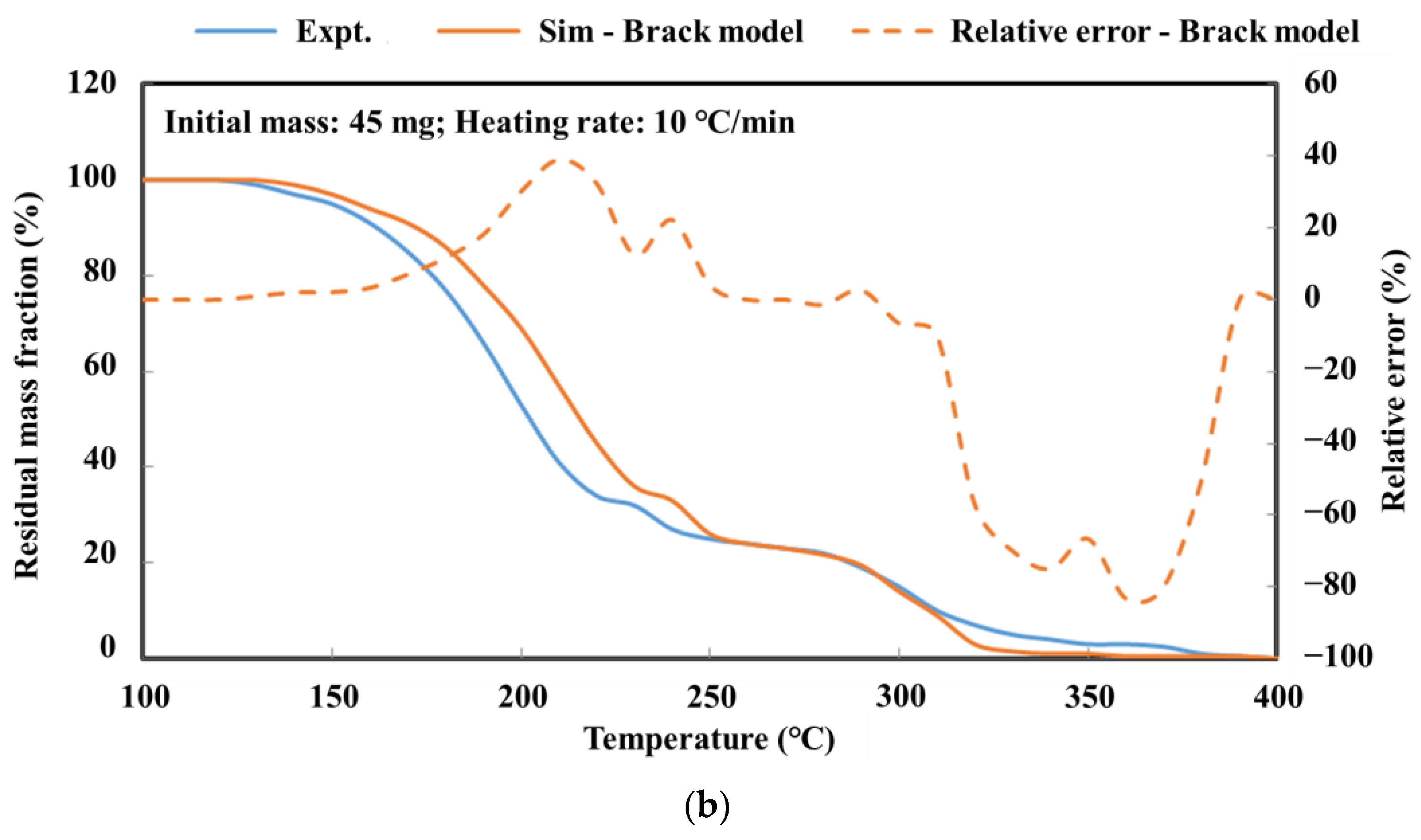
The detailed kinetic model of the deposit reaction is required to quantitatively describe the production of the deposit. Ebrahimian [17] has established the reaction kinetic model of the urea pyrolysis process. It considered four kinds of components of deposit, including urea, biuret, CYA and ammelide, which provided a guide for the quantitative study of deposit formation. Brack, et al. [18] have revised the reaction path based on the Ebrahimian mechanism model. They re-identified the reaction kinetic parameters, according to the results of thermogravimetric tests with different urea initial masses, temperature heating rates and reactor configurations. However, Figure 1 shows that the simulation values of urea pyrolysis, respectively, from the above reaction kinetic models established by Ebrahimian and Brack, are different from the experimental values.
In this study, thermal analysis technology was applied to the investigation of chemical reaction kinetics, and various classical thermal analysis kinetic methods were used to solve the activation energy of the decomposition reactions of urea and CYA. According to the Ebrahimian mechanism model, we re-identified the reaction kinetic parameters and established a deposit reaction kinetic model to describe the decomposition process of the key components in the deposit, attempting to provide a reference for the quantitative study of the deposit formation.

2. Results

2.1. Solving the Activation Energy of Urea Pyrolysis Reaction

2.1.1. The Flynn–Wall–Ozawa Method

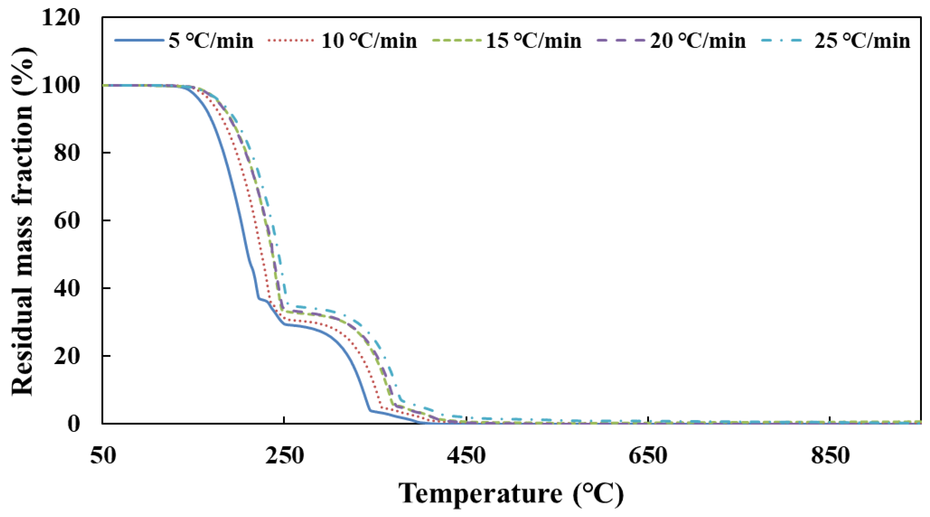
Figure 2 shows the TG curves of urea pyrolysis at different heating rates.
According to the TG curves of urea pyrolysis, the temperature data corresponding to each conversion rate are obtained at different heating rates. Table 1 shows the result of the activation energy of urea decomposition by substituting these data into Equation (24). E12 is the result from two sets of data with heating rates of 5 and 10 °C/min, E23, E34 and E45 to follow.
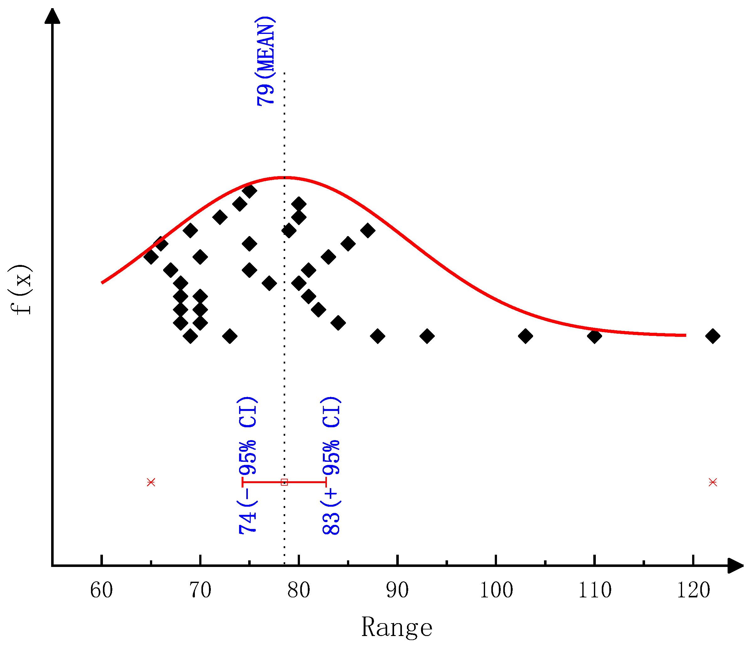
As the results show in Table 1, E34 has a large error in the process of calculating the activation energy of urea decomposition. The reason is that the two thermogravimetric curves of heating rates β3 and β4 almost coincide. The difference of temperature T corresponding to them is very small for the same conversion rate α, which brings a large error. Therefore, the set of data was discarded when calculating the total activation energy E. Finally, the activation energy of urea decomposition is 79 kJ/mol (95% confidence interval, CI: 74–83, as shown in Figure A1) calculated from the Ozawa method.

2.1.2. The Friedman-Reich-Levi Method

According to the TG curves of urea pyrolysis, dα/dT corresponding to each conversion rate is obtained at different heating rates. These data are substituted into Equation (28) to obtain the results of the activation energy of urea decomposition from the two-interval method (as shown in Table 2) and the one-interval method (as shown in Table 3).
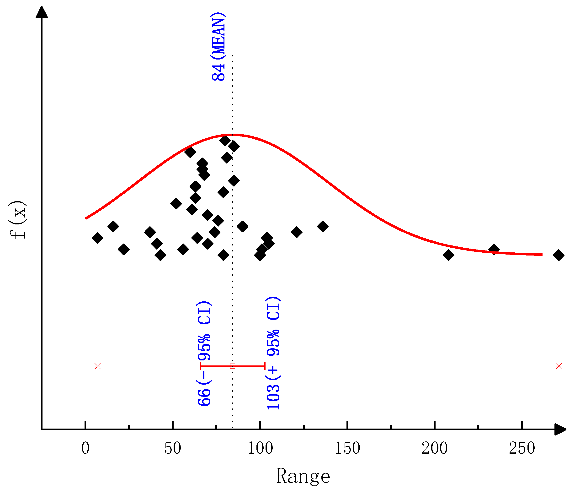
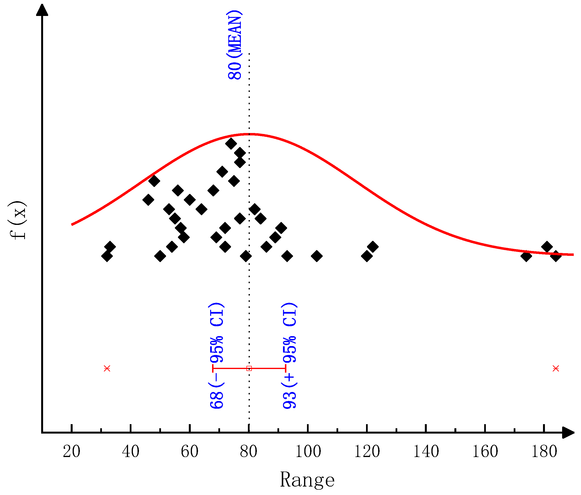
As the results show in Table 2 and Table 3, E34 has a large error in the process of calculating the activation energy of urea decomposition. The reason is that the two thermogravimetric curves of heating rates β3 and β4 almost coincide. The difference between temperature T and dα/dT corresponding to them is very small for the same conversion rate α, which brings a large error. Therefore, the set of data was discarded when calculating the total activation energy E. Finally, the activation energy of urea decomposition is 80 kJ/mol (95% confidence interval, CI: 68–93, as shown in Figure A2) calculated from the Friedman two-interval method and 84 kJ/mol (95% confidence interval, CI: 66–103, as shown in Figure A3) calculating from the Friedman one-interval method.

2.1.3. The Kissinger–Akahira–Sunose Method

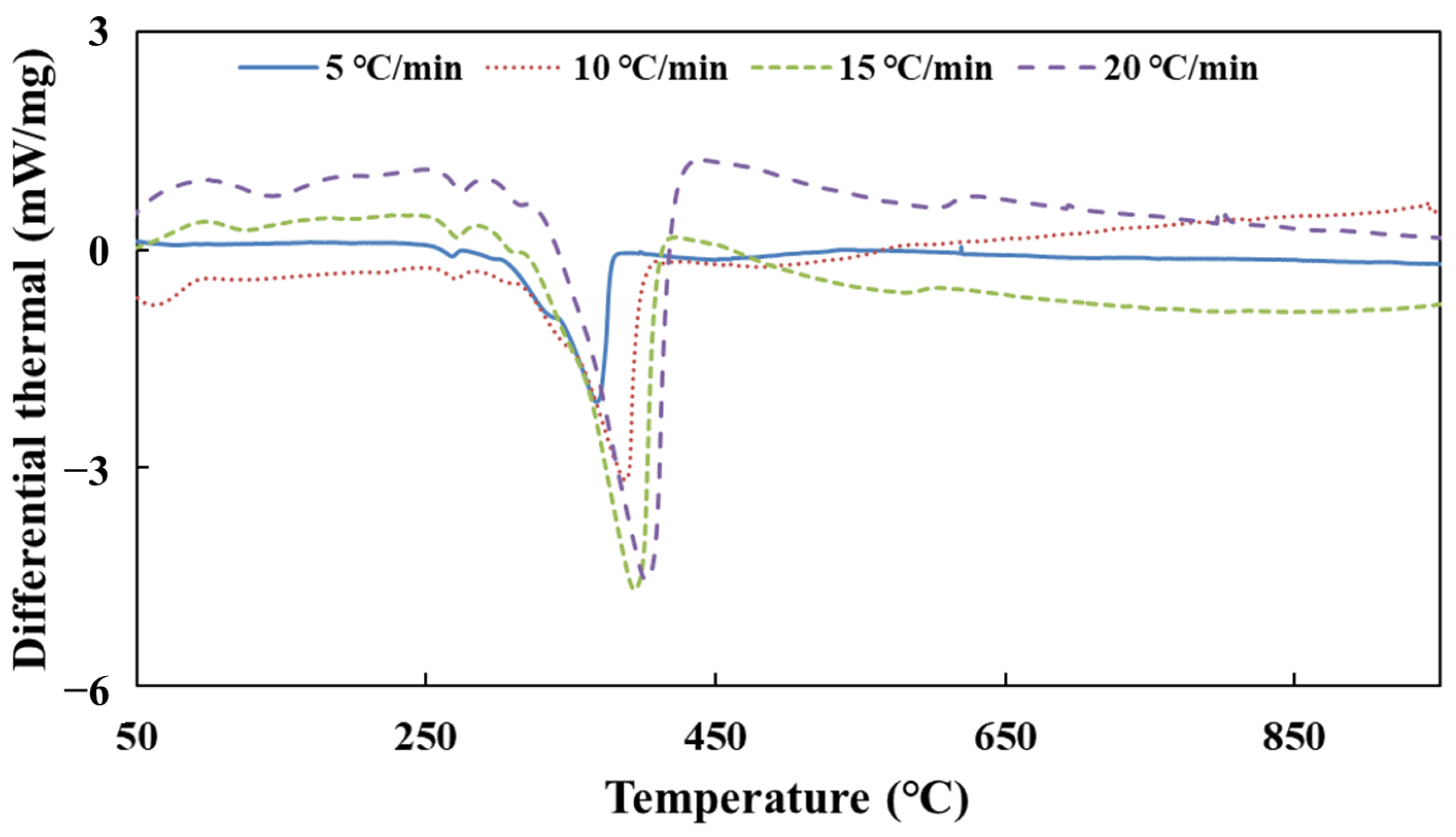
Figure 3 shows the DSC curves of urea pyrolysis at different heating rates.
According to the DSC curves of urea pyrolysis, the peak temperature date Tp is obtained at different heating rates. Table 4 shows the result of the activation energy of urea decomposition by substituting these data into Equation (32).
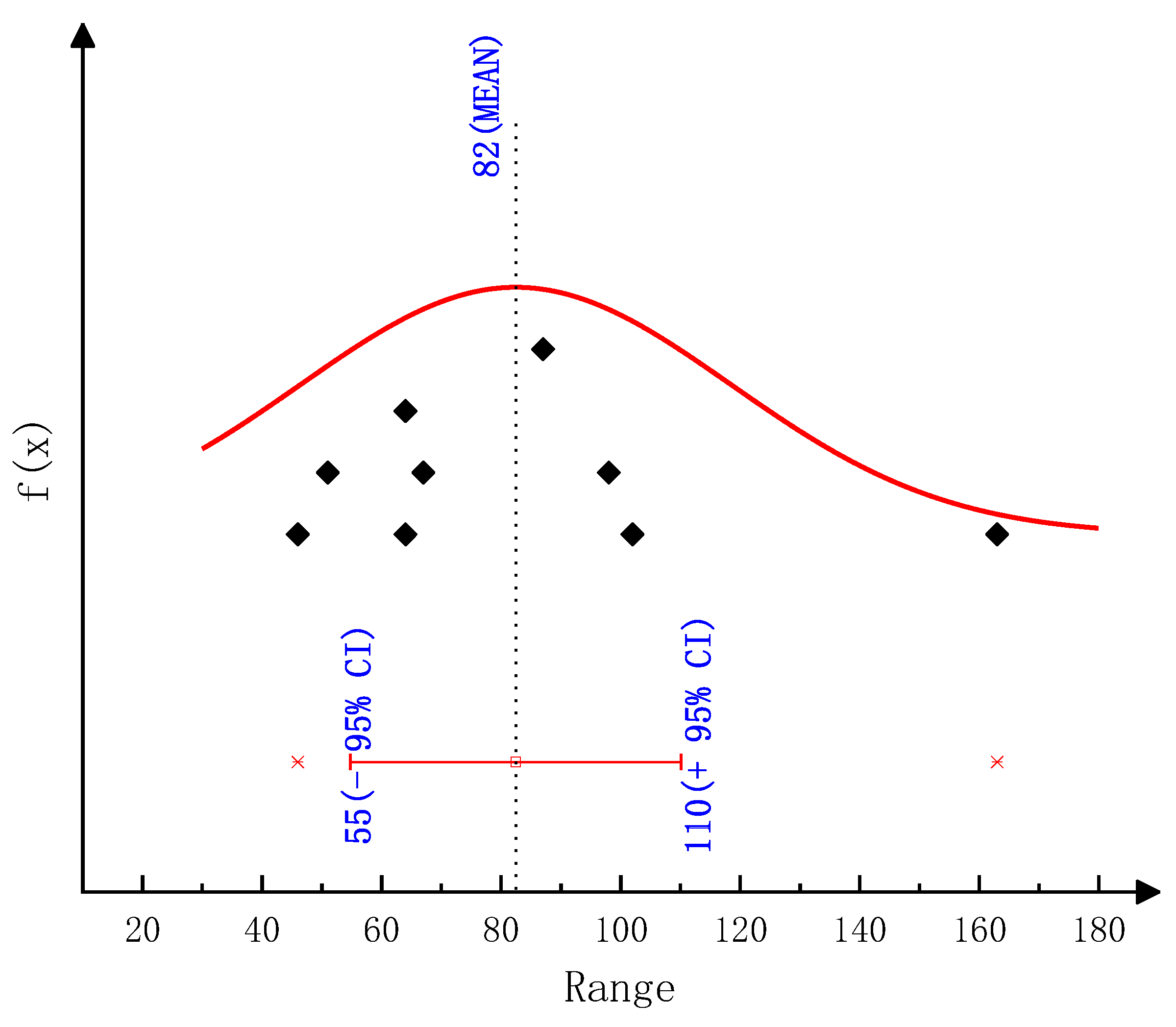
As the results show in Table 1, E34 has a large error in the process of calculating the activation energy of urea decomposition. The reason is that the difference between the peak temperatures Tp on the two DSC curves of heating rates β3 and β4 is very small, which brings a large error. Therefore, the set of data was discarded when calculating the total activation energy E. Finally, the activation energy of urea decomposition is 82 kJ/mol (95% confidence interval, CI: 55–110, as shown in Figure A4) calculated from the Kissinger method.

2.2. Solving the Activation Energy of Cyanuric Acid (CYA) Pyrolysis Reaction

2.2.1. The Flynn–Wall–Ozawa Method

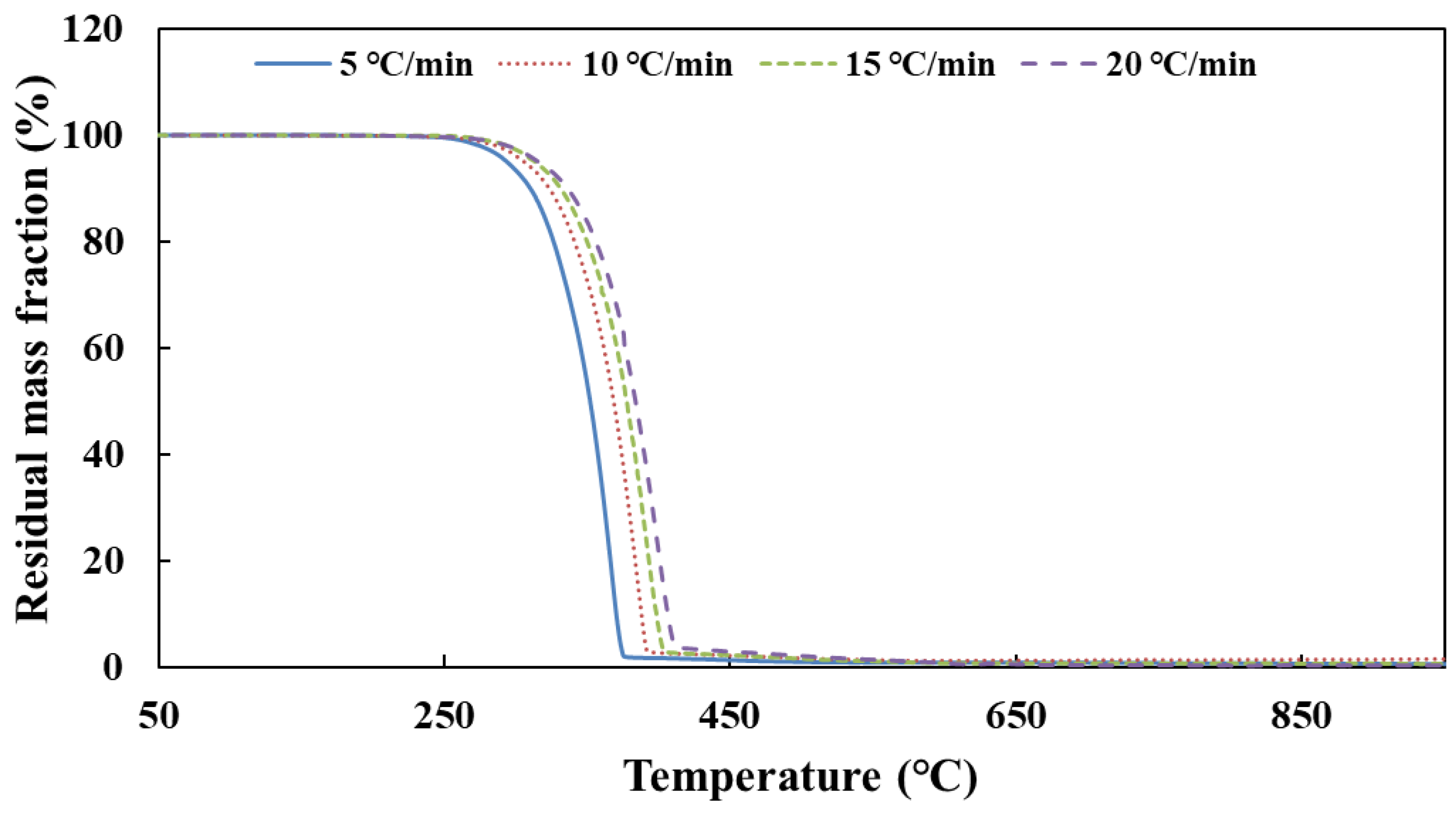
Figure 4 shows the TG curves of CYA pyrolysis at different heating rates.
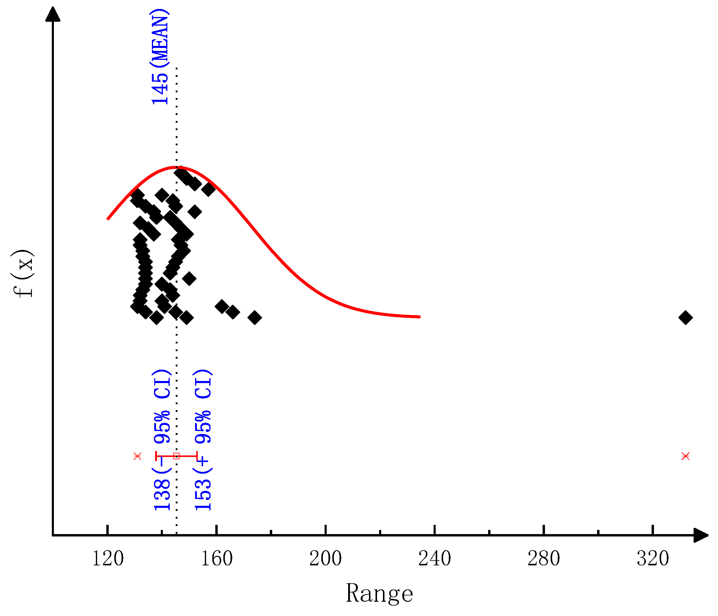
According to the TG curves of CYA pyrolysis, the temperature data corresponding to each conversion rate are obtained at different heating rates. Table 5 shows the result of the activation energy of CYA decomposition by substituting these data into Equation (24). Finally, the activation energy of CYA decomposition is 145 kJ/mol (95% confidence interval, CI: 138–153, as shown in Figure A5) calculated from the Ozawa method.

2.2.2. The Friedman–Reich–Levi Method

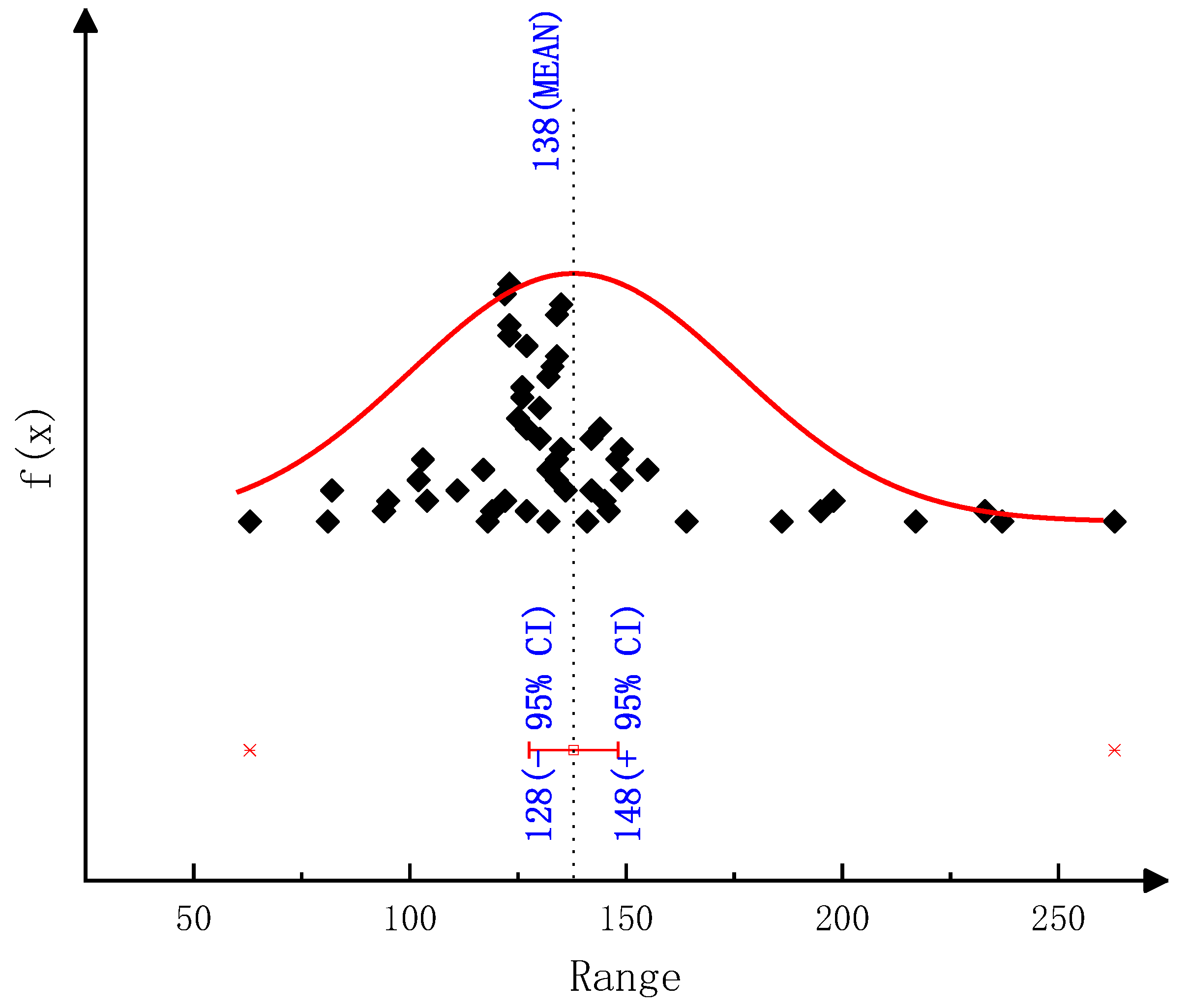
According to the TG curves of CYA pyrolysis, dα/dT corresponding to each conversion rate is obtained at different heating rates. These data are substituted into Equation (28) to obtain the results of the activation energy of CYA decomposition from the two-interval method (as shown in Table 6) and the one-interval method (as shown in Table 7). Finally, the activation energy of CYA decomposition is 138 kJ/mol (95% confidence interval, CI: 128–148, as shown in Figure A6) calculated from the Friedman two-interval method and 153 kJ/mol (95% confidence interval, CI: 124–182, as shown in Figure A7) calculated from the Friedman one-interval method.

2.2.3. The Kissinger–Akahira–Sunose Method

Figure 5 shows the DSC curves of CYA pyrolysis at different heating rates.
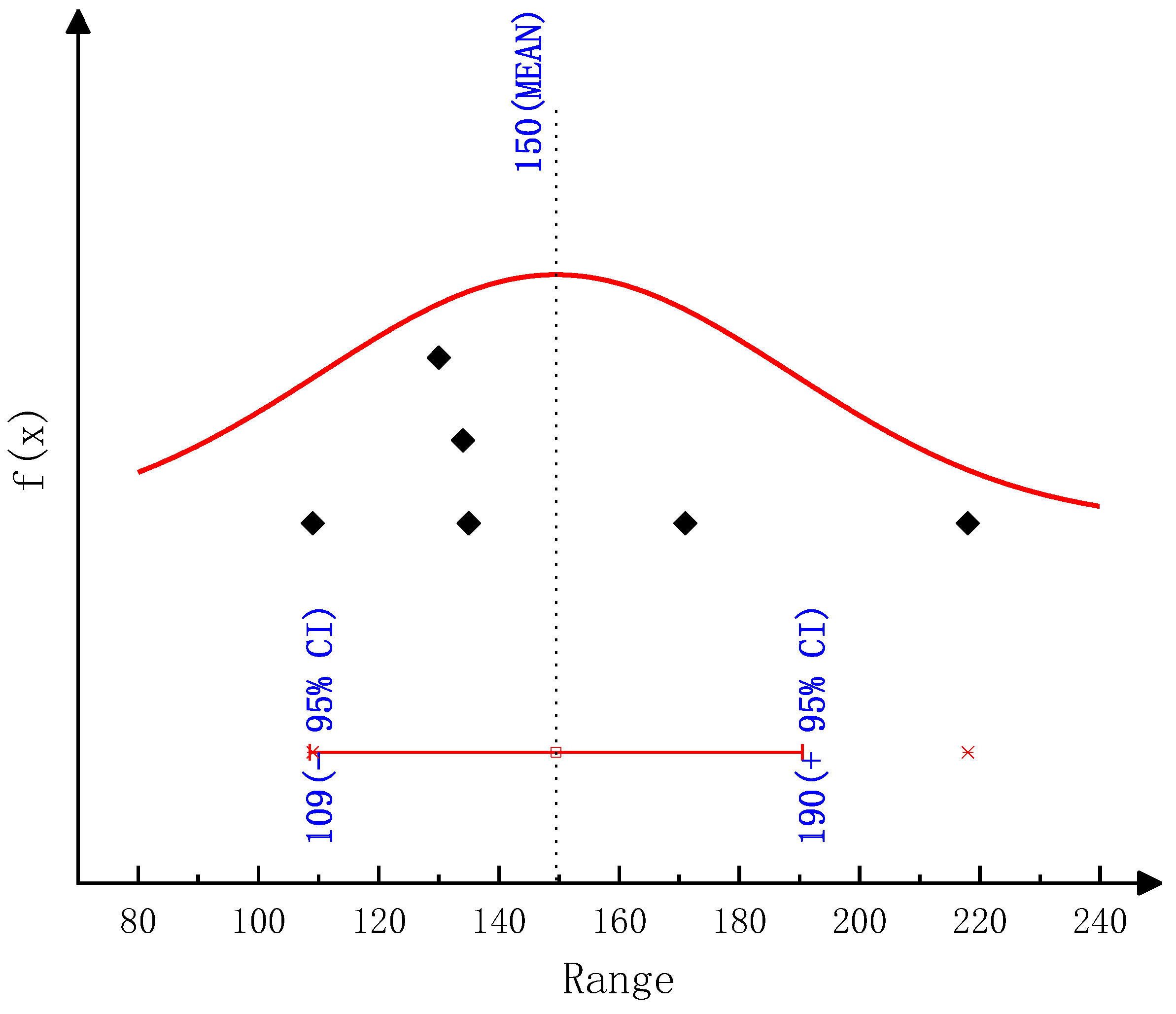
According to the DSC curves of CYA pyrolysis, the peak temperature data Tp is obtained at different heating rates. Table 8 shows the result of the activation energy of CYA decomposition by substituting these data into Equation (32). Finally, the activation energy of CYA decomposition is 150 kJ/mol (95% confidence interval, CI: 109–190, as shown in Figure A8) calculated from the Kissinger method.

2.3. Kinetic Modeling of Deposit Reaction

2.3.1. Reaction Path

Urea, biuret, CYA and ammelide are the four components of deposits. Equations (1)–(12) show the reaction paths of urea pyrolysis given by Ebrahimian.
R1            Urea → NH4+ + NCO
R2               NH4+ → NH3 + H+
R3             NCO + H+ → HNCO
R4           Urea + NCO + H+ → Biuret
R5           Biuret → Urea + NCO + H+
R6        Biuret + NCO + H+ → CYA + NH3
R7              CYA → 3NCO + 3H+
R8     CYA + NCO + H+ → Ammelide + CO2
R9    Ammelide → 2NCO + 2H+ + HCN + NH
R10             Urea (aq) → NH4+ + NCO
R11      NCO + H+ + H2O (aq) → NH3 + CO2
R12         Urea (aq) + NCO + H+ → Biuret
However, the above mechanism model does not distinguish the different shapes of urea from the perspective of deposit formation in the diesel SCR system. Therefore, the additional reaction paths as shown in Equations (13) and (14) are proposed for the transformation of different urea forms based on the Ebrahimian mechanism model. Moreover, the mechanism model of deposit reaction is established according to Equations (1)–(14).
R13            Urea (aq) → Urea [Dying]
R14      Urea (aq) → Urea [Crystallization]

2.3.2. Reaction Rate Equation

The generation rate of the component k can be expressed as follows [19] for the reaction R1–R12.
r k reaction = i = 1 N r e a c t i o n s ν k i A i exp ( E a , i R T ) j = 1 N s p e c i e s C s j ν j i
where: νki is the stoichiometric coefficient of the component k in the i-step reaction; A i is the reaction pre-exponential factor; Ea,i is the reaction activation energy; Csj is the surface concentration of the component j.
A i can be calculated by the following equation:
A i = A i Γ n i 1
where: Γ is the active site density; ni is the number of activity levels.
The active surface can be calculated by the following equation, assuming the effective area of the model does not change during the whole calculation process.
S = k = 1 N s p e c i e s m k initial σ k W k Γ
where: σk is the active site occupied by component k; Wk is the molecular mass of the component k.
Csj can be calculated by the following equation:
C s j = m j S W j
The generation rate of component k can be expressed as follows for the reaction R13.
r k dying = K dying exp ( A dying f H 2 O f H 2 O max ) C s urea _ aq
where: Kdying and Adying are coefficients; fH2O is the component concentration of water in the aqueous urea solution; f H 2 O max takes the value of 0.876.
The generation rate of component k can be expressed as follows for the reaction R14.
r k cry = K cry exp [ A cry ( T C cry ) ] ( w urea w miller )
where: Kcry and Acry are coefficients; Ccry takes the value of 233.4 K.

2.3.3. The Model Parameters Identification and Validation

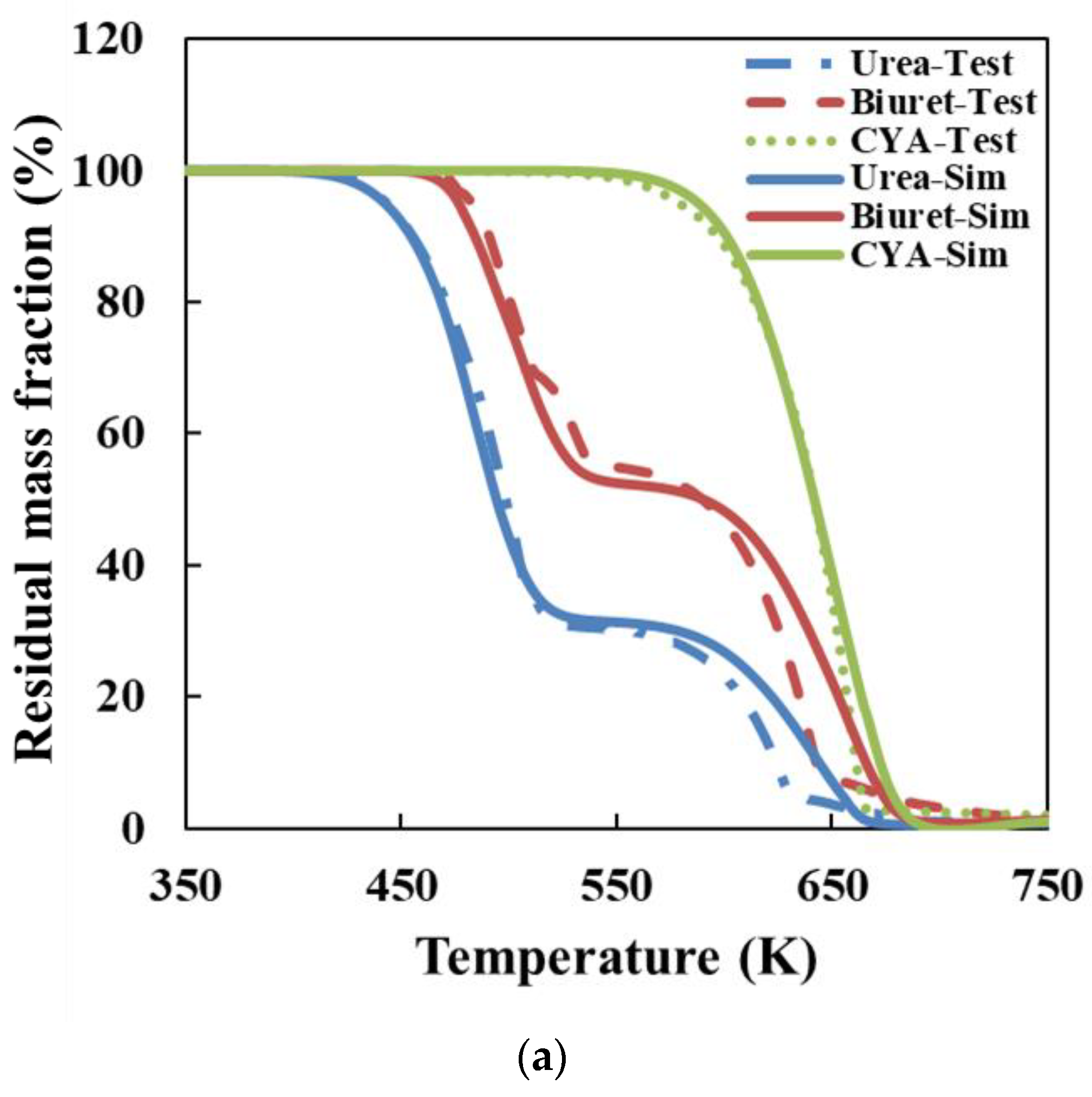
The kinetic parameters of the deposit reaction model were identified, according to the results of thermal analysis experiments for urea, biuret, and CYA. The initial values of the kinetic parameters for the reactions R1–R12 are referred to in the Ebrahimian mechanism model. The value range of activation energy is set to 78–85 kJ/mol for the urea decomposition reaction R1 and 137–153 kJ/mol for the CYA decomposition reaction R7, referring to the results in Section 3.1 and Section 3.2. Table 9 shows the identification results of reaction kinetic parameters. It can be observed that the activation energy of the urea decomposition reaction is 84 kJ/mol and CYA is 152 kJ/mol after identification. Both of the identified activation energies are closest to the results of the Friedman one-interval method.
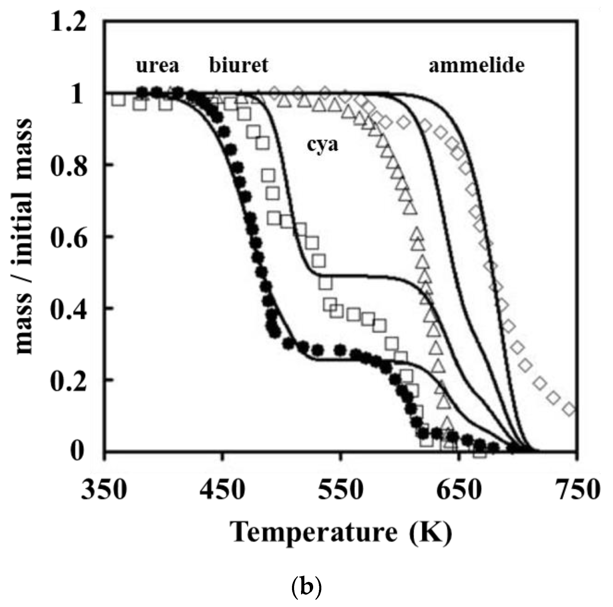
Figure 6a shows the simulation results of the deposit reaction kinetic model in this paper and the thermogravimetric experimental results. The model in this paper can describe the key components of deposit decomposition accurately. Ebrahimian also obtained the comparison of thermogravimetric test and simulation results for each component of the deposits, as shown in Figure 6b. In the Ebrahimian model, the simulation results have an appreciable error above 600 K, which is the initiation temperature of CYA decomposition. We have solved the chemical reaction activation energy of CYA decomposition through the thermogravimetric test. It is employed to constrain the value of parameter identification and enhance the simulation accuracy of the deposit reaction kinetic model over 600 K.

3. Materials and Methods

3.1. Test Equipment

The integrated thermal analyzer STA449F3 made by German NETZSCH company was employed to simultaneously measure the mass and energy difference curves of the sample with temperature or time, which is to say the TG and DSC curves.

3.2. Test Sample

The purity of urea used in the test was not less than 99%, which was provided by Tianjin Guangfu Technology Development Company Limited.

3.3. Test Conditions

Each test sample was pulverized into powder form in an agate mortar, and about 10 mg of the sample was placed in an alumina crucible (3 mm in diameter). The purge gas in the heating furnace was Ar with a flow rate of 40 mL/min. The samples were heated from room temperature to 1000 °C at the heating rate of 2, 5, 10, 15, 20, and 25 °C/min.

3.4. Kinetic Analysis Method of Thermal Analysis Curves

3.4.1. The Flynn–Wall–Ozawa Method

The Ozawa equation is as follows [20,21]:
ln β = ln A E R G ( α ) 5.3308 1.0516 E R T
where: β is the heating rate (generally constant); α is the conversion rate; A is the pre-exponential factor; E is the activation energy; R is the molar gas constant; T is the thermodynamic temperature.
The intersection points (α, T1, β1) and (α, T2, β2) with the same conversion rate α on the two TG curves of different heating rates β1 and β2 are substituted into Equation (21) to obtain:
ln β 1 = ln A E R G ( α ) 5.3308 1.0516 E R T 1
ln β 2 = ln A E R G ( α ) 5.3308 1.0516 E R T 2
Subtracting Equation (23) from Equation (22) to obtain:
ln β 1 β 2 = E R 1.0516 T 1 T 2 T 1 T 2
The values of α are usually 0.95, 0.90, 0.85, …, 0.15, 0.10. An α can solve a value of E, and the reasonable activation energy E can be eventually determined by analyzing all the solved E values logically.

3.4.2. The Friedman–Reich–Levi Method

The Friedman equation is as follows [22,23]:
ln ( β d α d T ) = ln [ A f ( α ) ] E R T
The intersection points (α, T1, (dα/dT)1, β1) and (α, T2, (dα/dT)2, β2) with the same conversion rate α on the two TG curves of different heating rates β1 and β2 are substituted into Equation (25) to obtain:
ln β 1 ( d α d T ) 1 = ln A f ( α ) E R T 1
ln β 2 ( d α d T ) 2 = ln A f ( α ) E R T 2
Subtracting Equation (27) from Equation (26) to obtain:
ln β 1 ( d α d T ) 1 β 2 ( d α d T ) 2 = E R ( T 1 T 2 T 1 T 2 )
The values of α are usually 0.95, 0.90, 0.85, …, 0.15, 0.10. An α can solve a value of E, and the reasonable activation energy E can be finally determined by analyzing all the solved E values logically.
There are two ways to calculate ΔαT, assuming dα/dT ≈ ΔαT and taking the three adjacent points (α1, T1), (α2, T2) and (α3, T3) when processing the experimental data. For point (α2, T2), there are:
(i)
Two-interval calculation method: dα/dT ≈ ΔαT = (α3α1)/(T3T1);
(ii)
One-interval calculation method: The points (α1, T1) and (α3, T3) are averaged to obtain the new point (α′, T′), then dα/dT ≈ ΔαT = (α2α′)/(T2T′).

3.4.3. The Kissinger–Akahira–Sunose Method

The Kissinger equation is as follows [24]:
ln ( β i T p i 2 ) = ln A R E E R 1 T p i ( i = 1 , 2 , )
The points (Tp1, β1) and (Tp2, β2) at the peak temperature Tp on the two DSC curves of different heating rates β1 and β2 are substituted into Equation (29) to obtain:
ln ( β 1 T p 1 2 ) = ln A R E E R 1 T p 1
ln ( β 2 T p 2 2 ) = ln A R E E R 1 T p 2
Subtracting Equation (31) from Equation (30) to obtain:
ln ( β 1 T p 2 2 β 2 T p 1 2 ) = E R ( T p 1 T p 2 T p 1 T p 2 )
According to Equation (32), any two DSC curves can solve a value of E. All the solved E values are analyzed logically, and the reasonable activation energy E can be finally determined.

4. Conclusions

According to the thermogravimetric test results, we employed various classical thermal analysis kinetic methods to solve the activation energies of the thermal decomposition reactions of urea and CYA. The activation energy of the urea decomposition reaction: the result is 78.44 kJ/mol by the Ozawa method, 80.12 kJ/mol by the Friedman two-interval method, 84.34 kJ/mol by the Friedman one-interval method and 82.64 kJ/mol by the Kissinger method. The activation energy of CYA decomposition reaction: the result is 145.38 kJ/mol by the Ozawa method, 137.83 kJ/mol by the Friedman two-interval method, 152.57 kJ/mol by the Friedman one-interval method and 149.34 kJ/mol by the Kissinger method. After identifying the reaction kinetic parameters in the model of this paper, the activation energies of the decomposition reactions of urea and CYA are 84 kJ/mol and 152 kJ/mol, respectively. The established deposit reaction kinetic model can accurately describe the decomposition process of each key component of deposits. What is more, the simulation accuracy is significantly improved above 600 K, which can provide a reference for the quantitative study of deposit formation.
Author Contributions

Conceptualization, N.Z.; investigation, F.Q.; writing—original draft preparation, Y.H.; writing—review and editing, X.X. All authors have read and agreed to the published version of the manuscript.

Funding

This research was funded by Natural Science Foundation of Hubei Province, grant number 2022CFB730.

Institutional Review Board Statement

Not applicable.

Informed Consent Statement

Not applicable.

Data Availability Statement

No new data were created or analyzed in this study. Data sharing is not applicable to this article.

Acknowledgments

The authors appreciate the support of the School of Automotive and Transportation Engineering (Wuhan University of Science and Technology) and the Wuhan University of Technology.

Conflicts of Interest

The authors declare no conflict of interest.

Sample Availability

Samples of the compounds are available from the authors.

Appendix A

Figure A1. 95% confidence interval for the activation energy EO of urea pyrolysis reaction.
Molecules 28 02340 g0a1
Figure A2. 95% confidence interval for the activation energy EF,2 of urea pyrolysis reaction.
Molecules 28 02340 g0a2
Figure A3. 95% confidence interval for the activation energy EF,1 of urea pyrolysis reaction.
Molecules 28 02340 g0a3
Figure A4. 95% confidence interval for the activation energy EK of urea pyrolysis reaction.
Molecules 28 02340 g0a4
Figure A5. 95% confidence interval for the activation energy EO of CYA pyrolysis reaction.
Molecules 28 02340 g0a5
Figure A6. 95% confidence interval for the activation energy EF,2 of CYA pyrolysis reaction.
Molecules 28 02340 g0a6
Figure A7. 95% confidence interval for the activation energy EF,1 of CYA pyrolysis reaction.
Molecules 28 02340 g0a7
Figure A8. 95% confidence interval for the activation energy EK of CYA pyrolysis reaction.
Molecules 28 02340 g0a8

References

  1. Song, X.; Johnson, J.H.; Naber, J.D. A review of the literature of selective catalytic reduction catalysts integrated into diesel particulate filters. Int. J. Engine Res. 2015, 16, 738–749. [Google Scholar] [CrossRef]
  2. Johnson, T.V. Diesel Emissions in Review. SAE Int. J. Engines 2011, 4, 143–157. [Google Scholar] [CrossRef]
  3. Lv, L.; Wang, L. Model-based optimization of parameters for a diesel engine SCR system. Int. J. Automot. Technol. 2013, 14, 13–18. [Google Scholar]
  4. Zhu, N. Investigation on the Formation Mechanism of Deposit in the Exhaust Pipe of SCR System for Diesel Engine. Ph.D. Thesis, Wuhan University of Technology, Wuhan, China, 2017. [Google Scholar]
  5. Xu, L.; Watkins, W.; Snow, R.; Graham, G.; McCabe, R.; Lambert, C.; Carter, R.O. Laboratory and Engine Study of Urea-Related Deposits in Diesel Urea-SCR After-Treatment Systems. SAE Tech. Pap. 2007, 116, 202–209. [Google Scholar] [CrossRef]
  6. Way, P.; Viswanathan, K.; Preethi, P.; Gilb, A.; Zambon, N.; Blaisdell, J. SCR Performance Optimization through Advancements in Aftertreatment Packaging. SAE Tech. Pap. 2009. [Google Scholar] [CrossRef]
  7. Feng, X.; Ge, Y.; Ma, C.; Han, X.C.; Tan, J.W.; Li, J.Q. Study on deposit formation in urea-SCR system of diesel engine. Neiranji Gongcheng/Chin. Intern. Combust. Engine Eng. 2014, 35, 1–6. [Google Scholar]
  8. Zhu, N.; Lv, L.; Ye, C. Component analysis of deposits in selective catalytic reduction system for automotive diesel engine. In MATEC Web of Conferences; EDP Sciences: Les Ulis, France, 2016; Volume 51. [Google Scholar]
  9. Zhu, N.; Lv, L.; Yang, D. Study on factors influencing the deposit formation in the exhaust pipes of SCR diesel engine. Neiranji Gongcheng/Chin. Intern. Combust. Engine Eng. 2015, 36, 8–13. [Google Scholar]
  10. Dong, H.; Shuai, S.; Wang, J. Effect of Urea Thermal Decomposition on Diesel NOx-SCR Aftertreatment Systems. SAE Tech. Pap. 2008. [Google Scholar] [CrossRef]
  11. Schaber, P.M.; Colson, J.; Higgins, S.; Thielen, D.; Anspach, B.; Brauer, J. Thermal decomposition (pyrolysis) of urea in an open reaction vessel. Thermochim. Acta 2004, 424, 131–142. [Google Scholar] [CrossRef]
  12. Zhao, Y. Experimental Study of Urea Solution Spray and Decomposition and Ammonia Storage in Selective Catalytic Reduction System for Diesel Engines. Ph.D. Thesis, Tsinghua University, Beijing, China, 2012. [Google Scholar]
  13. Thagard, S.M.; Mihalcioiu, A.; Takashima, K.; Mizuno, A. Analysis of the by-products in the ammonia production from urea by dielectric barrier discharge. IEEE Trans. Plasma Sci. 2009, 37, 444–448. [Google Scholar] [CrossRef]
  14. Stradella, L.; Argentero, M. A study of the thermal decomposition of urea, of related compounds and thiourea using DSC and TG-EGA. Acta 1993, 219, 315–323. [Google Scholar] [CrossRef]
  15. Carp, O. Considerations on the thermal decomposition of urea. Rev. Roum. Chim. 2001, 46, 735–740. [Google Scholar]
  16. Lundström, A.; Andersson, B.; Olsson, L. Urea thermolysis studied under flow reactor conditions using DSC and FT-IR. Chem. Eng. J. 2009, 150, 544–550. [Google Scholar] [CrossRef]
  17. Ebrahimian, V. Development of Multi-Component Evaporation Models and 3D Modeling of NOx-SCR Reduction System. Ph.D. Thesis, University of Otago, Dunedin, New Zealand, 2011. [Google Scholar]
  18. Brack, W.; Heine, B.; Birkhold, F.; Kruse, M.; Schoch, G.; Tischer, S.; Deutschmann, O. Kinetic modeling of urea decomposition based on systematic thermogravimetric analyses of urea and its most important by-products. Chem. Eng. Sci. 2014, 106, 1–8. [Google Scholar] [CrossRef]
  19. Ebrahimian, V.; Nicolle, A.; Habchi, C. Detailed Modeling of the Evaporation and Thermal Decomposition of Urea-Water Solution in SCR Systems. Aiche J. 2012, 58, 1998–2009. [Google Scholar] [CrossRef] [Green Version]
  20. Ozawa, T. A New Method of Analyzing Thermogravimetric Data. Bull. Chem. Soc. Jpn. 1965, 38, 1881–1886. [Google Scholar] [CrossRef] [Green Version]
  21. Flynn, J.H.; Wall, L.A. A quick, direct method for the determination of activation energy from thermogravimetric data. J. Polym. Sci. Part B Polym. Lett. 1966, 4, 323–328. [Google Scholar] [CrossRef]
  22. Friedman, H.L. Kinetics and Gaseous Products of Thermal Decomposition of Polymers. J. Macromol. Sci. Part A Chem. 1967, 41, 57–79. [Google Scholar] [CrossRef]
  23. Reich, L.; Levi, W. Polymer degradation by differential thermal analysis techniques. J. Polym. Sci. Macromol. Rev. 1968, 3, 173. [Google Scholar] [CrossRef]
  24. Kissinger, H.E. Reaction Kinetics in Differential Thermal Analysis. Anal. Chem. 1957, 29, 1702–1706. [Google Scholar] [CrossRef]
Figure 1. Experimental and simulation results comparison of urea pyrolysis (a) Comparison result of Ebrahimian model (b) Comparison result of Brack model.
Molecules 28 02340 g001aMolecules 28 02340 g001b
Figure 2. The TG curves of urea pyrolysis at different heating rates.
Molecules 28 02340 g002
Figure 3. The DSC curves of urea pyrolysis at different heating rates.
Molecules 28 02340 g003
Figure 4. The TG curves of CYA pyrolysis at different heating rates.
Molecules 28 02340 g004
Figure 5. The DSC curves of CYA pyrolysis at different heating rates.
Molecules 28 02340 g005
Figure 6. Comparison of the simulation and experiment results of the deposit reaction kinetic model (a) Model in this paper (b) Ebrahimian model. (Solid line-simulation, symbol-test).
Molecules 28 02340 g006aMolecules 28 02340 g006b
Table 1. The activation energy EO of urea decomposition (Unit: kJ/mol).
1 − αE12E23E34E45 E ¯ EO
0.959380−5971229879
0.908873−6327579
0.858470−6256774
0.808269−7646572
0.758168−15286672
0.708068−73257073
0.65817014846973
0.6083706577576
0.5585685117977
0.50876852397276
0.45103775147485
0.40110804207588
Table 2. The activation energy EF,2 of urea decomposition from two-interval method (Unit: kJ/mol).
1 − αE12E23E34E45 E ¯ EF,2
0.959350−539536580
0.907964−6963258
0.857254−6644657
0.806960−7365662
0.757258−14167769
0.707768−63167473
0.6586759123365
0.608957482174107
0.559155388181109
0.501037171894874
0.4518412226084130
0.40120774948293
Table 3. The activation energy EF,1 of urea decomposition from one-interval method (Unit: kJ/mol).
1 − αE12E23E34E45 E ¯ EF,1
0.957970−432677284
0.905661−6962246
0.857052−8584154
0.806463−1241745
0.757479−6148178
0.7010063−79766074
0.6590855598587
0.6076684503760
0.55101434011653
0.5010567632312198
0.45208271−1289136205
0.40104234−57480139
Table 4. The activation energy EK of urea decomposition (Unit: kJ/mol).
ParameterValue
E1246
E1351
E1464
E1567
E2364
E24102
E2598
E34431
E35163
E4587
EK82
Table 5. The activation energy EO of CYA decomposition (Unit: kJ/mol).
1 − αE12E23E34 E ¯ EO
0.95149140332207145
0.90145144174154
0.85141143152145
0.80138140145141
0.75134137144138
0.70131150132138
0.65132143140138
0.60132144166147
0.55133145162147
0.50134146157146
0.45134148152145
0.40134147149143
0.35134146147142
0.30134149138140
0.25133147137139
0.20133145134137
0.15132143131135
0.10132135131133
Table 6. The activation energy EF,2 of CYA decomposition from two-interval method (Unit: kJ/mol).
1 − αE12E23E34 E ¯ EF,2
0.95132146195158138
0.90141145123136
0.85127133117126
0.80118134134129
0.75119127144130
0.70122186263190
0.65136142135138
0.60134149237173
0.55132155122136
0.50134148233172
0.45135104164134
0.40130149217165
0.3512781198135
0.3012514294120
0.25130111123121
0.2012612395115
0.1512610282103
0.101326310399
Table 7. The activation energy EF,1 of CYA decomposition from one-interval method (Unit: kJ/mol).
1 − αE12E23E34 E ¯ EF,1
0.95136112401216153
0.90141119146135
0.85117134132128
0.80115133121123
0.75110117153127
0.70102220124149
0.65127144123131
0.60130148763347
0.55103180110131
0.50126139119128
0.45131116195147
0.4014014184122
0.3513044280151
0.3012121886142
0.2515488150131
0.20123101136120
0.1511411576102
0.10116121415217
Table 8. The activation energy EK of CYA decomposition (Unit: kJ/mol).
ParameterValue
E12109
E13135
E14134
E23218
E24171
E34130
EK150
Table 9. The identification results of reaction kinetic parameters.
ReactionInitialAfter Identification
E (kJ/mol)A (s−1)E (kJ/mol)A (s−1)
R1848.50 × 106848.71 × 106
R2401.50 × 102401.91 × 102
R3106.57 × 102106.30 × 102
R41157.87 × 10141008.01 × 1014
R52501.50 × 10242432.28 × 1024
R61502.81 × 10181442.83 × 1018
R72601.50 × 10191522.50 × 1010
R8353.48 × 105363.35 × 105
R92206.00 × 10142125.67 × 1014
R10841.20 × 108841.20 × 108
R11595.62 × 109595.62 × 109
R121153.93 × 10141153.93 × 1014
R13Dying_KDying_ADying_KDying_A
11001100
R14Cry_KCry_ACry_KCry_A
1−0.000 51−0.000 5
Disclaimer/Publisher’s Note: The statements, opinions and data contained in all publications are solely those of the individual author(s) and contributor(s) and not of MDPI and/or the editor(s). MDPI and/or the editor(s) disclaim responsibility for any injury to people or property resulting from any ideas, methods, instructions or products referred to in the content.