Abstract
Exploring anode materials with an excellent electrochemical performance is of great significance for supercapacitor applications. In this work, a N-doped-carbon-nanofiber (NCNF)-supported Fe3C/Fe2O3 nanoparticle (NCFCO) composite was synthesized via the facile carbonizing and subsequent annealing of electrospinning nanofibers containing an Fe source. In the hybrid structure, the porous carbon nanofibers used as a substrate could provide fast electron and ion transport for the Faradic reactions of Fe3C/Fe2O3 during charge–discharge cycling. The as-obtained NCFCO yields a high specific capacitance of 590.1 F g−1 at 2 A g−1, superior to that of NCNF-supported Fe3C nanoparticles (NCFC, 261.7 F g−1), and NCNFs/Fe2O3 (NCFO, 398.3 F g−1). The asymmetric supercapacitor, which was assembled using the NCFCO anode and activated carbon cathode, delivered a large energy density of 14.2 Wh kg−1 at 800 W kg−1. Additionally, it demonstrated an impressive capacitance retention of 96.7%, even after 10,000 cycles. The superior electrochemical performance can be ascribed to the synergistic contributions of NCNF and Fe3C/Fe2O3.
1. Introduction
The development and application of renewable energy resources such as solar, wind, and water energy have created an urgent need for high-efficiency electric power sources in recent decades [1,2]. Among them, supercapacitors (SCs) have received tremendous attention, owing to their unique features such as a low maintenance cost, environmental friendliness, and a high charge efficiency, as well as a long cyclic life [3,4]. Nevertheless, SCs always suffering from a low energy density, which leads to poor endurance, and seriously hampers large-scale practical applications. According to the formula of energy density (E = 0.5CV2) of SCs [5,6], the primary strategies for obtaining high-performance devices are to utilize high-specific-capacitance (C) active materials that store charges relying on the Faradic reactions and/or electrical double layer capacitance (EDLC), and to design an asymmetric structure to extend the operation voltage window (V) [7,8].
To date, massive efforts have focused on exploring electrode materials with a high capacitive performance and long-term cycling stability [9,10]. In prior works, diverse active materials have been applied to construct electrodes for high-performance SC applications, such as transition metal oxides/carbides/sulfides/phosphides, carbonaceous materials, conducting polymers [11,12], etc. Among them, the Fe-based oxides/carbides (e.g., Fe2O3, Fe3O4, Fe3C, etc.) exhibit an outstanding electrochemical performance, with aspects such as a high theoretical specific capacitance, a large voltage window, and multivalent states [13,14]. Moreover, the multiple crystalline forms, low toxicity, rich resources, and low cost impel them to be extensively used as an anode for SCs [15]. Nevertheless, they also suffer from poor conductivity and a disappointing structural stability during the electrochemical reaction process, leading to a bad rate capacity and poor cyclic life [16,17,18]. To address these issues, carbonaceous materials (e.g., carbon cloth, carbon nanoarray, graphene, etc.) are widely used in combining Fe-based oxides/carbides, to design a high-performance electrode material relying on their excellent conductivity, outstanding stability, and environmental friendliness [19,20]. For example, Yuan et al. prepared ultrasmall Fe2O3-embedded carbon nanotubes through facile dipping and combustion processes, using carbon cloth as the substrate [21]. Benefiting from its unique architecture, the optimized sample displayed outstanding hydrophilia and delivered the high specific capacitance of 483.4 mF cm−2. The flexible device constructed using this nanostructure composite exhibited the high working voltage of 2.0 V, and delivered the large energy density of 0.11 mWh cm−2. To further enhance the electrochemical performance of an Fe-based oxide/porous carbon composite, heteroatom-doped porous carbon nanomaterials are used to anchored Fe-based oxides/carbides. These heteroatoms (such as N, S, P, etc.) in carbon lattice are facilitated, to enhance electrical conductivity, and can further contribute a remarkable pseudocapacitance to the as-obtained porous carbon nanomaterials, which has a cooperative effect on the preparative high-performance electrode materials [22,23,24]. For instance, Xia et al. fabricated N-doped-carbon-nanoarray-supported Fe2O3 nanoneedles on carbon cloth, through immersion and subsequent hydrothermal steps [25]. This hybrid structure could enhance the conductivity of Fe2O3, and provide sufficient diffusion channels for Faradic reactions and ion transfer. A symmetric SC based on the as-obtained composite showed the high energy density of 14.1 Wh kg−1.
Although locating Fe-based oxides/carbides on carbonaceous substrates could effectively lead to the construction of high-performance electrode materials for SCs, the complex preparation procedures and high cost mean that it is still difficult for them to meet the demands of practical application. Additionally, the carbonaceous substrates, such as carbon cloth, with a poor capacitance contribution and large mass/volume proportion would lead to a low gravimetric/volumetric specific capacitance in the as-assembled SC devices [26], which is not conducive to the development of lightweight devices. Compared to other carbonaceous materials, electrospinning carbon nanofibers (ECNFs) with advantageous architecture, such as a large specific surface area (SSA), and functional integration characteristics are recognized as an ideal substrate and electrode material for SCs, and have been the subject of tremendous research in recent years [27,28,29]. For example, Yang et al. located Fe3+ onto electrospinning nanofiber precursors via ion exchanging [14]. After carbonizing at high temperatures, the FexCy/Fe nanoparticles were inserted into N-doped ECNFs. The as-obtained flexible electrode displayed superior electrochemical performances (340 F g−1 at 1 A g−1). Accordingly, anchoring Fe-based oxides/carbides into N-doped ECNFs is a valid way to construct excellent electrode materials for SCs. Nevertheless, the preparation methods (such as ion exchange, hydrothermal synthesis, and electrodeposition) of Fe-based oxides/carbides/N-doped ECNFs generally involve tedious procedures that cannot meet the demands of large-scale application. More importantly, the hybrid architecture composites fabricated through these methods show a loose contact between Fe-based oxides/carbides and ECNFs, which is adverse for electron transfer and for buffering the volume changes during the charge–discharge process, leading to a disappointing rate capability and significant deterioration of the cycling performance. Hence, researching facile synthesis methods to design Fe-based oxide/carbide/N-doped ECNF composites with an excellent electrochemical performance should be further attempted.
Herein, an Fe3C/Fe2O3-anchored N-doped ECNF (NCFCO) hybrid structure nanocomposite was prepared by facile-carbonizing and oxidizing the electrospun nanofiber precursor containing polyacrylonitrile and iron acetylacetonate, and its electrochemical performance as an electrode for SCs was assessed using different electrochemical measurements. Benefiting from the synergetic effect of the Fe3C/Fe2O3 and N-doped ECNFs, the as-prepared NCFCO exhibited a remarkably reinforced specific capacitance of 590.1 F g−1 at 2 A g−1, much higher than those of Fe3C-anchored N-doped ECNFs (NCFC, 261.7 F g−1) and Fe2O3 nanoparticle/N-doped ECNF composite (NCFO, 398.3 F g−1). Importantly, the asymmetric SC based on our NCFCO anode and commercial activated carbon (AC) cathode delivered the high energy density of 14.2 Wh kg−1 at 800 W kg−1, and the surface morphology of the NCFCO electrode showed almost no change after long-cycling, demonstrating that integrating Fe-based oxides/carbides into N-doped ECNFs by electrospinning, to construct high-performance electrode material for SC applications, is an extremely effective method.
2. Results and Discussion
The preparation procedures of the NCFCO are shown in Figure 1. As can be seen, the nanofiber precursor composed of PAN and IAA is prepared through electrospinning. During the subsequent carbonization procedure in a N2 atmosphere, the PAN degrades into porous the N-doped carbon nanofiber (NCNF) [30], while the Fe atoms gather together to form Fe3C nanoparticles, and are inserted into the carbon nanofiber skeletons, which is likely to be due to the thermal motion deriving molecule accumulation at a high temperature [31]. After being calcined in air, the porous NCNF substrate can be reserved, while the Fe3C nanoparticles transform into the Fe3C/Fe2O3 composite, owing to the inadequate oxidation at a relatively low temperature of 200 °C. Notably, the oxidization temperature significantly determines the composition of the as-prepared products. Excessive temperatures lead to a higher level of carbon component depletion, and the complete conversion of Fe3C to Fe2O3.
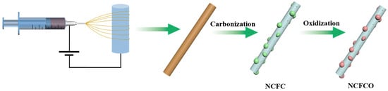
Figure 1.
Schematic diagram of the procedure for synthesizing the NCFCO.
2.1. Characterizations
For ECNF (Figure 2a), the carbon nanofibers present smooth surfaces, and interconnect with each other to form a disorder network architecture. Figure 2b displays the scanning electron microscopic (SEM) image of the NCFC, which also shows a nanofiber morphology with many Fe3C nanoparticles anchoring on the surface of the carbon nanofibers, to form an Fe3C/N-doped ECNF hybrid architecture. Compared with the morphology of the precursor after electrospinning (Figure S1), the nanofiber profile of the NCFC is well-reserved during the carbonization process, and additionally, Fe3C nanoparticles are generated from the aggregating of Fe atoms. The NCFCO reveals a similar profile to that of the NCFC (Figure 2c), suggesting that the carbon skeleton has not been destroyed after oxidizing at 200 °C. Nevertheless, when the temperature rises to 400 °C, only a few carbon nanofibers can be observed, owing to the fact that most of the carbon components are consumed through reacting with oxygen in the air at high temperatures (Figure 2d). Simultaneously, the Fe3C nanoparticles are completely oxidized to Fe2O3. Figure 2e–i show the elemental mappings of the NCFCO. Obviously, the C, O, and N elements are distributed evenly on the surface of the NCFCO, while the Fe spectroscopy mainly originates from the position of the nanoparticles, demonstrating that the nanoparticles located on the surface of carbon nanofibers are generated by the gathering of Fe atoms. The existence of the C, O, N, and Fe elements can also be proved using the energy-dispersive X-ray spectroscopy of the NCFCO (Figure S2). It is worth mentioning that the hybrid architecture of Fe3C/Fe2O3/NCNFs is developed through slow atom diffusion at a high temperature, which could greatly facilitate electron transfer, and prevent the structure of Fe2O3/Fe2O3 from being damaged during long-term cycling, owing to the tight connection between the heterogenous components.
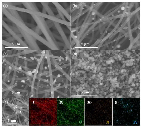
Figure 2.
SEM images of the (a) ECNF, (b) NCFC, (c) NCFCO, and (d) NCFO. SEM image (e) of the NCFCO and the corresponding elemental mappings of (f) C, (g) O, (h) N, and (i) Fe, respectively.
The crystal phases and compositions of the NCFC, NCFCO, and NCFO are identified by applying X-ray diffraction (XRD) patterns (Figure 3a) and Raman spectra (Figure 3b). It can be observed from Figure 3a that both the NCFC and NCFCO display obvious characteristic peaks at 37.9°, 39.8°, 40.7°, 43.0°, 43.9° 44.9°, 45.8°, 49.3°, and 70.8°, corresponding to the (210), (002), (201), (211), (102), (031), (112), (221), and (123) planes of Fe3C (JCPDS: no. 35-0772), respectively. Additionally, for the NCFCO and NCFO, apparent diffraction peaks at the angle of 24.1°, 33.1°, 35.6° 40.8°, 49.5°, 54.1°, 57.5°, 62.4°, and 64.0° can be observed, indexing to the (012), (104), (110), (113), (024), (116), (122), (214), and (300) planes of Fe2O3 (JCPDS: no. 33-0664). In particular, no Fe3C characteristic peaks can be detected, implying that all of the Fe3C has been oxidized to Fe2O3 in the NCFO. This can also be demonstrated using Raman spectroscopy. As revealed in Figure 3b, for the NCFC and NCFCO, two typical peaks, located at 1353 (D band) and 1590 cm−1 (G band), can be assigned to the disorder and sp2 hybridized carbon atoms in the carbon lattice, respectively [32,33]. Furthermore, the slight peaks at about 224, 294, and 393 cm−1 belong to the Ag1, Eg2 + Eg3, and Eg4 modes of Fe2O3, respectively [34]. The above results prove that the NCFCO consists of Fe3C, Fe2O3, and amorphous carbon. The Raman spectroscopy of the NCFO displays sharp peaks at around 224, 294, and 393 cm−1, demonstrating the existence of Fe2O3, which is in accordance with its XRD result.
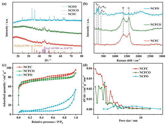
Figure 3.
The (a) XRD patterns, (b) Raman spectroscopy, (c) N2 adsorption–desorption isotherms, and (d) pore size distribution of the NCFC, NCFCO, and NCFO.
The N2 adsorption–desorption isotherms (Figure 3c) were recorded, to investigate the porous character of the samples. As can be seen, all of the samples display type-IV isotherms, demonstrating the existence of mesopores in these hybrid architectures [35]. Additionally, the sharp uptake in the low relative pressure region suggests an abundant micropore content in the NCFC and NCFCO, and the steep slope in the high relative pressure zone is owing to the existence of macropores [36]. The pore-size distribution curves (Figure 3d) also prove the presence of micropores and mesopores in the samples. Therefore, both the NCFC and NCFCO are hierarchical pore architectures. Generally, micropores are the significant architecture to store ions, and mesopores can facilitate ion transfer and migration, whereas macropores are efficient buffer regions for electrolyte ions. Therefore, the hierarchically porous structure in the NCFCO is beneficial to realizing a superior electrochemical performance. The SSA, pore volume, and average pore diameter of the NCFC, NCFCO, and NCFO are summarized in Table S1. Clearly, as the calcined temperature increases, the SSA and pore volume are all decreasing, which is likely due to the fact that more carbon components are drained at higher temperatures, thus leaving a larger average pore diameter.
The surface elemental valences and chemical compositions of the NCFC, NCFCO, and NCFO were researched by applying X-ray photoelectron spectroscopy (XPS). The XPS survey spectra of the samples are presented in Figure 4a. As can be clearly seen, there are C1s, O1s, and Fe2p peaks at around 286, 530, and 723 eV, respectively. Compared with the NCFO, both the NCFC and NCFCO exhibit apparent N1s peaks at the binding energy of about 400 eV, which is likely due to fewer NCNFs having been retained in the NCFO after oxidization at the higher temperature of 400 °C. The detailed elemental contents of the NCFC, NCFCO, and NCFO are listed in Table 1. Clearly, as the calcined temperature increases, more carbon components are consumed, while the Fe atoms are reserved in the form of Fe-based oxide/carbide. The high-resolution C1 spectra (Figure S3) of the NCFC, NCFCO, and NCFO can be deconvoluted into four peaks, centered at 284.2, 285.9, 286.9, and 288.7 eV, which can be assigned to the C–C/C=C, C–O, C–N/C=N, and O–C=O bonds [37,38], respectively. Additionally, for the NCFC, the peak at the binding energy of 283.5 eV can be clearly observed, corresponding with the Fe–C bond. The N1s spectra (Figure 4b and Figure S4) could be segmented into the pyridinic N (N–6), pyrrolic N (N–5), graphitic N (N–Q), and oxidic N (N–X), situated at 397.7, 398.4, 400.0, and 401.3 eV, respectively, indicating that the N atoms were successfully doped into the carbon lattice, with different bonding modes [39]. It is worth mentioning that the N–Q is beneficial in enhancing the conductivity of the carbon matrix, and therefore in improving its electrochemical performance [23,40]. Furthermore, the N–6 and N–5 species can contribute effective pseudocapacitance during the charge–discharge process, as well [29,41]. In the deconvoluted O1 spectra presented in Figure 4c and Figure S5, four peaks, located at 529.8, 531.1, 532.6, and 533.3 eV, can be ascribed to the Fe–O, C=O, C–O, and C–OOH species [13,36,42], respectively. Figure 4d and Figure S6 show the high-resolution Fe2p spectra. The photoelectron peaks at 710.7 and 723.6 eV correspond to the Fe2+2p3/2 and Fe2+2p1/2 orbitals, while the peaks at 714.1 and 726.6 eV belong to the Fe3+2p3/2 and Fe3+2p1/2 orbitals [43], respectively. Meanwhile, two accompanying shake-up satellite peaks at 719.2 and 731.8 eV can also be observed [44].
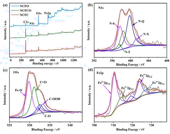
Figure 4.
The (a) XPS survey spectra of the NCFC, NCFCO, and NCFO. The high-resolution (b) C1, (c) N1, and (d) Fe2p peaks of the NCFCO.

Table 1.
The atomic contents of the NCFC, NCFCO, and NCFO.
2.2. Electrochemical Measurements
The electrochemical performances of the NCFC, NCFCO, and NCFO are detected using electrochemical impedance spectroscopy (EIS), cyclic voltammetry (CV), and galvanostatic charge–discharge (GCD) techniques in 2 mol L−1 KOH electrolyte, and the results are revealed in Figure 5. As presented, all of the EIS spectra (Figure 5a) display approximate straight lines in the low frequency region, indicating a superior capacitive property [45,46]. The charge transfer resistances (Rct) of the as-prepared samples are fitted by means of the equivalent circuit (inset of Figure 5a). As expected, the NCFCO exhibits the smallest Rct (1.2 Ω), compared to those of the NCFC (15.7 Ω) and NCFO (36.3 Ω), indicating the fastest electrode reaction kinetics. Such a result can be attributed to its large SSA, enlarged pore volume, and the synergistic effects between the Fe3C/Fe2O3 and the residual carbon skeleton. Additionally, it can be found that the equivalent series resistances (Rs) of the samples increase with the increasing oxidization temperature (in the inset of Figure 5a), owing to the fact that fewer carbon atoms can be reserved at higher calcination temperatures (Table 1).
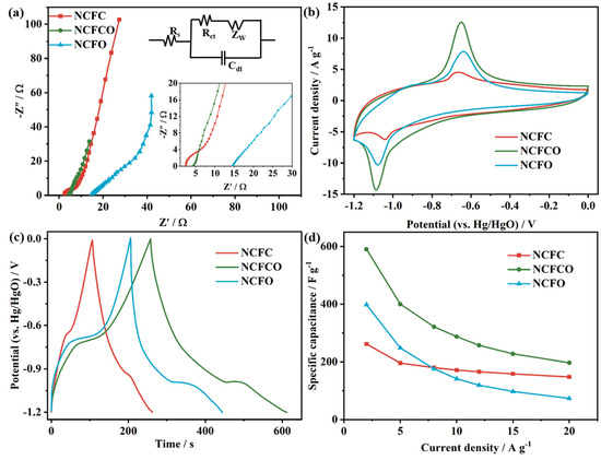
Figure 5.
The (a) Nyquist spectra (inset shows the high-resolution plots in the low frequency region and the equivalent circuit), (b) CV curves at 10 mV s−1, (c) GCD plots at 2 A g−1, and (d) specific capacitance vs. current density plots of the NCFC, NCFCO, and NCFO.
Figure 5b compares the CV curves of the NCFC, NCFCO, and NCFO at 10 mV s−1. Clearly, all of the CV curves exhibit prominent anodic and cathodic peaks at about −0.7 V and −1.1 V, respectively, which is similar to other Fe-based oxides/carbides [47,48], indicating a dominant Faradic charge storage behavior introduced by the conversion between Fe2+ and Fe3+, according to the following reaction equations [13,49]:
Fe2O3 + 2e− + 3H2O ⇌ 2Fe(OH)2 + 2OH−
Fe3O4 + 2e− + 4H2O ⇌ 3Fe(OH)2 + 2OH−
Herein, the Fe3O4 species should be generated through the electrochemically induced activation of Fe3C, during the initial charge–discharge process [14]. Compared to the NCFC and NCFO, the CV curve of the NCFCO exhibits the largest integral area, and prominent redox peaks, proving the highest specific capacitance and rapid redox reaction kinetics, respectively. Additionally, the anodic and cathodic peaks in the CV curves (Figure S7) shift to a more negative and positive region with the increasing scan rate. Such results could be ascribed to the polarization originating from the accumulation of ions with the increment of the scan rate. Furthermore, the apparent anodic and cathodic peaks at the scan rates from 5 to 100 mV s−1 can be clearly observed (Figure S7), demonstrating a significant pseudocapacitive behavior in terms of Equations (1) and (2), and the superior capacitive performance of the NCFC, NCFCO, and NCFO. The CV curves of AC (Figure S8) display approximately rectangular shapes at different scan rates, revealing the dominant EDLC behavior.
The GCD profiles at 2 A g−1 are compared in Figure 5c. As presented, the nonlinear GCD plots with apparent voltage platforms at around −0.7 and −1.1 V confirm the significant Faradic reactions of the products, which are consistent with their CV results. Additionally, the longest discharge time of the NCFCO reveals its maximum specific capacitance. The GCD plots at diverse current densities display apparent potential plateaus (Figure S9), verifying the excellent electrochemical reversibility and capacitive property. The GCD curves of AC (Figure S10) show nearly-isosceles-triangle-shaped profiles at any current density, which is a typical feature of the EDLC. Figure 5d displays the specific capacitance vs. current density plots of the samples. As seen, the specific capacitance reduces with the increase in the current density, as a result of the active sites being unable to complete the necessary number of redox conversions and ion migrations during the rapid charge–discharge process. Furthermore, the NCFCO delivers the specific capacitance of 590.1 F g−1 at 2 A g−1, superior to that of the NCFC (261.7 F g−1) and NCFO (398.3 F g−1), and it remains at 196.7 F g−1 at 20 A g−1, exhibiting a good rate capability. The comparisons of our NCFCO and the previously reported Fe-based oxides/carbides are listed in Table S2. Clearly, our NCFCO exhibits an outstanding specific capacitance, which is likely derived from the unique hybrid architecture of the Fe3C/Fe2O3/N-doped ECNF composite.
An asymmetric SC device was assembled using the NCFCO anode and AC cathode, and its electrochemical performance was investigated in a two-electrode system. The CV plots of the NCFCO//AC device at diverse scan rates are recorded in Figure 6a. As revealed, the remarkable redox peaks in the CV curves can be attributed to the Faradic reactions of Fe2O3 and Fe3O4 species, according to Equations (1) and (2). Furthermore, no apparent deformation can be observed, even at high scan rates, proving the excellent capacitive performance. In agreement with the CV results, the nonlinear GCD profiles (Figure 6b) of the asymmetric device at different current densities display evident anodic and cathodic platforms in the charging and discharging steps, respectively, which further confirm the existence of Faradic reactions. The specific capacitances of the NCFCO//AC device derived from the GCD results are calculated and plotted in Figure 6c. Specifically, a high specific capacitance of 40 F g−1 at 1 A g−1 is achieved, and is maintained at 12.5 F g−1 (31.3% of the initial value) at 20 A g−1. In order to investigate the maximum working voltage window of the as-assembled NCFCO//AC, the CV curves at 10 mV s−1 under various voltage windows are recorded and displayed in Figure 6d. Clearly, the stable operating voltage window can extend to 1.9 V without any irreversible oxygen/hydrogen evolution reactions occurring. Generally, the cycling stability is also a crucial performance indicator for an SC. As depicted in Figure 6e, the specific capacitance can still retain 96.7% of the original value after 10,000 cycles at a current density of 10 A g−1, and the last ten GCD cycles display negligible change compared to the first ten GCD cycles. Compared to the initial morphology (Figure S11a) of the NCFCO electrode, almost no structural destructions can be observed after 5000 (Figure S11b) and 10,000 (Figure S11c) charge–discharge cycles, which further confirms that the Fe3C/Fe2O3 nanoparticles are tightly anchored on the N–doped ECNFs, to form a robust hybrid architecture. Meanwhile, the corresponding charge efficiency can still maintain 100% after long-cycling, confirming the excellent energy transmission capability. Such results demonstrate the excellent cycling stability and reversibility of the asymmetric NCFCO//AC device.
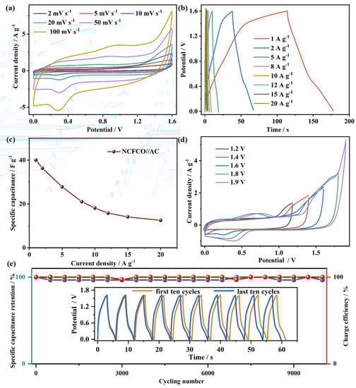
Figure 6.
The (a) CV curves, (b) GCD plots, (c) specific capacitance vs. current density plot, (d) CV curves at 10 mV s−1 with diverse voltage windows, and (e) cyclic stability and corresponding charge efficiency (inset shows the first and last ten GCD cycles) of the NCFCO//AC device.
Figure 7 presents the Ragone plot of the NCFCO//AC device. Clearly, this asymmetric SC exhibits a competitive energy density of 14.2 Wh kg−1 at 800 W kg−1, and still remains 5 Wh kg−1 at 12,000 W kg−1, which is higher than some of the Fe-based SCs, such as NiCo2S4/graphene//Fe2O3/graphene (5 Wh kg−1 at 595 W kg−1) [50], NiO//Fe2O3 (12.4 Wh kg−1 at 951 W kg−1) [51], Fe2O3//Fe2O3 (4.2 Wh kg−1 at 224.9 W kg−1) [52], NiO@N-doped carbon nanoarrays/carbon cloth//Fe2O3@N–doped carbon nanoarray/carbon cloth (12.23 Wh kg−1 at 307.69 W kg−1) [25], and Fe3O4/N–doped carbon nanosheet/carbon nanotube (11 Wh kg−1 at 2500 W kg−1) [53]. The outstanding electrochemical energy storage performance of our NCFCO makes it a superior candidate for high-performance SCs.
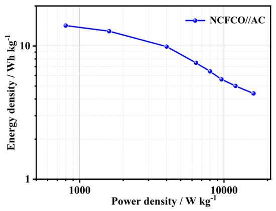
Figure 7.
The Ragone plot of the NCFCO//AC device.
3. Experimental
3.1. Chemicals and Regents
N-dimethylformamide (DMF, AR), potassium hydroxide (KOH, AR), polyacrylonitrile (PAN, Mw = 150,000, Sigma-Aldrich, Shanghai, China), iron acetylacetonate (IAA, AR), and N-methylpyrrolidone (NMP, AR) were all bought from Sinopharm Chemical Reagent Co., Ltd. (Shanghai, China), and used as received. AC was bought from Jiangsu Xianfeng Nanomaterial Technology Co., Ltd. (Nanjing, China). The deionization water used in this work was fabricated using an ultrapure water system.
3.2. Preparations of the NCFC, NCFCO, and NCFO
The schematic illustrations of the preparation procedures for the NCFCO are displayed in Figure 1. Typically, 0.6 g IAA was added into 4.5 g DMF, and stirred for 1 h at room temperature, to prepare a homogeneous solution. After that, 0.5 g PAN was dissolved into the above solution, and stirred at 60 °C for 6 h, to form a uniform spinning solution. Immediately, electrospinning was conducted using an applied voltage of 12 kV, with a flow rate of 0.7 mL h−1, at room temperature. Next, the as-obtained nanofiber precursor was collected, and then carbonized at 800 °C (5 °C min−1) for 2 h in a N2 atmosphere. The as-prepared sample was named as the NCFC. Finally, the NCFC was individually oxidized at 200 °C (5 °C min−1) and 400 °C (5 °C min−1) in air for 2 h, to fabricate the NCFCO and NCFO, respectively. For comparison, ECNFs were also prepared using a similar procedure to that of the NCFC, except for the addition of IAA. The samples and corresponding preparation conditions are listed in Table S3.
The electrochemical measurements and characterizations applied in this work are shown in the Supporting Information.
4. Conclusions
In summary, a N-doped-ECNF-supported Fe3C/Fe2O3 nanoparticle hybrid architecture composite was successfully synthesized through a facile electrospinning and subsequent thermal treatment strategy. The optimized hybrid architecture, with a large SSA, endows the NCFCO with low charge transfer resistance, and fast redox kinetics. Relying on the synergistic contributions of the Fe3C/Fe2O3 nanoparticles and NCNFs, the as-obtained NCFCO shows the high specific capacitance of 590.1 F g−1 at 2 A g−1. The asymmetric SC device based on the NCFCO anode and AC cathode can output a high energy density of 14.2 Wh kg−1 at 800 W kg−1. Furthermore, it also displays long-term cycling stability, with only a 3.3% capacitance decay after 10,000 cycles. Our work demonstrates a facile process to construct Fe-based oxides/carbides/NCNFs for SCs.
Supplementary Materials
The following supporting information can be downloaded at: https://www.mdpi.com/article/10.3390/molecules28155751/s1, Figure S1: (a) Low and (b) high magnification SEM images of the electrospinning nanofiber precursor before annealing.; Figure S2: EDS spectrum of NCFCO; Figure S3: High resolution C1s spectra of (a) NCFC, (b) NCFCO, and (c) NCFO; Figure S4: High resolution N1s spectra of (a) NCFC and (b) NCFO; Figure S5: High resolution O1s spectra of (a) NCFC and (b) NCFO; Figure S6: High resolution Fe2p spectra of (a) NCFC and (b) NCFO; Figure S7: CV curves of (a) NCFC, (b) NCFCO, and (c) NCFO at different scan rates; Figure S8: CV curves of AC at different scan rates; Figure S9: GCD curves of (a) NCFC, (b) NCFCO, and (c) NCFO at different current densities; Figure S10: GCD plots of AC at different current densities; Figure S11: SEM images of NCFCO electrode (a) before and after (b) 5000 and (c) 10,000 charge-discharge cycles; Table S1: SSA, pore volume, and average pore diameter of NCFC, NCFCO, and NCFO; Table S2: Specific capacitances of NCFCO and previously reported Fe-based oxides/carbides; Table S3: Preparation conditions of NCFC, NCFCO, and NCFO. References [14,18,44,53,54,55,56,57,58,59] are cited in the Supplementary Materials.
Author Contributions
Investigation, Data curation, Writing–original draft, L.L.; Investigation, Data curation, F.X.; Data curation, Validation, H.W.; Methodology, Y.Z.; Supervision, Validation, P.Z.; Supervision, Y.L.; Writing–review & editing, H.L.; Validation, L.Z.; Conceptualization, Funding acquisition, G.Z. All authors have read and agreed to the published version of the manuscript.
Funding
This research was funded by [the Natural Science Foundation of Anhui Province] grant number [2008085QE204], [the Key Teaching and Scientific Research Project of Suzhou University] grant number [2020yzd08], [the Natural Science Research Key Project of Anhui Provincial Department of Education] grant number [KJ2020A0727, KJ2019A0674], [the Natural Science Research Project in the Universities of Anhui Province] grant number [2022AH051386], [the Support Program for Excellent Young Talents in the Universities of Anhui Province] grant number [2022AH030134], [the Doctoral Research Initiation Fund Project of Suzhou University] grant number [2019jb24, 2020BS020], [the Scientific Research and Development Fund Project of Suzhou University] grant number [2021fzjj16], and [the Provincial of the Anhui Scientific Research Innovation Team of Photoelectric Information Materials and New Energy Devices] grant number [2016SCXPTTD].
Institutional Review Board Statement
Not applicable.
Informed Consent Statement
Not applicable.
Data Availability Statement
Not applicable.
Acknowledgments
We gratefully acknowledge the financial support.
Conflicts of Interest
The authors declare no conflict of interest.
Sample Availability
Samples of the NCFC, NCFCO and NCFO are available from the authors.
References
- Li, X.; Lou, D.; Wang, H.; Sun, X.; Li, J.; Liu, Y.N. Flexible supercapacitor based on organohydrogel electrolyte with long-term anti-freezing and anti-drying property. Adv. Funct. Mater. 2020, 30, 2007291. [Google Scholar] [CrossRef]
- Li, C.; Wang, S.; Cui, Y.; Wang, X.; Yong, Z.; Liang, D.; Chi, Y.; Wang, Z. Sandwich-like MXene/alpha-Fe2O3-C-MoS2-PEDOT:PSS/MXene film electrodes with ultrahigh area capacitance for flexible supercapacitors. ACS Appl. Mater. Interfaces 2022, 14, 9172–9182. [Google Scholar] [CrossRef] [PubMed]
- Liu, Y.; Xu, X.; Shao, Z.; Jiang, S.P. Metal-organic frameworks derived porous carbon, metal oxides and metal sulfides-based compounds for supercapacitors application. Energy Storage Mater. 2020, 26, 1–22. [Google Scholar] [CrossRef]
- He, Y.; Wei, Q.; An, N.; Meng, C.; Hu, Z. Organic small-molecule electrodes: Emerging organic composite materials in supercapacitors for efficient energy storage. Molecules 2022, 27, 7692. [Google Scholar] [CrossRef] [PubMed]
- Ahn, K.-S.; Vinodh, R.; Pollet, B.G.; Babu, R.S.; Ramkumar, V.; Kim, S.-C.; Krishnakumar, K.; Kim, H.-J. A high-performance asymmetric supercapacitor consists of binder free electrode materials of bimetallic hydrogen phosphate (MnCo(HPO4)) hexagonal tubes and graphene ink. Electrochim. Acta 2022, 426, 140763. [Google Scholar] [CrossRef]
- Li, B.; Yu, M.; Li, Z.; Yu, C.; Wang, H.; Li, Q. Constructing flexible all-solid-state supercapacitors from 3D nanosheets active bricks via 3D manufacturing technology: A perspective review. Adv. Funct. Mater. 2022, 32, 2201166. [Google Scholar] [CrossRef]
- Zhao, G.; Li, Y.; Zhu, G.; Shi, J.; Lu, T.; Pan, L. Biomass-based N, P, and S self-doped porous carbon for high-performance supercapacitors. ACS Sustain. Chem. Eng. 2019, 7, 12052–12060. [Google Scholar] [CrossRef]
- Qiu, H.; Cheng, H.; Meng, J.; Wu, G.; Chen, S. Magnetothermal microfluidic-assisted hierarchical microfibers for ultrahigh-energy-density supercapacitors. Angew. Chem. Int. Ed. 2020, 59, 7934–7943. [Google Scholar] [CrossRef]
- Roy, B.K.; Tahmid, I.; Rashid, T.U. Chitosan-based materials for supercapacitor applications: A review. J. Mater. Chem. A 2021, 9, 17592–17642. [Google Scholar] [CrossRef]
- Zhang, D.; Tan, C.; Zhang, W.; Pan, W.; Wang, Q.; Li, L. Expanded graphite-based materials for supercapacitors: A review. Molecules 2022, 27, 716. [Google Scholar] [CrossRef]
- Zhu, Y.; Ji, X.; Yang, L.; Jia, J.; Cheng, S.; Chen, H.; Wu, Z.-S.; Passarello, D.; Liu, M. Targeted synthesis and reaction mechanism discussion of Mo2C based insertion-type electrodes for advanced pseudocapacitors. J. Mater. Chem. A 2020, 8, 7819–7827. [Google Scholar] [CrossRef]
- Huang, J.; Xie, Y.; You, Y.; Yuan, J.; Xu, Q.; Xie, H.; Chen, Y. Rational design of electrode materials for advanced supercapacitors: From lab research to commercialization. Adv. Funct. Mater. 2023, 33, 2213095. [Google Scholar] [CrossRef]
- Liu, H.; Zhu, J.; Li, Z.; Shi, Z.; Zhu, J.; Mei, H. Fe2O3/N doped rGO anode hybridized with NiCo LDH/Co(OH)2 cathode for battery-like supercapacitor. Chem. Eng. J. 2021, 403, 126325. [Google Scholar] [CrossRef]
- Chen, L.; Liang, B.; Lv, J.; Chen, M.; Hu, J.; Zeng, K.; Yang, G. Route to a porous carbon nanofiber membrane containing FexCy/Fe by facile in situ ion-exchange functionalization of the PAA carboxyl group: Exemplified by a supercapacitor. ACS Appl. Energy Mater. 2022, 5, 1580–1594. [Google Scholar] [CrossRef]
- Wang, Y.; Du, Z.; Xiao, J.; Cen, W.; Yuan, S. Polypyrrole-encapsulated Fe2O3 nanotube arrays on a carbon cloth support: Achieving synergistic effect for enhanced supercapacitor performance. Electrochim. Acta 2021, 386, 138486. [Google Scholar] [CrossRef]
- Zhu, Y.; Cheng, S.; Zhou, W.; Jia, J.; Yang, L.; Yao, M.; Wang, M.; Zhou, J.; Wu, P.; Liu, M. Construction and performance characterization of α-Fe2O3/rGO composite for long-cycling-life supercapacitor anode. ACS Sustain Chem. Eng. 2017, 5, 5067–5074. [Google Scholar] [CrossRef]
- Jiang, S.-H.; Ding, J.; Wang, R.-H.; Chen, F.-Y.; Sun, J.; Deng, Y.-X.; Li, X.-L. Solvothermal-induced construction of ultra-tiny Fe2O3 nanoparticles/graphene hydrogels as binder-free high-capacitance anode for supercapacitors. Rare Met. 2021, 40, 3520–3530. [Google Scholar] [CrossRef]
- Shi, T.-Z.; Feng, Y.-L.; Peng, T.; Yuan, B.-G. Sea urchin-shaped Fe2O3 coupled with 2D MXene nanosheets as negative electrode for high-performance asymmetric supercapacitors. Electrochim. Acta 2021, 381, 138245. [Google Scholar] [CrossRef]
- Wu, C.; Zhang, Z.; Chen, Z.; Jiang, Z.; Li, H.; Cao, H.; Liu, Y.; Zhu, Y.; Fang, Z.; Yu, X. Rational design of novel ultra-small amorphous Fe2O3 nanodots/graphene heterostructures for all-solid-state asymmetric supercapacitors. Nano Res. 2020, 14, 953–960. [Google Scholar] [CrossRef]
- Hu, B.; Wang, Y.; Shang, X.; Xu, K.; Yang, J.; Huang, M.; Liu, J. Structure-tunable Mn3O4-Fe3O4@C hybrids for high-performance supercapacitor. J. Colloid. Interf. Sci. 2021, 581, 66–75. [Google Scholar] [CrossRef]
- Wang, Y.; Xiao, J.; Zhang, T.; Ouyang, L.; Yuan, S. Single-step preparation of ultrasmall iron oxide-embedded carbon nanotubes on carbon cloth with excellent superhydrophilicity and enhanced supercapacitor performance. ACS Appl. Mater. Interfaces 2021, 13, 45670–45678. [Google Scholar] [CrossRef]
- Li, Y.; Liu, Y.; Wang, M.; Xu, X.; Lu, T.; Sun, C.Q.; Pan, L. Phosphorus-doped 3D carbon nanofiber aerogels derived from bacterial-cellulose for highly-efficient capacitive deionization. Carbon 2018, 130, 377–383. [Google Scholar] [CrossRef]
- Feng, X.; Bai, Y.; Liu, M.; Li, Y.; Yang, H.; Wang, X.; Wu, C. Untangling the respective effects of heteroatom-doped carbon materials in batteries, supercapacitors and the ORR to design high performance materials. Energy Environ. Sci. 2021, 14, 2036–2089. [Google Scholar] [CrossRef]
- Tong, Y.; Yang, J.; Li, J.; Cong, Z.; Wei, L.; Liu, M.; Zhai, S.; Wang, K.; An, Q. Lignin-derived electrode materials for supercapacitor applications: Progress and perspectives. J. Mater. Chem. A 2023, 11, 1061–1082. [Google Scholar] [CrossRef]
- Cai, D.; Du, J.; Zhu, C.; Cao, Q.; Huang, L.; Wu, J.; Zhou, D.; Xia, Q.; Chen, T.; Guan, C.; et al. Iron oxide nanoneedles anchored on N-doped carbon nanoarrays as an electrode for high-performance hybrid supercapacitor. ACS Appl. Energ. Mater. 2020, 3, 12162–12171. [Google Scholar] [CrossRef]
- Kang, M.; Zhou, S.; Zhang, J.; Ning, F.; Ma, C.; Qiu, Z. Facile fabrication of oxygen vacancy-rich α-Fe2O3 microspheres on carbon cloth as negative electrode for supercapacitors. Electrochim. Acta 2020, 338, 135820. [Google Scholar] [CrossRef]
- Yan, Y.; Liu, X.; Yan, J.; Guan, C.; Wang, J. Electrospun nanofibers for new generation flexible energy storage. Energy Environ. Mater. 2020, 4, 502–521. [Google Scholar] [CrossRef]
- Tong, Z.; Huang, L.; Lei, W.; Zhang, H.; Zhang, S. Carbon-containing electrospun nanofibers for lithium-sulfur battery: Current status and future directions. J. Energy Chem. 2021, 54, 254–273. [Google Scholar] [CrossRef]
- Li, Y.; Zhu, G.; Xu, X.; Chen, L.; Lu, T.; Hill, J.P.; Pan, L.; Yamauchi, Y. Embedding metal-organic frameworks for the design of flexible hybrid supercapacitors by electrospinning: Synthesis of highly graphitized carbon nanofibers containing metal oxide nanoparticles. Small Struct. 2022, 3, 2200015. [Google Scholar] [CrossRef]
- Wang, H.; Yao, L.; Zuo, H.; Ruan, F.; Wang, H. Fabrication of porous carbon nanofibers from polymer blends using template method for electrode-active materials in supercapacitor. Molecules 2023, 28, 2228. [Google Scholar] [CrossRef]
- Zhang, X.; Han, R.; Liu, Y.; Li, H.; Shi, W.; Yan, X.; Zhao, X.; Li, Y.; Liu, B. Porous and graphitic structure optimization of biomass-based carbon materials from 0D to 3D for supercapacitors: A review. Chem. Eng. J. 2023, 460, 141607. [Google Scholar] [CrossRef]
- Dong, K.; Liang, J.; Wang, Y.; Xu, Z.; Liu, Q.; Luo, Y.; Li, T.; Li, L.; Shi, X.; Asiri, A.M.; et al. Honeycomb carbon nanofibers: A superhydrophilic O2-entrapping electrocatalyst enables ultrahigh mass activity for the two-electron oxygen reduction reaction. Angew. Chem. Int. Ed. 2021, 60, 10583–10587. [Google Scholar] [CrossRef] [PubMed]
- Wang, Z.; Feng, X.; Bai, Y.; Yang, H.; Dong, R.; Wang, X.; Xu, H.; Wang, Q.; Li, H.; Gao, H.; et al. Probing the energy storage mechanism of quasi-metallic Na in hard carbon for sodium-ion batteries. Adv. Energy Mater. 2021, 11, 2003854. [Google Scholar] [CrossRef]
- Gao, W.; Li, Y.; Zhao, J.; Zhang, Z.; Tang, W.; Wang, J.; Wu, Z.; Li, Z. Design and preparation of graphene/Fe2O3 nanocomposite as negative material for supercapacitor. Chem. Res. Chin. Univ. 2022, 38, 1097–1104. [Google Scholar] [CrossRef]
- Su, X.; Ye, C.; Li, X.; Guo, M.; Cao, R.; Ni, K.; Zhu, Y. Heterogeneous stacking carbon films for optimized supercapacitor performance. Energy Storage Mater. 2022, 50, 365–372. [Google Scholar] [CrossRef]
- Hou, X.; Ren, P.; Dai, Z.; Chen, H.; Tang, W.; Chen, Z.; Ren, F.; Jin, Y. Ultrahigh voltage window, preeminent energy density aqueous supercapacitor derived from honeycomb-like porous carbon decorated with carbon dots. Electrochim. Acta 2022, 425, 140336. [Google Scholar] [CrossRef]
- Goswami, R.N.; Mourya, P.; Behera, B.; Khatri, O.P.; Ray, A. Graphene-polyaniline nanocomposite based coatings: Role of convertible forms of polyaniline to mitigate steel corrosion. Appl. Surf. Sci. 2022, 599, 153939. [Google Scholar] [CrossRef]
- Wang, H.; Chen, J.; Wang, P.; Liang, C.; Yu, K. Preparation and mechanism of biomass-derived graphene-like Li+/Na+ battery anodes controlled by N/O functional groups and interlayer spacing. J. Alloys Compd. 2022, 918, 165785. [Google Scholar] [CrossRef]
- Wee, J.-H.; Kim, Y.A.; Yang, C.-M. Sequential doping of nitrogen and oxygen in single-walled carbon nanohorns for use as supercapacitor electrodes. Micropor. Mesopor. Mater. 2021, 310, 110595. [Google Scholar] [CrossRef]
- Wang, M.; Yang, J.; Liu, S.; Che, X.; He, S.; Chen, G.; Qiu, J. Nitrogen-doped porous carbon electrode for aqueous iodide redox supercapacitor. Chem. Eng. J. 2023, 451, 138501. [Google Scholar] [CrossRef]
- Sun, Y.; Xu, D.; Wang, S. Self-assembly of biomass derivatives into multiple heteroatom-doped 3D-interconnected porous carbon for advanced supercapacitors. Carbon 2022, 199, 258–267. [Google Scholar] [CrossRef]
- Ji, Z.; Tang, G.; Ma, D.; Chen, L.; Zhu, G.; Zhu, J.; Shen, X. Phosphate functionalized CoS nanoparticles coupled with Fe2O3 nanocrystals decorated on N, S co-doped porous carbon spheres for advanced hybrid supercapacitors. Inorg. Chem. Front. 2023, 10, 406–416. [Google Scholar] [CrossRef]
- Zhou, C.; Li, X.; Jiang, H.; Ding, Y.; He, G.; Guo, J.; Chu, Z.; Yu, G. Pulverizing Fe2O3 nanoparticles for developing Fe3C/N-codoped carbon nanoboxes with multiple polysulfide anchoring and converting activity in Li-S batteries. Adv. Funct. Mater. 2021, 31, 2011249. [Google Scholar] [CrossRef]
- Cheng, J.; Wu, D.; Wang, T. N-doped carbon nanosheet supported Fe2O3/Fe3C nanoparticles as efficient electrode materials for oxygen reduction reaction and supercapacitor application. Inorg. Chem. Commun. 2020, 117, 107952. [Google Scholar] [CrossRef]
- Zhang, T.; Liu, P.; Zhong, Y.; Zheng, J.; Deng, K.; Lv, X.; Li, H.; Tian, W.; Ji, J. N, S co-doped branched carbon nanotubes with hierarchical porous structure and electron/ion transfer pathways for supercapacitors and lithium-ion batteries. Carbon 2022, 198, 91–100. [Google Scholar] [CrossRef]
- Zhang, S.; Li, B.; Cui, C.; Qian, W.; Jin, Y. The progress and comprehensive analysis of supercapacitors for alternating current line filtering: A review. Batter. Supercaps 2023, 6, 202200566. [Google Scholar] [CrossRef]
- Dai, S.; Bai, Y.; Shen, W.; Zhang, S.; Hu, H.; Fu, J.; Wang, X.; Hu, C.; Liu, M. Core-shell structured Fe2O3@Fe3C@C nanochains and Ni-Co carbonate hydroxide hybridized microspheres for high-performance battery-type supercapacitor. J. Power Source 2021, 482, 228915. [Google Scholar] [CrossRef]
- Wang, S.; Wang, S.; Guo, X.; Wang, Z.; Mao, F.; Su, L.; Wu, H.; Wang, K.; Zhang, Q. An asymmetric supercapacitor with an interpenetrating crystalline Fe-MOF as the positive electrode and its congenetic derivative as the negative electrode. Inorg. Chem. Front. 2021, 8, 4878–4886. [Google Scholar] [CrossRef]
- Zhang, Y.; Shao, R.; Xu, W.; Ding, J.; Wang, Y.; Yan, X.; Shi, W.; Wang, M. Soluble salt assisted synthesis of hierarchical porous carbon-encapsulated Fe3C based on MOFs gel for all-solid-state hybrid supercapacitor. Chem. Eng. J. 2021, 419, 129576. [Google Scholar] [CrossRef]
- Guo, R.; Dang, L.; Liu, Z.; Lei, Z. Incorporation of electroactive NiCo2S4 and Fe2O3 into graphene aerogel for high-energy asymmetric supercapacitor. Colloids Surf. A 2020, 602, 125110. [Google Scholar] [CrossRef]
- Zhang, S.; Yin, B.; Wang, Z.; Peter, F. Super long-life all solid-state asymmetric supercapacitor based on NiO nanosheets and α-Fe2O3 nanorods. Chem. Eng. J. 2016, 306, 193–203. [Google Scholar] [CrossRef]
- Lu, P.A.; Manikandan, M.R.; Yang, P.F.; He, Y.L.; Yang, F.; Dang, S.T.; Shi, Y.C.; Lou, W.B.; Liu, R.; Wu, S.J.; et al. Synthesis, analysis and characterization of alpha-Fe2O3 nanoparticles and their applications in supercapacitors. J. Mater. Sci. Mater. Electron. 2023, 34, 826. [Google Scholar] [CrossRef]
- Li, L.; Jia, C.; Shao, Z.; Wang, J.; Wang, F.; Wang, W.; Wang, H.; Zu, D.; Wu, H. Fe3O4/nitrogen-doped carbon electrodes from tailored thermal expansion toward flexible solid-state asymmetric supercapacitors. Adv. Mater. Interfaces 2019, 6, 1901250. [Google Scholar] [CrossRef]
- Peng, Z.; Huang, J.; Wang, Y.; Yuan, K.; Tan, L.; Chen, Y. Construction of a hierarchical carbon coated Fe3O4 nanorod anode for 2.6 V aqueous asymmetric supercapacitors with ultrahigh energy density. J. Mater. Chem. A 2019, 7, 27313–27322. [Google Scholar] [CrossRef]
- Su, S.; Lai, L.; Li, R.; Lin, Y.; Dai, H.; Zhu, X. Annealing-assisted dip-coating synthesis of ultrafine Fe3O4 nanoparticles/graphene on carbon cloth for flexible quasi-solid-state symmetric supercapacitors. ACS Appl. Energy Mater. 2020, 3, 9379–9389. [Google Scholar] [CrossRef]
- Zhang, M.; Wu, X.; Yang, D.; Qin, L.; Zhang, S.; Xu, T.; Zhao, T.; Yu, Z.-Z. Ultraflexible reedlike carbon nanofiber membranes decorated with Ni-Co-S nanosheets and Fe2O3-C core-shell nanoneedle arrays as electrodes of flexible quasi-solid-state asymmetric supercapacitors. ACS Appl. Energy Mater. 2021, 4, 1505–1516. [Google Scholar] [CrossRef]
- Luo, Y.; Tang, Y.; Bin, X.; Xia, C.; Que, W. 3D porous compact 1D/2D Fe2O3/MXene composite aerogel film electrodes for all-solid-state supercapacitors. Small 2022, 18, 2204917. [Google Scholar] [CrossRef]
- Kumar, A.; Das, D.; Sarkar, D.; Patil, S.; Shukla, A. Supercapacitors with prussian blue derived carbon encapsulated Fe/Fe3C nanocomposites. J. Electrochem. Soc. 2020, 167, 060529. [Google Scholar] [CrossRef]
- Khalafallah, D.; Miao, J.; Zhi, M.; Hong, Z. Confining self-standing CoSe2 nanostructures and Fe3C wrapped N-doped carbon frameworks with enhanced energy storage performances. Appl. Surf. Sci. 2021, 564, 150449. [Google Scholar] [CrossRef]
Disclaimer/Publisher’s Note: The statements, opinions and data contained in all publications are solely those of the individual author(s) and contributor(s) and not of MDPI and/or the editor(s). MDPI and/or the editor(s) disclaim responsibility for any injury to people or property resulting from any ideas, methods, instructions or products referred to in the content. |
© 2023 by the authors. Licensee MDPI, Basel, Switzerland. This article is an open access article distributed under the terms and conditions of the Creative Commons Attribution (CC BY) license (https://creativecommons.org/licenses/by/4.0/).