Article

High-Performance Dual-Ion Battery Based on Silicon–Graphene Composite Anode and Expanded Graphite Cathode

School of Materials Science and Engineering, China University of Petroleum (East China), Qingdao 266580, China
*
Author to whom correspondence should be addressed.
These authors contributed equally to this work.
Molecules 2023, 28(11), 4280; https://doi.org/10.3390/molecules28114280
Submission received: 22 April 2023 / Revised: 16 May 2023 / Accepted: 22 May 2023 / Published: 23 May 2023
(This article belongs to the Special Issue Chemistry of Materials for Energy and Environmental Sustainability)

Abstract

:
Dual-ion batteries (DIBs) are a new kind of energy storage device that store energy involving the intercalation of both anions and cations on the cathode and anode simultaneously. They feature high output voltage, low cost, and good safety. Graphite was usually used as the cathode electrode because it could accommodate the intercalation of anions (i.e., PF6, BF4, ClO4) at high cut-off voltages (up to 5.2 V vs. Li+/Li). The alloying-type anode of Si can react with cations and boost an extreme theoretic storage capacity of 4200 mAh g−1. Therefore, it is an efficient method to improve the energy density of DIBs by combining graphite cathodes with high-capacity silicon anodes. However, the huge volume expansion and poor electrical conductivity of Si hinders its practical application. Up to now, there have been only a few reports about exploring Si as an anode in DIBs. Herein, we prepared a strongly coupled silicon and graphene composite (Si@G) anode through in-situ electrostatic self-assembly and a post-annealing reduction process and investigated it as an anode in full DIBs together with home-made expanded graphite (EG) as a fast kinetic cathode. Half-cell tests showed that the as-prepared Si@G anode could retain a maximum specific capacity of 1182.4 mAh g−1 after 100 cycles, whereas the bare Si anode only maintained 435.8 mAh g−1. Moreover, the full Si@G//EG DIBs achieved a high energy density of 367.84 Wh kg−1 at a power density of 855.43 W kg−1. The impressed electrochemical performances could be ascribed to the controlled volume expansion and improved conductivity as well as matched kinetics between the anode and cathode. Thus, this work offers a promising exploration for high energy DIBs.

1. Introduction

Despite the high energy and power density of lithium ion batteries, the limited and uneven distribution of lithium and rare metal resources have led to the search of new energy storage technologies with low cost, high safety, and reliability [1,2,3]. DIBs are energy storage devices that store energy involving the intercalation of both anions and cations on the cathode and anode simultaneously. They feature high output voltage, low cost, and good safety [4]. Graphite was commonly used as a cathode electrode because it could accommodate intercalation of anions (i.e., PF6, BF4, ClO4) at a high cut-off voltage (up to 5.2 V vs. Li+/Li) [5,6]. However, the tested capacity of graphite cathodes usually ranged between 80–130 mAh g−1, and it is difficult to be further increased. As for the anode side, any materials that can reversibly store cations can be used as anodes for DIBs [7]. In this case, the traditional graphite anode could be exchanged to other electrode materials with larger capacities. Recently, it was found that the replacement of the low capacity of graphite anodes with other large capacity anodes could indeed increase the capacity of the full DIBs. For instance, Wei et al. [8] assembled DIBs employing the high lithium storage capacity of MoSe2/Nitrogen-Doped Carbon (1224 mA h g−1) as an anode and graphite as a cathode, and the DIBs delivered a reversible discharge capacity of 86 mA h g–1 at 2C after 150 cycles. Tang et al. [9] studied Al foil (theoretical lithium storage capacity is 2235 mAh g−1) as an anode, and, when coupled with graphite cathode, the DIBs showed a reversible capacity of ≈100 mAh g−1 and a capacity retention of 88% after 200 charge–discharge cycles. Wang et al. [10] designed a high capacity Ge/CNFs anode (2614 mA h g−1), and the assembled Ge/CNFs-Graphite DIBs showed a high discharge capacity of 281 mA h g−1 at a discharge current of 0.25 A g−1, which greatly surpassed those of most of the reported DIBs. Therefore, in order to take full advantage of the DIBs, further optimization of the anode materials is also important.
According to the cation storage mechanisms, the anode materials can be divided into three types: the intercalation type, conversion type, and alloying type. However, the intercalation-type anode (such as graphite, soft carbon, hard carbon, Na2Ti3O7, etc.) usually exhibits low capacity, and the conversion-type anode (such as MoS2, MoSe2, Co3O4, etc.) suffers from low reaction kinetics and shows unimpressed rate performance. The alloying-type anode (such as Al, P, Si, Sn, Ge, etc.) reacts with cations to boost an extreme specific capacity [11,12,13]. The silicon anode materials possess a high theoretic Lithium storage capacity of 4200 mAh g−1 [14,15,16]. Therefore, it is an efficient method to improve the energy density of DIBs by combining graphite cathode with high-capacity silicon anode. However, the huge volume expansion (>300%) of silicon throughout alloying and de-alloying must be controlled [17,18,19,20]. Moreover, the poor electrical conductivity of silicon is also an important factor that hinders its development [21,22,23]. Up to now, there are only a few reports about exploring Si as an anode in DIBs. Shao et al. [24] prepared a Si/C anode by adding a little amount of Si (7.6 wt%) into graphite and used it in full DIBs with enhanced energy densities. Wang et al. [25] investigated pre-lithiated Si as an anode with the intention of tailoring the voltage to match the cathode. Tang et al. [26] cleverly designed a flexible interface between Si and a conducting soft polymer substrate to modulate the alloying stress of the silicon anode in DIBs, achieving excellent flexible electrochemical properties. Despite the above efforts, to fully take advantage of the large capacity of an Si anode, it is still a challenge to further design a new Si-based anode material with a controlled volume expansion effect and improved conductivity, as well as matched kinetics with the cathode side.
Herein, we prepared a strongly coupled silicon and graphene composite (Si@G) anode through in-situ electrostatic self-assembly and a post-annealing reduction process and investigated it as an anode in full DIBs. Home-made expanded graphite (EG) with a larger inter-layer distance was employed as a cathode with fast intercalation kinetic to accommodate anions (Figure 1). Half-cell tests showed that the as-prepared Si@G anode could retain a maximum specific capacity of 1182.4 mAh g−1 after 100 cycles, whereas the bare Si anode only maintained a low capacity of 435.8 mAh g−1. Moreover, the full Si@G//EG DIBs achieved a high energy density of 367.84 Wh kg−1 at a power density of 855.43 W kg−1. The impressed electrochemical performances could be ascribed to the following aspects: (i) the composite structure greatly suppressed the stress/strain induced by volume change and alleviated the pulverization during charging and discharging; (ii) the graphene layer adhered on the surface of Si nanospheres could weaken volume expansion and prevent the inter-agglomeration of Si with high surface energy; (iii) the electron migration during the charge/discharge process was promoted by highly conductive graphene; (iv) the improved rate ability of the Si@G anode matched well with the fast kinetics of the EG cathode.

2. Results and Discussion

2.1. Structure and Morphology Analysis

Figure 2a is the XRD comparison of Si@G-1, Si@G-5 and Si@G-10. Evident diffraction peaks are observed at 28.46, 47.26, 56.20, 69.12, and 76.28°, corresponding to the (111), (220), (311), (400), and (331) crystallographic planes of silicon, respectively. The characteristic diffraction peaks of Si@G-5 and Si@G-10 correspond almost exactly to the standard cards, and almost no diffraction peaks of graphene appear, which is attributed to the comparatively low content of graphene in the composite. The weak peak of Si@G-1 at 25.58° corresponds to the (002) characteristic crystallographic plane of the graphene, implying that GO has been successfully reduced, and the product is free of byproducts such as SiC [27,28]. The spectrogram of the unreduced GO is shown in Figure 2b. After self-assembly, the graphene bonded well to silicon during the high-temperature reduction process, which mainly showed the characteristic peaks of Si. Figure 2c shows the Raman plot of composites. Si@G-1, Si@G-5, and Si@G-10 nanocomposites all have characteristic peaks at about 511 and 942.7 cm−1, corresponding to the characteristic peaks of nano-silicon. For Si@G-1, relatively weak graphene characteristic peaks at 1360 and 1580 cm−1 were observed. At the same time, no other by-products appeared. The whole nanocomposite exhibited high crystallinity.
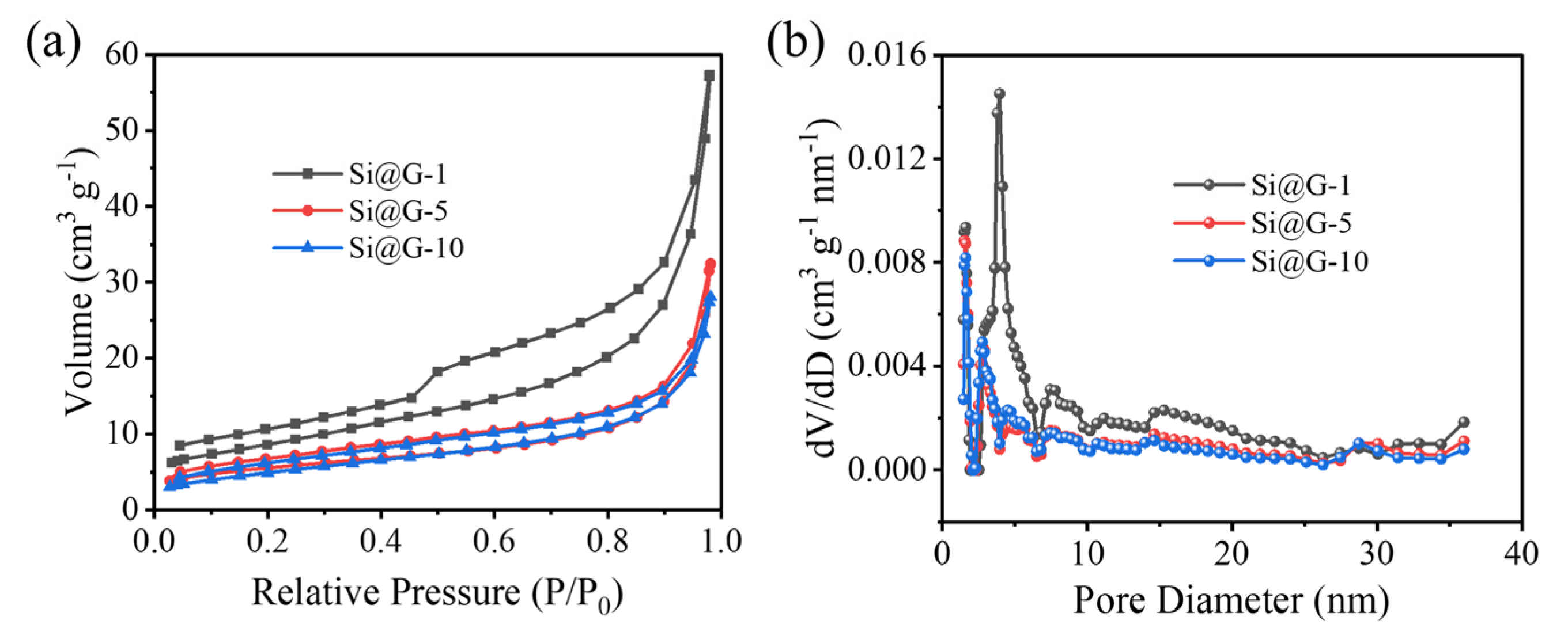
Figure 3a shows the nitrogen adsorption and desorption curves of Si@G-1, Si@G-5, and Si@G-10, and it is evident that the curves all show typical type IV isotherms. The climbing of the H3 hysteresis loop at a relative pressure (P/Po) of 0.8 to 1.0 is evidence of the presence of mesoporous structures, which may originate from the voids between the adjacent graphene. Apparently, the specific surface area of Si@G-1 is higher than that of Si@G-5 and Si@G-10 due to the relatively more disordered arrangement of graphene. The specific surface areas of Si@G-5 and Si@G-10 are comparable, and the less graphene content cannot change the silicon arrangement. In addition, the pore diameter distribution curves (Figure 3b) show that the pore diameter is mainly around 5 nm, which is favorable for the migration of Li+ to Si@G inside the composites [29].
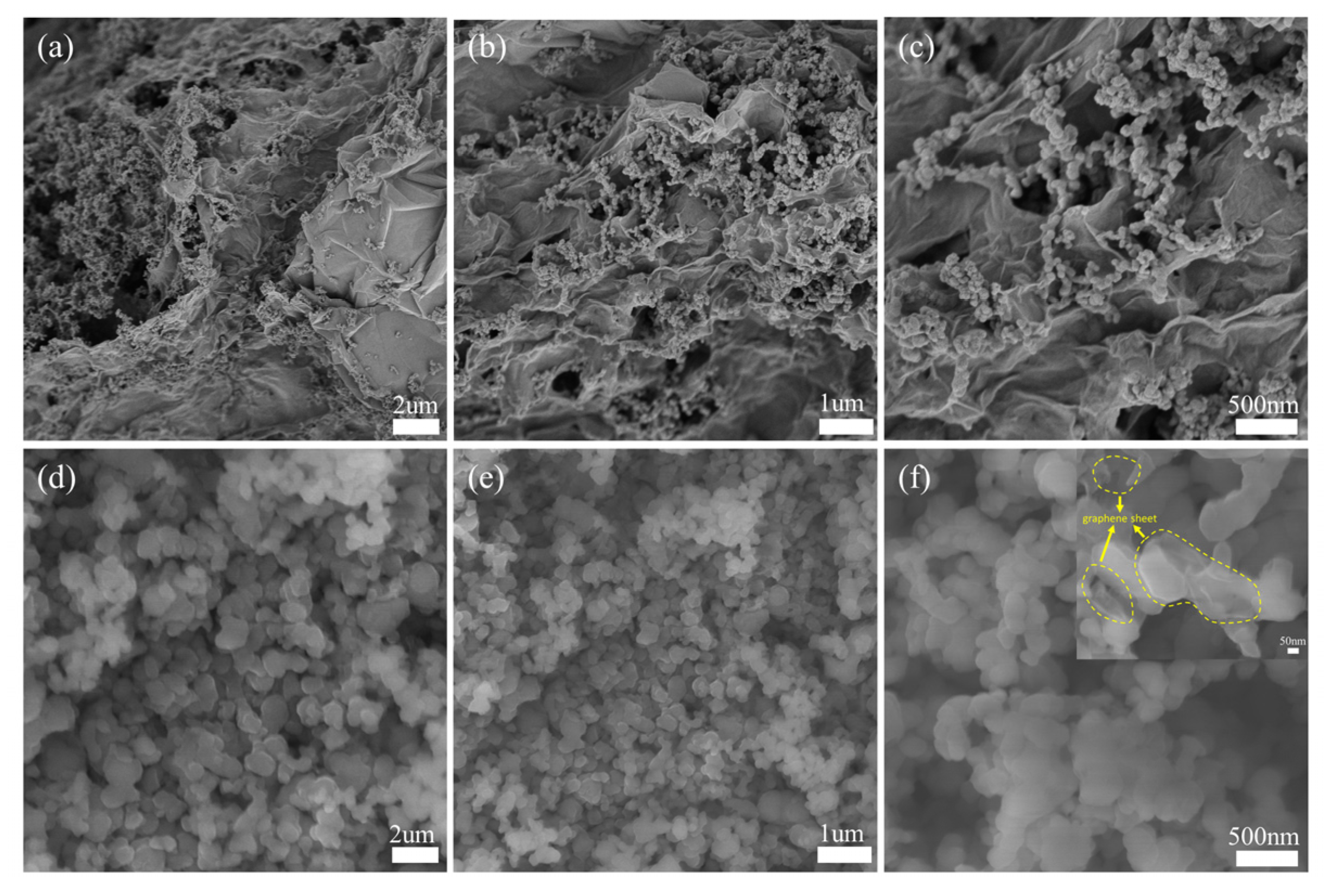
To characterize the morphology of the Si@G composites, SEM was performed. Figure 4a–c show the morphology of Si@G-1 sample. As can be observed, silicon nanoparticles (range of 50–100 nm) were anchored on graphene nanosheets, and the size of the graphene sheets was between 1 and 10 um. The silicon nanoparticles were completely encapsulated by the graphene nanosheets, and the agglomeration of silicon and the folding and stacking of graphene sheets created many voids that facilitated electrolyte penetration and Li+ transport [30,31]. At the same time, the silicon-loaded nanosheets were interconnected to provide additional electronic pathways. Figure 4d–f show the SEM images of the Si@G-5 composites, where more silicon nanoparticles mask the presence of graphene, but the graphene sheets can still be observed by higher magnification, as shown in Figure 4f. For the Si@G-10 sample, the extremely high content of silicon makes graphene not observable in the SEM images.
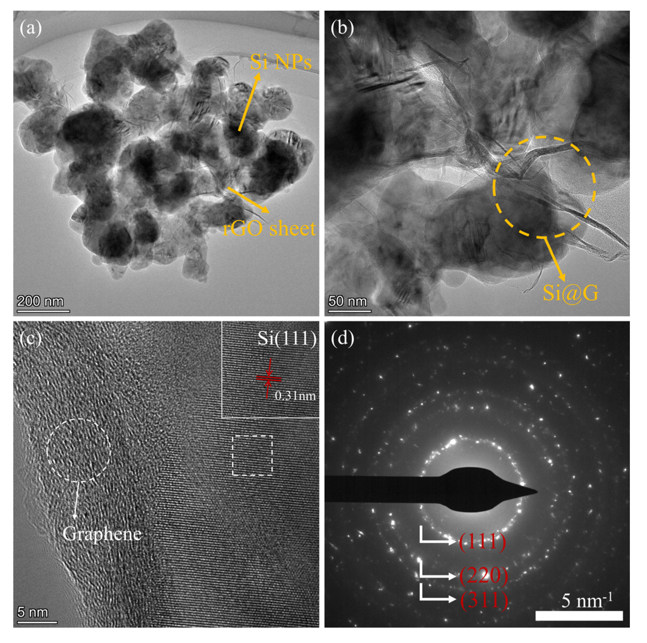
TEM was applied to further examine the structure of the Si@G-5 material. TEM images (Figure 5a,b) clearly demonstrate the presence of graphene sheets and silicon nanoparticles, with a few layers of large diameter graphene completely wrapping the silicon nanoparticles. It is evident that silicon nanoparticles are firmly anchored on graphene sheets due to the electrostatic binding effect. Figure 5c shows the HRTEM image of the silicon–graphene composite. The spacing of (111) is 0.31 nm, and a sheet of graphene tightly attached to the Si shells and amorphous carbon deposited on the surface of the composite can also be observed from the HRTEM image. From the dark-field diffraction image (Figure 5d), it is possible to derive each crystallographic plane of the Si nanoparticles, which confirms that the crystallinity of the Si nanoparticles is mostly preserved.

2.2. Electrochemical Studies

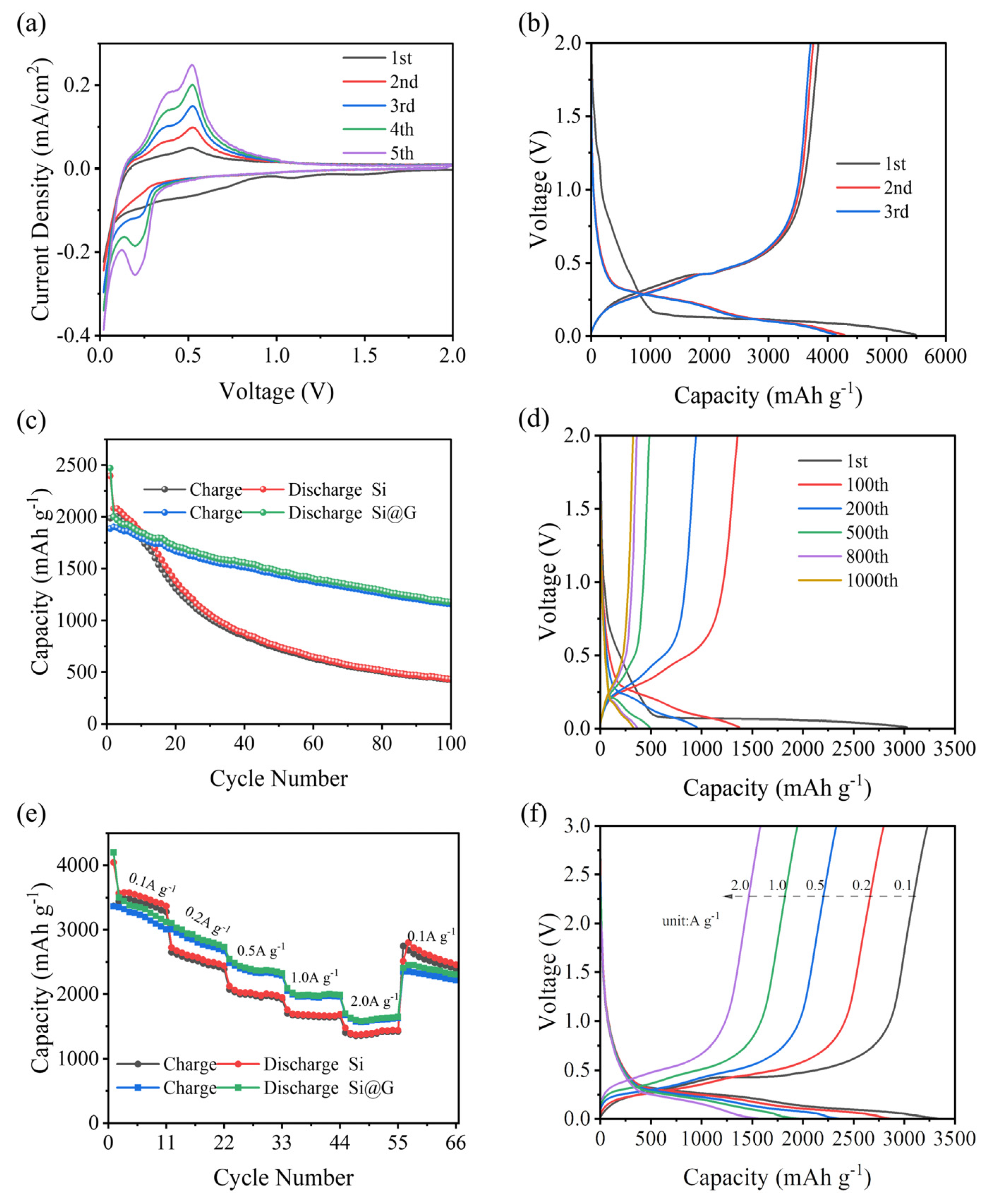
Structure and morphology analysis indicated that the Si@G-5 composite exhibited high crystallinity, proper specific surface area, and better integration. Thus, it was chosen to be tested as an electrode for the lithium half-cell, lithium-ion full cell, and dual-ion full battery. The half-cell was firstly assembled to evaluate the lithium storage capacity of the Si@G composite electrode using Si@G as the working electrode and lithium metal as the reference electrode. The CV curves of Si@G-5 are displayed in Figure 6a. Two cathodic peaks appeared in the first cycle. The broad peak at 0.69 V was attributed to the formation of the solid electrolyte interphase (SEI) and the contribution of graphene sheets [32,33]. Another cathodic peak out near 0.23 V was attributed to the transformation of the silicon structure from crystalline to amorphous [34]. In contrast, the two anodic peaks at 0.39 and 0.52 V corresponded to the de-lithiation process of amorphous LixSi to Si.
Figure 6b shows the first three GCD curves of Si@G-5 anode at 0.1 A g−1. Due to the formation of SEI films, the ICE is 69.94%. In the second and third cycles, the curves overlap almost completely, and the specific discharge capacity is about 4100 mAh g−1. This is consistent with the CV results, indicating that the Si@G-5 has excellent reversibility. Figure 6c shows the curve of the 100 cycles of nano-silicon and Si@G-5 with the same current density. Apparently, the Si@G-5 material had a specific capacity of 1182.40 mAh g−1 after 100 cycles, with a capacity retention of 59.12%, much higher than the pure silicon sample of 435.8 mAh g−1 and 20.94%. Figure 6d shows the GCD curves under different cycle numbers. Except for the low CE of the first cycle, the subsequent CEs are higher than 95%, indicating that Si@G-5 has excellent stability and electrochemical reversibility. This is due to the strong binding force produced by electrostatic action, which makes the volume expansion of Si@G-5 in the cycle process is significantly inhibited [35].
The rate performance of pure silicon and Si@G-5 were tested, as shown in Figure 6e. At 0.1, 0.2, 0.5, 1.0, and 2.0 A g−1, the discharge capacities were 3348.8/3520.3, 2567.1/2874.4, 1999.5/2369.4, 1672.1/1973.4, and 1390/1600 mAh g−1, respectively. Evidently, Si@G-5 performed better than pure silicon samples at each current density. When the current density was restored to 0.1 A g−1 again, the Si@G-5 specific capacity was restored to 2801.6 mAh g−1, the capacity retention was 83.66%, and the pure silicon sample was only 60.09%. Figure 6f shows the charge–discharge curves of Si@G-5 under different current densities. As the current density increased, the specific capacity decreased. However, the voltage difference between charging and discharging platforms was still small, which indicated that Si@G-5 had small polarization, high reversibility, and electrode stability. These excellent properties could be attributed to the introduction of graphene to enhance the charge transfer ability, and the graphene sheets could effectively inhibit the internal stress caused by the silicon volume expansion.
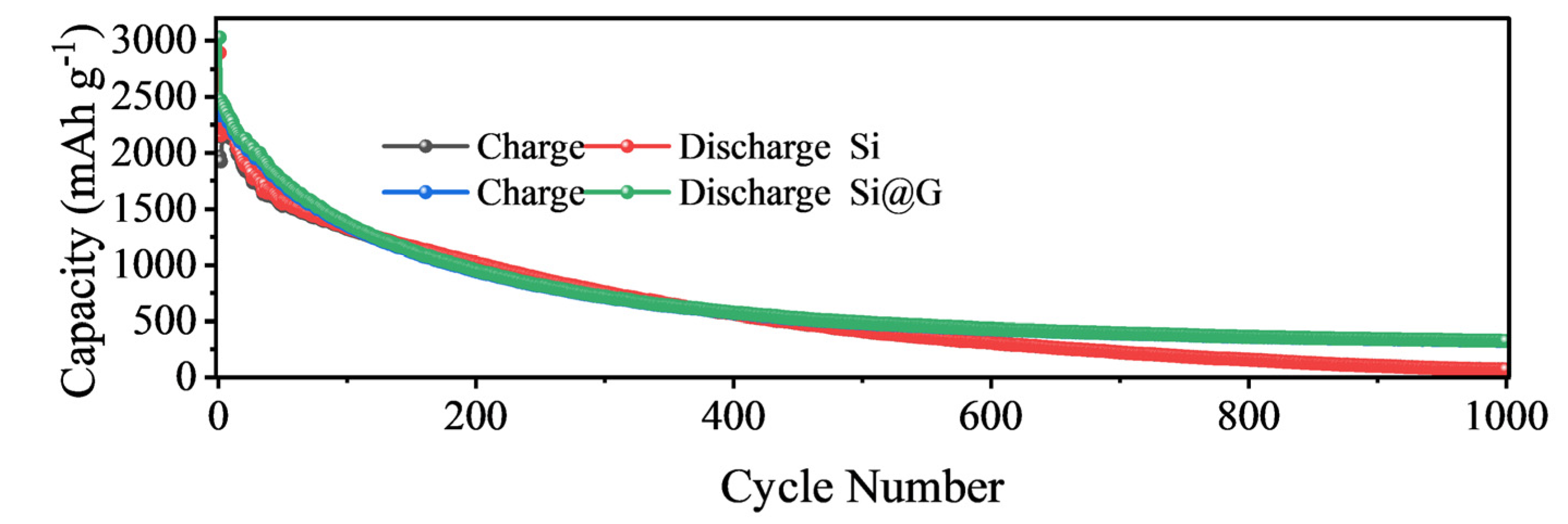
In addition to the excellent rate performance, the Si@G-5 electrode also demonstrated excellent long-term cycling stability. As shown in Figure 7, after 1000 cycles at 1.0 A g−1, the reversible specific capacity remained at 325.1 mAh g−1, while the pure silicon sample failed after 1000 cycles due to volume expansion [36].
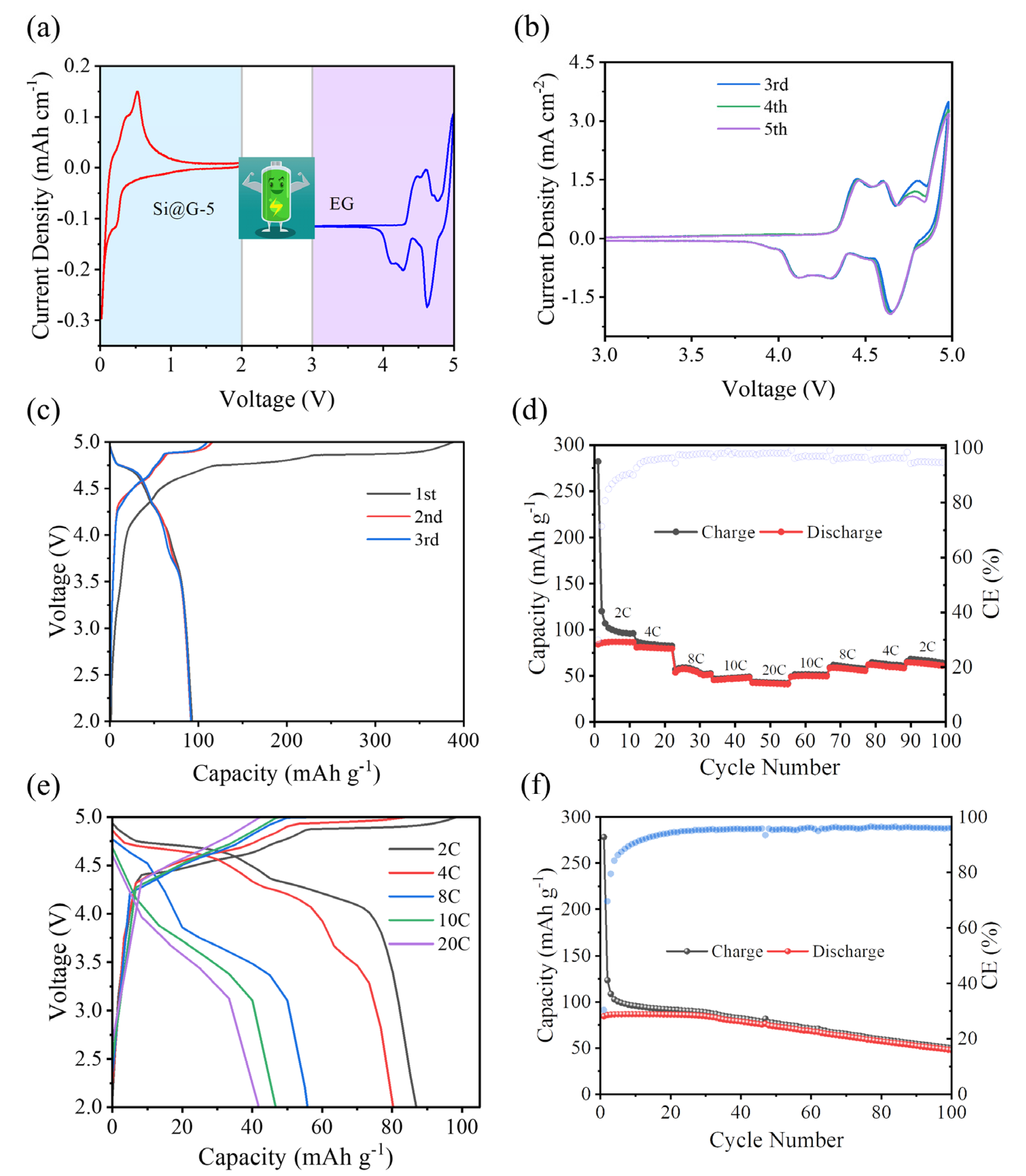
To verify the performance of the Si@G-5 in the DIB, the full cell of a lithium-based DIB was assembled, with Si@G-5 as the anode and (expanded graphite) EG as the cathode (Figure 8a). EG was selected because it possessed an enhanced interlaying distance, which could accommodate more PF6 intercalation. The detailed structure and electrochemical PF6 storage performances of the EG are shown in Figures S1–S3. Figure 8b shows the CV curves of the EG//Si@G-5 DIB, which almost entirely overlap, indicating the excellent electrochemical reversibility. Three evident oxidation peaks appeared around 4.29, 4.60, and 4.83 V, which were the initial electrochemical processes occurring jointly at the cathode and anode, corresponding to different intercalation processes of PF6 [37]. The first three cycles of the GCD curve of the EG//Si@G-5 DIB at 1 C are shown in Figure 8c, and the first charging specific capacity was up to 388.23 mAh g−1. However, the initial coulomb efficiency (ICE) was 24.31%, due to the formation of SEI films and side reactions [38]. Thereafter, the curves converge in terms of specific capacity and CE. The rate performance of the full cell is shown in Figure 8d. After 10 cycles at 2, 4, 6, 8, 10, 20, and 2 C in sequence, the discharge specific capacity recovered to 64.66 mAh g−1, with a capacity retention of 74.39%, and all CEs were around 95%. Figure 8e shows the GCD curves at different current densities. The cells have evident and similar charging and discharging plateaus, which correspond to the results of the CV curves. The capacity was 48.35 mAh g−1 after 100 cycles at 2 C, with a capacity retention of 57.18% (Figure 8f), and the capacity fade was also relatively slow. These were attributed to the synergistic effect of the cathode and anode, emphasizing the improved structure of the silicon-based electrode in the DIBs.
In addition, we also assembled a LiFePO4//Si@G-5 LIB full cell to compare the electrochemical performance of the LIB and DIB. The GCD curves and cycling curves of LiFePO4//Si@G-5 LIB are shown in Figures S4 and S5, respectively. The results show that its electrochemical performance was much less than EG//Si@G-5 DIB.
To further study the kinetic properties of the EG//Si@G-5 DIB, EIS was performed. Figure 9a shows the EIS plots of the EG//Si@G-5 DIB in the uncycled state, after 50 cycles, and after 200 cycles. The charge transfer resistance (Rct) was 34.03 Ω when uncycled (Figure 9b). After cycling, there was a different degree of increase in Rct (Figure 9c). This may have been due to the creation of SEI films in the first cycle and was also responsible for the irreversible capacity and cell performance degradation in the first cycle [39]. In the low-frequency region, the curve flattened out, owing to the decreasing rate of diffusion. However, a high ion migration rate could be maintained after 200 cycles. The fitted curves were calculated as σ0 = 170.51, σ50 = 669.40, and σ200 = 1328.49, resulting in Li+ diffusion coefficients of 1.37 × 10⁻²¹, 8.90 × 10⁻²³, and 2.26 × 10⁻²³ cm2 s−1 for the three, respectively (please refer to Equation (S1) for the detailed calculation procedure).
To evaluate the value of the EG//Si@G-5 DIB for practical applications, we calculated the energy density and power density at different current densities (Tables S1 and S2 and Equation (S2)). The EG//Si@G-5 DIB achieved an energy density of 367.84 Wh kg−1 at 2 C, while the LiFePO4//Si@G-5 LIB showed only a low energy density of 93.58 Wh kg−1. Moreover, the EG//Si@G-5 DIB could maintain a high energy density of 138.37 Wh kg−1 even at 20 C. These results demonstrated that the EG//Si@G-5 DIB held great potential for a high-performance energy storage device.

3. Materials and Methods

3.1. Chemicals and Reagents

For the synthesis of Si@G and EG materials, the following reagents were used: silicon powder (Si, cell grade), purchased from Shenzhen Huaqing Material Technology Co. (Shenzhen, China); natural graphite (C, purity ≥ 99%), purchased from Shenzhen Kejing Technology Co. (Shenzhen, China); Poly dimethyl diallyl ammonium chloride ((C8H16ClN)n, AR), sodium nitrate (NaNO3, AR), concentrated sulfuric acid (H2SO4, AR), potassium permanganate (KMnO4, AR), hydrogen peroxide (H2O2, AR), and anhydrous ethanol (C2H6O, AR), all the above chemical reagents were purchased from Sinopharm Chemical Reagent Co. (Shanghai, China). All chemical reagents used in this work were not further purified.

3.2. Material Preparation

3.2.1. Preparation of Si@G Anode Material

First, 100 mg Si powder was weighed and fully stirred in 50 mL deionized water for 30 min, and then 2 mL 20 wt% PDDA solution (Poly dimethyl diallyl ammonium chloride) was added. The solution was stirred and ultrasonically dispersed for 1 h. Then, the above solution was centrifuged at 10,000 rpm for 5 min, and the excess PDDA was removed three times to obtain a positively charged Si precipitate. In total, 100 mg of graphite oxide (GO) was weighed, 100 mL of deionized water was added, mixed, stirred, and sonicated for 1 h to obtain the GO solution (1.0 mg mL−1).
The prepared aqueous Si-PDDA solution was slowly added to the GO solution and stirred for 12 h. The solution was filtered to obtain Si@GO filter cake, which was then dried under vacuum at 80 °C for 12 h. The dried filter cake was ground into powder and then calcined at 900 °C under 10% H2/Ar atmosphere for 2 h. Finally, the Si@G-1 sample (for comparison, the addition of 500 mg and 1000 mg of silicon powder were noted as Si@G-5 and Si@G-10) was obtained. As illustrated in Figure 1, the fabrication process is clearly shown.

3.2.2. Preparation of EG Cathode Material

In total, 1 g of natural graphite and 0.5 g of NaNO3 were weighed and slowly added to 23 mL of concentrated H2SO4, while the temperature was controlled to below 5 °C. After stirring in a water bath for 30 min, the temperature was increased to 35 °C, and then 0.5 g of KMnO4 of different masses was added and kept stirred for 2 h. After that, 46 mL of deionized water was added, heated to 98 °C, and stirred continuously for 30 min. In total, 130 mL of deionized water and 10 mL of H2O2 were added.
The above solution was added to anhydrous ethanol and deionized water and continuously filtered at least four times to make the pH neutral. The filter cake was transferred to a vacuum oven and dried at 80 °C for 12 h. Subsequently, it was heated to 600 °C in N2 atmosphere and held for 5 h. Finally, EG was obtained.

3.3. Material Characterization

The crystal structure and composition were determined by X-ray diffraction (XRD, Ultima IV, using Cu Kα) at a scan rate of 10° min−1. The morphology was characterized by scanning electron microscopy (SEM, Hitachi SU8000, Hitachi, Tokyo, Japan). The microstructure was characterized by transmission electron microscopy (TEM, JEOL-2100F Plus, JEOL, Osaka, Japan). Raman spectroscopy was performed on a Raman spectrometer system (JY HR-800 Lab Ram), with a laser wavelength of 532 nm. The specific surface area, pore volume, and pore size distribution of the materials were tested by a specific surface area and porosity analyzer (BET, Micromeritics ASAP 2460, Norcross, GA, USA), with nitrogen adsorption and desorption tests at 77.3 K.

3.4. Electrochemical Characterization

The Si@G or EG, binder carboxymethyl cellulose (CMC), and conductive agent Super P were weighed in the ratio of 7:2:1, mixed and ground, and then anhydrous ethanol and deionized water was added in a 1:1 solution as a solvent and stirred for 12 h. After that, the resulting slurry was daubed on the aluminum foil, dried under vacuum at 80 °C for 12 h, and cut into 14 mm diameter round pole pieces after drying.
The CR2032 button cell was made in an argon-filled glove box. Half-cell was assembled to evaluate the lithium storage capacity of Si@G composite. Si@G was used as working electrodes. Lithium metal was used as both counter and reference electrode. Celgard-2400 was used as the separator. In total, 1 M LiPF6 and 10 wt% fluoroethylene carbonate (FEC) in a 1:1:1 (volume ratio) mixture of ethylene carbonate (EC), diethyl carbonate (DEC), and dimethyl carbonate (DMC) was used as the electrolyte. In full-DIB assembly, EG was used as the cathode, Si@G was used as anode, and the electrolyte was changed to 4 M LiPF6 and 2.0% VC in the ethyl methyl carbonate (EMC). The higher lithium salt concentration induced the solvent molecules to complex with LiPF6. At high voltage, the complexed solvent molecules had stronger antioxidant properties, and the electrolyte was more stable. In addition, the VC in the electrolyte as an additive could preferentially form a SEI film with excellent performance on the graphite electrode, which could effectively inhibit the continuous decomposition of solvent molecules on the electrode surface. Cyclic voltammetry (CV) was performed on ModuLab XM ECS-type electrochemical workstation at scan rates of 0.5 mV s−1 between 3.00–5.00 V. Charge/discharge tests (GCD) at different current densities at 3.00–5.00 V were performed with the NEWARE 8.0 battery test system. Electrochemical impedance spectroscopy (EIS) was performed on a ModuLab XM ECS-type electrochemical workstation, with a frequency of 0.01 Hz–100 kHz and an amplitude of 5 mV.

4. Conclusions

In summary, we prepared a silicon and graphene composite (Si@G) anode through in-situ electrostatic self-assembly and a post-annealing reduction process and investigated it as an anode in full DIBs, together with home-made expanded graphite (EG) as a fast kinetic cathode. The composite structure could suppress the stress/strain induced by volume change and alleviated the pulverization during charging and discharging. In addition, the graphene layer adhered on the surface of Si nanospheres could weaken volume expansion, prevent the inter-agglomeration of Si, and improve the conductivity. Benefiting from that, the as-prepared Si@G anode could retain a maximum specific capacity of 1182.4 mAh g−1 after 100 cycles, while the bare Si anode only maintained at 435.8 mAh g−1. Moreover, the full Si@G //EG DIBs achieved a high energy density of 367.84 Wh kg−1 at a power density of 855.43 W kg−1. Thus, this work shed some light on the practical applications of high energy DIBs.

Supplementary Materials

The following supporting information can be downloaded at: https://www.mdpi.com/article/10.3390/molecules28114280/s1, Figure S1: XRD and Raman plot of graphite and EG; Figure S2: GCD curves and rate diagrams for graphite and EG; Figure S3: GCD curves at different current densities; Figure S4: GCD curves of LiFePO4//Si@G-5 LIB at different current densities; Figure S5: Cycle curve of LiFePO4//Si@G-5 LIB; Table S1: Energy density and power density of EG//Si@G-5 DIB at different current densities; Table S2: Energy density and power density of LiFePO4//Si@G-5 LIB at different current densities.

Author Contributions

Conceptualization, Q.S., G.L. and X.L.; methodology, G.L. and X.L.; software, X.M.; validation, X.T.; formal analysis, X.Z. (Xiaobin Zhang); investigation, J.D. and Y.M.; writing—original draft preparation, Q.S.; writing—review and editing, X.L.; supervision, N.C. and Q.S.; project administration, Q.S.; funding acquisition, X.Z. (Xiaobei Zang). All authors have read and agreed to the published version of the manuscript.

Funding

This work was supported by the Natural Science Foundation of Shandong Province with grant (ZR2020QE048) and the National Natural Science Foundation of China with grant (21905304).

Institutional Review Board Statement

The study did not require ethical approval.

Informed Consent Statement

Not applicable.

Data Availability Statement

Data will be made available on request.

Conflicts of Interest

The authors declare that they have no conflict of interest.

Sample Availability

Samples are available from the authors upon request.

References

  1. Hadjipaschalis, I.; Poullikkas, A.; Efthimiou, V. Overview of current and future energy storage technologies for electric power applications. Renew. Sustain. Energy Rev. 2009, 13, 1513–1522. [Google Scholar] [CrossRef]
  2. Naik, M.V. Recent advancements and key challenges with energy storage technologies for electric vehicles. Int. J. Electr. Hybrid Veh. 2021, 13, 256–288. [Google Scholar] [CrossRef]
  3. Niu, J.; Zhang, S.; Niu, Y.; Song, H.; Chen, X.; Zhou, J. Silicon-Based Anode Materials for Lithium-Ion Batteries. Prog. Chem. 2015, 27, 1275–1290. [Google Scholar]
  4. Ji, B.; Zhang, F.; Song, X.; Tang, Y. A Novel Potassium-Ion-Based Dual-Ion Battery. Adv. Mater. 2017, 29, 1700519. [Google Scholar] [CrossRef]
  5. Wang, S.; Jiao, S.; Tian, D.; Chen, H.-S.; Jiao, H.; Tu, J.; Liu, Y.; Fang, D.-N. A Novel Ultrafast Rechargeable Multi-Ions Battery. Adv. Mater. 2017, 29, 1606349. [Google Scholar] [CrossRef]
  6. Sui, Y.; Liu, C.; Masse, R.C.; Neale, Z.G.; Atif, M.; AlSalhi, M.; Cao, G. Dual-ion batteries: The emerging alternative rechargeable batteries. Energy Storage Mater. 2020, 25, 1–32. [Google Scholar] [CrossRef]
  7. Wang, M.; Tang, Y. A Review on the Features and Progress of Dual-Ion Batteries. Adv. Energy Mater. 2018, 8, 1703320. [Google Scholar] [CrossRef]
  8. Zheng, C.; Wu, J.; Li, Y.; Liu, X.; Zeng, L.; Wei, M. High-Performance Lithium-Ion-Based Dual-Ion Batteries Enabled by Few-Layer MoSe2/Nitrogen-Doped Carbon. ACS Sustain. Chem. Eng. 2020, 8, 5514–5523. [Google Scholar] [CrossRef]
  9. Zhang, X.; Tang, Y.; Zhang, F.; Lee, C.-S. A Novel Aluminum–Graphite Dual-Ion Battery. Adv. Energy Mater. 2016, 6, 1502588. [Google Scholar] [CrossRef]
  10. Zhou, J.; Zhou, Y.; Zhang, X.; Cheng, L.; Qian, M.; Wei, W.; Wang, H. Germanium-based high-performance dual-ion batteries. Nanoscale 2020, 12, 79–84. [Google Scholar] [CrossRef]
  11. Luo, P.; Zheng, C.; He, J.; Tu, X.; Sun, W.; Pan, H.; Zhou, Y.; Rui, X.; Zhang, B.; Huang, K. Structural Engineering in Graphite-Based Metal-Ion Batteries. Adv. Funct. Mater. 2021, 32, 2107277. [Google Scholar] [CrossRef]
  12. Zhang, L.; Wang, H.; Zhang, X.; Tang, Y. A Review of Emerging Dual-Ion Batteries: Fundamentals and Recent Advances. Adv. Funct. Mater. 2021, 31, 2010958. [Google Scholar] [CrossRef]
  13. Ou, X.; Gong, D.; Han, C.; Liu, Z.; Tang, Y. Advances and Prospects of Dual-Ion Batteries. Adv. Energy Mater. 2021, 11, 2102498. [Google Scholar] [CrossRef]
  14. Han, Y.; Qi, P.; Feng, X.; Li, S.; Fu, X.; Li, H.; Chen, Y.; Zhou, J.; Li, X.; Wang, B. In Situ Growth of MOFs on the Surface of Si Nanoparticles for Highly Efficient Lithium Storage: Si@MOF Nanocomposites as Anode Materials for Lithium-Ion Batteries. ACS Appl. Mater. Interfaces 2015, 7, 2178–2182. [Google Scholar] [CrossRef] [PubMed]
  15. Zheng, P.; Sun, J.; Liu, H.; Wang, R.; Liu, C.; Zhao, Y.; Li, J.; Zheng, Y.; Rui, X. Microstructure Engineered Silicon Alloy Anodes for Lithium-Ion Batteries: Advances and Challenges. Batter. Supercaps 2023, 6, e202200481. [Google Scholar] [CrossRef]
  16. Raić, M.; Mikac, L.; Marić, I.; Štefanić, G.; Škrabić, M.; Gotić, M.; Ivanda, M. Nanostructured Silicon as Potential Anode Material for Li-Ion Batteries. Molecules 2020, 25, 891. [Google Scholar] [CrossRef]
  17. Shi, C.; Chen, J.; Guo, T.; Luo, G.; Shi, H.; Shi, Z.; Qin, G.; Zhang, L.; He, X. Controllable Preparation to Boost High Performance of Nanotubular SiO2@C as Anode Materials for Lithium-Ion Batteries. Batteries 2023, 9, 107. [Google Scholar] [CrossRef]
  18. Fang, H.; Liu, Q.; Feng, X.; Yan, J.; Wang, L.; He, L.; Zhang, L.; Wang, G. Carbon-Coated Si Nanoparticles Anchored on Three-Dimensional Carbon Nanotube Matrix for High-Energy Stable Lithium-Ion Batteries. Batteries 2023, 9, 118. [Google Scholar] [CrossRef]
  19. Duan, H.; Xu, H.; Wu, Q.; Zhu, L.; Zhang, Y.; Yin, B.; He, H. Silicon/Graphite/Amorphous Carbon as Anode Materials for Lithium Secondary Batteries. Molecules 2023, 28, 464. [Google Scholar] [CrossRef]
  20. Shi, F.; Song, Z.; Ross, P.N.; Somorjai, G.A.; Ritchie, R.O.; Komvopoulos, K. Failure mechanisms of single-crystal silicon electrodes in lithium-ion batteries. Nat. Commun. 2016, 7, 11886. [Google Scholar] [CrossRef]
  21. Jung, H.; Park, M.; Yoon, Y.-G.; Kim, G.-B.; Joo, S.-K. Amorphous silicon anode for lithium-ion rechargeable batteries. J. Power Sources 2003, 115, 346–351. [Google Scholar] [CrossRef]
  22. Du, F.-H.; Wang, K.-X.; Chen, J.-S. Strategies to succeed in improving the lithium-ion storage properties of silicon nanomaterials. J. Mater. Chem. A 2016, 4, 32–50. [Google Scholar] [CrossRef]
  23. Chae, S.; Ko, M.; Kim, K.; Ahn, K.; Cho, J. Confronting Issues of the Practical Implementation of Si Anode in High-Energy Lithium-Ion Batteries. Joule 2017, 1, 47–60. [Google Scholar] [CrossRef]
  24. He, S.; Wang, S.; Chen, H.; Hou, X.; Shao, Z. A new dual-ion hybrid energy storage system with energy density comparable to that of ternary lithium ion batteries. J. Mater. Chem. A 2020, 8, 2571–2580. [Google Scholar] [CrossRef]
  25. Li, C.; Ju, Y.; Yoshitake, H.; Yoshio, M.; Wang, H. Preparation of Si-graphite dual-ion batteries by tailoring the voltage window of pretreated Si-anodes. Mater. Today Energy 2018, 8, 174–181. [Google Scholar] [CrossRef]
  26. Jiang, C.; Xiang, L.; Miao, S.; Shi, L.; Xie, D.; Yan, J.; Zheng, Z.; Zhang, X.; Tang, Y. Flexible interface design for stress regulation of a silicon anode toward highly stable dual-ion batteries. Adv. Mater. 2020, 32, 1908470. [Google Scholar] [CrossRef]
  27. Feng, K.; Ahn, W.; Lui, G.; Park, H.W.; Kashkooli, A.G.; Jiang, G.; Wang, X.; Xiao, X.; Chen, Z. Implementing an in-situ carbon network in Si/reduced graphene oxide for high performance lithium-ion battery anodes. Nano Energy 2016, 19, 187–197. [Google Scholar] [CrossRef]
  28. Fatima, A.; Majid, A.; Haider, S.; Akhtar, M.S.; Alkhedher, M. First principles study of layered silicon carbide as anode in lithium ion battery. Int. J. Quantum Chem. 2022, 122, e26895. [Google Scholar] [CrossRef]
  29. Wang, C.; Zhang, C.; Xue, Q.; Li, C.; Miao, J.; Ren, P.; Yang, L.; Yang, Z. Atomic mechanism of the distribution and diffusion of lithium in a cracked Si anode. Scr. Mater. 2021, 197, 113807. [Google Scholar] [CrossRef]
  30. Han, C.; Si, H.; Sang, S.; Liu, K.; Liu, H.; Wu, Q. Achieving fully reversible conversion in Si anode for lithium-ion batteries by design of pomegranate-like Si@C structure. Electrochem. Acta 2021, 389, 138736. [Google Scholar] [CrossRef]
  31. Zhang, X.; Wang, D.; Qiu, X.; Ma, Y.; Kong, D.; Müllen, K.; Li, X.; Zhi, L. Stable high-capacity and high-rate silicon-based lithium battery anodes upon two-dimensional covalent encapsulation. Nat. Commun. 2020, 11, 3826. [Google Scholar] [CrossRef] [PubMed]
  32. Kim, W.-S.; Choi, J.; Hong, S.-H. Meso-porous silicon-coated carbon nanotube as an anode for lithium-ion battery. Nano Res. 2016, 9, 2174–2181. [Google Scholar] [CrossRef]
  33. Zheng, Z.; Wu, H.-H.; Chen, H.; Cheng, Y.; Zhang, Q.; Xie, Q.; Wang, L.; Zhang, K.; Wang, M.-S.; Peng, D.-L.; et al. Fabrication and understanding of Cu3Si-Si@ carbon@ graphene nanocomposites as high-performance anodes for lithium-ion batteries. Nanoscale 2018, 10, 22203–22214. [Google Scholar] [CrossRef] [PubMed]
  34. Ke, C.-Z.; Liu, F.; Zheng, Z.-M.; Zhang, H.-H.; Cai, M.-T.; Li, M.; Yan, Q.-Z.; Chen, H.-X.; Zhang, Q.-B. Boosting lithium storage performance of Si nanoparticles via thin carbon and nitrogen/phosphorus co-doped two-dimensional carbon sheet dual encapsulation. Rare Met. 2021, 40, 1347–1356. [Google Scholar] [CrossRef]
  35. Xu, Y.; Yin, G.; Ma, Y.; Zuo, P.; Cheng, X. Nanosized core/shell silicon@carbon anode material for lithium ion batteries with polyvinylidene fluoride as carbon source. J. Mater. Chem. 2010, 20, 3216–3220. [Google Scholar] [CrossRef]
  36. Wan, X.; Tang, Z.; Chen, J.; Xue, Y.; Zhang, J.; Guo, X.; Liu, Y.; Kong, Q.; Yuan, A.; Fan, H. Molten Salt-assisted Magnesiothermic Reduction Synthesis of Spherical Si Hollow Structure as Promising Anode Materials of Lithium Ion Batteries. Chem. Lett. 2019, 48, 1547–1550. [Google Scholar] [CrossRef]
  37. Matsuo, Y.; Sekito, K.; Ashida, Y.; Inamoto, J.; Tamura, N. Factors Affecting the Electrochemical Behaviors of Graphene-like Graphite as a Positive Electrode of a Dual-Ion Battery. ChemSusChem 2023, 16, e202201127. [Google Scholar] [CrossRef]
  38. Li, X.; Sun, X.; Hu, X.; Fan, F.; Cai, S.; Zheng, C.; Stucky, G.D. Review on comprehending and enhancing the initial Coulombic efficiency of anode materials in lithium-ion/sodium-ion batteries. Nano Energy 2020, 77, 105143. [Google Scholar] [CrossRef]
  39. Lei, H.; Wang, H.; Cheng, B.; Zhang, F.; Liu, X.; Wang, G.; Wang, B. Anion-Vacancy Modified WSSe Nanosheets on 3D Cross-Networked Porous Carbon Skeleton for Non-Aqueous Sodium-Based Dual-Ion Storage. Small 2023, 19, e2206340. [Google Scholar] [CrossRef]
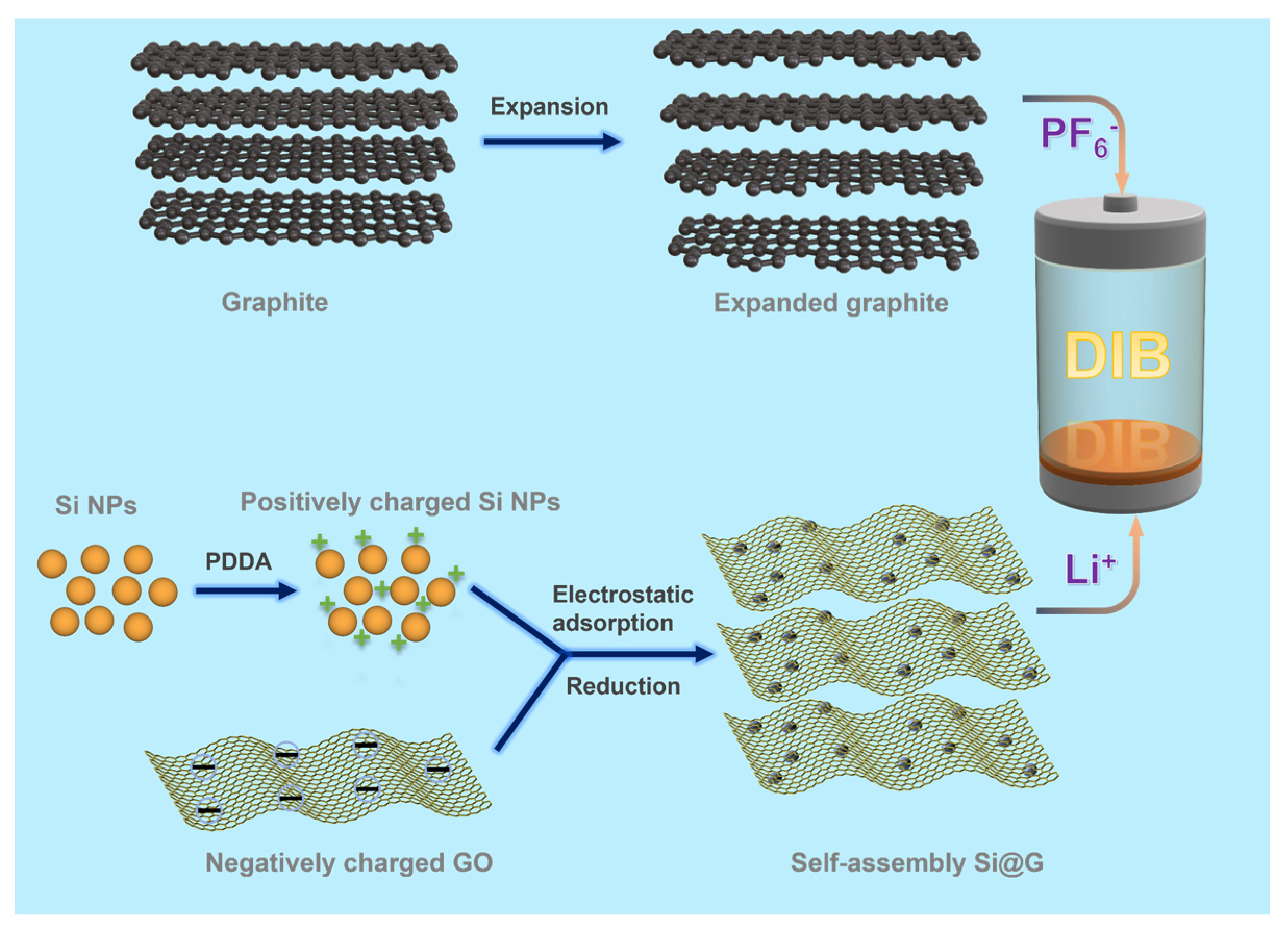
Figure 1. Diagram of the preparation process.
Molecules 28 04280 g001
Figure 2. (a) XRD comparison of Si@G-1, Si@G-5, and Si@G-10, (b) XRD of Si@G-5 and GO, (c) Raman plot comparison of Si@G-1, Si@G-5, and Si@G-10.
Molecules 28 04280 g002
Figure 3. (a) Comparison of BET nitrogen adsorption and desorption curves for Si@G-1, Si@G-5, and Si@G-10 samples, (b) pore diameter distribution.
Molecules 28 04280 g003
Figure 4. SEM comparison at different magnifications: (ac) Si@G-1, (df) Si@G-5.
Molecules 28 04280 g004
Figure 5. (a,b) TEM images of Si@G-5 material at different magnifications, (c) HRTEM of silicon–graphene composites, (d) Dark-field diffraction images of Si@G-5.
Molecules 28 04280 g005
Figure 6. (a) CV curves of the first five cycles of the Si@G-5 electrode at 0.5 mV s−1, (b) Charge-discharge curves of the first three cycles of the Si@G-5 electrode at 0.1 A g−1, (c) GCD comparisons between pure silicon and Si@G-5 at 0.2 A g−1, (d) GCD curves of Si@G-5 at 1 A g−1 for different cycles, (e) Comparison of rate performance between pure silicon and Si@G-5, (f) Charge–discharge curves of Si@G-5 at different current densities.
Molecules 28 04280 g006
Figure 7. Comparison of long-term cycle performance of pure Si and Si@G-5 at 1.0 A g−1.
Molecules 28 04280 g007
Figure 8. Electrochemical performance of EG//Si@G-5 DIB: (a) selection of voltage range, (b) CV curves at 0.5 mV s−1, (c) the first three GCD curves at 1 C, (d) rate performance, (e) GCD curves at different current densities, (f) 100 cycles performance at 2 C.
Molecules 28 04280 g008
Figure 9. EG//Si@G-5 DIB kinetic analysis: (a) EIS comparison at different cycle times, (b) EIS without cycle, (c) EIS comparison after 50 and 200 cycles (The inset is the equivalent circuit diagram).
Molecules 28 04280 g009
Disclaimer/Publisher’s Note: The statements, opinions and data contained in all publications are solely those of the individual author(s) and contributor(s) and not of MDPI and/or the editor(s). MDPI and/or the editor(s) disclaim responsibility for any injury to people or property resulting from any ideas, methods, instructions or products referred to in the content.