Article

DFT Investigations of Aun Nano-Clusters Supported on TiO2 Nanotubes: Structures and Electronic Properties

College of Chemistry, Sichuan University, Chengdu 610064, China
*
Author to whom correspondence should be addressed.
Molecules 2022, 27(9), 2756; https://doi.org/10.3390/molecules27092756
Submission received: 22 March 2022 / Revised: 17 April 2022 / Accepted: 21 April 2022 / Published: 25 April 2022
(This article belongs to the Section Computational and Theoretical Chemistry)

Abstract

:
TiO2 nanotubes (TiO2NTs) are beneficial for photogenerated electron separation in photocatalysis. In order to improve the utilization rate of TiO2NTs in the visible light region, an effective method is to use Aun cluster deposition-modified TiO2NTs. It is of great significance to investigate the mechanism of Aun clusters supported on TiO2NTs to strengthen its visible-light response. In this work, the structures, electronic properties, Mulliken atomic charge, density of states, band structure, and deformation density of Aun (n = 1, 8, 13) clusters supported on TiO2NTs were investigated by DMOL3. Based on published research results, the most stable adsorption configurations of Aun (n = 1, 8, 13) clusters supported with TiO2NTs were obtained. The adsorption energy increased as the number of Au adatoms increased linearly. The Aun clusters supported on TiO2NTs carry a negative charge. The band gaps of the three most stable structures of each adsorption system decreased compared to TiO2NTs; the valence top and the conduction bottom of the Fermi level come mainly from the contribution of 5d and 6s-Au. The electronic properties of the 5d and 6s impurity orbitals cause valence widening and band gap narrowing.

1. Introduction

The research on nanostructure models of metal clusters supported on well-ordered metal oxide surfaces is significant, providing important insights into the properties and mechanisms of real catalyst systems, and thus has been conducted extensively over the past few years [1,2,3,4,5,6,7,8,9,10,11,12,13]. In these model systems, the nature and strength of the interaction between the metal clusters and the support materials not only govern the nucleation and stability of the metal clusters, but also control the geometric and electronic structure of the resulting cluster/oxide interface, which are in turn critical to the catalytic activity of oxide-supported metal clusters [1,2]. Titanium dioxide has attracted worldwide attention due to its potential applications in a wide variety of products, such as photocatalysis [14,15], solar cells [16,17,18], and designing nanostructure architectures [19,20,21,22,23], due to its excellent gas sensitivity, moisture sensitivity, dielectric effect, photoelectric conversion and photocatalytic properties, chemical stability, nontoxicity, and relatively low cost. Among the three different polymorphs of TiO2, rutile, anatase, and brookite, the anatase phase has been extensively studied over the last few decades due to its technological applications and photocatalysis [24]. However, the low surface area (ca. 50 m2/g) and the large band gap of TiO2 (about 3.2 eV in the anatase phase [25]) limit its light absorption to only 5% of the solar spectrum [26,27,28], restricting its applications. In order to make more use of solar energy to increase the photocatalytic efficiency, it is more beneficial for absorbing visible light to reduce the band gap of TiO2 and increase the surface area of TiO2 materials. As is well known to us, among the nanostructures, namely simple assemblies of nanoparticles, one-dimensional (1D) nanostructures (nanorods, nanowires, and nanotubes) have a relatively large surface area. Accordingly, the TiO2 nanotubes (TiO2NTs) constructed by anatase are a promising structure with a large surface area of 328 m2/g [29]. Furthermore, TiO2NTs have a smaller band gap than the bulk powders and strong adsorption capacity, which will be desired to improve the photocatalytic properties and photoelectricity conversion effects, and have attracted considerable attention. A 3D random network of nanoparticles with more particle boundaries is more beneficial for transporting charge carriers than 1D nanostructures. Therefore, the collection of photogenerated charge carriers should be enhanced for adopted 1D nanostructure materials [30,31,32,33].
Although the smaller band gap of TiO2NTs was beneficial in the absorbing of visible lights [34], they clearly required more solar energy than modified nanotubes. In order to enhance the visible light sensitivity of TiO2 photocatalyst materials, many efforts have been made. The main modification methods are the organic dye photosensitive process, noble metal deposition, metal ion doping, the semiconductor coupling method, and so on. Metal nanoparticles (NPs) have considerably better photostability than semiconductor quantum dots, which usually suffer from anodic corrosion [26,35,36]. Some metal elements such as Au, Pt, Ag, Cu, and Fe have been employed to tune the electronic structure and enhance the catalytic activity of TiO2NTs [4,37,38,39,40,41,42,43,44]. Among various metal clusters, the Au cluster is considered as one of the most promising candidates owing to its high conductivity, good stability in the air, and controllability of the electrical properties. In contrast to the noble character of bulk Au, the Au cluster/metal oxide system (such as Au/TiO2) has been extensively studied due to the unique catalytic activity of this system. Recently, Zhi and co-workers [37] demonstrated that an Au nanoparticle–TiO2 nanotube junction was formed by using bovine serum albumin as a biotemplate, with the Au nanoparticles formed in the tube channels and even in the space between the tube bottom and the Ti substrate, which show highly improved electrochemical conductivity and act as electrode materials to achieve the enhanced direct electrochemistry of heme proteins. Shao et al. [38] reported plasmonic Au particles loaded on anodic TiO2 nanotube films exhibiting about 145% enhancement of the photocurrent and 37% reduction in response time. Chen et al. [39] synthesized the TiO2 nanotube-supported Pt/Au nanoparticles by means of the photo-assisted deposition approach. The studies have shown that TiO2NT-supported Pt/Au nanoparticles exhibit very high electrocatalytic activity toward formic acid oxidation when the Au composition is between 30% and 50%. Zhao et al. [4] prepared Au (or Pt) loaded on TiO2 nanotubes by means of the photo-deposition method for the degradation of methyl orange. The Au-loaded sample with an adsorption peak in the visible range becomes a visible light photocatalyst. In addition, other researchers [40,41,42,43,44] combined Au nanoparticles with other metal-loaded TiO2NTs to achieve high catalytic performance.
For Au nanoparticles supported on TiO2 nanotube systems, numerous investigations have been performed through many experiments. By contrast, the theoretical research providing important insights into the properties and mechanisms of real catalyst systems is scarce and significant. The purpose of this work is to investigation the micromechanisms of energy and charge transport in the nano-junction consisting of TiO2NTs and Aun clusters by building a nanostructure catalyst model. In this work, we report our results of first principles DFT calculation of Aun clusters supported on the anatase TiO2NT surface. The TiO2NTs were obtained by rolling up a TiO2 (101) surface, which was prepared by cleaving anatase bulk TiO2 perpendicular to the [1 0 1] direction. The anatase (101) surface was selected due to its thermodynamic stability [45,46,47,48]. In adsorption experiments, we adopted a single Au atom to test the adsorption sites of the TiO2NT surface. For the catalytic performance of Au, nanoparticles were defined by three major factors: contact structure, support selection, and particle size [49]. The 3D conformations are better suited for adsorption on a surface and concomitant oxidation and reduction reactions compared with planar conformations [7,50]. The measurements of CO oxidation using the temperature-programmed reaction by A. Sanchez [51] showed that the smallest gold cluster that catalyzes the reaction is Au8. Similar results were obtained by Hannu Häkkinen [52] and Bokwon Yoon [53]. Based on previous research [49,50,51,52,53,54], the adsorptive conformation of Au8 biplanar was adopted in our study. Atomic clusters show both electronic and geometric magic numbers, and 13 is a common magic number for many transition-metal clusters, including Au [55,56]. For Aun nanoclusters with 11 to 14 atoms, there appears to be a transition from 2D to 3D structures [57]. The work of J. Oviedo suggested that the most stable structure of Au13 comprises face-centered cubes or icosahedrons [55]. Ghazal Shafai et al. [57] selected the lowest-energy isomers for four types of cluster: planar, flake, cuboctahedron, and icosahedrons. The results show that there is no energy barrier between the icosahedron and the cuboctahedron configurations. Under the principle of three-dimensional configuration, we adopted a face-centered cubic and icosahedron structure for the original structures of the Au13 cluster. After optimization, the icosahedrons deformed into a distorted face-centered cubic structure, which is consistent with results of [57]. Therefore, we used a cuboctahedron as the initial configuration of the Au13 cluster. After the geometric optimization without symmetry being restricted, an energy-stable Au13 cuboctahedral structure was obtained. In order to understand the driving mechanism that determines the morphology and charge transport of TiO2NT-supported Aun nanoparticles, the structural and electronic properties of the adsorption systems were studied.

2. Methodology

The geometric structures of the bare nanotube and bare Aun clusters are shown in Figure 1. All the calculations were performed using the semi-core pseudopotential method within the DFT framework. Exchange and correlation terms were considered within the generalized gradient approximation (GGA) with a Perdew–Burke–Ernzerof (PBE) functional [58], the all-electron double numerical basis set with a polarized function (DNP), as implemented in Dmol3 code [59,60]. A tetragonal supercell with the size of 40 Å × 40 Å × c Å was set, where the parameter c was 11 Å, equal to the minimum periodic unit length of the TiO2NT (6,0). The supercell included 32 titanium and 64 oxygen atoms with the crystal form of (TiO2)32. The Brillouin zone was sampled by 4*4*2 [61] special k-points using the Monkhorst Pack [62] scheme for geometrical optimizations and the electronic properties calculation of TiO2 anatase, TiO2NT, and adsorption systems, respectively. A spin-restricted formalism was employed even in the presence of unpaired electrons, as the geometrical optimization is extremely sensitive to the details of the computational approach. The calculated bulk anatase TiO2 lattice parameters (a = b = 3.8283 Å, c = 9.5734 Å, u = 0.2080 Å, where u = dap/c is the internal coordinate and dap is the Ti-O top bond length) agree well with the experiments [25,63]. The calculated band gap of pure anatase TiO2 is 2.77 eV, which is smaller than the experimental value, 3.2 eV [25]. This is due to the fact that density functional theory does not consider the electronic exchange-correlation potential discontinuity, which results in the basic band gap width being smaller than the experimental value by about 30–50%, generally. This does not affect the analysis of the electronic structure. The initial single-walled anatase TiO2NT models were constructed by rolling up one (101) layer of the anatase structure in the 1 ¯ 01 direction [30,34,64,65]. The (101) layer has 12 atoms (four titanium and eight oxygen atoms) in the unit cell and with the basic vectors V and U in the [010] and 1 ¯ 01 directions, respectively. The nanotubes were obtained by rolling up the layer in ways in which the chiral vectors (6,0) = 6 V became the circumferences of the nanotube. The 1D line symmetry group of the nanotube TiO2NT (6,0) can be represented as P42/mmc (D4H-9).
According to the work of Vittadini and Selloni on TiO2 (101) surface adsorption of Au clusters [3], the adsorption energies for Aun clusters are as follows:
E Au n ads = E Au n / TiO 2 NT E TiO 2 NT E Au n
where E Au n / TiO 2 NT ( E TiO 2 NT ) represents the energy of the nanotube with (without) the adsorbate, and E Au n denotes the energy of the gas-phase cluster.
We also define a cohesive energy to obtain information about the clustering energetics:
E Au n clu = E Au n / TiO 2 NT E TiO 2 NT n E Au / n
where EAu is the total energy of a free Au atom. E Au n ads = E Au n clu , when a single Au adatom is on the TiO2NT surface.
Electronic structure analyses, including Mulliken charge and density of states (DOS), the partial density of states (PDOS), as well as deformation density, energy gap, and molecular orbital, were performed with DMOL3 of Materials Studio package (MS, version 8.0 Accelrys Software Inc., San Diego, CA, USA). These analyses were used to help us understand the nature of bonding and the interaction between Aun clusters and anatase TiO2NTs.

3. Results and Discussion

3.1. Structures of Anatase TiO2 Nanotubes

The cross-sectional and side view of the optimized TiO2NT (6,0) are shown in Figure 1. In the TiO2NT (6,0), both the inner and outer walls were terminated with the two-fold-coordinated oxygen atoms (2cO). In addition to 2cO atoms, three-fold-coordinated oxygen atoms (3cO) as well as five-fold-coordinated (5cTi) atoms are also exposed on the surface of the TiO2NT (6,0).

3.2. Structures of Au1/TiO2NTs

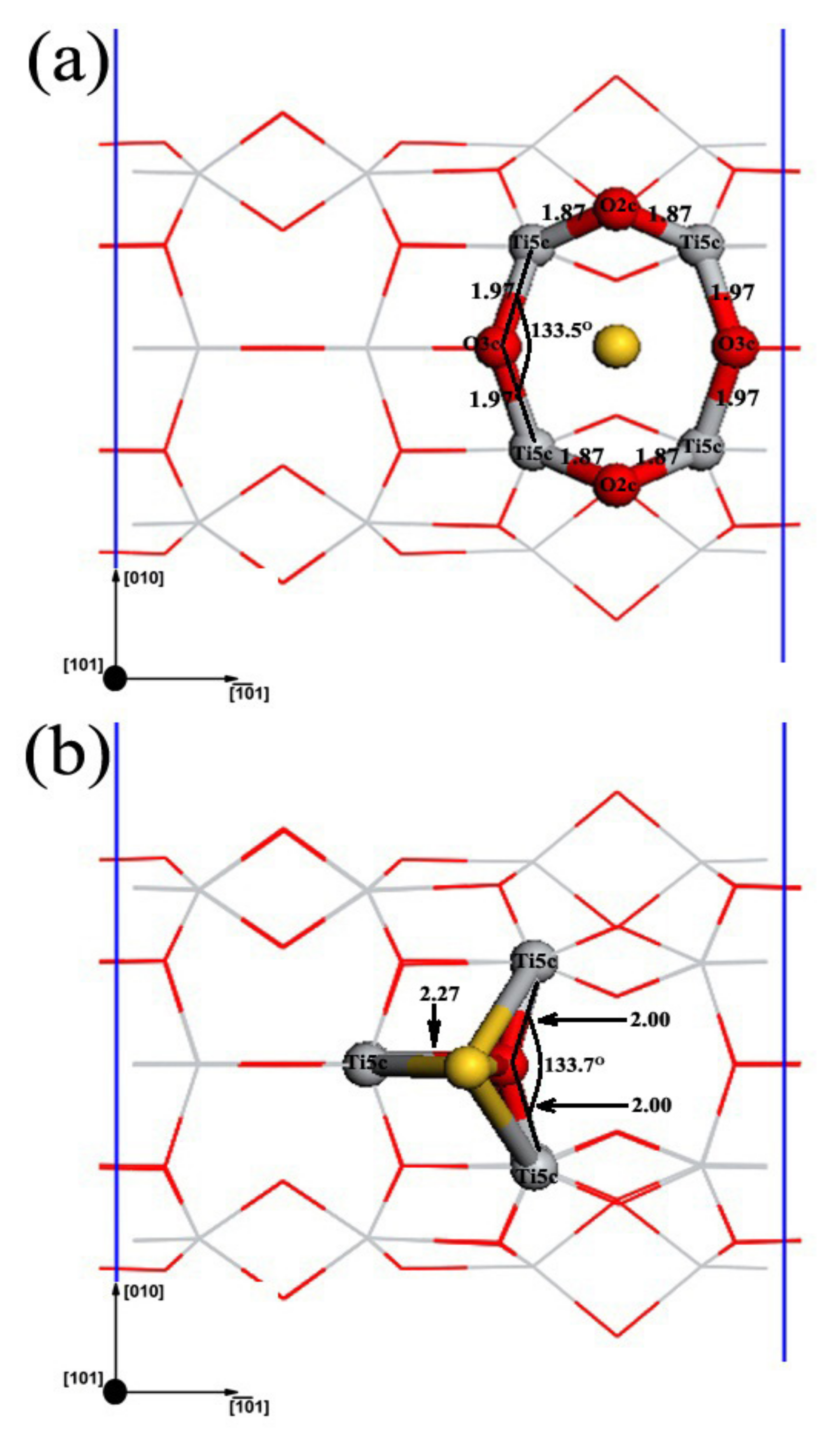
Two different stable adsorption structures were found for a single Au adatom on the TiO2NT (6,0) surface, as shown in Figure 2: a symmetric bridging site between two edge 2cO atoms in the 1 ¯ 01 direction, Au1(O,O), and the other right on top of a 3cO atom, as well as bonding to three 5cTi atoms, Au1(O,Ti). The adsorption energies of Au in these two configurations are listed in Table 1. For the two stable configurations, the adsorption energy of Au1(O,Ti) is 0.49 eV. Au1(O,Ti) is significantly more stable than Au1(O,O), which has an adsorption energy of about 0.20 eV. To illustrate the charge of adsorbed clusters and the charge distributions of clusters and related TiO2NT surface atoms, Mulliken charge analysis was employed. The Mulliken charges of Au and the nanotube surface atoms that directly associated with the Au adatom are shown in Table 1. Apparently, Au became negatively charged by receiving electrons in both configurations. Both types of O atoms binding to Au directly became less negative, and most 5cTi atoms became more positive, except for 5cTi3, which generally indicated the loss of electrons. This is consistent with Au adsorption on the anatase TiO2 (101) surface [3].
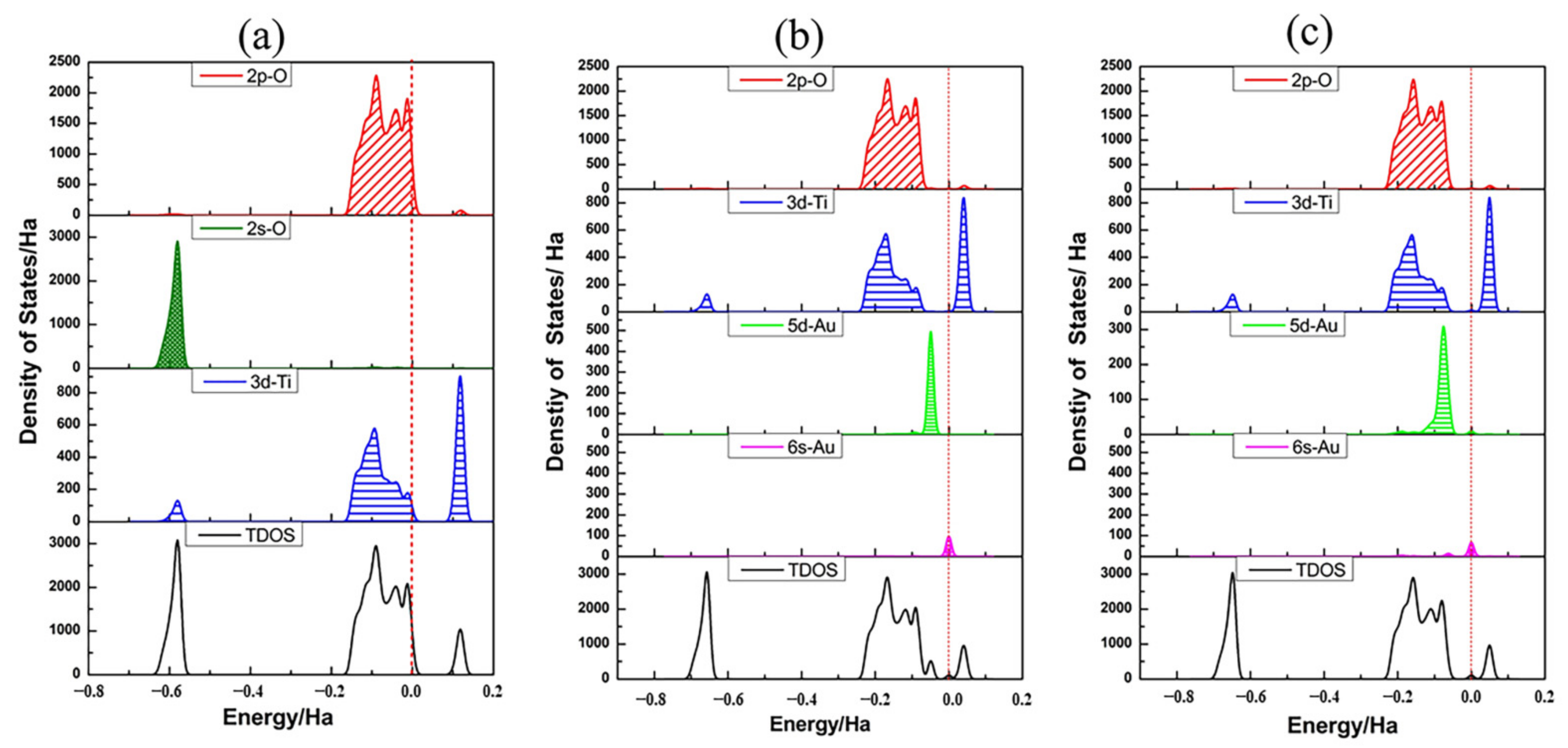
The DOS plots of bare TiO2NT and the adsorption system, and the PDOS plots of the Au adatom and the oxygen atoms and titanium atoms of TiO2 nanotube, are shown in Figure 3 and are used to further illustrate bonding characteristics. For the projection of 2p orbitals of oxygen, 3d orbitals of titanium and 5d orbitals of gold showed the major contribution to the PDOS in the energy range of interest. Therefore, projections of individual orbitals along with the DOS are shown. The zero on the energy axis of the plots corresponds to the Fermi level of the bare TiO2NT and is at the top of the valence band, marked with a red dashed line in the figures. As presented in Figure 3a, the bare TiO2NT is semiconducting, and the valence band mostly has a contribution by the O 2p orbital (red line in Figure 3a) with a small contribution from the Ti 3d orbital (blue line in Figure 3a). The conduction band is dominated by the Ti 3d orbital. The electron density contributed by the O 2s orbital in the low energy region from −0.8 Ha to −0.5 Ha has little effect on the electron structure regarding the Fermi level. Therefore, in the following parts, we do not discuss this any further. According to Figure 3b,c, after an Au atom was adsorbed on TiO2NTs, the TiO2NTs retained some semiconductor properties. The Fermi level moved close to the bottom of conduction band, and the valence band had mostly an O 2p character, but a new small peak of the Au 5d atom arose at the top of it. Correspondingly, a smaller peak of Au 6s appeared in the bottom of the conduction band at the zero of the energy axis. Compared with Au1(O,O), the Au 5d peak arose in the valence band separately. The valence band of Au1(O,Ti) contributed by the Au 5d peak, overlapped well with the O 2p and Ti 3d. It is thus more likely to cause electron transfer. The contribution of the Au 5d and 6s orbitals at the top valence band and bottom conduction band causes valence band broadening and band gap narrowing, which causes the adsorption band edge of TiO2NTs to red shift.
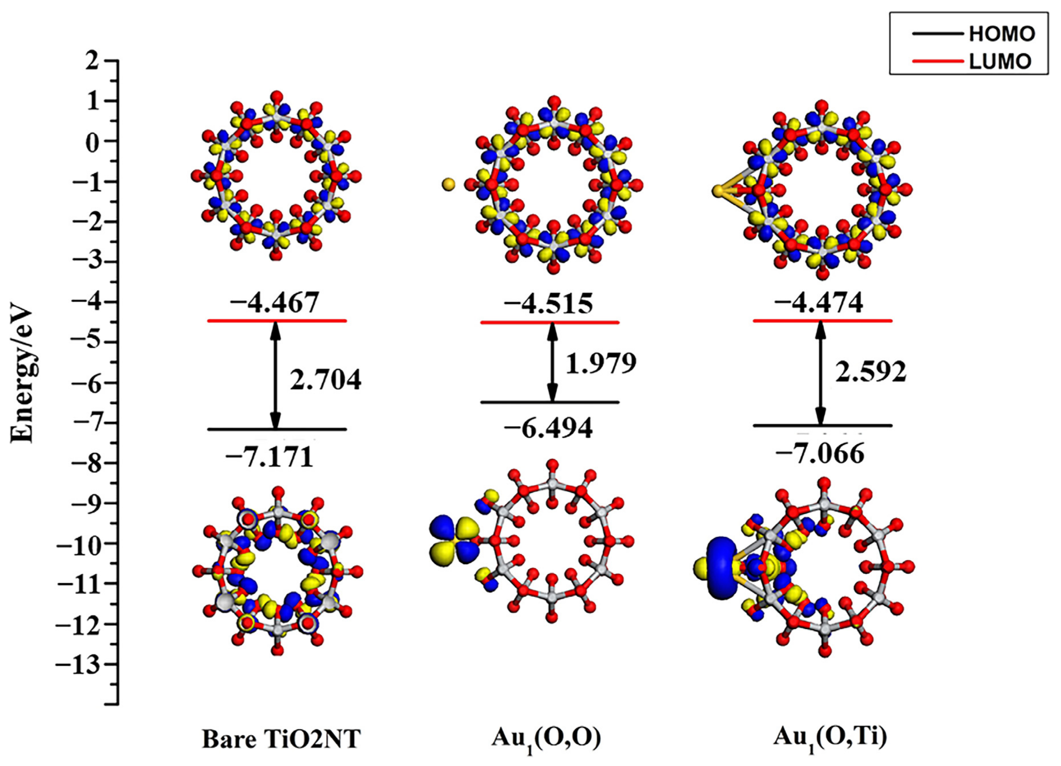
The highest occupied molecular orbital (HOMO) and the lowest unoccupied molecular orbital (LUMO) along with the energy gap of bare TiO2NTs and the adsorption system are shown in Figure 4. In the two adsorption configurations, the Au atoms are supported on the TiO2NT surface, reducing the energy gap from 2.704 eV to 1.979 eV and 2.592 eV, respectively. Further analysis shows that the d orbital of Au adatoms has an evident contribution to the HOMO orbital. The results are the same as the previous analysis of DOS. This leads to the energy of HOMO (Au1(O,O)) rising from −7.171 eV to −6.494 eV. Meanwhile, the major feature of HOMO is that the Au 5d orbital as well as the O 2p orbital replaced the main contribution of O 2p. The energy of LUMO (Au1(O,O)) decreases from −4.467 eV to −4.515 eV. The 3 d x 2 y 2 orbital of Ti gives the contribution to the bottom of the conduction band. The character of the 6s orbital of Au was not obviously observed in the LUMO orbital.
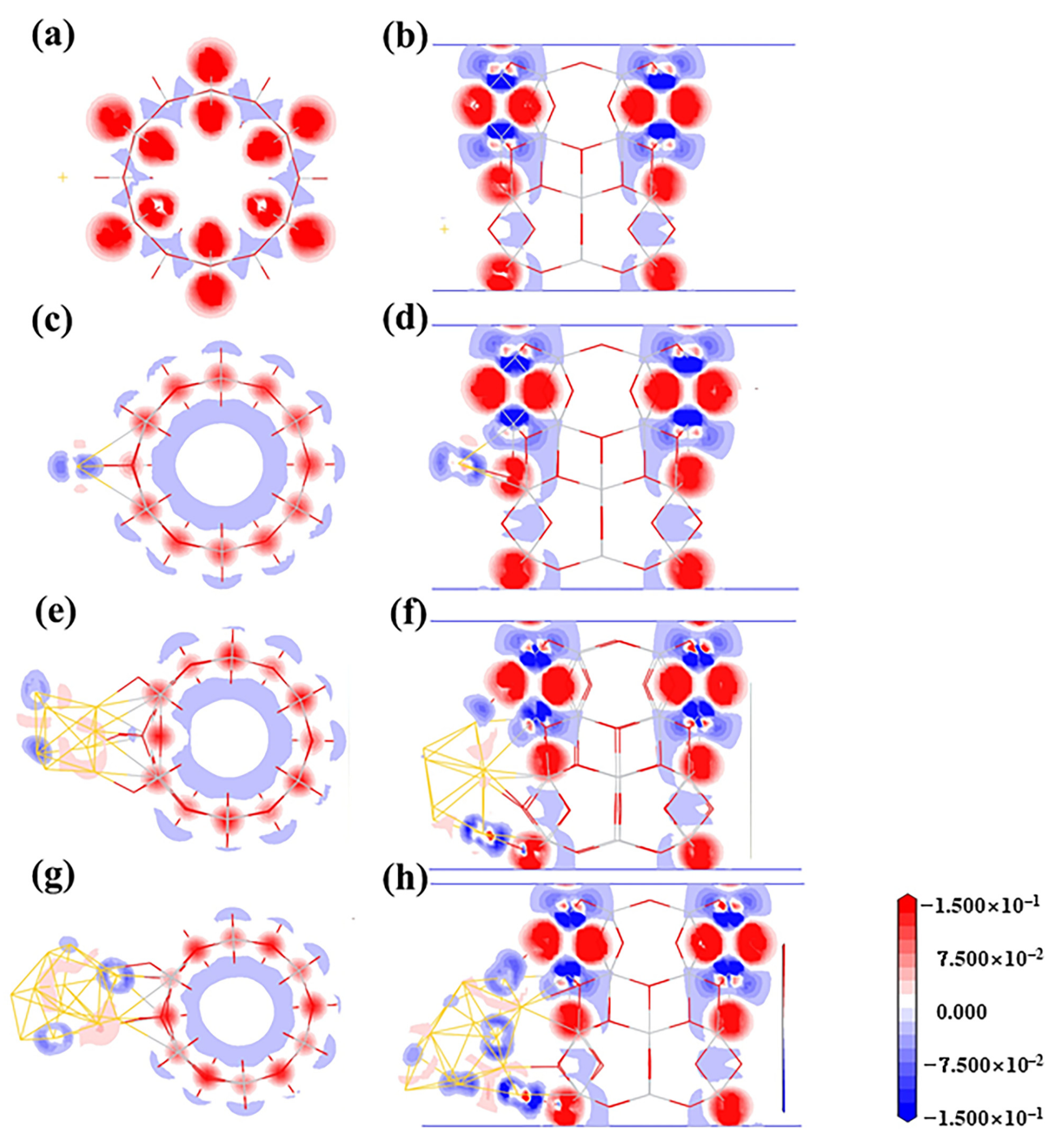
The bonding characteristics of the adsorption system are further demonstrated in the electron deformation density (EDD) contour maps in Figure 5. The EDD contour maps were defined as the total density by subtracting the isolated atoms’ electron density. Compared with the Au1(O,O), which has no significant bonding between Au atoms, and 2cO atoms deposited on the TiO2NT surface, the Au1(O,Ti) has an obvious depletion of electron density when the 3cO 2p orbital is aligned with the Au–3cO bond direction. Additionally, the Au atom was surrounded by a small number of electrons, which indicated the electron transfer from TiO2NTs to gold nano-clusters.

3.3. Structures of Au8/TiO2NT

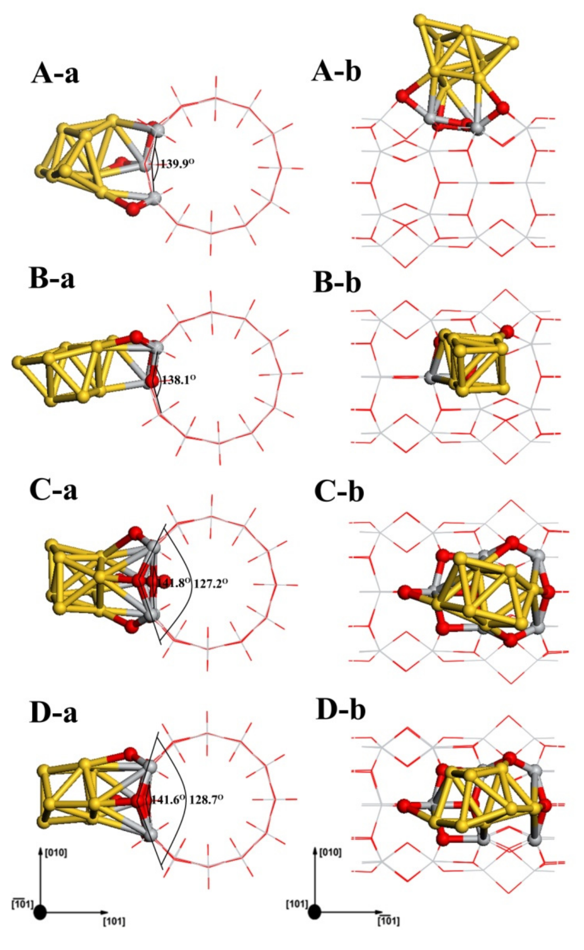
Figure 6 shows four different configurations of Au8 clusters adsorbed on the TiO2NT surface. The structures of Au8 in the four adsorption systems still maintain the biplanar conformation. The adsorption energy and Mulliken charge analysis for all these structures are listed in Table 2. Au8-A(2cO,3cO,2cO) is the most stable configuration for the Au8/TiO2NT systems, as shown in Figure 6(A-a,A-b). In this structure, three Au atoms as an adsorption layer bond to TiO2NT surface atoms, and the oxygen atoms of the TiO2NT surface which interacted with the Au8-A were 2cO, 3cO, and 2cO, respectively. In the structure shown in Figure 6(B-a,B-b), Au8-B(2cO,5cTi) has an adsorption energy of about 0.86 eV, slightly smaller than Au8-A, which has an adsorption energy of 1.11 eV. For the adsorption configuration of Au8-B, similar to Au8-A, there was an adsorption layer consisting of three Au atoms from the side direction of original Au8 biplanar binding to the TiO2NT directly. The third structure, Au8-C(2cO,2cO,3cO), which is displayed in Figure 6(C-a,C-b), is almost as stable as Au8-B. The energy difference between the two structures is merely 0.05 eV. In Au8-C, the adsorption layer is made up by four Au atoms as the bottom layer connecting with the TiO2NT surface. Both the bottom and top layer are part of the rhombus. The fourth structure, Au8-D(2cO,2cO,3cO), is a result of the relaxation by five Au atoms of Au8 biplanar parallel to the axial of TiO2NTs. Au8-D, as a local minimum, has similar binding sites to Au8-C, and is evidently less stable than the three previous structures. Noticeably, the adsorption of Au adatoms caused the TiO2NT surface’s deformation; the 3cO atoms which bonded with Au adatoms were pulled off of the surface of TiO2NT. Meanwhile, the other 3cO atoms which have no relation with the Au8 clusters were “pushed” into a slightly concave formation. This phenomenon can be found in Figure 6. According to Table 2, the Au8 clusters in four structures were negatively charged. Based on analysis of Au nanocluster size with Mulliken atomic charge and adsorption energy, for Au8 clusters, not only transfer charges but also adsorption energies were increased, with clusters enlarging. Compared to Au1 absorption systems with a charge of about −0.060 au and −0.075 au, respectively, there was a remarkable increase in the electron transfer to Au8 clusters. The maximum charge is −0.424 au for the Au8-C structure. This phenomenon suggested that more charge transfer will be required to enlarge the size of Aun nanoclusters to a certain degree. The interatomic charge distributions of related TiO2NT surface atoms were analyzed in detail. Apart from a few TiO2NT surface atoms, there are two main trends in atomic charge redistribution after the adsorption of Au8 clusters: electron transfer to oxygen atoms, and titanium losing electrons and showing greater positive charge.
PDOSs of Au8 clusters as well as the associated TiO2NT surface atoms in all four adsorption structures are plotted in Figure 7. The mixing between the O 2p orbital and Au 5d6s states spans the whole energy range of the valence band. Compared with the PDOS of a single Au adatom, the intensity of Au8 clusters at the Fermi level was greatly increased. The Au clusters’ 6s states make a dominating contribution to the states for the gap and are closely related to the Fermi level. The fact is that the energy gap of bare TiO2NTs almost disappears in all four adsorption systems. This indicates that metallization of the nanojunction Au8-TiO2NT system occurs, and therefore further increases tunnelling currents [66].
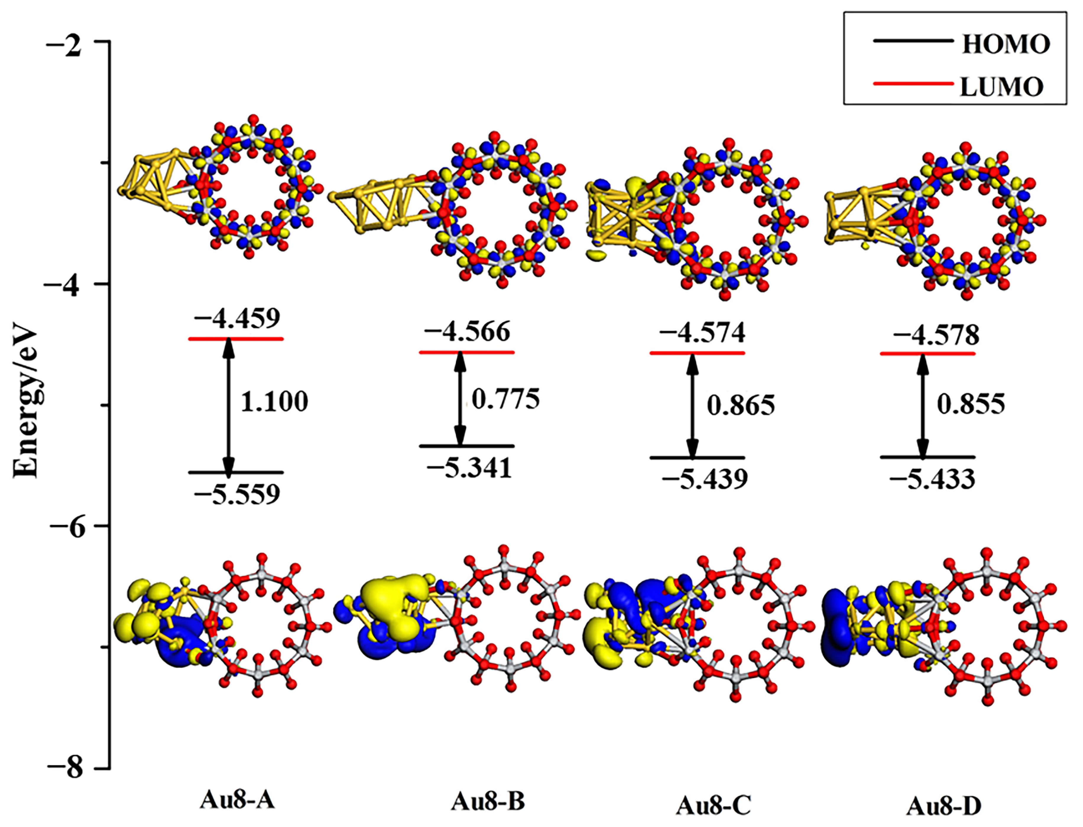
For more detailed analysis, the molecular orbital diagrams of HOMO and LUMO along with band gaps of the adsorption systems are shown in Figure 8. As the Au8 clusters adsorb on the TiO2NT surface, the contribution of metal clusters to the HOMO and the LUMO of the Fermi level is increased. As in the analysis of DOS, the band gap of the Au8–TiO2NT nanojunction was below 1.10 eV; Au8 clusters narrowed the band gap of the system more efficaciously than a single Au adatom. From the EDD contour maps of the Au8 adsorption system in Figure 5e,f, it can be found that Au8 clusters obtained electrons from TiO2NTs. In addition to the electron cloud distribution in Au8 nanoclusters, the Au atoms which have direct bonding with TiO2NT surface atoms show obvious electron accumulation, such as a Au8-C structure, as shown in Figure 5f.

3.4. Structures of Au13/TiO2NT

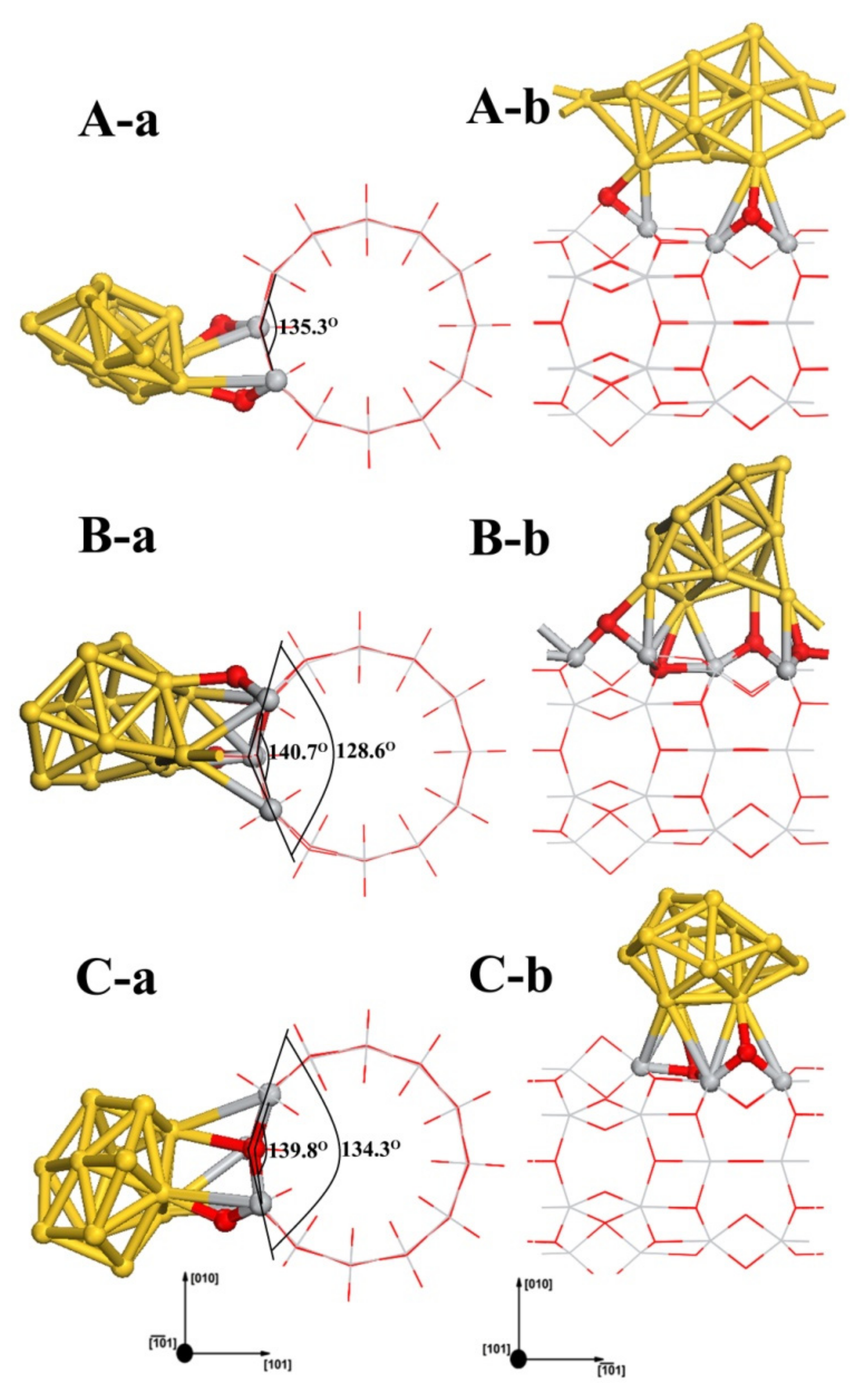
Au13 clusters in the gas phase have two stable 3D arrangements: icosahedrons and cuboctahedrons. There is no energy barrier between these two configurations. In our study, the icosahedrons deformed into a distorted face-centered cubic structure after geometry optimization. Au13 clusters possessing the more stable configuration of cuboctahedrons were selected to construct the Au13/TiO2NT system. Three stable adsorption configurations for Au13/TiO2NTs were obtained. The investigated configurations for the three adsorption systems are displayed in Figure 9. We can find that the condition of TiO2NT surface oxygen atoms which bind with the cluster is similar to the Au8-A(2cO,3cO,2cO). For the Au13-A(2cO,2cO) configuration, in which the cluster is parallel to the TiO2NT axial, Au13 bonded to two oxygen atoms on the nanotube surface and possessed the conformation with Au atoms spreading on the outside of nanotube surface, which is energetically preferred (see Table 3). In Au13-B(2cO,3cO,2cO,3cO), the absorbed Au13 cluster is similar to a cage-like structure [67,68], with four Au atoms directly bonding to the TiO2NT surface. Since the cage-like structure covers less area of the TiO2 nanotube than the flat geometry does, the density of the interfacial sites of the former is less than that of the latter. Although the cage-like structure is slightly less energetically favored than one of the geometries considered here, when the interface is considered as the controlling parameter, the cage-like Au13 nanoclusters can be expected to be more active than the other one for catalytic reactions. For optimized Au13-C(3cO,2cO) configuration, it also presents as a cage-like configuration. Au13 is adsorbed with a three-coordination oxygen atom and a two-coordination bridge oxygen atom, as shown in Figure 9C. The interaction of the Au13 with the nanotube surface was further analyzed with Mulliken charges. The adsorption energy for these structures and the Mulliken charges on the Au atoms and the binding atoms of TiO2NT are summarized in Table 3. Au13/TiO2NT systems have greater adsorption energy than Au8 and Au1 systems (see Table 3). This indicates that increasing the number of Au atoms can enhance the stabilization of the adsorption system and the size scope of Au clusters according to the results of this study for the Au nanoclusters. According to Table 3, with previous Mulliken charge analysis results of Au1 and Au8, the Au13 clusters became negative after being absorbed on TiO2NTs. However, the number of electrons transferred experiences no change. The interatomic charge distributions of related TiO2NT surface atoms are shown in Table 3. The two main trends of atomic charge redistribution after the adsorption of Au13 clusters are: electron transfer to oxygen atoms and titanium losing electrons and showing a more positive charge, except for a few TiO2NT surface atoms, which is similar to the Au8 system. For further details, we integrated Mulliken charge analysis with deformation density (see Figure 5g,h); noticeably, there are significant electrons missing on the three coordination oxygen atoms, while the connected Au atoms obtain electrons, which are highlighted using a red dashed line in the EDD contour maps in Figure 5h.
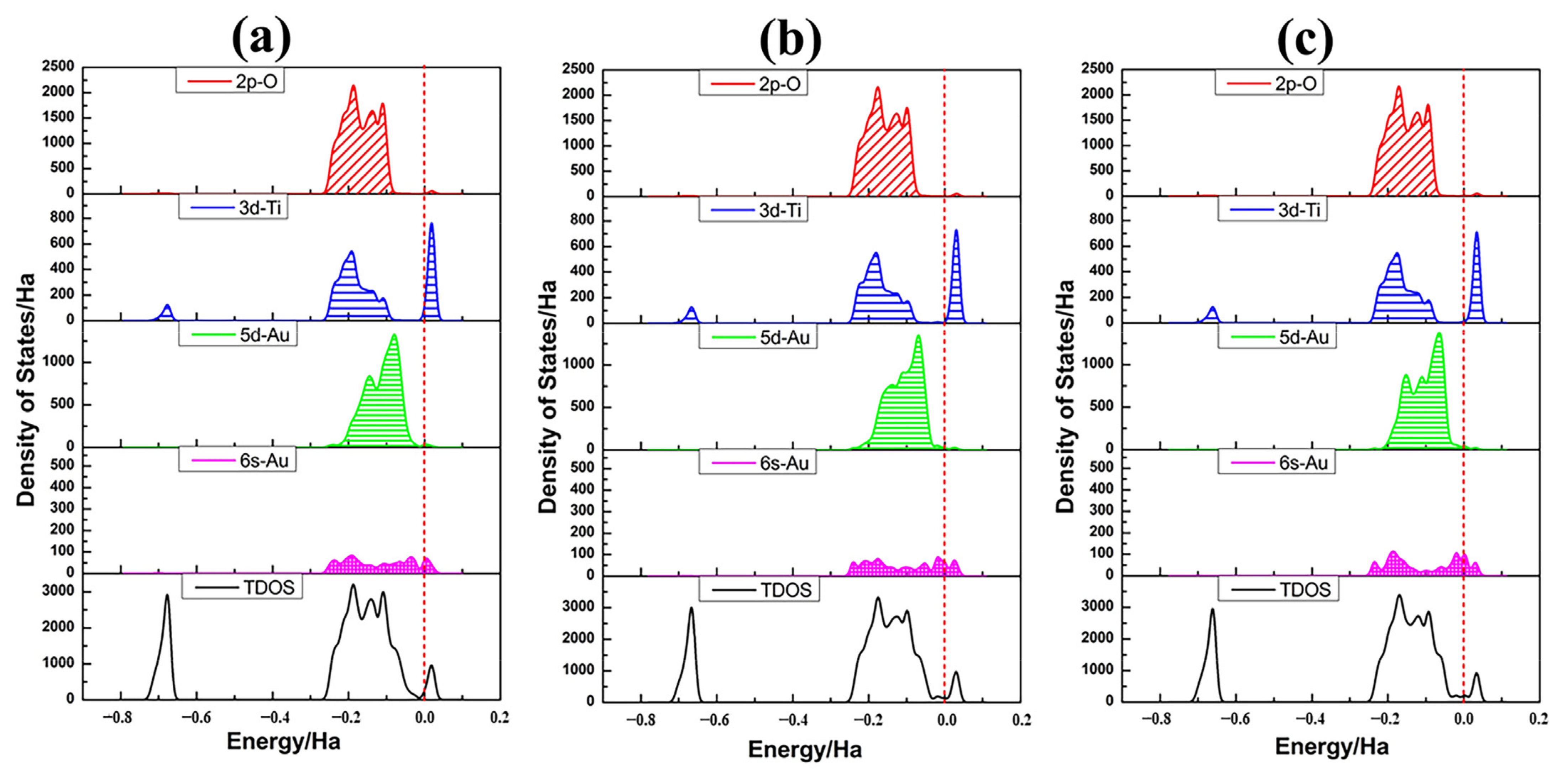
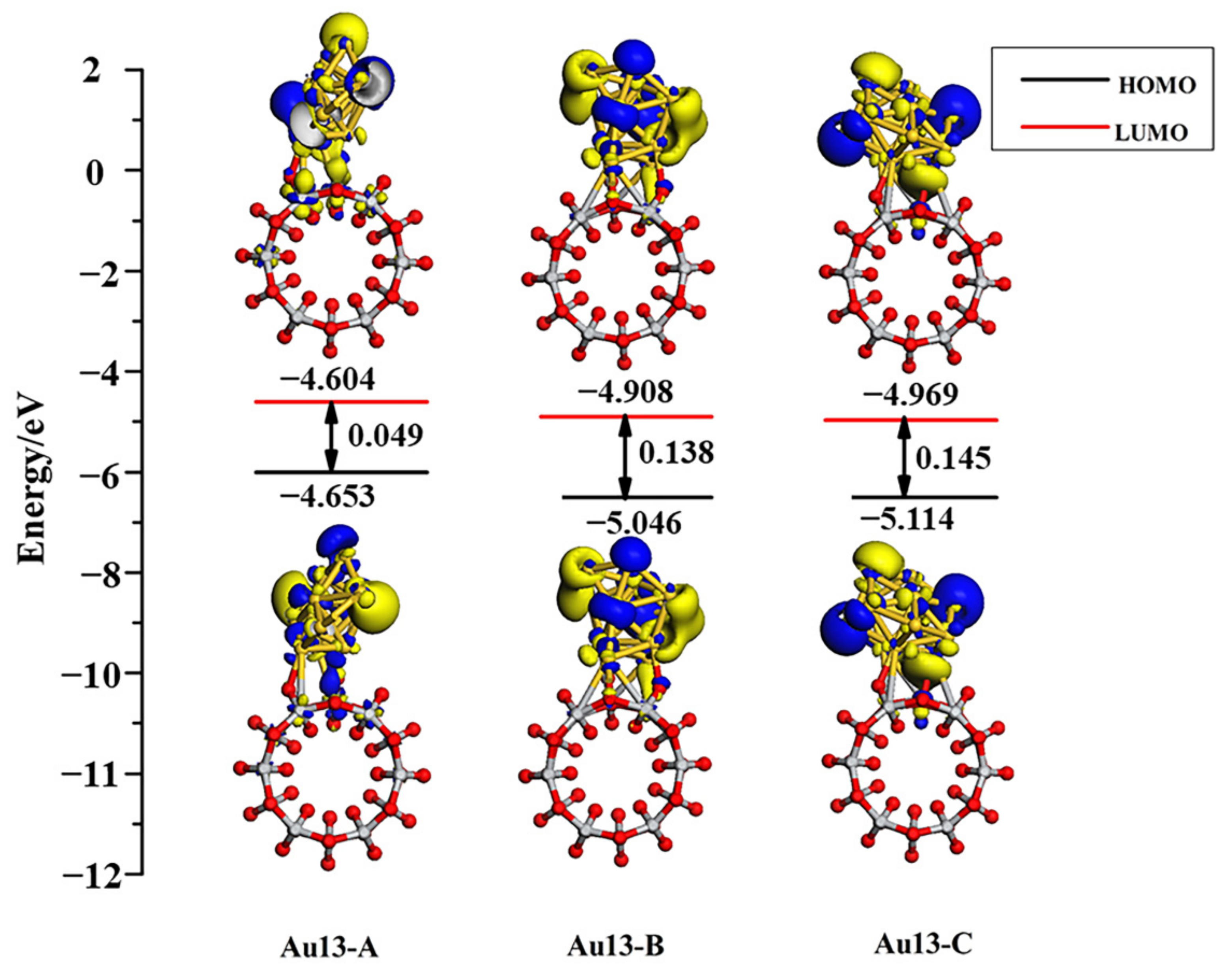
Figure 10 shows the PDOS of Au13 clusters and connecting surface atoms of TiO2NT along with the DOS of adsorption system. 5d-Au has a contribution to the top of the valence band and overlaps well with the O 2p orbital for all three adsorption structures. With the electron density of 5d6s-Au being raised, the contribution from Au atoms in the valence band and the conduction band was more and more obvious. The Au13 cluster adsorbed onto the TiO2NT surface will have an excellent performance in electron transport. The HOMO and LUMO orbital diagrams of adsorption systems, as shown in Figure 11, visually illustrate the orbital analysis results given the density of states. Au13 nanoclusters contribute to the valence band and the conduction band, along with the increase in the number of gold atoms. HOMO and LUMO orbitals are mainly provided by the Au nanoclusters. Compared with the Au8/TiO2NT system, the system’s energy is further decreased, particularly for the Au13-A configuration, which downgraded the energy gap to 0.049 eV, far below the maximum energy value of the visible light absorption.

4. Conclusions

In summary, Aun/TiO2NTsystems are studied using density functional theory to characterize the effect of the adsorption of Aun (n = 1, 8, 13) clusters on the geometric and electronic structures of anatase TiO2NT. Our results show that a single Au adatom prefers the top position of 3cO as well as the bridging 2cO–2cO site of the TiO2NT surface. Adsorbed Au8 maintains a distorted biplanar configuration. The strong interaction between Aun and atoms of the nanotube surface causes deformation of TiO2NT. Au13 is adsorbed in a cage-like structure and has a tendency to spread out on the wetted nanotube surface.
The adsorption energy is increased as the number of Au atoms increases linearly, and increases in the size of Aun clusters are conducive to stabilizing the load systems. The peaks at the Fermi level of the valence top and the conduction bottom come mainly from the contribution of 5d6s-Au atoms. The 5d6s orbital of impurities’ electronic state density caused valence widening and band gap narrowing. The band gap of the three most stable structures of adsorption systems Au1-A (2.592 eV), Au8-A (1.100 eV), and Au13-A (0.049 eV) decreased compared to bare TiO2NTs. This causes TiO2NTs to achieve a visible light response. Molecular orbital diagrams intuitively verify the obviously increasing contribution to HOMO and LUMO orbitals with the increase in gold atoms. Our present results serve as a possible indicator that the nanojunction TiO2NT/Aun cluster, as a potential photoelectric device, possesses better energy and charge transmission performance.

Author Contributions

Conceptualization, G.Z.; methodology, G.Z.; validation, G.Z.; investigation, G.Z. and Y.W.; data curation, G.Z. and Y.W.; writing—original draft preparation, Y.W.; writing—review and editing, G.Z.; supervision, G.Z.; project administration, G.Z. All authors have read and agreed to the published version of the manuscript.

Funding

This research was funded by the National Natural Science Foundation of China (NSFC), grant number 51973127.

Institutional Review Board Statement

Not applicable.

Informed Consent Statement

Not applicable.

Data Availability Statement

Not applicable.

Conflicts of Interest

The authors declare no conflict of interest.

References

  1. Gong, X.B. Small Au and Pt Clusters at the Anatase TiO2 (101) Surface: Behavior at Terraces, Steps, and Surface Oxygen Vacancies. J. Am. Chem. Soc. 2008, 130, 370–381. [Google Scholar] [CrossRef]
  2. Han, Y.; Liu, C.; Ge, Q. Interaction of Pt Clusters with the Anatase TiO2 (101) Surface: A First Principles Study. J. Phys. Chem. B 2006, 110, 7463–7472. [Google Scholar] [CrossRef] [PubMed]
  3. Vittadini, A.; Selloni, A. Small Gold Clusters on Stoichiometric and Defected TiO2 Anatase (101) and Their Interaction with CO: A Density Functional Study. J. Chem. Phys. 2002, 117, 353–361. [Google Scholar] [CrossRef]
  4. Zhao, Q.; Li, M.; Chu, J.; Jiang, T.; Yin, H. Preparation, Characterization of Au (or Pt)-Loaded Titania Nanotubes and Their Photocatalytic Activities for Degradation of Methyl Orange. Appl. Surf. Sci. 2009, 255, 3773–3778. [Google Scholar] [CrossRef]
  5. Goldman, N.; Browning, N.D. Gold Cluster Diffusion Kinetics on Stoichiometric and Reduced Surfaces of Rutile TiO2(110). J. Phys. Chem. C 2011, 115, 11611–11617. [Google Scholar] [CrossRef] [Green Version]
  6. Zhang, Z.; Tang, W.; Neurock, M.; Yates, J.T. Electric Charge of Single Au Atoms Adsorbed on TiO2 (110) and Associated Band Bending. J. Phys. Chem. C 2011, 115, 23848–23853. [Google Scholar] [CrossRef]
  7. Çakir, D.; Gülseren, O. Adsorption of Pt and Bimetallic PtAu Clusters on the Partially Reduced Rutile (110) TiO2 Surface: A First-Principles Study. J. Phys. Chem. C 2012, 116, 5735–5746. [Google Scholar] [CrossRef] [Green Version]
  8. Matthey, D.; Wang, J.G.; Wendt, S.; Matthiesen, J.; Schaub, R.; Lægsgaard, E.; Hammer, B.; Besenbacher, F. Enhanced Bonding of Gold Nanoparticles on Oxidized TiO2 (110). Science 2007, 315, 1692–1696. [Google Scholar] [CrossRef] [Green Version]
  9. Fu, C.; Li, M.; Li, H.; Li, C.; Wu, X.G.; Yang, B. Fabrication of Au Nanoparticle/TiO2 Hybrid Films for Photoelectrocatalytic Degradation of Methyl Orange. J. Alloys Compd. 2017, 692, 727–733. [Google Scholar] [CrossRef]
  10. Galeanoa, L.; Valencia, S.; Restrepo, G.; Marin, J.M. Dry-co-Grinding of Doped TiO2 With Nitrogen, Silicon or Selenium for Enhanced Photocatalytic Activity under UV/Visible and Visible Light Irradiation for Environmental Applications. Mater. Sci. Semicond. Process. 2019, 91, 47–57. [Google Scholar] [CrossRef]
  11. Maolanon, R.; Wongwiriyapan, W.; Pratontep, S. TiO2/Pt/TiO2 Sandwich Nanostructures: Towards Alcohol Sensing and UV Irradiation-Assisted Recovery. J. Chem. 2017, 2017, 8545690. [Google Scholar] [CrossRef] [Green Version]
  12. Saeed, K.; Khan, I.; Gul, T.; Sadiq, M. Efficient Photodegradation of Methyl Violet Dye Using TiO2/Pt and TiO2/Pdphotocatalysts. Appl. Water Sci. 2017, 7, 3841–3848. [Google Scholar] [CrossRef]
  13. Pan, X.; Chen, X.; Yi, Z. Defective, Porous TiO2 Nanosheets with Pt Decoration as an Efficient Photocatalyst for Ethylene Oxidation Synthesized by a C3N4 Templating Method. ACS Appl. Mater. Interfaces 2016, 8, 10104–10108. [Google Scholar] [CrossRef]
  14. Maeda, K.; Domen, K. Photocatalytic Water Splitting: Recent Progress and Future Challenges. J. Phys. Chem. Lett. 2010, 1, 2655–2661. [Google Scholar] [CrossRef]
  15. Teoh, W.Y.; Scott, J.A.; Amal, R. Progress in Heterogeneous Photocatalysis: From Classical Radical Chemistry to Engineering Nanomaterials and Solar Reactors. J. Phys. Chem. Lett. 2012, 3, 629–639. [Google Scholar] [CrossRef]
  16. Miyasaka, T. Toward Printable Sensitized Mesoscopic Solar Cells: Light-Harvesting Management with Thin TiO2 Films. J. Phys. Chem. Lett. 2011, 2, 262–269. [Google Scholar] [CrossRef]
  17. Mora-Seró, I.; Bisquert, J. Breakthroughs in the Development of Semiconductor-Sensitized Solar Cells. J. Phys. Chem. Lett. 2010, 1, 3046–3052. [Google Scholar] [CrossRef]
  18. Braga, A.; Giménez, S.; Concina, I.; Vomiero, A.; Mora-Seró, I. Panchromatic Sensitized Solar Cells Based on Metal Sulfide Quantum Dots Grown Directly on Nanostructured TiO2 Electrodes. J. Phys. Chem. Lett. 2011, 2, 454–460. [Google Scholar] [CrossRef]
  19. Mowbray, D.J.; Martínez, J.I.; Calle-Vallejo, F.; Rossmeisl, J.; Thygesen, K.S.; Jacobsen, K.W.; Nørskov, J.K. Trends in Metal Oxide Stability for Nanorods, Nanotubes, and Surfaces. J. Phys. Chem. C 2011, 115, 2244–2252. [Google Scholar] [CrossRef] [Green Version]
  20. Yu, J.G.; Hai, Y.; Cheng, B. Enhanced Photocatalytic H2-Production Activity of TiO2 by Ni(OH)2 Cluster Modification. J. Phys. Chem. C 2011, 115, 4953–4958. [Google Scholar] [CrossRef]
  21. Petrik, N.G.; Kimmel, G.A. Electron-and Hole-Mediated Reactions in UV-Irradiated O2 Adsorbed on Reduced Rutile TiO2 (110). J. Phys. Chem. C 2011, 115, 152–164. [Google Scholar] [CrossRef]
  22. Chrétien, S.; Metiu, H. Electronic Structure of Partially Reduced Rutile TiO2 (110) Surface: Where Are the Unpaired Electrons Located? J. Phys. Chem. C 2011, 115, 4696–4705. [Google Scholar] [CrossRef]
  23. Deskins, N.A.; Rousseau, R.; Dupuis, M. Defining the Role of Excess Electrons in the Surface Chemistry of TiO2. J. Phys. Chem. C 2010, 114, 5891–5897. [Google Scholar] [CrossRef]
  24. Asahi, R.; Taga, Y.; Mannstadt, W.; Freeman, A.J. Electronic and Optical Properties of Anatase TiO2. Phys. Rev. B 2000, 6, 7459–7465. [Google Scholar] [CrossRef]
  25. Tang, H.; Berger, H.; Schmid, P.E.; Lévy, F. Photoluminescence in TiO2 Anatase Single Crystals. Solid State Commun. 1993, 87, 847–850. [Google Scholar] [CrossRef]
  26. Pu, Y.C.; Wang, G.; Chang, K.D.; Ling, Y.; Lin, Y.K.; Fitzmorris, B.C.; Liu, C.M.; Lu, X.; Tong, Y.; Zhang, J.Z.; et al. Au Nanostructure-Decorated TiO2 Nanowires Exhibiting Photoactivity across Entire UV-visible Region for Photoelectrochemical Water Splitting. Nano Lett. 2013, 13, 3817–3823. [Google Scholar] [CrossRef] [PubMed]
  27. Malato, S.; Fernández-Ibáñez, P.; Maldonado, M.I.; Blanco, J.; Gernjak, W. Decontamination and Disinfection of Water by Solar Photocatalysis. Recent Overview and Trends. Catal. Today 2009, 147, 1–59. [Google Scholar] [CrossRef]
  28. Leary, R.; Westwood, A. Carbonaceous Nanomaterials for the Enhancement of TiO2 Photocatalysis. Carbon 2011, 49, 741–772. [Google Scholar] [CrossRef]
  29. Gao, L.D.; Le, Y.; Wang, J.X.; Chen, J.F. Preparation and Characterization of Titanium Nanotubes with Mesostructured Walls. Mater. Lett. 2006, 60, 3882–3886. [Google Scholar] [CrossRef]
  30. Nunzi, F.; Angelis, F.D. DFT Investigations of Formic Acid Adsorption on Single-Wall TiO2 Nanotubes: Effect of the Surface Curvature. J. Phys. Chem. C 2011, 115, 2179–2186. [Google Scholar] [CrossRef]
  31. Shankar, K.; Bandara, J.; Paulose, M.; Wietasch, H.; Varghese, O.K.; Mor, G.K.; LaTempa, T.J.; Thelakkat, M.; Grimes, C.A. Highly Efficient Solar Cells using TiO2 Nanotube Arrays Sensitized with a Donor-Antenna Dye. Nano Lett. 2008, 8, 1654–1659. [Google Scholar] [CrossRef]
  32. Macak, J.M.; Zlamal, M.; Krysa, J.; Schmuki, P. Self-Organized TiO2 Nanotube Layers as Highly Efficient Photocatalysts. Nano Micro Small 2007, 3, 300–304. [Google Scholar] [CrossRef]
  33. Kuang, D.; Brillet, J.R.M.; Chen, P.; Takata, M.; Uchida, S.; Miura, H.; Sumioka, K.; Zakeeruddin, S.M.; Grätzel, M. Application of Highly Ordered TiO2 Nanotube Arrays in Flexible Dye-Sensitized Solar Cells. ACS Nano 2008, 2, 1113–1116. [Google Scholar] [CrossRef]
  34. Hossain, F.M.; Evteev, A.V.; Belova, I.V.; Nowotny, J.; Murch, G.E. Electronic and Optical Properties of Anatase TiO2 Nanotubes. Comput. Mater. Sci. 2010, 48, 854–858. [Google Scholar] [CrossRef]
  35. Chen, H.M.; Chen, C.K.; Chang, Y.C.; Tsai, C.W.; Liu, R.S.; Hu, S.F.; Chang, W.S.; Chen, K.H. Quantum Dot Monolayer Sensitized ZnO Nanowire-Array Photoelectrodes: True Efficiency for Water Splitting. Angew. Chem. Int. Ed. 2010, 49, 5966–5969. [Google Scholar] [CrossRef]
  36. Lee, Y.L.; Chi, C.F.; Liau, S.Y. CdS/CdSe Co-Sensitized TiO2 Photoelectrode for Efficient Hydrogen Generation in a Photoelectrochemical Cell. Chem. Mater. 2010, 22, 922–927. [Google Scholar] [CrossRef]
  37. Gao, Z.D.; Liu, H.F.; Li, C.Y.; Song, Y.Y. Biotemplated Synthesis of Au Nanoparticles–TiO2 Nanotube Junctions for Enhanced Direct Electrochemistry of Heme Proteins. Chem. Commun. 2013, 49, 774–776. [Google Scholar] [CrossRef]
  38. Shao, Z.; Wang, X.; Ren, S.; Tian, Z.; Fan, S.; Sun, S.; Liu, S.; Wang, Q. Improved Visible Solar Absorber Based on TiO2 Nanotube Film by Surface-Loading of Plasmonic Au Nanoparticles. J. Appl. Phys. 2013, 114, 063510. [Google Scholar] [CrossRef]
  39. Chen, S.; Malig, M.; Tian, M.; Chen, A. Electrocatalytic Activity of PtAu Nanoparticles Deposited on TiO2 Nanotubes. J. Phys. Chem. C 2012, 116, 3298–3304. [Google Scholar] [CrossRef]
  40. Bao, H.H. Microwave Synthesis and Charaterization of Ag, Au, Pt nanoparticles Supported on TiO2 Nanotubes. Chin. J. Inorg. Chem. 2005, 21, 374–378. [Google Scholar]
  41. Xiao, F. An Efficient Layer-by-Layer Self-Assembly of Metal-TiO2 Nanoring/Nanotube Heterostructures, M/T-NRNT (M = Au, Ag, Pt), for Versatile Catalytic Applications. Chem. Commun. 2012, 48, 6538–6540. [Google Scholar] [CrossRef]
  42. Zhu, B.L.; Guo, Q.; Wang, S.; Zheng, X.; Zhang, S.; Wu, S.; Huang, W. Synthesis of MetalDdoped TiO2 Nanotubes and Their Catalytic Performance for Low-Temperature CO Oxidation. React. Kinet. Catal. Lett. 2006, 88, 301–308. [Google Scholar] [CrossRef]
  43. Chen, X.; Liu, W.; Tang, L.; Wang, J.; Pan, H.; Du, M. Electrochemical Sensor for Detection of Hydrazine Based on Au@Pd Core–Shell Nanoparticles Supported on Amino-Functionalized TiO2 Nanotubes. Mater. Sci. Eng. C 2014, 34, 304–310. [Google Scholar] [CrossRef] [PubMed]
  44. Yu, J.; Xiang, Q.; Zhou, M. Preparation, Characterization and Visible-Light-Driven Photocatalytic Activity of Fe-Doped Titaniananorods and First-Principles Study for Electronic Structures. App. Catal. B Environ. 2009, 90, 595–602. [Google Scholar] [CrossRef]
  45. Diebold, U. The Surface Science of Titanium Dioxide. Surf. Sci. Rep. 2003, 48, 53–229. [Google Scholar] [CrossRef]
  46. Diebold, U.; Lehman, J.; Mahmoud, T.; Kuhn, M.; Leonardelli, G.; Hebenstreit, W.; Schmid, M.; Varga, P. Intrinsic Defects on a TiO2 (110)(1×1) Surface and Their Reaction with Oxygen: A Scanning Tunneling Microscopy Study. Surf. Sci. 1998, 411, 137–153. [Google Scholar] [CrossRef]
  47. Hengerer, R.; Bolliger, B.; Erbudak, M.; Gratzel, M. Structure and Stability of the Anatase TiO2 (101) and (001) Surfaces. Surf. Sci. 2000, 460, 162–169. [Google Scholar] [CrossRef]
  48. Lazzeri, M.; Vittadini, A.; Selloni, A. Structure and Energetics of Stoichiometric TiO2 Anatase Surfaces. Phys. Rev. B 2001, 63, 155409. [Google Scholar] [CrossRef]
  49. Haruta, M. When Gold Is Not Noble: Catalysis by Nanoparticles. Chem. Rec. 2003, 3, 75–87. [Google Scholar] [CrossRef]
  50. De Sekhar, H.; Krishnamurty, S.; Sourav, P. Understanding the Reactivity Properties of Aun (6 ≤ n ≤ 13) Clusters Using Density Functional Theory Based Reactivity Descriptors. J. Phys. Chem. C 2010, 114, 6690–6703. [Google Scholar] [CrossRef]
  51. Sanchez, A.; Abbet, S.; Heiz, U.; Schneider, W.D.; Häkkinen, H.; Barnett, R.N.; Landman, U. When Gold Is Not Noble:  Nanoscale Gold Catalysts. J. Phys. Chem. A 1999, 103, 9573–9578. [Google Scholar] [CrossRef]
  52. Häkkinen, H.; Abbet, S.; Sanchez, A.; Heiz, U.; Landman, U. Structural, Electronic, and Impurity-Doping Effects in Nanoscale Chemistry: Supported Gold Nanoclusters. Angew. Chem. Int. Ed. 2003, 42, 1297–1300. [Google Scholar] [CrossRef]
  53. Yoon, B.; Häkkinen, H.; Landman, U.; Wörz, A.S.; Antonietti, J.M.; Abbet, S.; Judai, K.; Heiz, U. Charging Effects on Bonding and Catalyzed Oxidation of CO on Au8 Clusters on MgO. Science 2005, 307, 403–407. [Google Scholar] [CrossRef] [Green Version]
  54. Fernández, E.M.; Soler, J.M.; Garzón, I.L.; Balbás, L.C. Trends in the Structure and Bonding of Noble Metal Clusters. Phys. Rev. B 2004, 70, 165403. [Google Scholar] [CrossRef]
  55. Oviedo, J.; Palmer, R.E. Amorphous Structures of Cu, Ag, and Au Nanoclusters from First Principles Calculations. J. Chem. Phys. 2002, 117, 9548–9551. [Google Scholar] [CrossRef]
  56. Chang, C.M.; Chou, M.Y. Alternative Low-Symmetry Structure for 13-Atom Metal Clusters. Phys. Rev. Lett. 2004, 93, 133401–133404. [Google Scholar] [CrossRef]
  57. Shafai, G.; Hong, S.; Bertino, M.; Rahman, T.S. Effect of Ligands on the Geometric and Electronic Structure of Au13 Clusters. J. Phys. Chem. C 2009, 113, 12072–12078. [Google Scholar] [CrossRef] [Green Version]
  58. Perdew, J.P.; Burke, K.; Ernzerhof, M. Generalized Gradient Approximation Made Simple. Phys. Rev. Lett. 1996, 77, 3865–3868. [Google Scholar] [CrossRef] [Green Version]
  59. Delley, B. An Allelectron Numerical Method for Solving the Local Density Functional Forpolyatomic Molecules. J. Chem. Phys. 1990, 92, 508–517. [Google Scholar] [CrossRef]
  60. Delley, B. From Molecules to Solids with the DMol3 Approach. J. Chem. Phys. 2000, 113, 7756–7764. [Google Scholar] [CrossRef]
  61. Dong, C.; Li, X.; Qi, J. First-Principles Investigation on Electronic Properties of Quantum Dot-Sensitized Solar Cells Based on Anatase TiO2 Nanotubes. J. Phys. Chem. C 2011, 115, 20307–20315. [Google Scholar] [CrossRef]
  62. Monkhorst, H.J.; Pack, J.D. Special Points for Brillouin-Zone Integrations. Phys. Rev. B 1976, 13, 5188–5192. [Google Scholar] [CrossRef]
  63. Burdett, J.K.; Hughbanks, T.; Miller, G.J.; Richardson, J.W., Jr.; Smith, V. Structural-Electronic Relationships in Inorganic Solids: Powder Neutron Diffraction Studies of the Rutile and Anatase Polymorphs of Titanium Dioxide at 15 and 295 K. J. Am. Chem. Soc. 1987, 109, 3639–3646. [Google Scholar] [CrossRef]
  64. Evarestov, R.A.; Zhukovskii, Y.F.; Bandura, A.V.; Piskunov, S. Symmetry and Models of Single-Walled TiO2 Nanotubes with Rectangular Morphology. Cent. Eur. J. Phys. 2011, 9, 492–501. [Google Scholar] [CrossRef] [Green Version]
  65. Bandura, A.V.; Evarestov, R.A. From Anatase (101) Surface to TiO2 Nanotubes: Rolling Procedure and First Principles LCAO Calculations. Surf. Sci. 2009, 603, 117–120. [Google Scholar] [CrossRef]
  66. Cho, Y.; Kim, C.; Moon, H.; Choi, Y.; Park, S.; Lee, C.-K.; Han, S. Electronic Structure Tailoring and Selective Adsorption Mechanism of Metal-coated Nanotubes. Nano Lett. 2008, 8, 81–86. [Google Scholar] [CrossRef] [PubMed]
  67. Dong, Y.; Springborg, M. Global Structure Optimization Study on Au2–20. Eur. Phys. J. D 2007, 43, 15–18. [Google Scholar] [CrossRef]
  68. Hong, S.; Rahman, T.S. Rationale for the Higher Reactivity of Interfacial Sites in Methanol Decomposition on Au13/TiO2(110). J. Am. Chem. Soc. 2013, 135, 7629–7635. [Google Scholar] [CrossRef]
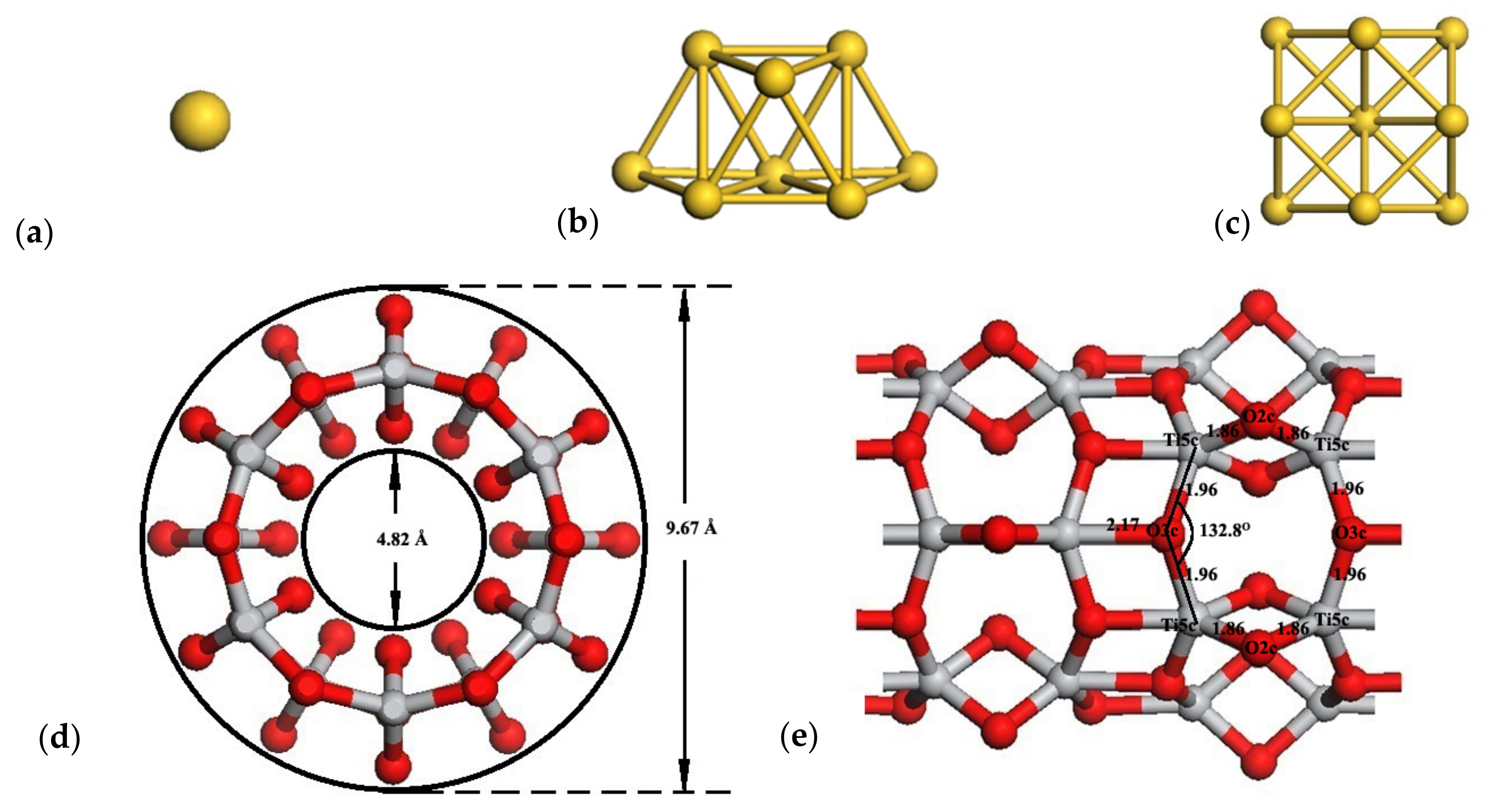
Figure 1. Optimized geometry of bare Au clusters and the bare TiO2NT (6,0). The first three configurations are: (a) Au1; (b) Au8biplanar; (c) Au13 cuboctahedral. (d,e) are the cross-sectional and the side view of the TiO2NT (6,0), respectively. The gold atoms are shown in gold, the oxygen atoms are displayed in red, while titanium atoms are presented in light gray.
Molecules 27 02756 g001
Figure 2. Top views of detailed adsorption structures for a single Au adatom on the TiO2NT (6,0) surface: (a) Au1(O,O); (b) Au1(O,Ti).
Molecules 27 02756 g002
Figure 3. Density of state profiles and the partial density of states of TiO2NT (6,0) and Au and relevant nanotube surface atoms for a single Au adatom in two different adsorption states: (a) bare TiO2NT (6,0), (b) Au1(O,O), (c) Au1(O,Ti). The black curve is the sum of PDOS of O atoms, Ti atoms, and Au atoms from the optimized bare TiO2NT (6,0)/Au systems, while the red curve indicates the 2p orbital of oxygen atoms, the dark green curve indicates the 2s orbital of oxygen atoms, the blue curve represents the 3d orbital of titanium atoms, the light green curve denotes the 5d orbital of gold atoms, and the magenta curve represents the 5s orbital of gold atoms, respectively. The Fermi level of bare TiO2NTs is set at 0 eV, as denoted in the red dashed line.
Molecules 27 02756 g003
Figure 4. HOMO and LUMO along with the energy gap of bare TiO2NT and two Au1 adsorption systems calculated at the Γ-point. The isovalue set is 0.025 electrons/Å3. The gold atoms are shown in gold, the oxygen atoms are displayed in red, while titanium atoms are presented in light gray. Blue and yellow regions represent the positive and negative parts of HOMO and LUMO respectively.
Molecules 27 02756 g004
Figure 5. Deformation density contour maps for the adsorption of Aun clusters on the TiO2NT (6,0) surface. The configurations are as follows: (a,c,e,g) are the cross-sectional views of Au1(O,O), Au1(O,Ti), Au8-C, and Au13-B, respectively; (b,d,f,h) are the side views of Au1(O,O), Au1(O,Ti), Au8-C, and Au13-B, respectively. Contour level is −0.015~0.015 au. In this plot, a loss of electrons is indicated in blue, while electron enrichment is indicated in red.
Molecules 27 02756 g005
Figure 6. Four adsorption geometries for Au8 clusters on the TiO2NT (6,0) are displayed as (AD). (a,b) depict the cross-sectional view and the side view of the Au8 cluster absorption systems, respectively. The cross-sectional views of four adsorption geometries are shown as (A-a,B-a,C-a,D-a), respectively. The side vies of four adsorption geometries are shown as (A-b,B-b,C-b,D-b), respectively.
Molecules 27 02756 g006
Figure 7. Density of state profiles and the partial density of states of Au8 and relevant nanotube surface atoms for Au8 clusters in four different adsorption states: (a) Au8-A(2cO,3cO,2cO); (b) Au8-B(2cO,5cTi); (c) Au8-C(2cO,2cO,3cO); (d) Au8-D(2cO,2cO,3cO). The detailed information is same as in Figure 3.
Molecules 27 02756 g007
Figure 8. HOMO and LUMO along with the energy gap of four Au8 adsorption systems calculated at the Γ-point. The isovalue set is 0.025 electrons/Å3.
Molecules 27 02756 g008
Figure 9. Four adsorption geometries for Au13 clusters on the TiO2NT (6,0) are displayed as (AC). (a,b) depict the cross-sectional view and the side view of the Au13 cluster absorption systems, respectively. The cross-sectional views of four adsorption geometries are shown as (A-a,B-a,C-a), respectively. The side vies of four adsorption geometries are shown as (A-b,B-b,C-b), respectively.
Molecules 27 02756 g009
Figure 10. Density of state profiles and the partial density of states of Au13 and relevant nanotube surface atoms for Au13 clusters in four different adsorption states: (a) Au13-A(2cO,2cO), (b) Au13-B(2cO,3cO,2cO,3cO), (c) Au13-C(3cO,2cO). The detailed information is the same as in Figure 3.
Molecules 27 02756 g010
Figure 11. HOMO and LUMO along with the energy gap of four Au13 adsorption systems calculated at the Γ-point. The isovalue set is 0.025 electrons/Å3.
Molecules 27 02756 g011
Table 1. Adsorption and clustering energies of Au1 and atomic Mulliken charges of Au and TiO2NT surface atoms for the Au1/TiO2NT system in different configurations a.
ConfigurationEnergyMulliken Charge (a.u.)
E A u 1 a d s ( eV ) Au3cO 12cO 13cO 22cO 25cTi 15cTi 25cTi 3
Bare TiO2NT −0.966−0.779−0.965−0.7791.7141.7141.713
Au1(O,O)0.20−0.060−0.958−0.770−0.958−0.770
Au1(O,Ti)0.49−0.075 −0.940 1.7321.7311.676
a The superscripts on O and Ti indicate to which Au atom they are bounded.
Table 2. Adsorption and clustering energies of Au8 and atomic Mulliken charges of Au and TiO2NT surface atoms for the Au8/TiO2NT system in different configurations a.
ConfigurationEnergy Mulliken Charge (a.u.)
E A u 8 a d s ( eV ) E A u 8 c l u ( eV / atom ) Au83cO 12cO 12cO 23cO 22cO 35cTi 15cTi 25cTi 35cTi 45cTi 5
Bare TiO2NT −0.966−0.779−0.779−0.966−0.7791.7171.7141.7181.7141.713
Au8-A(2cO, 3cO, 2cO)1.112.12−0.321 −0.836 −0.965−0.8091.7201.834 1.7661.892
Au8-B(2cO,5cTi)0.862.09−0.293 −0.851−0.960 1.8151.803
Au8-C(2cO,2cO,3cO)0.812.09−0.424−0.993−0.826−0.758 −0.8431.9261.8741.7161.7831.905
Au8-D(2cO,2cO,3cO)0.722.07−0.343−0.987 −0.818 −0.8171.7331.7691.7511.7831.870
a The superscripts on O and Ti indicate to which Au atom they are bound.
Table 3. Adsorption and clustering energies of Au13and atomic Mulliken charges of Au and TiO2NT surface atoms for the Au13/TiO2NT system in different configurations a.
ConfigurationEnergy Mulliken Charge (a.u.)
E A u 13 a d s ( eV ) E A u 13 c l u ( eV / atom ) Au133cO 12cO 13cO 22cO 23cO 32cO 35cTi 15cTi 25cTi 35cTi 45cTi 55cTi 6
Bare TiO2NT −0.966−0.779−0.965−0.779−0.966−0.7791.7171.7141.7181.7141.7131.717
Au13-A(2cO,2cO)3.122.28−0.225 −0.870 −0.8331.7881.794 1.819
Au13-B(2cO,3cO,2cO,3cO)2.232.21−0.322−0.996 −0.809−0.929−0.8301.736 1.7611.8051.8481.727
Au13-C(3cO,2cO)1.62.19−0.171 −0.854−0.934 1.7621.791 1.7371.778
a The superscripts on O and Ti indicate to which Au atom they are bound.
Publisher’s Note: MDPI stays neutral with regard to jurisdictional claims in published maps and institutional affiliations.