Article

Photocatalytic Oxidation of Carbon Monoxide Using Synergy of Redox-Separated Photocatalyst and Ozone

School of Health and Environmental Science, Korea University, Seoul 02841, Republic of Korea
Molecules 2022, 27(23), 8482; https://doi.org/10.3390/molecules27238482
Submission received: 4 November 2022 / Revised: 24 November 2022 / Accepted: 30 November 2022 / Published: 2 December 2022
(This article belongs to the Special Issue Preparation of Innovative Nanomaterials for Water/Air Purification)

Abstract

:
Separating the redox centers of photocatalysts is the most promising strategy to enhance photocatalytic oxidation efficiency. Herein, I investigate a site-selective loading of Pt on facet-engineered TiO2 to achieve carbon monoxide (CO) oxidation at room temperature. Spatially loaded Pt on {101} facets of TiO2 attracts photoinduced electrons efficiently. Thereby, oxygen dissociation is facilitated on the Pt surface, which is confirmed by enhanced oxidation of CO by 2.4 times compared to the benchmark of Pt/TiO2. The remaining holes on TiO2 can be utilized for the oxidation of various gaseous pollutants. Specifically, gaseous ozone, which is present in indoor and ambient air, is converted to a hydroxyl radical by reacting with the hole; thus, the poisoned Pt surface is continuously cleaned during the CO oxidation, as confirmed by in situ diffuse reflectance infrared transform spectroscopy. While randomly loaded Pt can act as recombination center, reducing photocatalytic activity, redox-separated photocatalyst enhances charge separation, boosting CO oxidation and catalyst regeneration via simultaneous ozone decomposition.

1. Introduction

Carbon monoxide (CO) in indoor air is regarded as silent killer that can cause both acute and chronic poisoning to human health. According to the Centers for Disease Control (CDC), approximately 50,000 people in the United States suffer from accidental CO poisoning, and more than 400 people die every year due to indoor CO pollution [1]. Since CO is colorless and odorless, it is hard for our senses to detect, and humans are prone to long-term exposure. Inhaled CO molecules displace oxygen molecules in the human body, leading to various respiratory disorders [2,3]. Worn or poorly tuned combustion devices (e.g., boilers, stoves, furnaces, etc.) that can cause incomplete burning are significant sources of indoor CO pollution. Due to the lack of functional groups of gaseous CO, air cleaners employing conventional filtration/adsorption technologies are ineffective at controlling indoor CO pollution [4,5]. Thus, the need for the development of selective CO-removal technology considering living space is attracting attention.
The oxidation of gas phase CO into CO2 is a thermodynamically favorable reaction; however, the high energy barrier of oxygen dissociation has to be overcome. Various supported noble metal catalysts such as Pt-, Pd-, and Au- have been developed to achieve CO elimination, but they still require an elevated temperature for oxygen dissociation, which is not suitable for indoor spaces [6,7,8]. Meanwhile, it has been reported that CO is oxidized through photocatalysis using noble-metal-supported photocatalysts [9,10,11]. For instance, Pt nanoparticles (Pt NPs) on the surface of TiO2 receive photoelectrons and provide catalytic sites to stabilize active oxygen species, thus enhancing the CO oxidation [12]. In contrast to the photocatalytic degradation of volatile organic compounds mediated through OH radicals [13,14], oxygen activation via photoelectrons is the main pathway for photocatalytic CO oxidation.
The separation of the redox sites of the photocatalyst has been a widely pursued strategy used to maximize the use of charge carriers [15]. Since photoelectrons are a main essential component of CO oxidation, Pt NPs decorated on the reduction sites of photocatalyst are recommended. Anatase TiO2 represents three major facets, including {101}, {010}, and {001}; these surface facets exhibit different surface energies of 0.44, 0.53, and 0.90 J/m2, respectively [16]. Due to bandgap differences, photoelectrons tend to transfer to {101} facets. In general, commercially available anatase TiO2 is randomly mixed with {101} and {001} facets, so the reduction and oxidation sites are not aligned. The facet-engineering of TiO2 with aligning {101} and {001} facets can successfully achieve selective loading of Pt at the reduction site. Electrons in the {101} facet surface tend to be trapped at a stable-surface Ti3+-bridging OH complex; reductive conversion reactions are easily facilitated on the {101} facet. Pt NPs tend to load on {101} facets, while {001} facets remain for oxidation. The separation of redox sites with the material facet-engineering allows efficient oxidation of CO and simultaneous gaseous pollutants.
In this study, I investigated a redox-separated photocatalyst to achieve CO oxidation at ambient temperature. The successful loading of Pt at the reduction site was achieved via facet-engineered TiO2 that combines reductive {101} facets and oxidative {001} facets. During the irradiation, Pt loaded of the reduction site was highly activated to dissociate oxygen molecules and thereby oxidize CO. Further, I explored a synergistic effect between CO oxidation and ozone (O3) removal, which are performed via photoelectrons and holes, respectively. Overall, a redox-separated photocatalyst can serve as a versatile platform for efficiently removing CO and ozone.

2. Result and Discussion

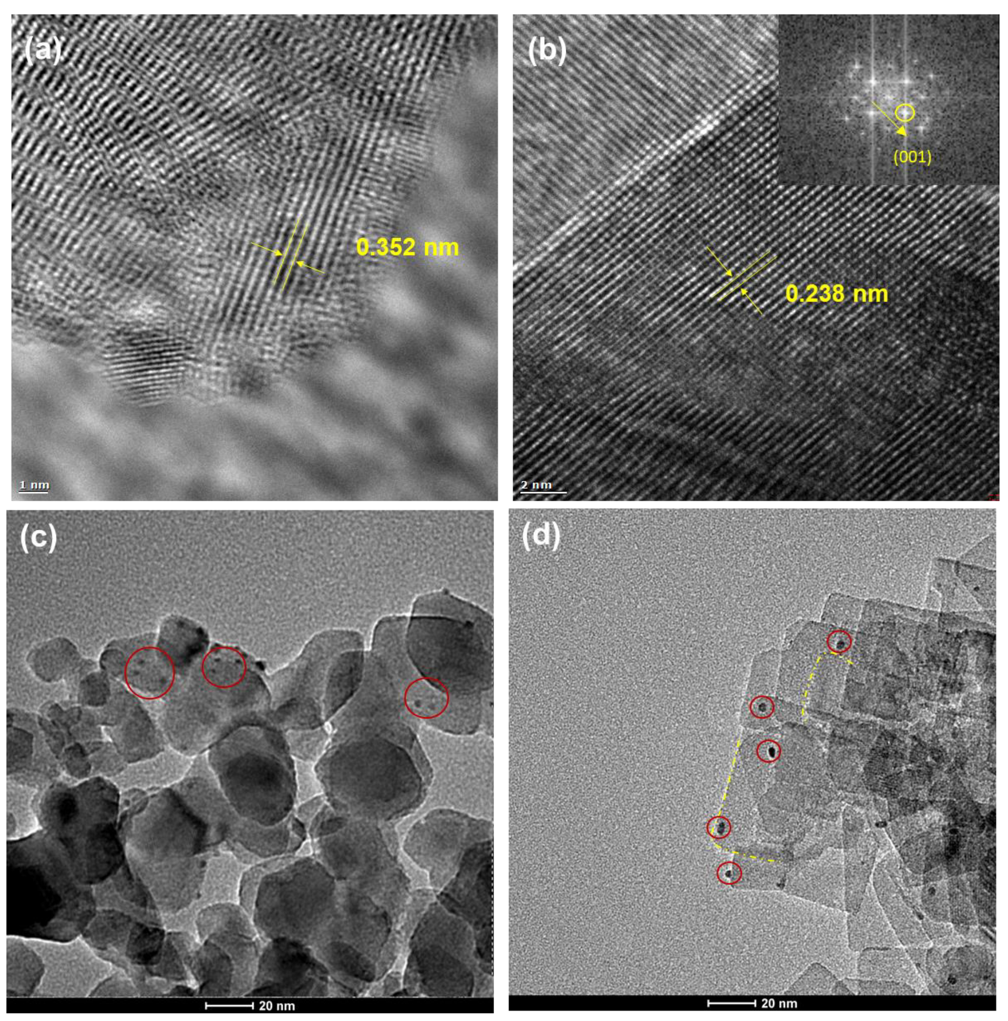
2.1. Structural Properties of Redox-Separated Photocatalysts

Facet-engineered TiO2 has a plate-like morphology with an average width of 48.30 nm and a thickness of 3.45 nm on the basis of obtained TEM images. The exposed surface of facet-engineered TiO2 is mainly composed of {001} facets, while the edge of facet-engineered TiO2 is mainly composed of {101} facets [17]. A magnified HR-TEM image of P25 shows that a lattice spacing of 0.352 nm corresponds to a (101) plane of anatase TiO2 (Figure 1a). In contrast, a magnified HR-TEM image of facet-engineered TiO2 shows a continuous lattice fringe with a spacing of 0.238 nm, corresponding to a (001) plane of anatase TiO2 (Figure 1b). This implies that the main plate of facet-engineered TiO2 is composed of {001} facets. Due to the complicated electron movements on the surface of TiO2, photodeposited Pt was positioned irregularly both in the center and on the edge of P25 (Figure 1c). The TEM image of Pt/Facet-engineered TiO2 clearly shows the presence of Pt NPs aligned on the edge of TiO2 (Figure 1d). Photoelectrons tend to move to edge of the facet-engineered TiO2; Pt deposits were selectively reduced in the edge positions. The average size of the Pt NPs of the Pt/TiO2 was estimated to be 2.7 ± 0.21 nm. As confirmed via ICP-OES, all 1.0 wt% Pt precursors used for photodeposition were loaded onto the surfaces of both the P25 and facet-engineered TiO2.
To check the Pt’s oxidation state, XPS analyses on Pt 4f were conducted on both the Pt/TiO2 and Pt/facet-engineered TiO2 (Figure 2a). The XPS clearly showed binding energies at 73.2 eV and 76.1 eV of Pt [18,19,20]. There is no significant difference of XPS between Pt/TiO2 and Pt/facet-engineered TiO2, which implies oxidation states of Pt with the two photocatalysts are the same. Figure 2b shows the XRD patterns of Pt/TiO2 and Pt/facet-engineered TiO2. The XRD pattern of the Pt/facet-engineered TiO2 is the same as that of the Pt/TiO2, which implies that the photocatalyst structure did not collapsed during either the facet-engineering or the photodeposition. The structural properties of the Pt of the two synthesized photocatalysts were the same physiochemically, only the loading position was different.

2.2. Photocatalytic Oxidation of CO

The TiO2, Pt/TiO2, and Pt/facet-engineered TiO2 films were tested for CO oxidation (Figure 3a). As a control experiment, CO oxidation was conducted without any photocatalytic films. During the 30 min of the reaction, the concentration of CO remained still. This implies CO is not oxidized by UV light irradiation without a catalytic material. The photocatalytic oxidation activities of TiO2 were negligible during the 30 min of the reaction, while that of Pt/TiO2 and Pt/facet-engineered TiO2 showed their superior activities for CO oxidation. The TiO2 with facet-engineering did not show any distinct CO oxidation. This implies Pt NPs are indispensable for CO oxidation to dissociate oxygen into active oxygen species [21]. The dissociative chemisorption of dioxygen is a prerequisite for CO oxidation, so Pt and photoelectrons are necessary for dissociation [22]. Among various noble metals such as Ag and Au, Pt-loaded TiO2 is known to exhibit superior photocatalytic oxidation efficiency for CO [10]. Without light irradiation, Pt/facet-engineered TiO2 was not activated, indicating that oxidation occurs only after photocatalytic activation. The concurrent CO2 generation was measured during CO oxidation (Figure 3b). The sum of the CO and CO2 concentrations over time was equal to the carbon inputs, meaning that the CO was converted directly to CO2 without any surface byproducts. To quantitatively compare the oxidation kinetics of CO using various photocatalysts, the pseudo first-order rate constants (for both Pt/TiO2 and Pt/facet-engineered TiO2) of CO oxidation were calculated. The pseudo first-order rate constant for CO oxidation increased approximately 2.4 times from 0.1326 ± 0.012 min−1 to 0.3212 ± 0.024 min−1 when using the Pt/facet-engineered TiO2. This implies that separating the reduction and oxidation sites significantly increases the photocatalytic CO oxidation efficiency.

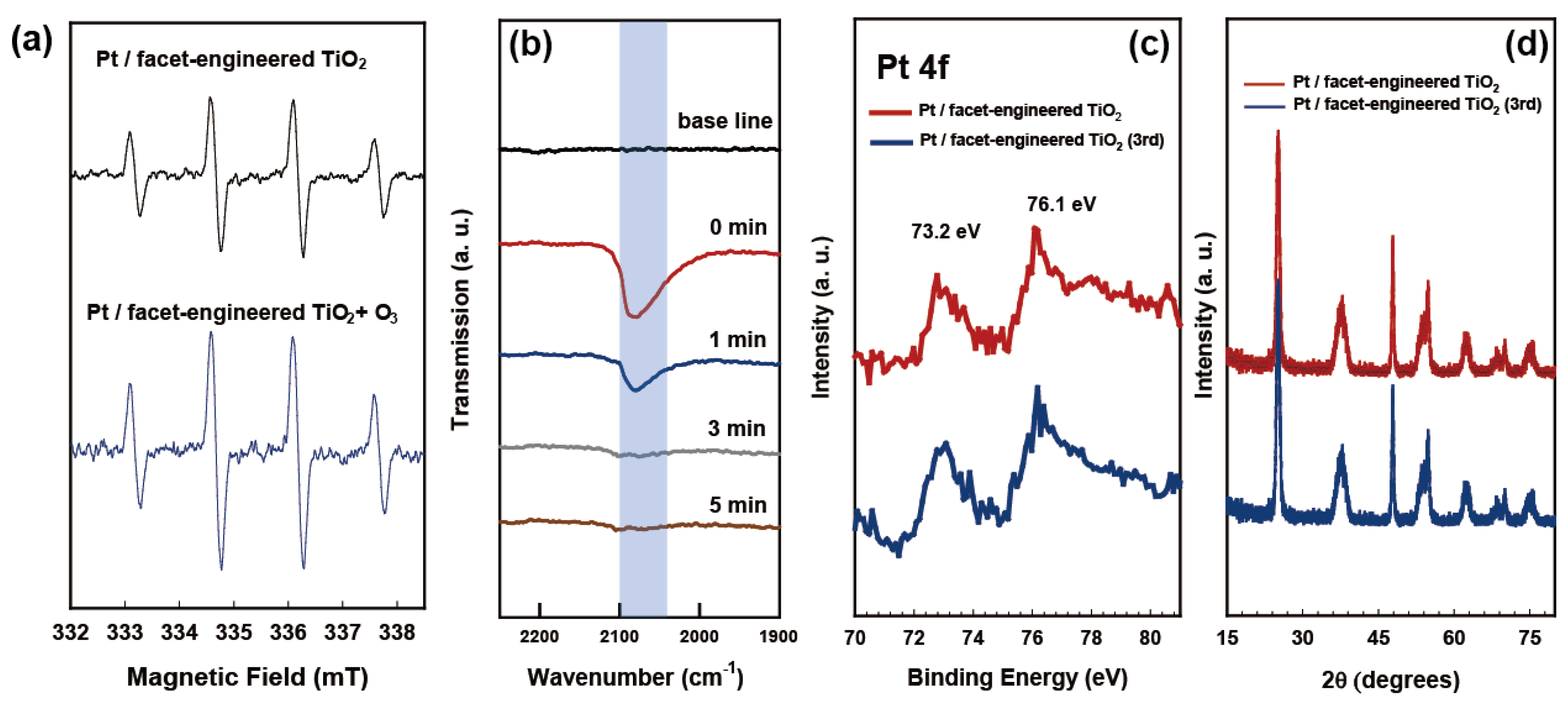
2.3. Charge Transfer Properties of Redox-Separated Photocatalyst

Electrochemical analyses of prepared photocatalysts were carried out to unveil the role of Pt NPs according to the loading locations (random site vs. reduction site). EIS experiments were performed to analyze the charge transfer resistance between the catalyst surface and the electrolyte under UV irradiation (Figure 4a). The arc in the Nyquist plot appears due to interfacial charge transfer, so the diameter of the semicircle represents the quantitative amount of the photocatalysts’ resistance. The EIS results confirm that the resistance decreased with the introduction of Pt NPs and further decreased with facet-engineering. Interestingly, once Pt was deposited onto the reduction sites of the photocatalyst, the charge separation was maximized, and the interfacial resistance was reduced. The photocurrent was measured during intermittent UV irradiation of the synthesized photocatalysts to determine the number of available photoelectrons (Figure 4b). The Pt/facet-engineered TiO2 showed a significantly enhanced photocurrent compared to Pt/TiO2 and bare TiO2. The available photoelectrons were quantitatively enhanced 2.38 times compared to the randomly deposited case once Pt was deposited on the reduction site of TiO2. This trend is consistent with the CO oxidation experiment (Figure 3a), implying that the activation of Pt is preceded by photoelectrons in the photocatalytic CO oxidation reaction.

2.4. Ozone-Assisted Photocatalytic Oxidation of CO

Ozone (O3) is another type of gaseous pollutant that humans can easily encounter indoors or in the atmosphere. O3 levels of several hundreds of ppbv are present indoors and outdoors and cause various chemical reactions [23]. When O3 is involved in photocatalytic reactions, the reaction mechanism is usually very complicated. O3 can be preferentially decomposed, preventing photocatalytic oxidation, or O3 can directly reduce air pollutants. To simulate the real-world conditions for CO oxidation, it is also necessary to determine the trend of oxidation reactions in the presence of small amounts of ozone. The CO oxidation was conducted using Pt/facet-engineered TiO2 with varying ozone concentrations (0, 51.6, 124.3, and 233.7 ppbv) (Figure 5a). The dark reaction between CO and O2 was negligible, even with the addition of O3. The ozone-enhanced CO photooxidation was observed for the Pt/facet-engineered TiO2. This implies that the electron and hole pairs generated by photon on the photocatalyst react with ozone directly or indirectly and then assist CO oxidation. Control experiments (with ozone and without a catalyst) showed no photocatalytic reaction both in dark and UV conditions. Therefore, ozonolysis of CO did not take a place, and a catalyst was essential for the ozone-enhanced effect. The ozone-induced enhancement in the photocatalytic reaction with CO was quickly saturated with an increasing concentration of ozone. The diffusion of ozone into the catalyst surface, up to 124 ppbv of ozone under UV irradiation, limited the photocatalytic rates. The role of O3 is to react with holes and facilitate the production of OH radicals and reactive oxygen species. These byproducts can directly participate in CO oxidation or can be utilized to remove surface deposits on a Pt surface. Repeated photocatalytic oxidation experiments (up to three cycles) were performed using Pt/facet-engineered TiO2 with varying ozone concentrations (Figure 5b).
It is clear that the Pt/facet-engineered TiO2 showed a gradual decrease in successive cycles of CO oxidation. The XPS and XRD signals of the Pt/facet-engineered TiO2 after the three oxidation cycles did not show any changes, demonstrating the catalyst’s structural robustness (Figure 6c–d). The reduction occurred due to the fact that Pt tends to bind strongly with CO and deactivate oxygen dissociation [24]. Once O3 was introduced to the system, the photocatalytic CO oxidation efficiency was maintained during the cycles. This implies that O3 synergistically reacts with Pt/facet-engineered TiO2, which serves to enhance both the efficiency and durability of CO oxidation.
To systematically unveil the role of O3 and Pt/facet-engineered TiO2, EPR and in situ DRIFTs were conducted on Pt/facet-engineered TiO2 with O3 exposure. EPR spin-trapping was used to verify the OH radical production of each catalyst system. After 15 min of irradiation, OH radicals were detected in the Pt/facet-engineered TiO2 (Figure 6a). Once O3 was introduced into the Pt/facet-engineered TiO2 along with the light irradiation, the OH radical signal was significantly enhanced. This implies that photogenerated holes can react with ozone and thereby produce more OH radicals. The in situ DRIFTS was taken using used Pt/facet-engineered TiO2 after three successive oxidation cycles which simulated poisoning with CO adsorption (Figure 6b). A broad peak containing linear CO on Pt NPs (2050–2080 cm−1) and Ptδ+-CO (2100 cm−1) was found [25]. After the ozone exposure, the broad peak gradually decreased over time, and the CO could be desorbed on the Pt surface. The poisoned Pt surface of Pt/facet-engineered TiO2 was regenerated upon the ozone exposure. The role of the Pt/facet-engineered TiO2 and O3 is schematically illustrated in Scheme 1. In general, Pt/TiO2 has mixed redox centers therefore, there are a lot of recombination of charge carriers, which significantly reduces photocatalytic activity. Facet-engineering with Pt loading can successfully divide reduction and oxidation centers. Therefore, CO can be efficiently oxidized at the Pt center that holds the photogenerated electrons. On the other hand, the remaining oxidation centers can react with various gaseous pollutants. In particular, O3 can react with a hole to produce an OH radical. The produced OH radical can sustainably regenerate the Pt poisoned surface, which is a major limitation for ambient catalytic CO oxidation. The material design that separates the redox center is a good strategy that shows synergy by simultaneously performing CO oxidation and O3 decomposition.

3. Experimental Section

3.1. Chemicals

All chemicals for material synthesis and analyses were used as received without any purification. Titanium butoxide (≥97.0%), ethanol (≥99.5%), sodium hydroxide (NaOH), hydrogen fluoride (HF), chloroplatinic acid hydrate (H2PtCl6), and methanol (HPLC grade, >99.9%) were purchased from Sigma Aldrich (St. Louis, MO, USA). Commercial TiO2 (P25) was purchased from Evonik (Essen, Germany). All aqueous solutions were prepared with ultrapure/deionized water (DI water, ≥18.2 MΩ·cm) from a Milli-Q system.

3.2. Preparation of Redox-Separated Photocatalysts

Facet-engineered TiO2 was prepared via a hydrothermal method [26]. A mixed solution of HF (3 mL) and titanium butoxide (25 mL) was poured into a 100 mL Teflon autoclave and heated for 24 h at 200 °C. The precipitate formed was separated using a centrifugation, washed with DI water, and then dried at oven (60 °C) for 12 h to yield a white powder. The loading of Pt on the reductive sites of the facet-engineered TiO2 was achieved by dispersing 0.1 g facet-engineered TiO2 with 320 μL H2PtCl6 (10 mM), which was added to the suspension. The mixture was stirred vigorously for 1 h at 1000 rpm. The suspension was subsequently irradiated with a 200 W mercury lamp for the photodeposition of Pt NP. The resulting material was collected via centrifugation, washed with DI water, and dried overnight at 60 °C to yield Pt/facet-engineered TiO2. As a comparison group, a commercial TiO2, P25, was used once for Pt deposition; this was named Pt/TiO2. For CO oxidation and electrochemical analyses, the photocatalysts were fixed and coated onto substrates. The synthesized catalysts were thoroughly mixed with ethanol to produce a homogeneous paste (0.15 g/mL), which was doctor-bladed onto a indium tin oxide (ITO) substrate of the size of 2 cm × 2 cm [27]. The resulting film used for the analyses were dried at 200 °C by flowing N2 for 2 h to remove residual ethanol.

3.3. CO Oxidation Measurements

The carbon monoxide (CO) oxidation was conducted at ambient conditions (room temperature and atmospheric pressure) in a closed-circulation reactor [27]. A Pyrex glass reactor (volume: 300 mL) with a quartz window (radius: 30 mm) was connected to photoacoustic gas monitor (INNOVA 1412i, LumaSense, Santa Clara, CA, USA) using a Teflon tube (radius: 2 mm). A magnetic bar was placed inside the reactor to circulate the air in it. A 370 nm-emitting UV-LED (ICN14D-096, Luna Fiber Optic Korea, Seul, Republic of Korea) was used as a light source to activate the photocatalysts. The intensity of the UV light flux at the surface of the photocatalyst was measured to be 16 mW/cm2 using a power meter (1815-C, Newport, Irvine, CA, USA). The photoacoustic gas monitor can measure the concentrations of CO, carbon dioxide (CO2), and water vapor simultaneously. The concentration of CO was adjusted by diluting standard gas (1000 ppmv CO in N2 as a carrier gas). The relative humidity was controlled atcirca 65 ± 10% by bubbling synthetic air through a stainless steel bottle containing DI water. O3 was introduced through the ozone generator (Evoqua) connected to the glass reactor. O3 was produced from the flow of oxygen standard gas (99.9%). The maximum production rate of O3 into the reactor was 1.6 g/min. The photocatalyst films of Pt/Facet-engineered TiO2, Pt/TiO2, and TiO2 were compared for CO oxidation under the same conditions. Before each experiment, the reactor was flushed with air to remove any remaining gases.

3.4. In Situ Diffuse Reflectance Infrared Fourier Transform Spectroscopy (In Situ DRIFTS)

In situ DRIFTS was performed using a FT-IR spectrometer (PerkinElmer, Waltham, MA, USA) equipped with a diffuse-reflectance cell (PIKE Technologies, Cottonwood, AZ, USA) with a ZnSe window. Powder catalysts were placed in the cell. CO of 100 ppmv was introduced into the cell by diluting the standard gas (300 ppmv CO in N2) with air. The relative humidity was adjusted by bubbling air through a stainless-steel bottle containing DI water. The in situ DRIFTS were collected after exposing the used sample (up to three successive CO oxidation cycles) to the flowing O3 stream to irradiation for 1 min, 3 min, and 5 min, respectively.

3.5. Material Characterizations

The high-resolution transmission electron microscopy (HR-TEM) images were taken using a JEM-2200FS (JEOL) operated at 200 kV, coupled with Cs correction. X-ray photoelectron spectroscopy (XPS) measurements were conducted using a Versa Probe Ⅱ Scanning XPS Microprobe (Physical Electronics (PHI)). X-ray diffraction (XRD) spectra were obtained using Cu-Kα radiation XRD (Mac Science Co., M18XHF, Tokyo, Japan). Electron paramagnetic resonance (EPR) measurements were analyzed using a JES-X310 spectrometer (JEOL, Tokyo, Japan). The Pt loading amount was measured using inductively coupled plasma optical emission spectrometry (ICP-OES-6300-Thermo Scientific, Waltham, MA, USA).

3.6. Photoelectrochemical Measurements

Photoelectrochemical (PEC) analyses were conducted using a potentiostat (Gamry, Warminster, PA, USA, Reference 600) connecting a three-electrode system. The prepared photocatalyst film, a Ag/AgCl electrode and Pt foil, were employed as a working, reference and a counter electrode, respectively. The electrochemical impedance spectroscopy (EIS) Nyquist plot was obtained using an alternating current (AC) voltage of 30 mV. PEC measurements were carried out with a potential of +0.5 V in the solution of 0.1 M NaClO4.

4. Conclusions

To boost the photocatalytic activity in material design, separating reduction and oxidation sites is an efficient method. Since the electronic structures and surface reactivity are different depending on crystal facets, facet-engineering can be used for separating oxidation and reduction sites [28]. Band alignment between different facets provides a route for charge carriers to separate. The {111} and {110} facets of rutile TiO2 are regarded as the oxidation and reduction facets, respectively [29,30]. As a major visible-light photocatalyst, four predominant exposed facets of BiVO4 and charge transfer properties have also been elucidated [31]. In addition, the simultaneous embedding of dual cocatalysts onto photocatalysts has been investigated with the aim of separating redox centers and enhancing photocatalytic activities [32]. Recently, oxidative and reductive cocatalysts were loaded onto 2D C3N4 to achieve facile water oxidation and H2O2 production. Cobalt single atoms were loaded onto oxidative sites for improving water oxidation efficiency, whereas anthraquinone was deposited onto reductive sites for enhancing photoreduction efficiency [15]. Here, I synthesized selectively loaded Pt on the reduction site of facet-engineered TiO2 and applied it to CO oxidation at room temperature. The CO was efficiently oxidized with enhanced oxygen dissociation, which occurs via photoelectrons transferred to Pt. Spatially separated Pt can efficiently draw electrons and utilize them for CO oxidation. The remaining holes can be utilized for ozone decomposition. Ozone was decomposed into OH radical, which can reactivate a Pt surface poisoned with CO. In general, CO oxidation using nanomaterials has a property whereby the efficiency gradually decreases under ambient conditions. This is because CO has a high affinity for Pt and covers the surface. The redox-separated photocatalyst capable of maximizing charge separation efficiency can oxidize CO while decomposing O3 via oxidative pathways. The Pt/facet-engineered TiO2 can serve as versatile platform that synergizes to oxidize CO and decompose O3, simultaneously.

Funding

This study was funded by the Korea University (Grant No. K2008841) and the Ministry of Environment as “The Graduate School of Particulate Matter Specialization”.

Institutional Review Board Statement

Not applicable.

Informed Consent Statement

Not applicable.

Data Availability Statement

Not applicable.

Conflicts of Interest

The author declares no conflict of interest.

References

  1. Rose, J.J.; Wang, L.; Xu, Q.; McTiernan, C.F.; Shiva, S.; Tejero, J.; Gladwin, M.T. Carbon monoxide poisoning: Pathogenesis, management, and future directions of therapy. Am. J. Respir. Crit. Care Med. 2017, 195, 596–606. [Google Scholar] [CrossRef] [PubMed] [Green Version]
  2. Raub, J.A.; Mathieu-Nolf, M.; Hampson, N.B.; Thom, S.R. Carbon monoxide poisoning—A public health perspective. Toxicology 2000, 145, 1–14. [Google Scholar] [CrossRef] [PubMed]
  3. Spengler, J.D.; Sexton, K. Indoor air pollution: A public health perspective. Science 1983, 221, 9–17. [Google Scholar] [CrossRef] [PubMed]
  4. Ma, J.; Li, L.; Ren, J.; Li, R. CO adsorption on activated carbon-supported Cu-based adsorbent prepared by a facile route. Sep. Purif. Technol. 2010, 76, 89–93. [Google Scholar] [CrossRef]
  5. Yin, Y.; Wen, Z.; Shi, L.; Zhang, Z.; Yang, Z.; Xu, C.; Sun, H.; Wang, S.; Yuan, A. Cuprous/vanadium sites on MIL-101 for selective CO adsorption from gas mixtures with superior stability. ACS Sustain. Chem. Eng. 2019, 7, 11284–11292. [Google Scholar] [CrossRef]
  6. Heiz, U.; Sanchez, A.; Abbet, S.; Schneider, W.-D. Catalytic oxidation of carbon monoxide on monodispersed platinum clusters: Each atom counts. J. Am. Chem. Soc. 1999, 121, 3214–3217. [Google Scholar] [CrossRef]
  7. Zhou, Y.; Wang, Z.; Liu, C. Perspective on CO oxidation over Pd-based catalysts. Catal. Sci. Technol. 2015, 5, 69–81. [Google Scholar] [CrossRef]
  8. Gatla, S.; Aubert, D.; Agostini, G.; Mathon, O.; Pascarelli, S.; Lunkenbein, T.; Willinger, M.G.; Kaper, H. Room-Temperature CO Oxidation Catalyst: Low-Temperature Metal–Support Interaction between Platinum Nanoparticles and Nanosized Ceria. ACS Catal. 2016, 6, 6151–6155. [Google Scholar] [CrossRef]
  9. Deng, X.-Q.; Zhu, B.; Li, X.-S.; Liu, J.-L.; Zhu, X.; Zhu, A.-M. Visible-light photocatalytic oxidation of CO over plasmonic Au/TiO2: Unusual features of oxygen plasma activation. Appl. Catal. B: Environ. 2016, 188, 48–55. [Google Scholar] [CrossRef]
  10. Kolobov, N.; Svintsitskiy, D.; Kozlova, E.; Selishchev, D.; Kozlov, D. UV-LED photocatalytic oxidation of carbon monoxide over TiO2 supported with noble metal nanoparticles. Chem. Eng. J. 2017, 314, 600–611. [Google Scholar] [CrossRef]
  11. Zhang, T.; Wang, S.; Chen, F. Pt–Ru Bimetal Alloy Loaded TiO2 Photocatalyst and Its Enhanced Photocatalytic Performance for CO Oxidation. J. Phys. Chem. C 2016, 120, 9732–9739. [Google Scholar]
  12. Hwang, S.; Lee, M.C.; Choi, W. Highly enhanced photocatalytic oxidation of CO on titania deposited with Pt nanoparticles: Kinetics and mechanism. Appl. Catal. B Environ. 2003, 46, 49–63. [Google Scholar] [CrossRef]
  13. Weon, S.; He, F.; Choi, W. Status and challenges in photocatalytic nanotechnology for cleaning air polluted with volatile organic compounds: Visible light utilization and catalyst deactivation. Environ. Sci. Nano 2019, 6, 3185–3214. [Google Scholar] [CrossRef]
  14. Weon, S.; Choi, E.; Kim, H.; Kim, J.Y.; Park, H.-J.; Kim, S.-m.; Kim, W.; Choi, W. Active {001} Facet Exposed TiO2 Nanotubes Photocatalyst Filter for Volatile Organic Compounds Removal: From Material Development to Commercial Indoor Air Cleaner Application. Environ. Sci. Technol. 2018, 52, 9330–9340. [Google Scholar]
  15. Chu, C.; Zhu, Q.; Pan, Z.; Gupta, S.; Huang, D.; Du, Y.; Weon, S.; Wu, Y.; Muhich, C.; Stavitski, E.; et al. Spatially separating redox centers on 2D carbon nitride with cobalt single atom for photocatalytic H2O2 production. Proc. Natl. Acad. Sci. USA 2020, 117, 6376–6382. [Google Scholar] [CrossRef] [Green Version]
  16. Ong, W.-J.; Tan, L.-L.; Chai, S.-P.; Yong, S.-T.; Mohamed, A.R. Highly reactive {001} facets of TiO2-based composites: Synthesis, formation mechanism and characterization. Nanoscale 2014, 6, 1946–2008. [Google Scholar] [CrossRef]
  17. Xiong, Z.; Lei, Z.; Li, Y.; Dong, L.; Zhao, Y.; Zhang, J. A review on modification of facet-engineered TiO2 for photocatalytic CO2 reduction. J. Photochem. Photobiol. C Photochem. Rev. 2018, 36, 24–47. [Google Scholar]
  18. Ono, L.K.; Yuan, B.; Heinrich, H.; Cuenya, B.R. Formation and Thermal Stability of Platinum Oxides on Size-Selected Platinum Nanoparticles: Support Effects. J. Phys. Chem. C 2010, 114, 22119–22133. [Google Scholar] [CrossRef]
  19. Svintsitskiy, D.A.; Kibis, L.S.; Stadnichenko, A.I.; Koscheev, S.V.; Zaikovskii, V.I.; Boronin, A.I. Highly Oxidized Platinum Nanoparticles Prepared through Radio-Frequency Sputtering: Thermal Stability and Reaction Probability towards CO. ChemPhysChem 2015, 16, 3318–3324. [Google Scholar]
  20. Weon, S.; Kim, J.; Choi, W. Dual-components modified TiO2 with Pt and fluoride as deactivation-resistant photocatalyst for the degradation of volatile organic compound. Appl. Catal. B Environ. 2018, 220, 1–8. [Google Scholar] [CrossRef]
  21. Gambardella, P.; Šljivančanin, Ž.; Hammer, B.; Blanc, M.; Kuhnke, K.; Kern, K. Oxygen dissociation at Pt steps. Phys. Rev. Lett. 2001, 87, 056103. [Google Scholar] [CrossRef] [PubMed]
  22. Li, Q.; Wang, K.; Zhang, S.; Zhang, M.; Yang, J.; Jin, Z. Effect of photocatalytic activity of CO oxidation on Pt/TiO2 by strong interaction between Pt and TiO2 under oxidizing atmosphere. J. Mol. Catal. A Chem. 2006, 258, 83–88. [Google Scholar] [CrossRef]
  23. Weschler, C.J. Ozone in indoor environments: Concentration and chemistry. Indoor Air 2000, 10, 269–288. [Google Scholar] [CrossRef] [PubMed] [Green Version]
  24. Chen, W.; Cao, J.; Fu, W.; Zhang, J.; Qian, G.; Yang, J.; Chen, D.; Zhou, X.; Yuan, W.; Duan, X. Molecular-Level Insights into the Notorious CO Poisoning of Platinum Catalyst. Angew. Chem. Int. Ed. 2022, 61. [Google Scholar] [CrossRef]
  25. Ding, K.; Gulec, A.; Johnson, A.M.; Schweitzer, N.M.; Stucky, G.D.; Marks, L.D.; Stair, P.C. Identification of active sites in CO oxidation and water-gas shift over supported Pt catalysts. Science 2015, 350, 189–192. [Google Scholar] [CrossRef] [Green Version]
  26. Weon, S.; Suh, M.-J.; Chu, C.; Huang, D.; Stavitski, E.; Kim, J.-H. Site-Selective Loading of Single-Atom Pt on TiO2 for Photocatalytic Oxidation and Reductive Hydrodefluorination. ACS EST Eng. 2021, 1, 512–522. [Google Scholar] [CrossRef]
  27. Weon, S.; Choi, W. TiO2 Nanotubes with Open Channels as Deactivation-Resistant Photocatalyst for the Degradation of Volatile Organic Compounds. Environ. Sci. Technol. 2016, 50, 2556–2563. [Google Scholar] [CrossRef]
  28. Lee, M.G.; Yang, J.W.; Kwon, H.R.; Jang, H.W. Crystal facet and phase engineering for advanced water splitting. CrystEngComm 2022, 24, 5838–5864. [Google Scholar] [CrossRef]
  29. Zhang, Q.; Li, R.; Li, Z.; Li, A.; Wang, S.; Liang, Z.; Liao, S.; Li, C. The dependence of photocatalytic activity on the selective and nonselective deposition of noble metal cocatalysts on the facets of rutile TiO2. J. Catal. 2016, 337, 36–44. [Google Scholar] [CrossRef]
  30. Liu, G.; Yang, H.G.; Pan, J.; Yang, Y.Q.; Lu, G.Q.; Cheng, H.-M. Titanium Dioxide Crystals with Tailored Facets. Chem. Rev. 2014, 114, 9559–9612. [Google Scholar] [CrossRef]
  31. Lardhi, S.; Cavallo, L.; Harb, M. Significant Impact of Exposed Facets on the BiVO4 Material Performance for Photocatalytic Water Splitting Reactions. J. Phys. Chem. Lett. 2020, 11, 5497–5503. [Google Scholar] [CrossRef] [PubMed]
  32. Qiu, B.; Du, M.; Ma, Y.; Zhu, Q.; Xing, M.; Zhang, J. Integration of redox cocatalysts for artificial photosynthesis. Energy Environ. Sci. 2021, 14, 5260–5288. [Google Scholar] [CrossRef]
Figure 1. Magnified HR-TEM images obtained from (a) TiO2 and (b) facet-engineered TiO2. The inset of (b) shows the FFT (Fast Fourier Transform) pattern of facet-engineered TiO2. HR-TEM images obtained from (c) Pt/TiO2 and (d) Pt/facet-engineered TiO2. The concentration of Pt of each photocatalyst was fixed at 1.0 wt% with respect to TiO2 on a weight basis. Red circles represent Pt nanoparticles loaded onto TiO2. Yellow lines represent the edge of facet-engineered TiO2.
Molecules 27 08482 g001
Figure 2. (a) XPS spectra and (b) XRD pattern of Pt 4f of Pt/TiO2 and Pt/facet-engineered TiO2.
Molecules 27 08482 g002
Figure 3. Time-dependent profiles of (a) photocatalytic oxidation of CO and (b) the concurrent production of CO2 on TiO2, facet-engineered TiO2, Pt/TiO2, Pt/facet-engineered TiO2, and control experiments (with/without photocatalyst film or irradiation). Experimental conditions: catalyst film size = 2 × 2 cm2, light source = UV LED (370 nm), and [CO]0 = 50 ppmv. Each oxidation experiment consisted of 10 min for adsorption equilibrium (dark) and 30 min for UV irradiation.
Molecules 27 08482 g003
Figure 4. (a) Nyquist plots of prepared photocatalysts coated onto ITO from 1 MHz to 0.01 Hz at 0.5 V under UV irradiation. (b) Photocurrent production of prepared photocatalysts coated onto ITO under UV irradiation (60–90 s, 120–150 s, and 180–210 s).
Molecules 27 08482 g004
Figure 5. (a) Time-dependent profiles of photocatalytic oxidation of CO on Pt/facet-engineered TiO2 in several different initial ozone concentrations. (b) Repeated photocatalytic oxidation cycles of CO on Pt/facet-engineered TiO2 in several different initial ozone concentrations.
Molecules 27 08482 g005
Figure 6. (a) Spin trap EPR of Pt/facet-engineered TiO2 with/without exposure to O3. Experimental conditions: light source = UV LED; illumination time: 15 min; catalyst dose = 0.25 g/L; [DMPO]0 = 30 mM; [O3] = 124.3 ppbv. (b) In situ Diffuse Reflectance Infrared Fourier Transform Spectroscopy DRIFTS (In situ DRIFTS) for Pt/facet-engineered TiO2 after three successive cycles of photocatalytic oxidation of CO. After exposing the sample to ozone flow with air for 1 min, 3 min, and 5 min. (c) XPS spectra and (d) XRD pattern of Pt 4f of Pt/facet-engineered TiO2, after 3rd photocatalysis cycle.
Molecules 27 08482 g006
Scheme 1. Schematic illustrations of (1) photocatalytic oxidation of CO using Pt/TiO2 and (2) site—selective removal of CO and O3 on Pt/facet-engineered TiO2.
Molecules 27 08482 sch001
Publisher’s Note: MDPI stays neutral with regard to jurisdictional claims in published maps and institutional affiliations.

