
Solid Oxide Cells with Phase-Inversion Tape-Casted Hydrogen Electrode and SrSc0.175Nb0.025Co0.8O3−δ Oxygen Electrode for High-Performance Reversible Power Generation and Hydrogen Production


 ,
, 
Abstract
1. Introduction
2. Results and Discussion
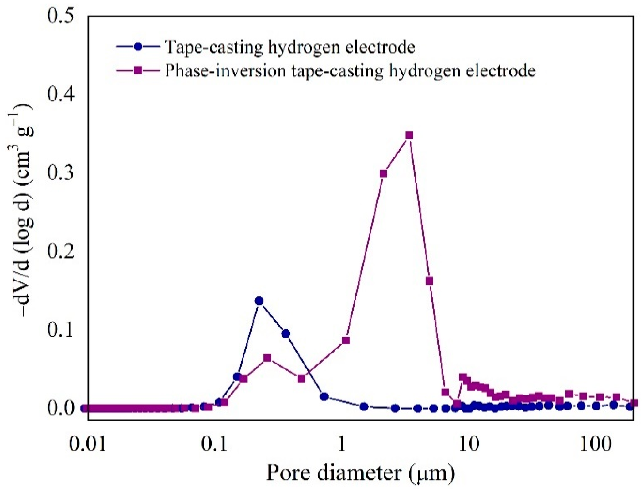
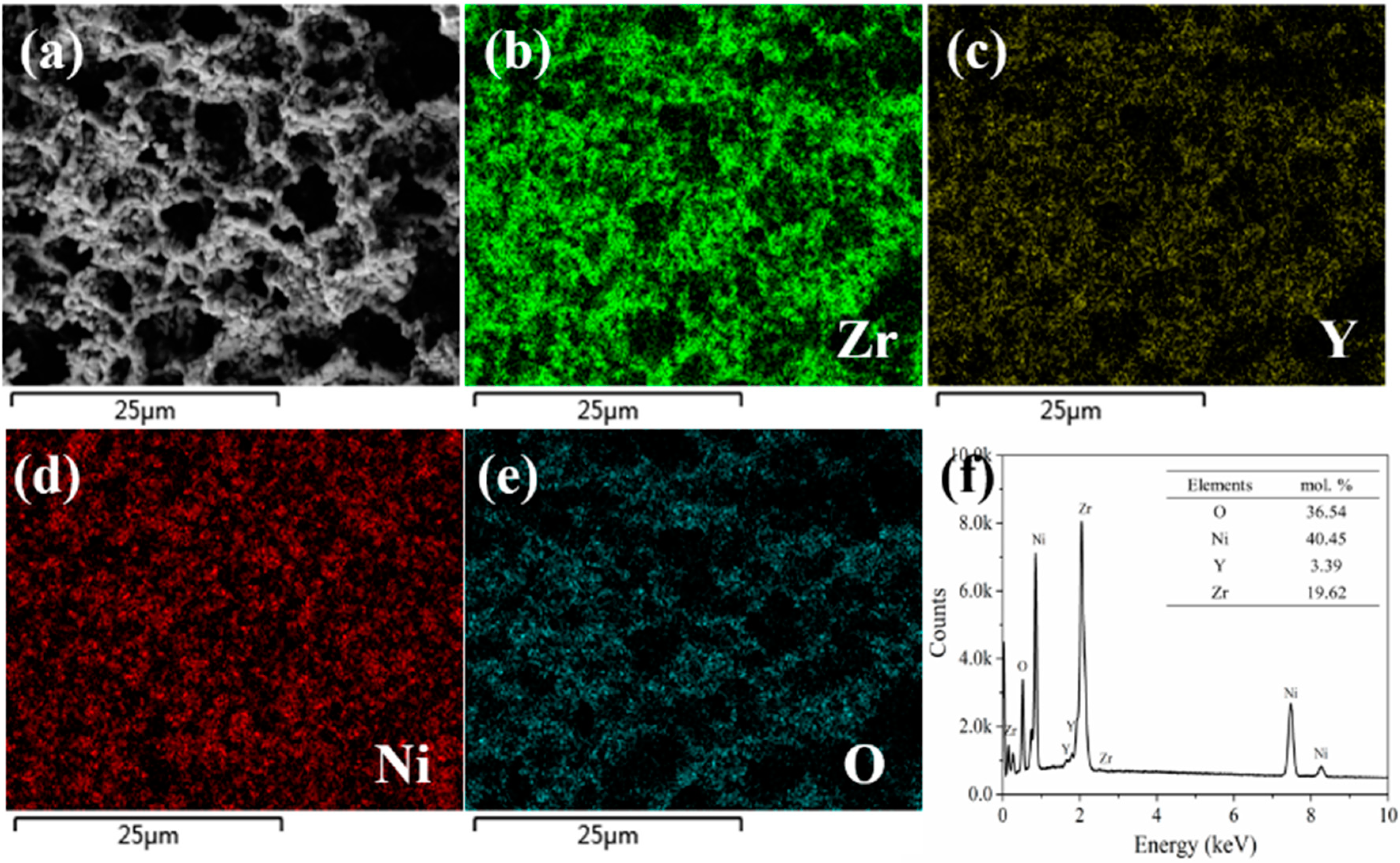
2.1. Microstructure of Hydrogen Electrode
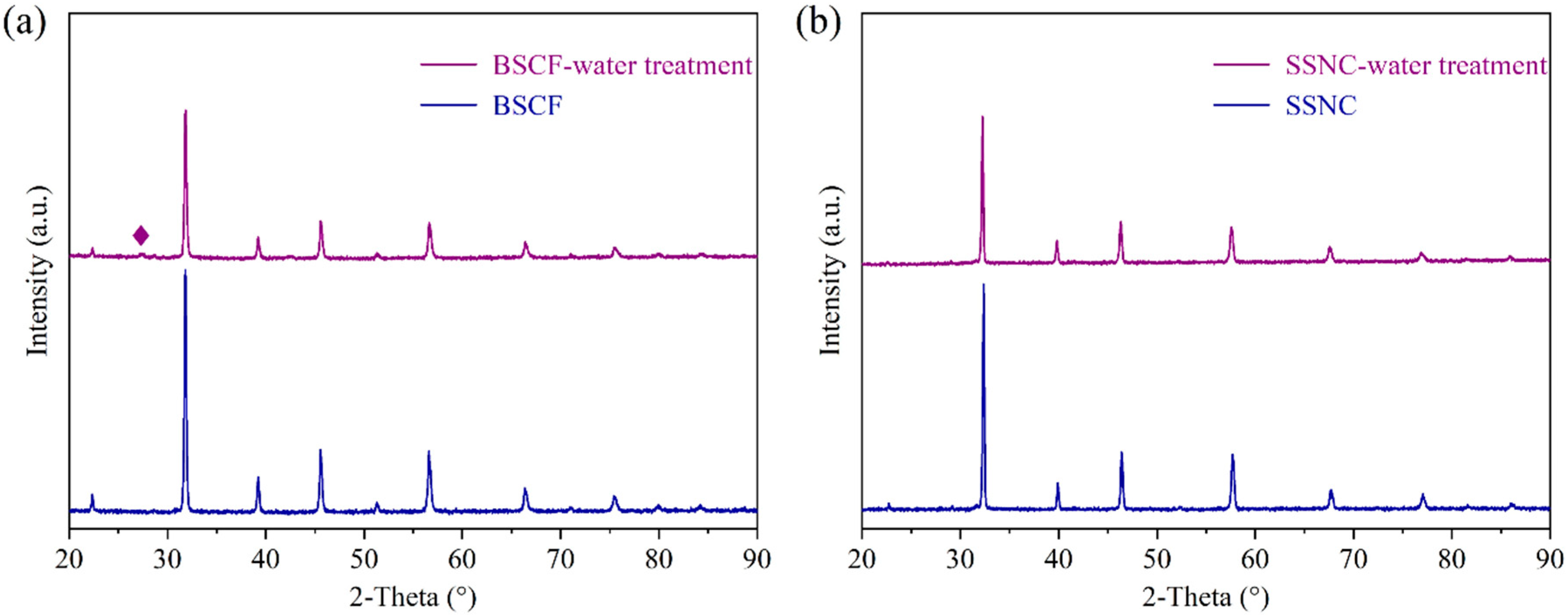
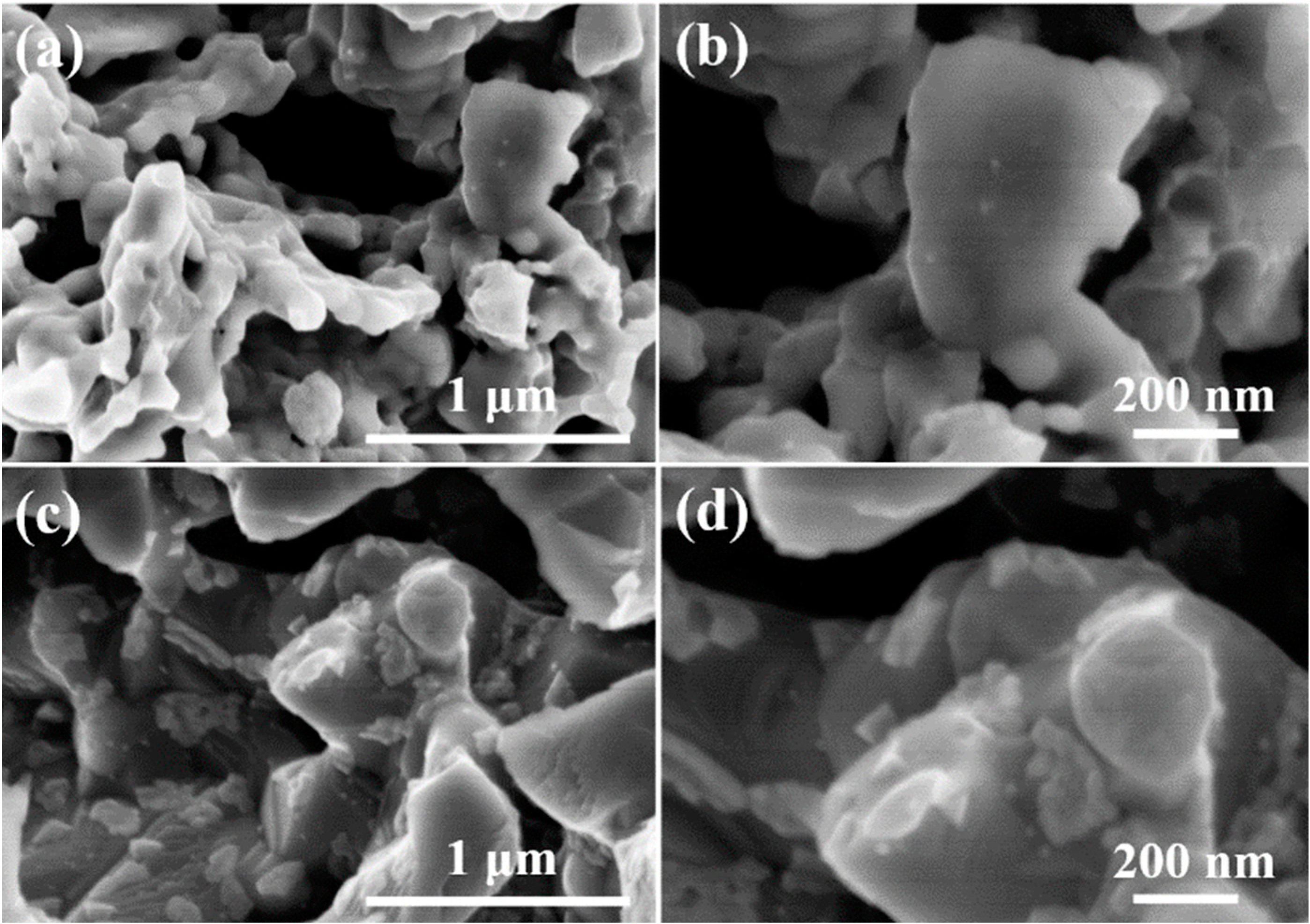
2.2. Water Resistance of Oxygen Electrode
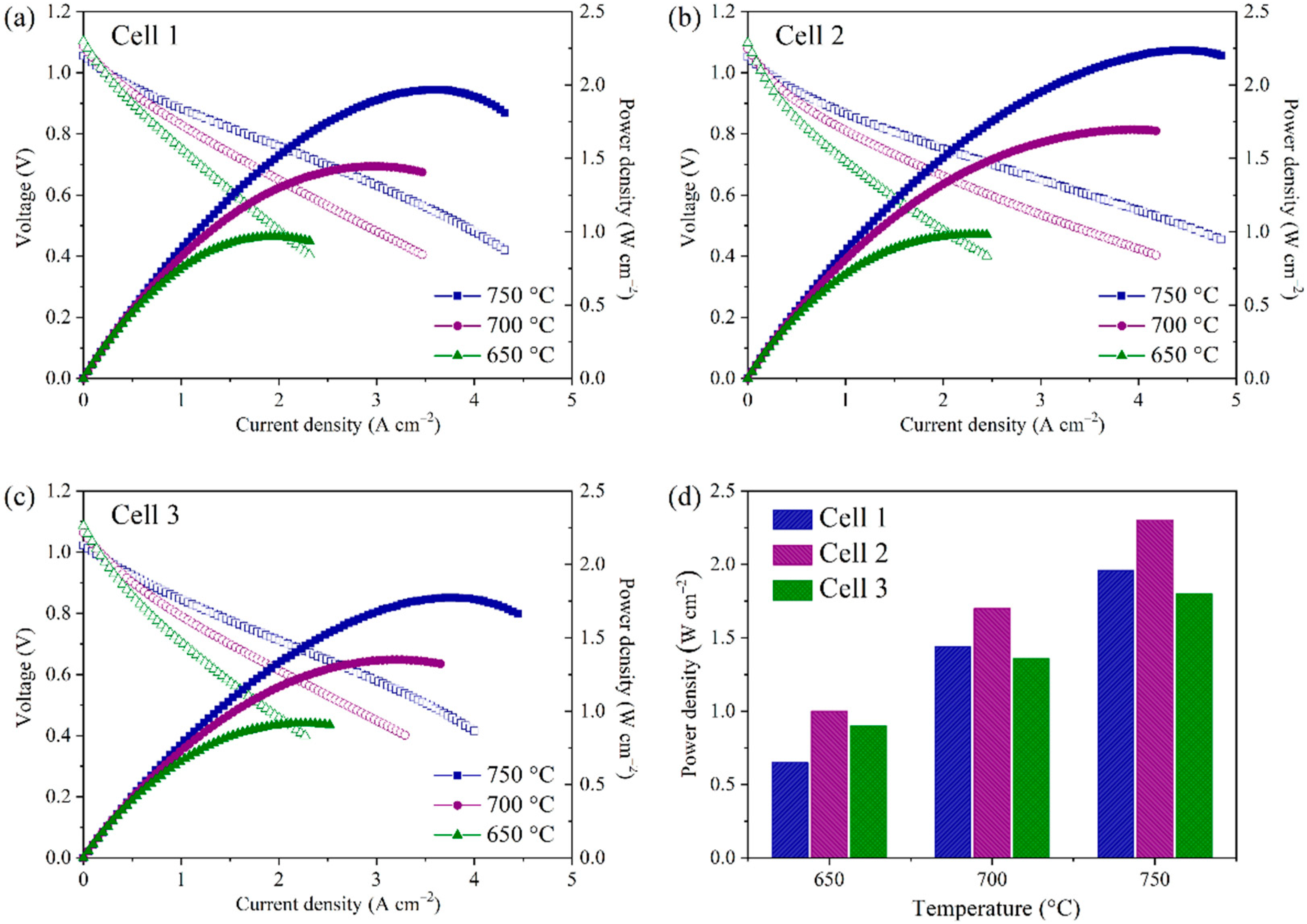
2.3. SOFC Mode
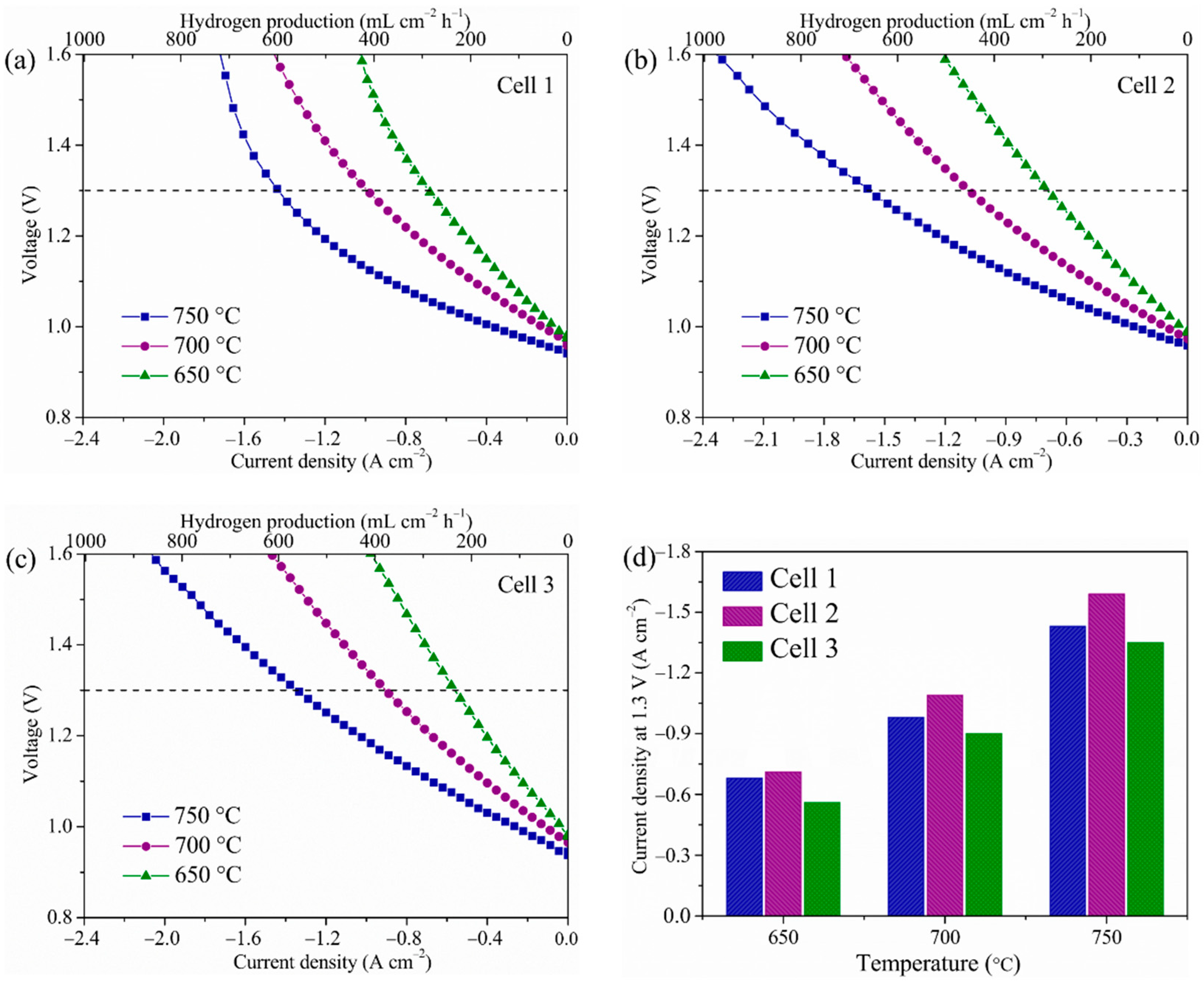
2.4. SOEC Mode
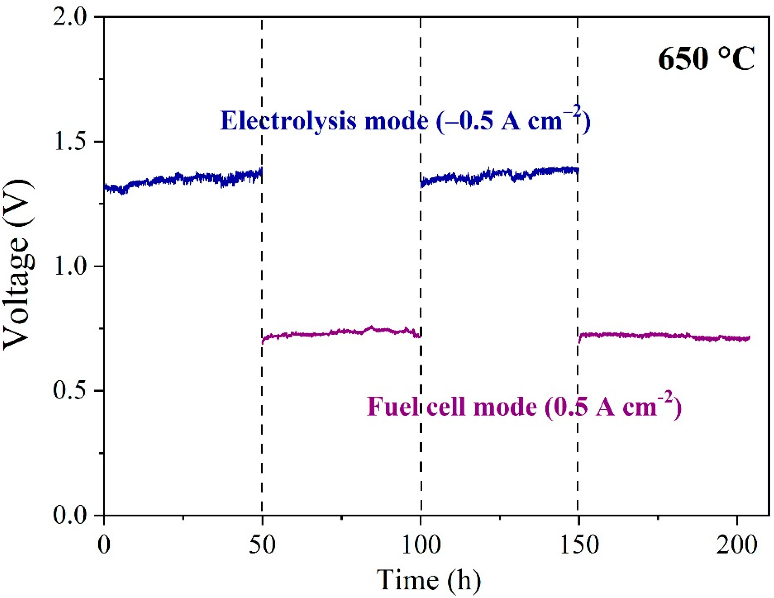
2.5. Stability
3. Materials and Methods
3.1. Powder Preparation
3.2. Single Cell Preparation
3.3. Characterization and Measurements
4. Conclusions
Supplementary Materials
Author Contributions
Funding
Institutional Review Board Statement
Informed Consent Statement
Data Availability Statement
Conflicts of Interest
Sample Availability
References
- Li, C.; Zhu, D.; Cheng, S.; Zuo, Y.; Wang, Y.; Ma, C.; Dong, H. Recent research progress of bimetallic phosphides-based nanomaterials as cocatalyst for photocatalytic hydrogen evolution. Chin. Chem. Lett. 2022, 33, 1141–1153. [Google Scholar] [CrossRef]
- Yang, M.; He, F.; Zhou, C.; Dong, F.; Yang, G.; Zhou, W.; Shao, Z. New perovskite membrane with improved sintering and self-reconstructed surface for efficient hydrogen permeation. J. Membr. Sci. 2021, 620, 118980. [Google Scholar] [CrossRef]
- Parra, D.; Valverde, L.; Pino, F.J.; Patela, M.K. A review on the role, cost and value of hydrogen energy systems for deep decarbonisation. Renew. Sustain. Energy Rev. 2019, 101, 279–294. [Google Scholar] [CrossRef]
- Liu, Z.; Chen, Y.; Yang, G.; Yang, M.; Ji, R.; Song, Y.; Ran, R.; Zhou, W.; Shao, Z. One-pot derived thermodynamically quasi-stable triple conducting nanocomposite as robust bifunctional air electrode for reversible protonic ceramic cells. Appl. Catal. B Environ. 2022, 319, 121929. [Google Scholar] [CrossRef]
- Bi, L.; Boulfrad, S.; Traversa, E. Steam electrolysis by solid oxide electrolysis cells (SOECs) with proton-conducting oxides. Chem. Soc. Rev. 2014, 43, 8255–8270. [Google Scholar] [CrossRef]
- Lei, L.; Zhang, J.; Yuan, Z.; Liu, J.; Ni, M.; Chen, F. Progress report on proton conducting solid oxide electrolysis cells. Adv. Funct. Mater. 2019, 29, 1903805. [Google Scholar] [CrossRef]
- Kim, S.; Kim, G.; Manthiram, A. Dysprosium doping effects on perovskite oxides for air and fuel electrodes of solid oxide cells. J. Power Sources 2021, 497, 229873. [Google Scholar] [CrossRef]
- Liu, Z.; Cheng, D.; Zhu, Y.; Liang, M.; Yang, M.; Yang, G.; Ran, R.; Wang, W.; Zhou, W.; Shao, Z. Robust bifunctional phosphorus-doped perovskite oxygen electrode for reversible proton ceramic electrochemical cells. Chem. Eng. J. 2022, 450, 137787. [Google Scholar] [CrossRef]
- Zhang, W.; Zhou, Y.; Liu, E.; Ding, Y.; Luo, Z.; Li, T.; Kane, N.; Zhao, B.; Niu, Y.; Liu, Y.; et al. A highly efficient and durable air electrode for intermediate-temperature reversible solid oxide cells. Appl. Catal. B Environ. 2021, 299, 120631. [Google Scholar] [CrossRef]
- Liu, Y.; Shao, Z.; Mori, T. Development of nickel based cermet anode materials in solid oxide fuel cells–Now and future. Mater. Rep. Energy 2021, 1, 100003. [Google Scholar] [CrossRef]
- Yang, G.; Su, C.; Shi, H.; Zhu, Y.; Song, Y.; Zhou, W.; Shao, Z. Toward reducing the operation temperature of solid oxide fuel cells: Our past 15 years of efforts in cathode development. Energy Fuels 2020, 34, 15169–15194. [Google Scholar] [CrossRef]
- Xu, X.; Su, C.; Shao, Z. Fundamental understanding and application of Ba0.5Sr0.5Co0.8Fe0.2O3−δ perovskite in energy storage and conversion: Past, present, and future. Energy Fuels 2021, 35, 13585–13609. [Google Scholar] [CrossRef]
- Liang, M.; Zhu, Y.; Song, Y.; Guan, D.; Luo, Z.; Yang, G.; Jiang, S.P.; Zhou, W.; Ran, R.; Shao, Z. A new durable surface nanoparticles-modified perovskite cathode for protonic ceramic fuel cells from selective cation exsolution under oxidizing atmosphere. Adv. Mater. 2021, 34, 2106379. [Google Scholar] [CrossRef]
- Yang, T.; Kollasch, S.L.; Grimes, J.; Xue, A.; Barnett, S.A. (La0.8Sr0.2)0.98MnO3−δ-Zr0.92Y0.16O2−δ: PrOx for oxygen electrode supported solid oxide cells. Appl. Catal. B Environ. 2022, 306, 121114. [Google Scholar] [CrossRef]
- Tong, X.; Ovtar, S.; Brodersen, K.; Hendriksen, P.V.; Chen, M. Large-area solid oxide cells with La0.6Sr0.4CoO3−δ infiltrated oxygen electrodes for electricity generation and hydrogen production. J. Power Sources 2020, 451, 227742. [Google Scholar] [CrossRef]
- Teng, Z.; Xiao, Z.; Yang, G.; Guo, L.; Yang, X.; Ran, R.; Wang, W.; Zhou, W.; Shao, Z. Efficient water splitting through solid oxide electrolysis cells with a new hydrogen electrode derived from A-site cation-deficient La0.4Sr0.55Co0.2Fe0.6Nb0.2O3−δ perovskite. Mater. Today Energy 2020, 17, 100458. [Google Scholar] [CrossRef]
- Wei, B.; Chen, K.; Zhao, L.; Lü, Z. Chromium deposition and poisoning at La0.6Sr0.4Co0.2Fe0.8O3−δ oxygen electrodes of solid oxide electrolysis cells. Phys. Chem. Chem. Phys. 2015, 17, 1601–1609. [Google Scholar] [CrossRef]
- Shao, Z.; Haile, S.M. A high-performance cathode for the next generation of solid-oxide fuel cells. Nature 2004, 431, 170–173. [Google Scholar] [CrossRef]
- Zhang, W.; Yu, B.; Xu, J. Investigation of single SOEC with BSCF anode and SDC barrier layer. Int. J. Hydrogen Energy 2012, 37, 837–842. [Google Scholar] [CrossRef]
- Duan, C.; Hook, D.; Chen, Y.; Tong, J.; O’Hayre, R. Zr and Y co-doped perovskite as a stable, high performance cathode for solid oxide fuel cells operating below 500 °C. Energy Environ. Sci. 2017, 10, 176–182. [Google Scholar] [CrossRef]
- Kuai, X.; Yang, G.; Chen, Y.; Sun, H.; Dai, J.; Song, Y.; Ran, R.; Wang, W.; Zhou, W.; Shao, Z. Boosting the activity of BaCo0.4Fe0.4Zr0.1Y0.1O3−δ perovskite for oxygen reduction reactions at low-to-intermediate temperatures through tuning B-site cation deficiency. Adv. Energy Mater. 2019, 9, 1902384. [Google Scholar] [CrossRef]
- Zhou, W.; Sunarso, J.; Zhao, M.; Liang, F.; Klande, T.; Feldhoff, A. A highly active perovskite electrode for the oxygen reduction reaction below 600 °C. Angew. Chem. Int. Ed. 2013, 52, 14036–14040. [Google Scholar] [CrossRef]
- Trini, M.; Hauch, A.; De Angelis, S.; Tong, X.; Hendriksen, P.V.; Chen, M. Comparison of microstructural evolution of fuel electrodes in solid oxide fuel cells and electrolysis cells. J. Power Sources 2020, 450, 227599. [Google Scholar] [CrossRef]
- Wang, Y.; Lei, X.; Zhang, Y.; Chen, F.; Liu, T. In-situ growth of metallic nanoparticles on perovskite parent as a hydrogen electrode for solid oxide cells. J. Power Sources 2018, 405, 114–123. [Google Scholar] [CrossRef]
- Yoon, K.J.; Lee, S.I.; An, H.; Kim, J.; Son, J.W.; Lee, J.H.; Je, H.J.; Lee, H.W.; Kim, B.K. Gas transport in hydrogen electrode of solid oxide regenerative fuel cells for power generation and hydrogen production. Int. J. Hydrogen Energy 2014, 39, 3868–3878. [Google Scholar] [CrossRef]
- Kim, J.; Jun, A.; Gwon, O.; Yoo, S.; Liu, M.; Shin, J.; Lim, T.H.; Kim, G. Hybrid-solid oxide electrolysis cell: A new strategy for efficient hydrogen production. Nano Energy 2018, 44, 121–126. [Google Scholar] [CrossRef]
- Chen, T.; Zhou, Y.; Liu, M.; Yuan, C.; Ye, X.; Zhan, Z.; Wang, S. High performance solid oxide electrolysis cell with impregnated electrodes. Electrochem. Commun. 2015, 54, 23–27. [Google Scholar] [CrossRef]
- Sun, W.; Zhang, N.; Mao, Y.; Sun, K. Preparation of dual-pore anode supported Sc2O3-stabilized-ZrO2 electrolyte planar solid oxide fuel cell by phase-inversion and dip-coating. J. Power Sources 2012, 218, 352–356. [Google Scholar] [CrossRef]
- Huang, H.; Lin, J.; Wang, Y.; Wang, S.; Xia, C.; Chen, C. Facile one-step forming of NiO and yttrium-stabilized zirconia composite anodes with straight open pores for planar solid oxide fuel cell using phase-inversion tape casting method. J. Power Sources 2015, 274, 1114–1117. [Google Scholar] [CrossRef]
- Liu, T.; Wang, Y.; Zhang, Y.; Fang, S.; Lei, L.; Ren, C.; Chen, F. Steam electrolysis in a solid oxide electrolysis cell fabricated by the phase-inversion tape casting method. Electrochem. Commun. 2015, 61, 106–109. [Google Scholar] [CrossRef]
- Gao, J.; Meng, Y.; Hong, T.; Kim, S.; Lee, S.; He, K.; Brinkman, K.S. Rational anode design for protonic ceramic fuel cells by a one-step phase inversion method. J. Power Sources 2019, 418, 162–166. [Google Scholar] [CrossRef]
- Gu, H.; Yang, G.; Hu, Y.; Liang, M.; Chen, S.; Ran, R.; Xu, M.; Wang, W.; Zhou, W.; Shao, Z. Enhancing the oxygen reduction activity of PrBaCo2O5+δ double perovskite cathode by tailoring the calcination temperatures. Int. J. Hydrogen Energy 2020, 45, 25996–26004. [Google Scholar] [CrossRef]
- Shi, H.; Zhou, W.; Ran, R.; Shao, Z. Comparative study of doped ceria thin-film electrolytes prepared by wet powder spraying with powder synthesized via two techniques. J. Power Sources 2010, 195, 393–401. [Google Scholar] [CrossRef]
- Suzuki, T.; Hasan, Z.; Funahashi, Y.; Yamaguchi, T.; Fujishiro, Y.; Awano, M. Impact of anode microstructure on solid oxide fuel cells. Science 2009, 325, 852–855. [Google Scholar] [CrossRef]
- Zheng, K.; Ni, M. Reconstruction of solid oxide fuel cell electrode microstructure and analysis of its effective conductivity. Sci. Bull. 2016, 61, 78–85. [Google Scholar] [CrossRef]
- Jin, C.; Yang, C.; Chen, F. Effects on microstructure of NiO–YSZ anode support fabricated by phase-inversion method. J. Membr. Sci. 2010, 363, 250–255. [Google Scholar] [CrossRef]
- Park, B.K.; Scipioni, R.; Barnett, S.A. Enhancement of Ni–(Y2O3)0.08(ZrO2)0.92 fuel electrode performance by infiltration of Ce0.8Gd0.2O2−δ nanoparticles. J. Mater. Chem. A 2020, 8, 4099–4106. [Google Scholar] [CrossRef]
- Qiao, J.; Zhang, N.; Wang, Z.; Mao, Y.; Sun, K.; Yuan, Y. Performance of mix-impregnated CeO2-Ni/YSZ anodes for direct oxidation of methane in solid oxide fuel cells. Fuel Cells 2009, 9, 729–739. [Google Scholar] [CrossRef]
- Zhang, Y.; Yang, G.; Chen, G.; Ran, R.; Zhou, W.; Shao, Z. Evaluation of the CO2 poisoning effect on a highly active cathode SrSc0.175Nb0.025Co0.8O3−δ in the oxygen reduction reaction. ACS Appl. Mater. Interfaces 2016, 8, 3003–3011. [Google Scholar] [CrossRef] [PubMed]
- Yan, A.; Liu, B.; Dong, Y.; Tian, Z.; Wang, D.; Cheng, M. A temperature programmed desorption investigation on the interaction of Ba0.5Sr0.5Co0.8Fe0.2O3−δ perovskite oxides with CO2 in the absence and presence of H2O and O2. Appl. Catal. B Environ. 2008, 80, 24–31. [Google Scholar] [CrossRef]
- Wang, J.; Yang, Z.; Ba, L.; Chen, Y.; Ge, B.; Peng, S. Effects of CO2 and H2O on Ba0.9Co0.7Fe0.2Nb0.1O3−δ cathode and modification by a Ce0.9Gd0.1O2−δ coating. J. Electroanal. Chem. 2018, 827, 79–84. [Google Scholar] [CrossRef]
- Chen, D.; Yang, G.; Ciucci, F.; Tadé, M.O.; Shao, Z. 3D core–shell architecture from infiltration and beneficial reactive sintering as highly efficient and thermally stable oxygen reduction electrode. J. Mater. Chem. A. 2014, 2, 1284–1293. [Google Scholar] [CrossRef]
- Duan, Z.; Yang, M.; Yan, A.; Hou, Z.; Dong, Y.; Chong, Y.; Chen, M.; Yang, W. Ba0.5Sr0.5Co0.8Fe0.2O3−δ as a cathode for IT-SOFCs with a GDC interlayer. J. Power Sources 2006, 160, 57–64. [Google Scholar] [CrossRef]
- Yoo, S.; Shin, J.Y.; Kim, G. Thermodynamic and electrical properties of layered perovskite NdBaCo2−xFexO5+δ−YSZ (x = 0, 1) composites for intermediate temperature SOFC cathodes. J. Electrochem. Soc. 2011, 158, B632–B638. [Google Scholar] [CrossRef]
- Thaheem, I.; Kim, K.J.; Lee, J.J.; Joh, D.W.; Jeong, I.; Lee, K.T. High performance Mn1.3Co1.3Cu0.4O4 spinel based composite cathodes for intermediate temperature solid oxide fuel cells. J. Mater.Chem. A 2019, 7, 19696–19703. [Google Scholar] [CrossRef]
- Tian, Y.; Liu, Y.; Wang, W.; Jia, L.; Pu, J.; Chi, B.; Li, J. High performance and stability of double perovskite-type oxide NdBa0.5Ca0.5Co1.5Fe0.5O5+δ as an oxygen electrode for reversible solid oxide electrochemical cell. J. Energy Chem. 2020, 43, 108–115. [Google Scholar] [CrossRef]
- Chen, Y.; Yoo, S.; Zhang, W.; Kim, J.H.; Zhou, Y.; Pei, K.; Kane, N.; Zhao, B.; Murphy, R.; Choi, Y.M.; et al. Effective promotion of oxygen reduction reaction by in situ formation of nanostructured catalyst. ACS Catal. 2019, 9, 7137–7142. [Google Scholar] [CrossRef]
- Tian, Y.; Li, J.; Liu, Y.; Yang, J.; Liu, B.; Jia, L.; Jiang, J.; Chi, B.; Pu, J.; Li, J. Preparation and properties of PrBa0.5Sr0.5Co1.5Fe0.5O5+δ as novel oxygen electrode for reversible solid oxide electrochemical cell. Int. J. Hydrogen Energy 2018, 43, 12603–12609. [Google Scholar] [CrossRef]
- López-Robledo, M.J.; Laguna-Bercero, M.A.; Larrea, A.; Orera, V.M. Reversible operation of microtubular solid oxide cells using La0.6Sr0.4Co0.2Fe0.8O3−δ-Ce0.9Gd0.1O2−δ oxygen electrodes. J. Power Sources 2018, 378, 184–189. [Google Scholar] [CrossRef]
- Kim, Y.D.; Yang, J.Y.; Saqib, M.; Park, K.; Shin, J.S.; Jo, M.; Park, K.M.; Lim, H.T.; Song, S.J.; Park, J.Y. Cobalt-free perovskite Ba1−xNdxFeO3−δ air electrode materials for reversible solid oxide cells. Ceram. Int. 2021, 47, 7985–7993. [Google Scholar] [CrossRef]
- Li, Y.; Tian, Y.; Li, J.; Pu, J.; Chi, B. Sr-free orthorhombic perovskite Pr0.8Ca0.2Fe0.8Co0.2O3−δ as a high-performance air electrode for reversible solid oxide cell. J. Power Sources 2022, 528, 231202. [Google Scholar] [CrossRef]
- Yun, B.H.; Kim, K.J.; Joh, D.W.; Chae, M.S.; Lee, J.J.; Kim, D.W.; Kang, D.; Choi, D.; Hong, S.t.; Lee, K.T. Highly active and durable double-doped bismuth oxide-based oxygen electrodes for reversible solid oxide cells at reduced temperatures. J. Mater. Chem. A 2019, 7, 20558–20566. [Google Scholar] [CrossRef]
- Khan, M.S.; Xu, X.; Knibbe, R.; Zhu, Z. Air electrodes and related degradation mechanisms in solid oxide electrolysis and reversible solid oxide cells. Renew. Sustain. Energy Rev. 2021, 143, 110918. [Google Scholar] [CrossRef]
- Heidari, D.; Javadpour, S.; Chan, S.H. Optimization of BSCF-SDC composite air electrode for intermediate temperature solid oxide electrolyzer cell. Energy Convers. Manag. 2017, 136, 78–84. [Google Scholar] [CrossRef]
- Chen, T.; Liu, M.; Yuan, C.; Zhou, Y.; Ye, X.; Zhan, Z.; Xia, C.; Wang, S. High performance of intermediate temperature solid oxide electrolysis cells using Nd2NiO4+δ impregnated scandia stabilized zirconia oxygen electrode. J. Power Sources 2015, 276, 1–6. [Google Scholar] [CrossRef]
- Laguna-Bercero, M.A.; Monzón, H.; Larrea, A.; Orera, V.M. Improved stability of reversible solid oxide cells with a nickelate-based oxygen electrode. J. Mater. Chem. A 2016, 4, 1446–1453. [Google Scholar] [CrossRef]
- Zhou, N.; Yin, Y.M.; Li, J.; Xu, L.; Ma, Z.F. A robust high performance cobalt-free oxygen electrode La0.5Sr0.5Fe0.8Cu0.15Nb0.05O3−δ for reversible solid oxide electrochemical cell. J. Power Sources 2017, 340, 373–379. [Google Scholar] [CrossRef]
- Matsui, T.; Kishida, R.; Kim, J.Y.; Muroyama, H.; Eguchi, K. Performance deterioration of Ni–YSZ anode induced by electrochemically generated steam in solid oxide fuel cells. J. Electrochem. Soc. 2000, 157, B776–B781. [Google Scholar] [CrossRef]
- Hubert, M.; Laurencin, J.; Cloetens, P.; Morel, B.; Montinaro, D.; Lefebvre-Joud, F. Impact of nickel agglomeration on solid oxide cell operated in fuel cell and electrolysis modes. J. Power Sources 2018, 397, 240–251. [Google Scholar] [CrossRef]


| Hydrogen Electrode | Electrolyte | Oxygen Electrode | |
|---|---|---|---|
| Cell 1 | Traditional tape casting | YSZ-SDC | SSNC |
| Cell 2 | Phase-inversion tape-casting | YSZ-SDC | SSNC |
| Cell 3 | Phase-inversion tape-casting | YSZ-SDC | BSCF |
| Cell Composition | Temp. (°C) | PPDs (W cm−2) | Ref. |
|---|---|---|---|
| Ni-YSZ a|YSZ|SDC|SSNC | 750 | 2.3 | This work |
| Ni-YSZ a|Ni-ScSZ b|ScSZ|LSM-ScSZ|LSM | 750 | 1.32 | [28] |
| Ni-YSZ a|YSZ|LSM-YSZ | 800 | 0.78 | [29] |
| Ni-YSZ-GDC c|GDC|YSZ|GDC|STFC d | 750 | ~1.9 | [37] |
| Ni-YSZ|YSZ|SDC|SC-SDC e | 750 | ~1.75 | [42] |
| Ni-YSZ|YSZ|GDC|BSCF | 800 | 1.56 | [43] |
| Ni-YSZ|YSZ|NBCF f-YSZ | 800 | 1.44 | [44] |
| Ni-YSZ|Ni-ScSZ|ScSZ|MCCO g-ScSZ | 800 | 1.92 | [45] |
| Ni-YSZ|YSZ|GDC|NBCCF h-GDC | 850 | 1.39 | [46] |
| Ni-YSZ|YSZ|SDC|BC-PBCC i | 750 | ~1.15 | [47] |
| Ni-YSZ|YSZ|GDC|PBSCF j | 800 | ~1.0 | [48] |
| Ni-YSZ|YSZ|GDC|GDC-LSCF|LSCF | 800 | ~0.8 | [49] |
| Ni-YSZ|YSZ|SDC|SDC-BNF k | 800 | 1.2 | [50] |
| Ni-YSZ|YSZ|GDC|PCFC l | 750 | ~0.85 | [51] |
| Cell Composition | Temp. (°C) | Gas Composition | j (A cm−2) at 1.3 V | Ref. |
|---|---|---|---|---|
| Ni-YSZ|YSZ|SDC|SSNC | 750 | H2/H2O (50/50) | −1.59 | This work |
| Ni-YSZ a|YSZ|LSM-YSZ | 800 | H2/H2O (67/33) | −1.35 | [30] |
| Ni-YSZ|YSZ|GDC|PBSCF | 750 | H2/H2O (70/30) | −0.6 | [44] |
| Ni-YSZ|YSZ|GDC|NBCCF-GDC | 800 | H2/H2O (50/50) | −0.92 | [46] |
| Ni-YSZ|YSZ|GDC|PBSCF | 800 | H2/H2O (50/50) | −1.3 | [48] |
| Ni-YSZ|YSZ|GDC|GDC-LSCF|LSCF | 800 | H2/H2O (50/50) | −0.85 | [49] |
| Ni-YSZ|YSZ|SDC|SDC-BNF | 800 | H2/H2O (50/50) | −2.05 | [50] |
| Ni-YSZ|YSZ|GDC|PCFC | 750 | H2/H2O (50/50) | −0.79 | [51] |
| Ni-YSZ|YSZ|SDC|BSCF-SDC | 800 | H2/H2O (50/50) | −0.62 | [54] |
| Ni-YSZ|ScSZ|NNO b-ScSZ | 800 | H2/H2O (50/50) | −1.08 | [55] |
| Ni-YSZ|YSZ|SDC|PNO c-GDC | 800 | H2/H2O (50/50) | −0.78 | [56] |
| NiYSZ|YSZ|SDC|LSFCN d | 800 | H2/H2O (50/50) | −1.04 | [57] |
Publisher’s Note: MDPI stays neutral with regard to jurisdictional claims in published maps and institutional affiliations. |
© 2022 by the authors. Licensee MDPI, Basel, Switzerland. This article is an open access article distributed under the terms and conditions of the Creative Commons Attribution (CC BY) license (https://creativecommons.org/licenses/by/4.0/).
Share and Cite
Yang, M.; Yang, C.; Liang, M.; Yang, G.; Ran, R.; Zhou, W.; Shao, Z. Solid Oxide Cells with Phase-Inversion Tape-Casted Hydrogen Electrode and SrSc0.175Nb0.025Co0.8O3−δ Oxygen Electrode for High-Performance Reversible Power Generation and Hydrogen Production. Molecules 2022, 27, 8396. https://doi.org/10.3390/molecules27238396
Yang M, Yang C, Liang M, Yang G, Ran R, Zhou W, Shao Z. Solid Oxide Cells with Phase-Inversion Tape-Casted Hydrogen Electrode and SrSc0.175Nb0.025Co0.8O3−δ Oxygen Electrode for High-Performance Reversible Power Generation and Hydrogen Production. Molecules. 2022; 27(23):8396. https://doi.org/10.3390/molecules27238396
Chicago/Turabian StyleYang, Meiting, Changjiang Yang, Mingzhuang Liang, Guangming Yang, Ran Ran, Wei Zhou, and Zongping Shao. 2022. "Solid Oxide Cells with Phase-Inversion Tape-Casted Hydrogen Electrode and SrSc0.175Nb0.025Co0.8O3−δ Oxygen Electrode for High-Performance Reversible Power Generation and Hydrogen Production" Molecules 27, no. 23: 8396. https://doi.org/10.3390/molecules27238396
APA StyleYang, M., Yang, C., Liang, M., Yang, G., Ran, R., Zhou, W., & Shao, Z. (2022). Solid Oxide Cells with Phase-Inversion Tape-Casted Hydrogen Electrode and SrSc0.175Nb0.025Co0.8O3−δ Oxygen Electrode for High-Performance Reversible Power Generation and Hydrogen Production. Molecules, 27(23), 8396. https://doi.org/10.3390/molecules27238396