
Non-PGM Electrocatalysts for PEM Fuel Cells: A DFT Study on the Effects of Fluorination of FeNx-Doped and N-Doped Carbon Catalysts

 ,
,  and
and
Abstract
:1. Introduction
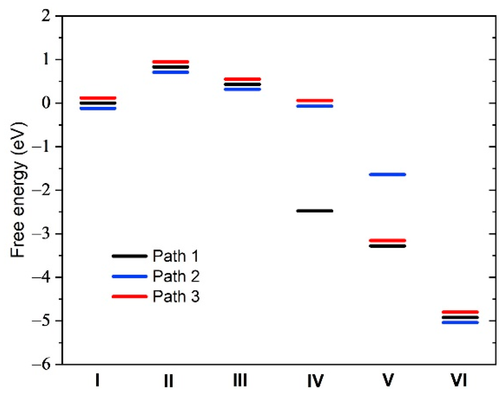
- (1)
- The catalytic activity of the fluorinated Fe/N/C catalyst became similar to that of Fe-free nitrogen-doped carbon catalysts;
- (2)
- The XPS F1s spectra revealed that most Fe sites were associated with a single F atom and fewer were associated with two F atoms;
- (3)
- A total of 70% of the initial activity could be recovered after a heat treatment of the F-poisoned catalyst at 900 °C in Ar.
2. Results
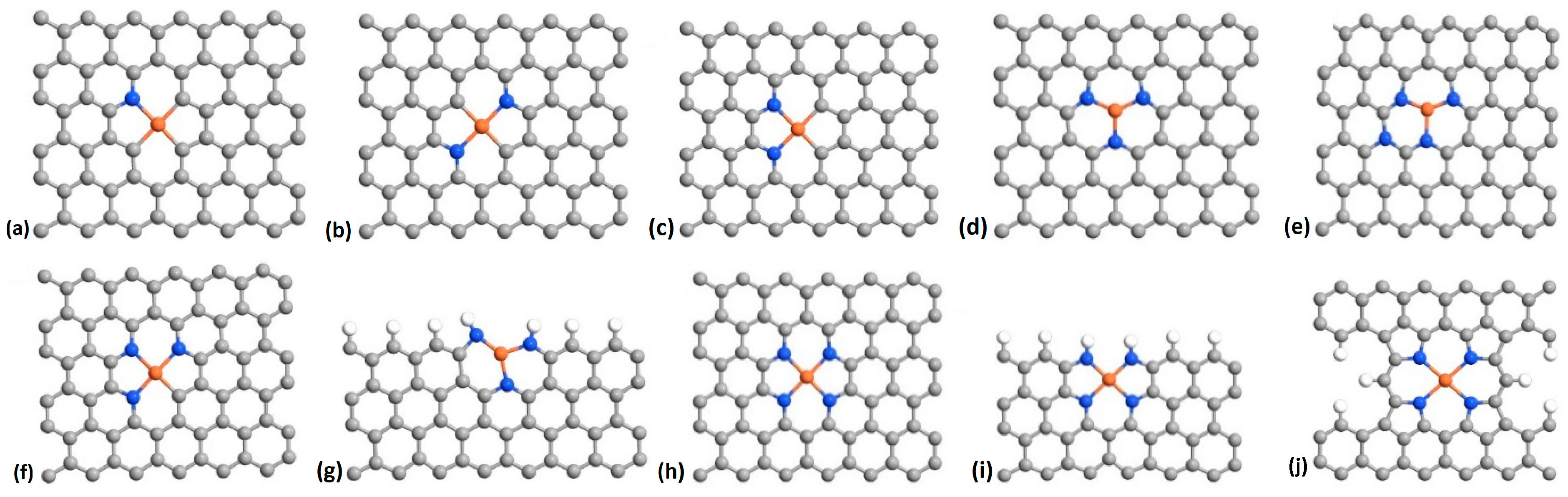
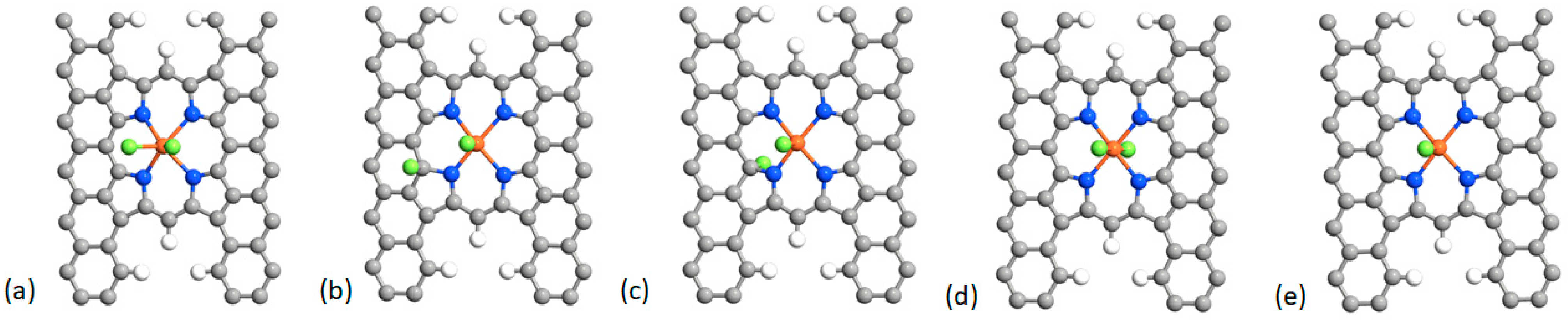
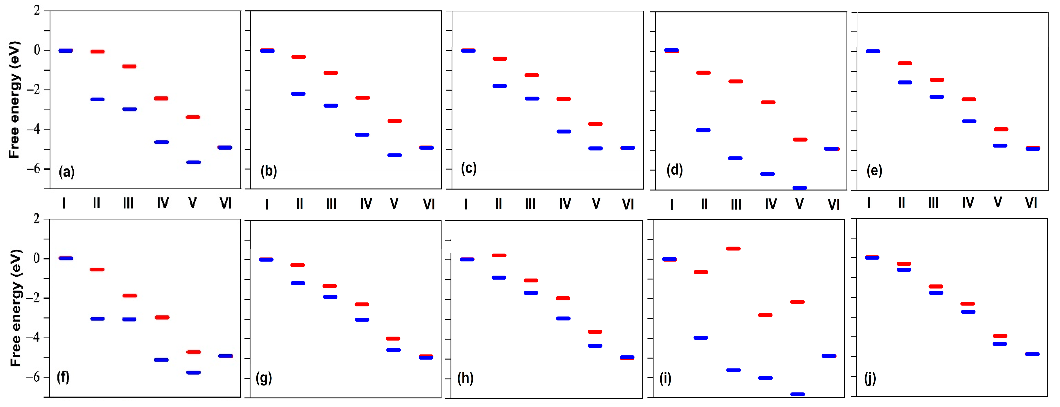
2.1. Fluorination of the FeNx Sites—Single Carbon Layer
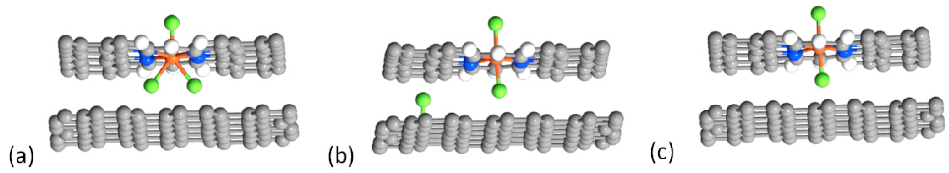
2.2. Fluorination of the FeNx Sites—Double Carbon Layer
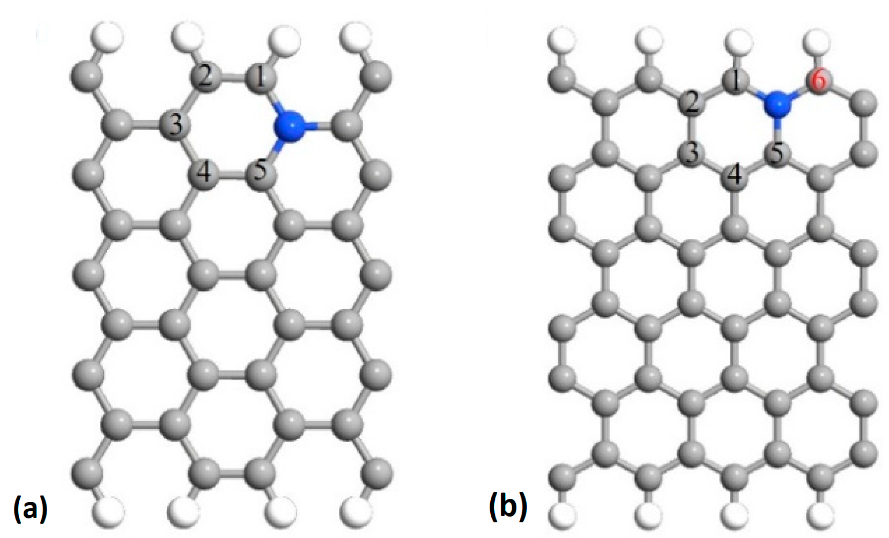
2.3. Fluorination of Metal-Free Sites
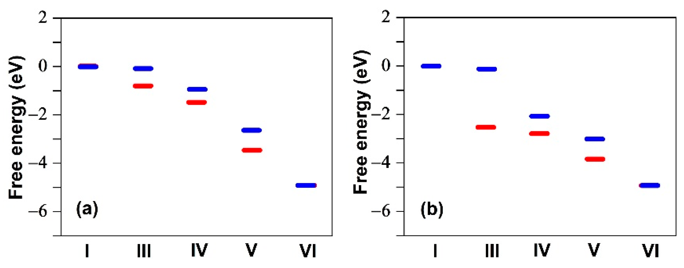
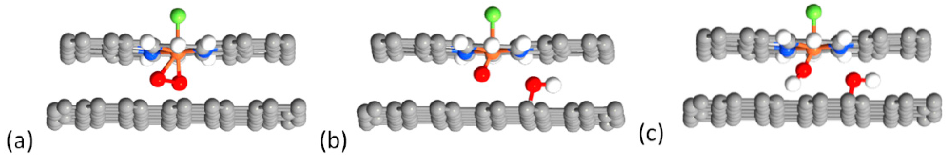
2.4. Defluorination of the FeNx Sites
3. Computational Methods
4. Conclusions
Author Contributions
Funding
Data Availability Statement
Conflicts of Interest
Sample Availability
Appendix A

| Structure/Bond | F–Fe | F–C | F–Fe–F |
|---|---|---|---|
| a | – | – | 1.74, 1.98 |
| b | 1.77 | 1.66 | – |
| c | 1.76 | 1.64 | – |
| d | – | – | 1.78, 2.05 |
| e | 1.79 | – | – |
| Structure/Bond | F–Fe | O–Fe–O | OBO |
|---|---|---|---|
| O2 | – | – | 1.23 |
| Fe–O2 | – | 1.88, 1.88 | 1.35 |
| F–Fe–O2 | 1.80 | 1.92, 1.92 | 1.32 |
| Structure/Position | Site 1 | Site 2 | Site 3 | Site 4 | Site 5 |
|---|---|---|---|---|---|
| Armchair | 1.51 | 1.56 | 1.52 | 1.69 | 1.53 |
| Zigzag | 1.44 | 1.49 | 1.53 | 1.67 | 1.50 |
References
- Debe, M.K. Electrocatalyst approaches and challenges for automotive fuel cells. Nature 2012, 486, 43–51. [Google Scholar] [CrossRef] [PubMed]
- Jaouen, F.; Herranz, J.; Lefèvre, M.; Dodelet, J.P.; Kramm, U.I.; Herrmann, I.; Bogdanoff, P.; Maruyama, J.; Nagaoka, T.; Garsuch, A.; et al. Cross-Laboratory Experimental Study of Non-Noble-Metal Electrocatalysts for the Oxygen Reduction Reaction. ACS Appl. Mater. Interfaces 2009, 1, 1623–1639. [Google Scholar] [CrossRef] [PubMed]
- Jaouen, F.; Proietti, E.; Lefèvre, M.; Chénitz, R.; Dodelet, J.P.; Wu, G.; Chung, H.T.; Johnson, C.M.; Zelenay, P. Recent advances in non-precious metal catalysis for oxygen-reduction reaction in polymer electrolyte fuel cells. Energy Environ. Sci. 2011, 4, 114–130. [Google Scholar] [CrossRef]
- Jaouen, F. Heat-treated transition Metal-Nx-Cy electrocatalysts for the O2 reduction reaction in acid PEM fuel cells. In Non-Noble Metal Fuel Cell Catalysts; Chen, Z., Dodelet, J.P., Zhang, J., Eds.; Wiley-VCH: Weinheim, Germany, 2014; Chapter 2; pp. 29–117. [Google Scholar]
- Shao, M.; Chang, Q.; Dodelet, J.P.; Chenitz, R. Recent Advances in Electrocatalysts for Oxygen Reduction Reaction. Chem. Rev. 2016, 116, 3594–3657. [Google Scholar] [CrossRef] [PubMed] [Green Version]
- Banham, D.; Ye, S.; Pei, K.; Ozaki, J.; Kishimoto, T.; Imashiro, Y. A review of the stability and durability of non-precious metal catalysts for the oxygen reduction reaction in proton exchange membrane fuel cells. J. Power Sources 2015, 285, 334–348. [Google Scholar] [CrossRef]
- Shao, Y.; Dodelet, J.P.; Wu, G.; Zelenay, P. PGM-Free Cathode Catalysts for PEM Fuel Cells: A Mini-Review on Stability Challenges. Adv. Mater. 2019, 31, 1807615. [Google Scholar] [CrossRef]
- Lefèvre, M.; Proietti, E.; Jaouen, F.; Dodelet, J.P. Iron-Based Catalysts with Improved Oxygen Reduction Activity in Polymer Electrolyte Fuel Cells. Science 2009, 324, 71–74. [Google Scholar] [CrossRef] [PubMed]
- Proietti, E.; Jaouen, F.; Lefèvre, M.; Larouche, N.; Tian, J.; Herranz, J.; Dodelet, J.P. Iron-based cathode catalyst with enhanced power density in polymer electrolyte membrane fuel cells. Nat. Commun. 2011, 2, 416. [Google Scholar] [CrossRef] [PubMed]
- Martinez, U.; Babu, S.K.; Holby, E.F.; Chung, H.T.; Yin, X.; Zelenay, P. Progress in the Development of Fe-Based PGM-Free Electrocatalysts for the Oxygen Reduction Reaction. Adv. Mater. 2019, 31, 1806545. [Google Scholar] [CrossRef]
- Asset, T.; Atanassov, P. Iron-Nitrogen-Carbon Catalysts for Proton Exchange Membrane Fuel Cells. Joule 2020, 4, 33–44. [Google Scholar] [CrossRef]
- Dodelet, J.P. The controversial role of the metal in Fe- or Co-based electrocatalysts for the oxygen reduction reaction in acid medium. In Electrocatalysis in Fuel Cells, A Non- and Low- Platinum Approach; Shao, M., Ed.; Springer-Verlag: London, UK, 2013; Chapter 10; pp. 271–338. [Google Scholar]
- Zhang, H.; Ding, S.; Hwang, S.; Zhao, X.; Su, D.; Xu, H.; Yang, H.; Wu, G. Atomically Dispersed Iron Cathode Catalysts Derived from Binary Ligand-Based Zeolitic Imidazolate Frameworks with Enhanced Stability for PEM Fuel Cells. J. Electrochem. Soc. 2019, 166, F3116–F3122. [Google Scholar] [CrossRef]
- Xiao, F.; Xu, G.L.; Sun, C.J.; Xu, M.; Wen, W.; Wang, Q.; Gu, M.; Zhu, S.; Li, Y.; Wei, Z.; et al. Nitrogen-coordinated single iron atom catalysts derived from metal organic frameworks for oxygen reduction reaction. Nano Energy 2019, 61, 60–68. [Google Scholar] [CrossRef]
- Kattel, S.; Wang, G. Reaction Pathway for Oxygen Reduction on FeN4 Embedded Graphene. J. Phys. Chem. Lett. 2014, 5, 452–456. [Google Scholar] [CrossRef]
- Holby, E.F.; Wu, G.; Zelenay, P.; Taylor, C.D. Structure of Fe-Nx-C Defects in Oxygen Reduction Reaction Catalysts from First-Principles Modeling. J. Phys. Chem. C 2014, 118, 14388–14393. [Google Scholar] [CrossRef]
- Holby, E.F.; Zelenay, P. Linking structure to function: The search for active sites in non-platinum group metal oxygen reduction reaction catalysts. Nano Energy 2016, 29, 54–64. [Google Scholar] [CrossRef] [Green Version]
- Matanovic, I.; Artyushkova, K.; Atanassov, P. Understanding PGM-free catalysts by linking density functional theory calculations and structural analysis: Perspectives and challenges. Curr. Opin. Electrochem. 2018, 9, 137–144. [Google Scholar] [CrossRef]
- Ji, Y.; Dong, H.; Liu, C.; Li, Y. The progress of metal-free catalysts for the oxygen reduction reaction based on theoretical simulations. J. Mater. Chem. A 2018, 6, 13489–13508. [Google Scholar] [CrossRef]
- Chenitz, R.; Kramm, U.I.; Lefèvre, M.; Glibin, V.P.; Zhang, G.; Sun, S.; Dodelet, J.P. A specific demetalation of Fe-N4 catalytic sites in the micropores of NC_Ar+NH3 is at the origin of the initial activity loss of the highly active Fe/N/C catalyst used for the reduction of oxygen in PEM fuel cells. Energy Environ. Sci. 2018, 11, 365–382. [Google Scholar] [CrossRef]
- Singh, D.; Tian, J.; Mamtani, K.; King, J.; Miller, J.T.; Ozkan, U.S. A comparison of N-containing carbon nanostructures (CNx) and N-coordinated iron-carbon catalysts (FeNC) for the oxygen reduction reaction in acidic media. J. Catal. 2014, 317, 30–43. [Google Scholar] [CrossRef] [Green Version]
- Mamtani, K.; Ozkan, U.S. Heteroatom-Doped Carbon Nanostructures as Oxygen Reduction Reaction Catalysts in Acidic Media: An Overview. Catal. Lett. 2015, 145, 436–450. [Google Scholar] [CrossRef] [Green Version]
- Mamtani, K.; Singh, D.; Tian, J.; Miller, J.M.; Miller, J.T.; Co, A.C.; Ozkan, U.S. Evolution of N-Coordinated Iron-Carbon (FeNC) Catalysts and Their Oxygen Reduction (ORR) Performance in Acidic Media at Various Stages of Catalyst Synthesis: An Attempt at Benchmarking. Catal. Lett. 2016, 146, 1749–1770. [Google Scholar] [CrossRef]
- Saputro, A.G.; Kasai, H. Density Functional Theory Study on the Interaction of O2 and H2O2 Molecules with the Active Sites of Cobalt-Polypyrrole Catalyst. J. Phys. Soc. Jpn. 2014, 83, 024707. [Google Scholar] [CrossRef]
- Martinez, U.; Babu, S.K.; Holby, E.F.; Zelenay, P. Durability challenges and perspective in the development of PGM-free electrocatalysts for the oxygen reduction reaction. Curr. Opin. Electrochem. 2018, 9, 224–232. [Google Scholar] [CrossRef]
- Yin, X.; Zelenay, P. Kinetic models for the degradation mechanisms of PGM-free ORR catalysts. ECS Trans. 2018, 85, 1239–1250. [Google Scholar] [CrossRef]
- Wang, X.X.; Prabhakaran, V.; He, Y.; Shao, Y.; Wu, G. Iron-Free Cathode Catalysts for Proton-Exchange-Membrane Fuel Cells: Cobalt Catalysts and the Peroxide Mitigation Approach. Adv. Mater. 2019, 31, 1805126. [Google Scholar] [CrossRef]
- Zhang, J.; Zhou, Z.; Wang, F.; Li, Y.; Jing, Y. Two-dimensional metal hexahydroxybenzene frameworks as promising electrocatalysts for an oxygen reduction reaction. ACS Sustain. Chem. Eng. 2020, 8, 7472–7479. [Google Scholar] [CrossRef]
- Li, T.; Li, M.; Zhu, X.; Zhang, J.; Jing, Y. Conductive two-dimensional M3(C6S3O3)2 monolayers as effective electrocatalysts for the oxygen reduction reaction. J. Mater. Chem. A 2021, 9, 24887–24894. [Google Scholar] [CrossRef]
- Berthon-Fabry, S.; Dubau, L.; Ahmad, Y.; Guerin, K.; Chatenet, M. First Insight into Fluorinated Pt/Carbon Aerogels as More Corrosion-Resistant Electrocatalysts for Proton Exchange Membrane Fuel Cell Cathodes. Electrocatalysis 2015, 6, 521–533. [Google Scholar] [CrossRef]
- Asset, T.; Chattot, R.; Maillard, F.; Dubeau, L.; Ahmad, Y.; Batisse, N.; Dubois, M.; Guérin, K.; Labbé, F.; Metkemeijer, R.; et al. Activity and Durability of Platinum-Based Electrocatalysts Supported on Bare or Fluorinated Nanostructured Carbon Substrates. J. Electrochem. Soc. 2018, 165, F3346–F3358. [Google Scholar] [CrossRef]
- Wang, Y.C.; Zhu, P.F.; Yang, H.; Huang, L.; Wu, Q.H.; Rauf, M.; Zhang, J.Y.; Dong, J.; Wang, K.; Zhou, Z.Y.; et al. Surface Fluorination to Boost the Stability of the Fe/N/C Cathode in Proton Exchange Membrane Fuel Cells. ChemElectroChem 2018, 5, 1914–1921. [Google Scholar] [CrossRef]
- Zhang, G.; Yang, X.; Dubois, M.; Herraiz, M.; Chenitz, R.; Lefèvre, M.; Cherif, M.; Vidal, F.; Glibin, V.P.; Sun, S.; et al. Non-PGM electrocatalysts for PEM fuel cells: Effect of fluorination on the activity and stability of a highly active NC_Ar+NH3 catalyst. Energy Environ. Sci. 2019, 12, 3015–3037. [Google Scholar] [CrossRef]
- Li, Y.; Liu, X.; Zheng, L.; Shang, J.; Wan, X.; Hu, R.; Guo, X.; Hong, S.; Shui, J. Preparation of Fe-N-C catalysts with FeNx (x = 1, 3, 4) active sites and comparison of their activities for the oxygen reduction reaction and performances in proton exchange membrane fuel cells. J. Mater. Chem. A 2019, 7, 26147–26153. [Google Scholar] [CrossRef]
- Saputro, G.; Kasai, A.; Asazawa, H.; Kishi, K.; Tanaka, H. Comparative study on the catalytic activity of the TM-N2 active sites (TM = Mn, Fe, Co, Ni) in the oxygen reduction reaction: Density functional theory study. J. Phys. Soc. Jpn. 2013, 82, 114704. [Google Scholar] [CrossRef]
- Xia, D.; Yang, X.; Xie, L.; Wei, Y.; Jiang, W.; Dou, M.; Li, X.; Li, J.; Gan, L.; Kang, F. Direct Growth of Carbon Nanotubes Doped with Single Atomic Fe-N4 Active Sites and Neighboring Graphitic Nitrogen for Efficient and Stable Oxygen Reduction Electrocatalysis. Adv. Funct. Mater. 2019, 29, 1906174. [Google Scholar] [CrossRef]
- Anderson, A.B.; Holby, E.F. Pathways for O2 Electroreduction over Substitutional FeN4, HOFeN4, and OFeN4 in Graphene Bulk Sites: Critical Evaluation of Overpotential Predictions Using LGER and CHE Models. J. Phys. Chem. C 2019, 123, 18398–18409. [Google Scholar] [CrossRef]
- Yan, M.; Dai, Z.; Chen, S.; Dong, L.; Zhang, X.L.; Xu, Y.; Sun, C. Single-Iron Supported on Defective Graphene as Efficient Catalysts for Oxygen Reduction Reaction. J. Phys. Chem. C 2020, 124, 13283–13290. [Google Scholar] [CrossRef]
- Liu, K.; Qiao, Z.; Hwang, S.; Liu, Z.; Zhang, H.; Su, D.; Xu, H.; Wu, G.; Wang, G. Mn- and N-doped carbon as promising catalysts for oxygen reduction reaction: Theoretical prediction and experimental validation. Appl. Catal. B-Environ. 2019, 243, 195–203. [Google Scholar] [CrossRef]
- Li, J.; Chen, M.; Cullen, D.A.; Hwang, S.; Wang, M.; Li, B.; Liu, K.; Karakalos, S.; Lucero, M.; Zhang, H.; et al. Atomically dispersed manganese catalysts for oxygen reduction in proton-exchange membrane fuel cells. Nat. Catal. 2018, 1, 935–945. [Google Scholar] [CrossRef]
- Song, J.; Ren, Y.; Li, J.; Huang, X.; Cheng, F.; Tang, Y.; Wang, H. Core-shell Co/CoNx@C nanoparticles enfolded by Co-N doped carbon nanosheets as a highly efficient electrocatalyst for oxygen reduction reaction. Carbon 2018, 138, 300–308. [Google Scholar] [CrossRef]
- Kattel, S.; Atanassov, P.; Kiefer, B. Catalytic activity of Co-Nx/C electrocatalysts for oxygen reduction reaction: A density functional theory study. Phys. Chem. Chem. Phys. 2013, 15, 148–153. [Google Scholar] [CrossRef] [PubMed]
- Nørskov, J.K.; Rossmeisl, J.; Logadottir, A.; Lindqvist, L.; Kitchin, J.R.; Bligaard, T.; Jonsson, H. Origin of the overpotential for oxygen reduction at a fuel-cell cathode. J. Phys. Chem. B 2004, 108, 17886–17892. [Google Scholar] [CrossRef]
- Zhang, P.; Xiao, B.B.; Hou, X.L.; Zhu, Y.F.; Jiang, Q. Layered SiC Sheets: A Potential Catalyst for Oxygen Reduction Reaction. Sci. Rep. 2015, 4, 3821. [Google Scholar] [CrossRef] [PubMed] [Green Version]
- Li, M.; Zhang, L.; Xu, Q.; Niu, J.; Xia, Z. N-doped graphene as catalysts for oxygen reduction and oxygen evolution reactions: Theoretical considerations. J. Catal. 2014, 314, 66–72. [Google Scholar] [CrossRef]
- Zhang, J.; Wang, Z.; Zhu, Z. A density functional theory study on oxygen reduction reaction on nitrogen-doped graphene. J. Mol. Model. 2013, 19, 5515–5521. [Google Scholar] [CrossRef] [PubMed]
- Ikeda, T.; Hou, Z.; Chai, G.L.; Terakura, K. Possible Oxygen Reduction Reactions for Graphene Edges from First Principle. J. Phys. Chem. C 2014, 118, 17616–17625. [Google Scholar] [CrossRef]
- Zhang, H.; Zhao, J.; Cai, Q. Pyridine derivative/graphene nanoribbon composites as molecularly tunable heterogeneous electrocatalysts for the oxygen reduction reaction. Phys. Chem. Chem. Phys. 2016, 18, 5040–5047. [Google Scholar] [CrossRef]
- Studt, F. The Oxygen Reduction Reaction on Nitrogen-Doped Graphene. Catal. Lett. 2013, 143, 58–60. [Google Scholar] [CrossRef] [Green Version]
- Duan, Z.; Henkelman, G. Identification of Active Sites of Pure and Nitrogen-Doped Carbon Materials for Oxygen Reduction Reaction Using Constant-Potential Calculations. J. Phys Chem. C 2020, 124, 12016–12023. [Google Scholar] [CrossRef]
- Paul, R.; Zhu, L.; Chen, H.; Qu, J.; Dai, L. Recent Advances in Carbon-Based Metal-Free Electrocatalysts. Adv. Mater. 2019, 31, 1806403. [Google Scholar] [CrossRef] [PubMed]
- Glibin, V.P.; Cherif, M.; Vidal, F.; Dodelet, J.P.; Zhang, G.; Sun, S. Non-PGM Electrocatalysts for PEM Fuel Cells: Thermodynamic Stability and DFT Evaluation of Fluorinated FeN4-Based ORR Catalysts. J. Electrochem. Soc. 2019, 166, F3277–F3286. [Google Scholar] [CrossRef]
- Svane, K.L.; Reda, M.; Vegge, T.; Hansen, H.A. Improving the activity of M-N4 catalysts for the oxygen reduction reaction by electrolyte adsorption. ChemSusChem 2019, 12, 5133–5141. [Google Scholar] [CrossRef] [PubMed] [Green Version]
- Rebarchik, M.; Bhandari, S.; Kropp, T.; Mavrikakis, M. How noninnocent spectator species improve the oxygen reduction activity of single-atom catalysts: Microkinetic models from first-principles calculations. ACS Catal. 2020, 10, 9129–9135. [Google Scholar] [CrossRef]
- Yang, Y.; Li, K.; Meng, Y.; Wang, Y.; Wu, Z. A density functional study on the oxygen reduction reaction mechanism on FeN2-doped graphene. New J. Chem. 2018, 42, 6873–6879. [Google Scholar] [CrossRef]
- Szakacs, C.E.; Lefèvre, M.; Kramm, U.I.; Dodelet, J.P.; Vidal, F. A density functional theory study of catalytic sites for oxygen reduction in Fe/N/C catalysts used in H2/O2 fuel cells. Phys. Chem. Chem. Phys. 2014, 16, 13654–13661. [Google Scholar] [CrossRef] [PubMed]
- Hesse, W.M.; Herd, C.R. Microstructure, Morphology and General Physical Properties. In Carbon Black, 2nd ed.; Donnet, J.B., Bansal, R.C., Wang, M.J., Eds.; Marcel Dekker: New York, NY, USA, 1993; Chapter 3; pp. 89–173. [Google Scholar]
- Clementi, E.; Raimondi, D.L.; Reinhardt, W.P. Atomic Screening Constants from SCF Functions. II. Atoms with 37 to 86 Electrons. J. Chem. Phys. 1967, 47, 1300–1307. [Google Scholar] [CrossRef]
- Zhang, G.; Chenitz, G.; Lefèvre, M.; Sun, S.; Dodelet, J.P. Is iron involved in the lack of stability of Fe/N/C electrocatalysts used to reduce oxygen at the cathode of PEM fuel cells? Nano Energy 2016, 29, 111–125. [Google Scholar] [CrossRef]
- Dubois, M.; Guérin, K.; Ahmad, Y.; Batisse, N.; Mar, M.; Frezet, L.; Hourani, W.; Bubendorff, J.L.; Parmentier, J.; Hajar-Garreau, S.; et al. Thermal exfoliation of fluorinated graphite. Carbon 2014, 77, 688–704. [Google Scholar] [CrossRef]
- Kresse, G.; Hafner, J. Ab-initio molecular dynamics for liquid metals. Phys. Rev. B 1993, 47, 558–561. [Google Scholar] [CrossRef] [PubMed]
- Kresse, G.; Hafner, J. Ab-initio molecular dynamics simulation of the liquid metal amorphous semiconductor transition in germanium. Phys. Rev. B 1994, 49, 14251–14269. [Google Scholar] [CrossRef]
- Kresse, G.; Furthmüller, J. Efficiency of ab-initio total energy calculations for metals and semiconductors using a plane-wave basis set. Comput. Mat. Sci. 1996, 6, 15–50. [Google Scholar] [CrossRef]
- Kresse, G.; Furthmüller, J. Efficient iterative schemes for ab initio total-energy calculations using a plane-wave basis set. Phys. Rev. B 1996, 54, 11169–11186. [Google Scholar] [CrossRef] [PubMed]
- Perdew, J.P.; Burke, K.; Ernzerhof, M. Generalized gradient approximation made simple. Phys. Rev. Lett. 1996, 77, 3865–3868. [Google Scholar] [CrossRef] [PubMed] [Green Version]
- Lyalin, A.; Nakayama, A.; Uosaki, K.; Taketsugu, T. Theoretical predictions for hexagonal BN based nanomaterials as electrocatalysts for the oxygen reduction reaction. Phys. Chem. Chem. Phys. 2013, 15, 2809–2820. [Google Scholar] [CrossRef] [PubMed] [Green Version]


| Structure | Binding Energy (eV) |
|---|---|
| a | −1.76 |
| b | −3.12 |
| c | −3.16 |
| d | −7.88 |
| e | −4.56 |
| Structure | Fe–F | F–Fe–F | Fe–O2 |
|---|---|---|---|
| a | −4.27 | −12.10 | −0.84 |
| b | −4.00 | −11.92 | −2.50 |
| c | −3.85 | −11.88 | −2.06 |
| d | −3.94 | −13.04 | −4.60 |
| e | −4.05 | −12.02 | −1.82 |
| f | −4.66 | −12.96 | −3.50 |
| g | −5.89 | −12.94 | −4.55 |
| h | −3.18 | −11.88 | −1.37 |
| i | −2.93 | −10.40 | −1.04 |
| j | −4.56 | −7.88 | −0.71 |
Publisher’s Note: MDPI stays neutral with regard to jurisdictional claims in published maps and institutional affiliations. |
© 2021 by the authors. Licensee MDPI, Basel, Switzerland. This article is an open access article distributed under the terms and conditions of the Creative Commons Attribution (CC BY) license (https://creativecommons.org/licenses/by/4.0/).
Share and Cite
Cherif, M.; Dodelet, J.-P.; Zhang, G.; Glibin, V.P.; Sun, S.; Vidal, F. Non-PGM Electrocatalysts for PEM Fuel Cells: A DFT Study on the Effects of Fluorination of FeNx-Doped and N-Doped Carbon Catalysts. Molecules 2021, 26, 7370. https://doi.org/10.3390/molecules26237370
Cherif M, Dodelet J-P, Zhang G, Glibin VP, Sun S, Vidal F. Non-PGM Electrocatalysts for PEM Fuel Cells: A DFT Study on the Effects of Fluorination of FeNx-Doped and N-Doped Carbon Catalysts. Molecules. 2021; 26(23):7370. https://doi.org/10.3390/molecules26237370
Chicago/Turabian StyleCherif, Mohamed, Jean-Pol Dodelet, Gaixia Zhang, Vassili P. Glibin, Shuhui Sun, and François Vidal. 2021. "Non-PGM Electrocatalysts for PEM Fuel Cells: A DFT Study on the Effects of Fluorination of FeNx-Doped and N-Doped Carbon Catalysts" Molecules 26, no. 23: 7370. https://doi.org/10.3390/molecules26237370
APA StyleCherif, M., Dodelet, J.-P., Zhang, G., Glibin, V. P., Sun, S., & Vidal, F. (2021). Non-PGM Electrocatalysts for PEM Fuel Cells: A DFT Study on the Effects of Fluorination of FeNx-Doped and N-Doped Carbon Catalysts. Molecules, 26(23), 7370. https://doi.org/10.3390/molecules26237370