Abstract
Due to the large application of tapered beams in smart devices, such as scanning tunneling microscopes (STM), nano/micro electromechanical systems (NEMS/MEMS), atomic force microscopes (AFM), as well as in military aircraft applications, this study deals with the vibration behavior of laminated composite non-uniform nanobeams subjected to different boundary conditions. The micro-structural size-dependent free vibration response of composite laminated Euler–Bernoulli beams is here analyzed based on a modified couple stress elasticity, which accounts for the presence of a length scale parameter. The governing equations and boundary conditions of the problem are developed using the Hamilton’s principle, and solved by means of the Rayleigh–Ritz method. The accuracy and stability of the proposed formulation is checked through a convergence and comparative study with respect to the available literature. A large parametric study is conducted to investigate the effect of the length-scale parameter, non-uniformity parameter, size dimension and boundary conditions on the natural frequencies of laminated composite tapered beams, as useful for design and optimization purposes of small-scale devices, due to their structural tailoring capabilities, damage tolerance, and their potential for creating reduction in weight.
1. Introduction
In the last decades, composite structures and materials have received an increased interest in many industries such as the aerospace, automotive, biomedical, architectural, mechanical, and civil sectors [1], due to their high mechanical performances. In particular, micro/nano-scale mechanical structures usually feature a characteristic size of micron or submicron order, e.g., micro/nano-beams, and micro-nano-cylinders, largely used in micro- and nano-electromechanical devices (MEMS and NEMS). Several experimental evidences in literature, have revealed that the behavior of micro-structures is size-dependent [2,3,4,5]. Thus, a large number of works has been recently published to conceive novel structural solutions, systems, and devices, while adopting different types of reinforcement phase, such as graphene nanoplatelets [6,7,8,9,10,11,12,13,14], or carbon nanotubes [15,16,17,18,19]. Among a large variety of numerical strategies, higher order theories represent the most useful tool for the investigation of the static and dynamic response of materials at different scales [20,21,22,23,24]. Classical theories, indeed, have largely revealed to be inaccurate for the study of nano- or micro-structures. This has increased the adoption of higher-order continuum theories that include the size dependence of materials, e.g., the coupled stress theory (CST), the modified couple stress theory (MCST), the novel modified couple stress theory (NMCST), the strain gradient theory, the modified strain gradient theory, the Eringen’s nonlocal theory, among others. For nano- or micro-sized beam applications, a Timoshenko beam model was developed by Ma et al. [25] based on a MCST for a microstructure-dependent analysis of the static bending and free vibration response of the structure. The small-scale static, buckling, and/or postbuckling behavior of functionally graded (FG) micro- or nano-beams was successfully investigated in References [26,27,28] using different beam theories with the MCST, while focusing on the sensitivity of the response to size-dependent scale parameters.
In the further works [29,30,31,32,33,34], the nonlocal MCST was combined to the Euler–Bernoulli or Timoshenko nanocomposite FG beams subjected to a moving load, also in coupled-loading conditions. Some novel coupled-stress based models have been recently employed to study the microstructure-dependent structural behavior of laminated systems, and to predict possible-size effects from subscales (e.g., the interaction among fibers or voids within laminae) to upper scales by considering the gradients of displacement as micro-rotations [35,36,37,38,39,40]. Moreover, in References [41,42], the authors investigated the vibration behavior of doubly-curved shells in a general orthogonal curvilinear coordinate systems. In line with the previous works, Kim et al. [43] studied the bending, buckling and vibration behavior of microplates made of FG porous material, whereas Mahmoudpour et al. [40] investigated the nonlinear forced vibration behavior of embedded FG double layered nanoplates. For further interesting studies based on the application of higher order theories, the reader is referred to References [44,45,46,47,48]. For similar problems, it is worth noticing that the governing equations of such systems are essentially non-linear, such that a closed-from solution is usually difficult to be found, unless some appropriate simplifications are considered. In many cases, however, the application of different numerical methods is unavoidable [49,50].
Due to the optimization requirements in the engineering structural design, the non-uniform materials and tapered geometries with a progressive variation in thickness and/or width, are increasingly adopted in a wide range of applications at different scales, such as in tennis rackets, aerospace, mechanical engineering structures (micro-pumps, accelerometers etc.), military aircraft (composite aircraft-wing skins, helicopter flexbeams, fly-wheels), devices (NEMS/MEMS), and civil engineering structures, due to their tailoring elastic properties, along with a high stiffness-to-weight and strength-to-weight ratios. In this context, Lal and Dangi [51] studied the vibration behavior of bi-directional FG non-uniform Timoshenko nanobeams. Rajasekaran and Khaniki [52] investigated the bending, buckling and vibration of tapered beams at a nanoscale. Akgoz and Civalek [53] investigated the buckling behavior of tapered microbeams by means of strain gradient theories, and applied the Rayleigh–Ritz method to solve the problem in terms of buckling load for different non-uniformity ratios. Other applications of the strain gradient theory for the vibration and/or buckling analysis of small-scale beams with a non-uniform geometry and material, can be found in References [54,55,56,57,58,59], where, in most cases, the differential quadrature method has been applied to solve the governing equations of the problem. In the further work by Aranda-Ruiz et al. [60], the authors analyzed the flapwise bending vibration response of a tapered rotating nanocantilever beam through the Eringen’s nonlocal elastic theory, while using the pseudospectral collocation method based on Chebyshev polynomials to solve the problem. Based on a large parametric investigation, a pronounced sensitivity of the dynamic response was found to the nonlocal small scale, angular speed and non-uniform section of the nanocantilever.
Despite the large application of nonlocal elastic theories, few works in the literature have applied the coupled stress theories (CSTs) to describe the mechanical behavior of non-uniform small scale beams [61,62,63,64], and found some closed form solutions for some particular loading and boundary conditions. This represents the main concern of the present investigation, where we propose a NMCST as higher-order continuum-based theory for the vibration size-dependent analysis of tapered composite beams with arbitrary lay-ups. The formulation proposed in this work starts considering similar CST-based assumptions as in Ref. [35], which are here generalized to handle composite laminated Euler–Bernoulli beams with a more complicated tapered geometry and different boundary conditions. Among different numerical approaches, in the present work we apply a Ritz-type solution with harmonic trial functions to solve the problem, whose stability and accuracy is verified through a systematic investigation. In line with predictions from the literature [65,66,67,68,69,70,71,72,73], the Rayleigh–Ritz method, represents an efficient tool for the analysis of the structural behavior of beams, whose accuracy and stability are well known to be related to the selected trial functions. The trial functions must satisfy the enforced boundary conditions. When this condition is not fulfilled, the Lagrangian multipliers and penalty method could be adopted to handle arbitrary boundary conditions. This approach, however, can cause an overall increase in dimension for both the stiffness and mass matrices, with a consecutive increase in the computational cost. Therefore, in the present work we first check for the stability of the numerical solution for the selected harmonic trial functions, by means of a systematic investigation. The numerical study also aims at evaluating the sensitivity of the response to different geometrical and/or mechanical parameters, which could be of great interest for design purposes in practical engineering application, and could serve for future studies on non-uniform beams and devices.
The outline of the paper is as follows: in Section 2 we introduce the mathematical problem for tapered nanobeams, which is solved numerically by means of the Ritz method in Section 3. The numerical examples and applications are discussed comparatively in Section 4 for different mechanical and geometrical parameters. Finally, in Section 5, we draw the main conclusions of our work.
2. Theory and Mathematical Problem
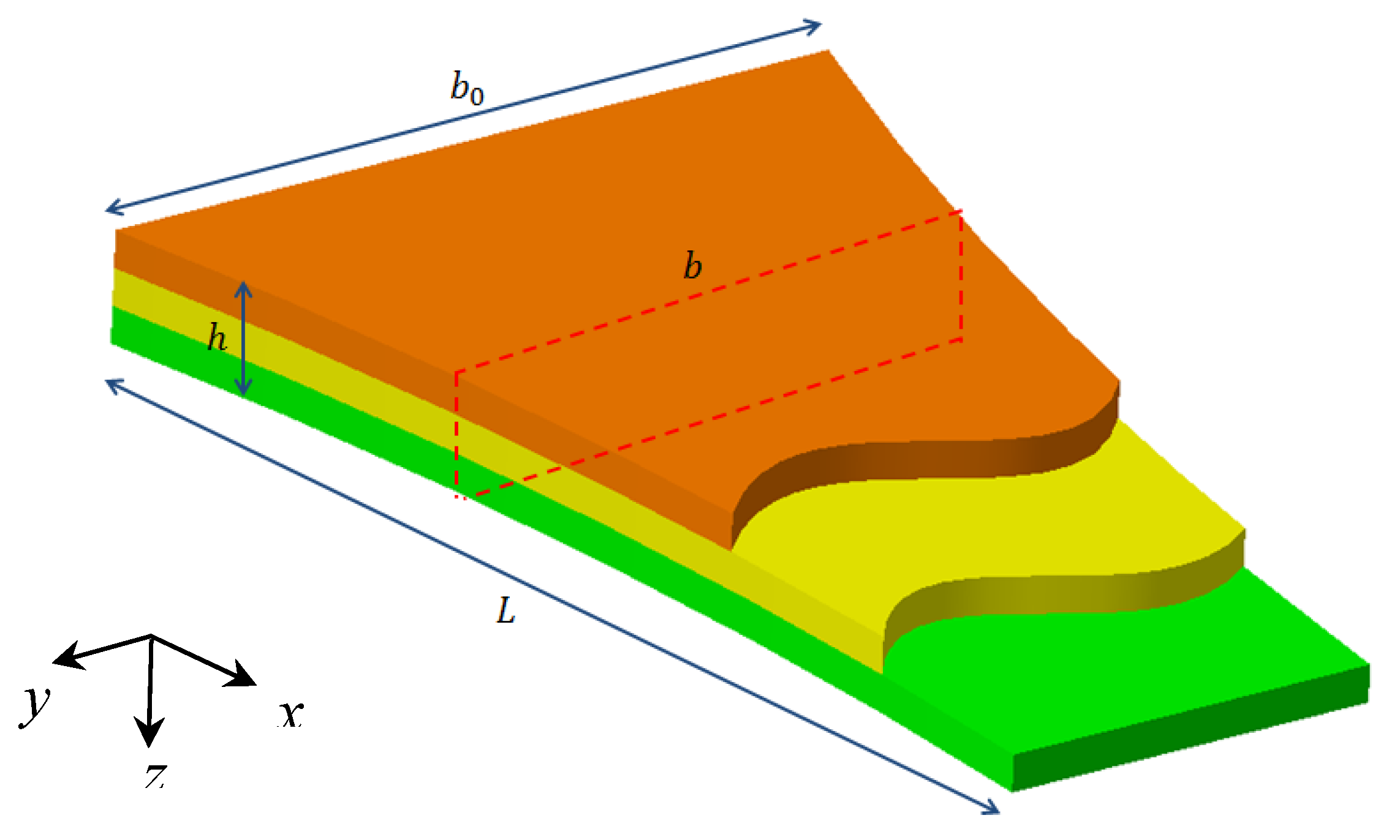
Let us consider the orthotropic non-uniform nanobeam in Figure 1, with length , constant thickness , variable width , in a Cartesian coordinate system (x,y,z).
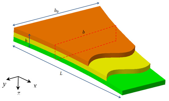
Figure 1.
Geometry of the laminated composite nanobeam.
Based on the Timoshenko beam theory, the displacement field , is defined by its components, as follows [35,61]:
where and are the axial and transverse displacements of an arbitrary point of the mid-plane along the x- and z-directions, respectively, whereas is the angle of rotation around the y-axis of the cross section, that will be defined as for an Euler–Bernoulli formulation.
Based on the NMCST, the rotational field is defined by the following components:
The non-null components of the strain tensor for the ply of a laminated beam, are governed by the following kinematic relations:
where becomes equal to zero according to Euler–Bernoulli theory.
In line with the NMCST proposed in [35], we introduce the constitutive relations for the ply of a laminated micro-composite beam, in the global system of coordinates, where two length scale parameters are introduced, and for fibers and matrix in the lamina, respectively. More specifically, refers to the micro-scale material constant of an arbitrary fiber rotating in the plane, where the fiber is considered as the impurity affecting the rotational equilibrium; stands for the micro-scale material constant within the matrix rotating about the impurity in the plane.
Thus, the stress-strain relations in the global coordinate system, are expressed in compact form as:
where , , stand for the modified couple stresses, and depends on the coordinate transformation matrix and on the elastic properties matrix , defined as follows:
In the matrix (5), is the fiber angle of a layer with respect to the -axis, while the elastic stiffness components in matrix (6) are defined as in Reference [35]:
with and the shear and normal elastic modulus, respectively, and the Poisson ratios.
Once the coordinate transformation from a local to the global system is performed, the constitutive relations take the following form:
where the elastic coefficients are defined as [35]:
Starting with the above-mentioned constitutive relations for composite laminated beams based on the NMCST, we determine the governing equations of motion by means of the Hamilton’s principle. In absence of external forces acting on the structure, the total potential energy takes the following form:
and being the strain energy and the kinetic energy, respectively. More specifically, the strain energy of the beam is defined, in the domain , as follows:
which is combined to Equations (3) and (4) to yield the following expression:
Under the Euler–Bernoulli assumption of the type , Equation (12) becomes:
where
and refers to the non-uniform width, whose variation is defined as:
where is the width of the tapered beam, at and is the exponential non-uniform parameter.
The kinetic energy in Equation (10) is expressed as follows:
For a Euler–Bernoulli beam formulation, Equation (16) becomes as follows:
with
By a combination of Equations (10), (13), (17) we get the following expression for the total energy for the Euler–Bernoulli beam:
3. The Rayleigh–Ritz Procedure
The Rayleigh–Ritz method, with two different exponential trial functions, is here applied to approximate the displacement field as proposed by Nguyen et al. [72], and determine the solution of the problem. Thus, the kinematic quantities are approximated as follows:
where is the natural frequency, refers to the imaginary unit, are the unknowns of the problem, and are the trial functions which depend on the selected boundary conditions. In the present study we consider two different types of boundary conditions, namely simply supports (S-S) and clamped-free (C-F) supports, such that the following trial functions are assumed [71]:
Upon substitution of Equations (20), (21) into Equation (19), and by using the Lagrange’s equations, we get the following relation:
being the values of , that describe the vibration response of the tapered beam structure. After some mathematical manipulation, the generalized eigenvalue problem gets the following form
where and stand for the stiffness and mass matrix, respectively, whose components are defined as follows:
The natural frequencies of the orthotropic nanostructure are, finally, determined through the enforcement of the following condition:
4. Numerical Results and Discussion
In this section, we present the results of different numerical examples, selected to test the accuracy of the formulation with respect to the available literature, and the sensitivity of the free vibration response to the boundary conditions, length-scale parameter, non-uniformity parameter, or size dimension.
For validation purposes, we compute the first five natural frequencies for a S-S three-layer [90°,0°,90°] microbeam, with the following geometrical properties: b = h = 25 × 10−6 m, L = 200 × 10−6 m. The mechanical properties of the material are assumed as in Reference [35], i.e., E2 = 6.9 × 10⁹ Pa, E1 = 25E2, G12 = G13 = 0.5E2, G23 = 0.2E2, ν12 = ν13 = ν23 = 0.25, ρ = 1.578 kg/m3. Table 1 summarizes the results for the first five frequency parameters, and different values of . As clearly visible in Table 1, represents a convergence point for the numerical computation of the natural frequencies. This value of is assumed hereafter for the parametric study.

Table 1.
Convergence study for first five natural frequency of the S-S three-layer [90°,0°,90°] Euler–Bernoulli beam.
A further comparative example is chosen to assess the capabilities of the present formulation, namely, an isotropic S-S uniform nanobeam, as proposed originally by Chen and Li [35]. The first five natural frequencies computed with our formulation are compared to predictions by Chen and Li [35], as summarized in Table 2, for a different length-scale parameter. A good agreement with the available literature is observed, which confirms the accuracy of the proposed formulation, along with a general increase of each natural frequency for an increased length-scale parameter. Small differences between our predictions and the ones in Reference [35] are noticed for an increased length scale parameter. This is mainly related to the different basic assumptions considered in the two works, namely a Euler–Bernoulli beam model instead of a Timoshenko-based formulation. In agreement with findings by Reference [35], it seems that an Euler–Bernoulli-based formulation gets higher natural frequencies than a Timoshenko-based theory.

Table 2.
Comparative study for the first five natural frequency of the S-S three-layer [90°,0°,90°] Euler–Bernoulli beam.
After the preliminary validation, we perform a parametric analysis of the vibration response for an orthotropic non-uniform nanobeam under two different sets of boundary condition, while including the effects of size, length-scale and non-uniformity. A three layer [90°,0°,90°] non-uniform nanobeam is considered, with h = 10 nm, b0 = 2 h, different values of L, and material properties stemming from Reference [23], i.e., E2 = 13.67 GPa, E1 = 37.41 GPa, G12 = 6.03 GPa, G13 = 6.03 GPa, G23 = 6.67 GPa, ν12 = ν13 = ν23 = 0.3, ρ = 1938.9 kg/m3.
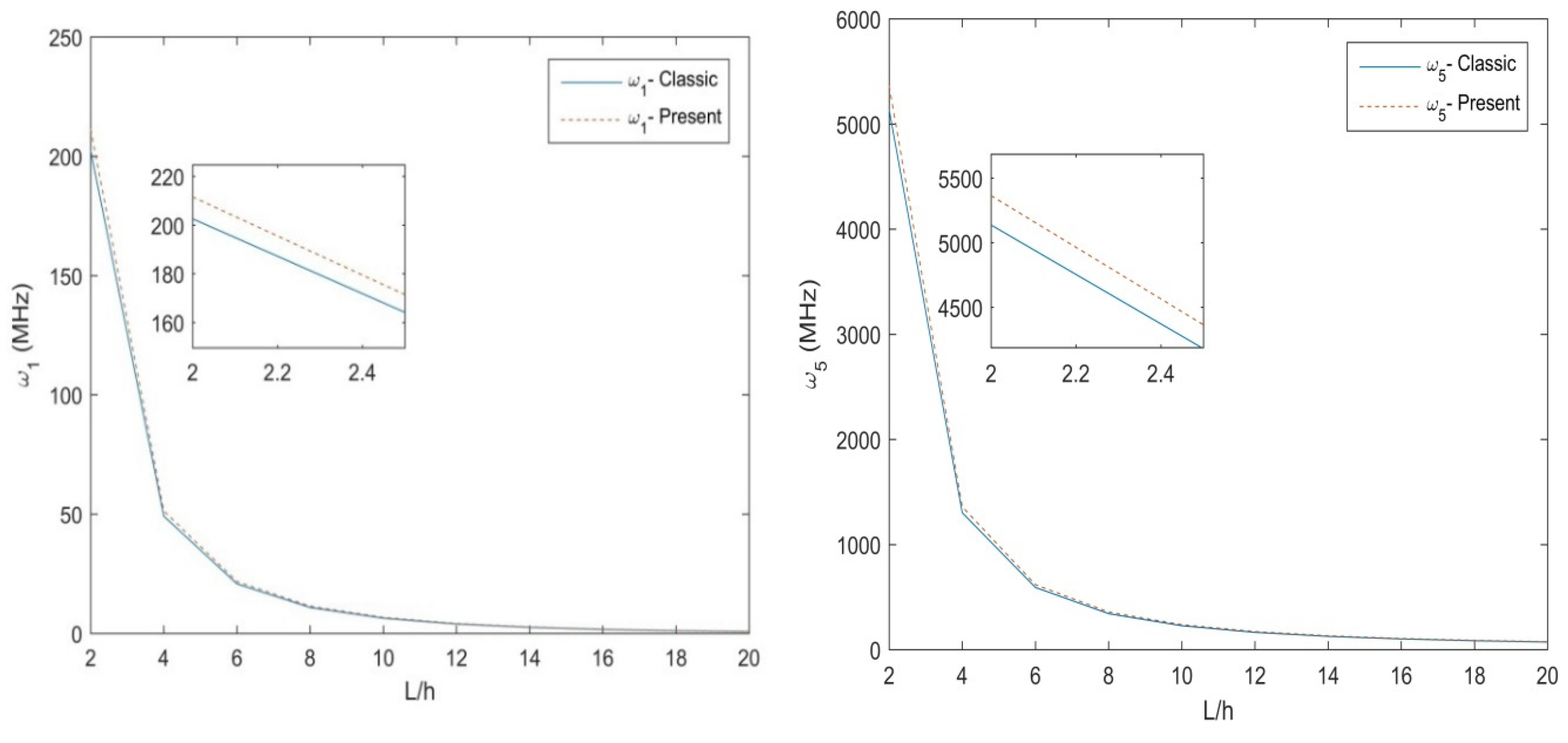
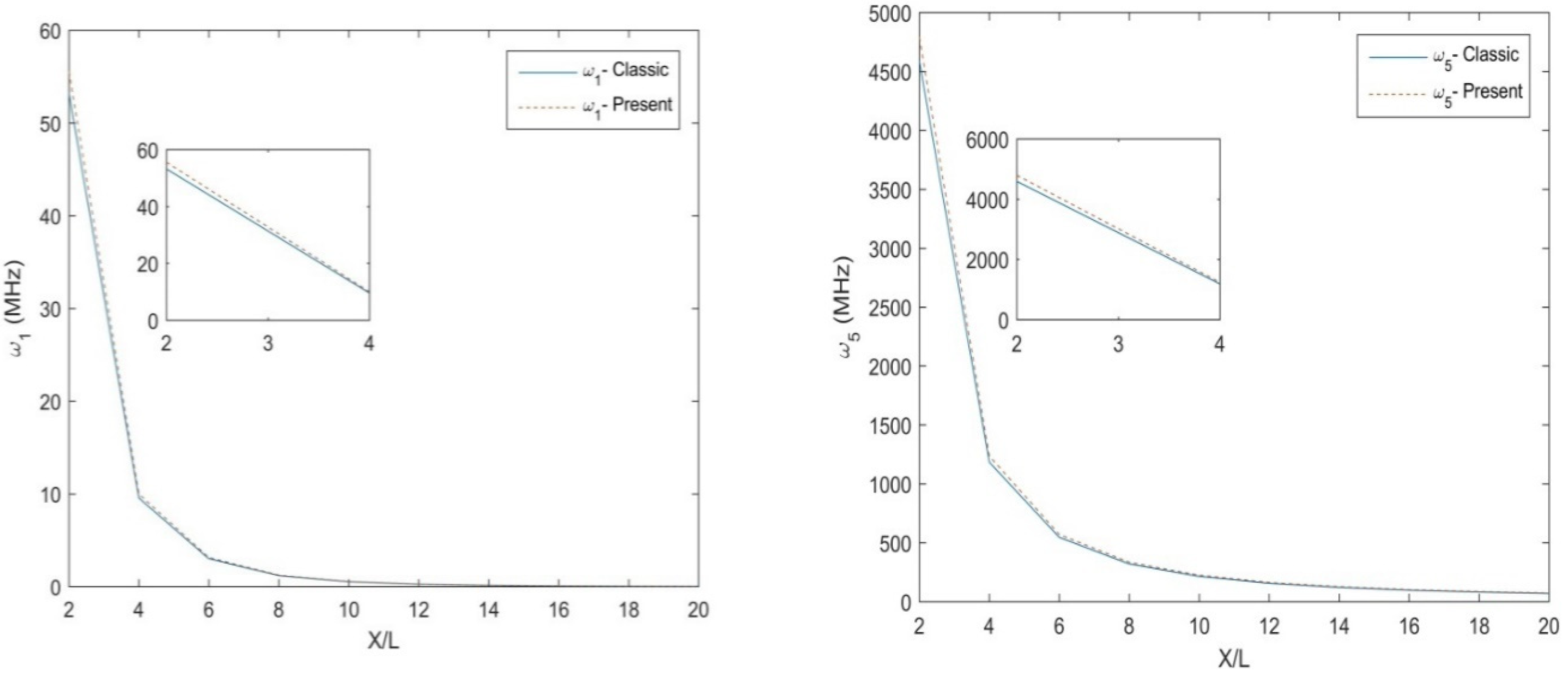
Table 3 and Table 4 illustrate the main results in terms of natural frequency for different size ratios, , non-uniformity parameter, , length scale, l, for a S-S and C-F non-uniform nanobeam, respectively. Based on these tables, an increased length scale and a decreased size ratio leads to an overall increase of the natural frequencies. A non-monotonic behavior, instead, is exhibited by the natural frequencies for an increasing non-uniformity , while keeping fixed the other parameters. In Figure 2, we plot the variation of the first and the fifth natural frequencies for a three-layer [90°,0°,90°] Euler-Bernoulli S-S non-uniform beam with size ratio , and fixed values of h = 10 nm, b0 = 2 h, Nh = 0.5. The NMCST under the assumption of l = 1 nm is here compared to the classical approach (i.e., for l = 0 nm). As clearly shown in Figure 2, the classical theory predicts lower values of natural frequencies with respect to the NMCST here proposed, whereby, both natural frequencies () decrease for increased geometrical lengths of nanobeams. The parametric study is thus repeated for a C-F nanobeam, whose results are plotted in Figure 3 in terms of the natural frequencies , while assuming the same geometrical and mechanical parameters as in the previous investigation. Additionally, in this case, the NMCST yields higher values of natural frequencies compared to a classical approach. The main difference between the two approaches, in this case, is less pronounced because of the lower deformability of the C-F nanobeam compared to a S-S boundary condition.

Table 3.
Natural frequency of the S-S three-layer [90°,0°,90°] Euler–Bernoulli beams.

Table 4.
Natural frequency of the C-F three-layer [90°,0°,90°] Euler–Bernoulli beams.
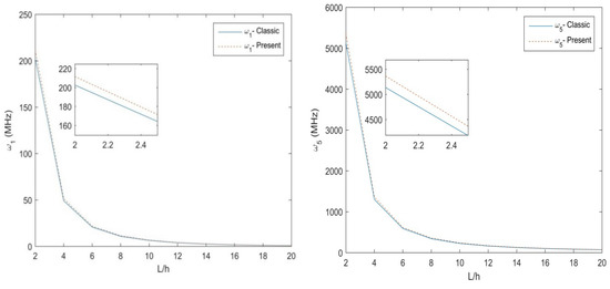
Figure 2.
The 1st and 5th natural frequency for the S-S three-layer [90°,0°,90°] Euler–Bernoulli non-uniform beam.
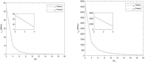
Figure 3.
The 1st and 5th natural frequency of the C-F three-layer [90°,0°,90°] Euler–Bernoulli non-uniform beams.
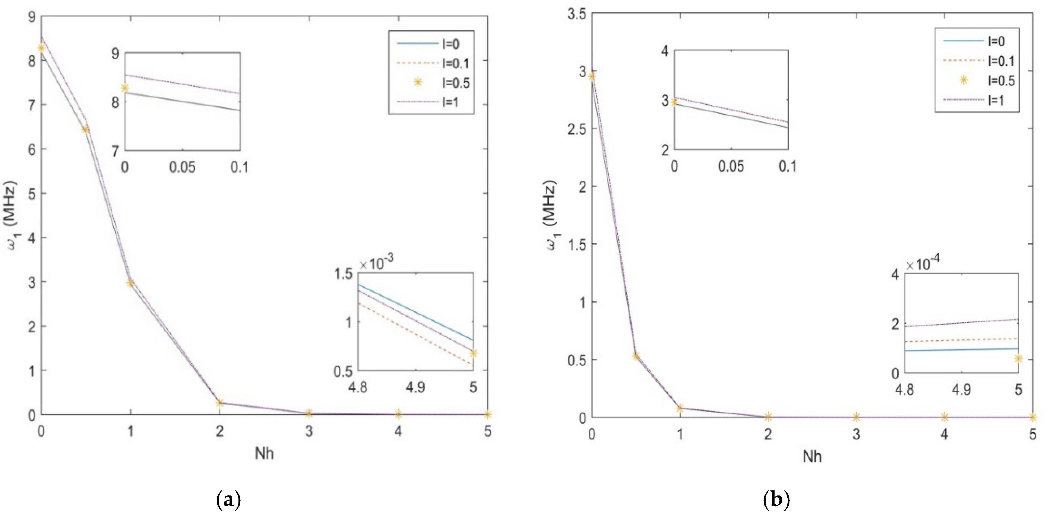
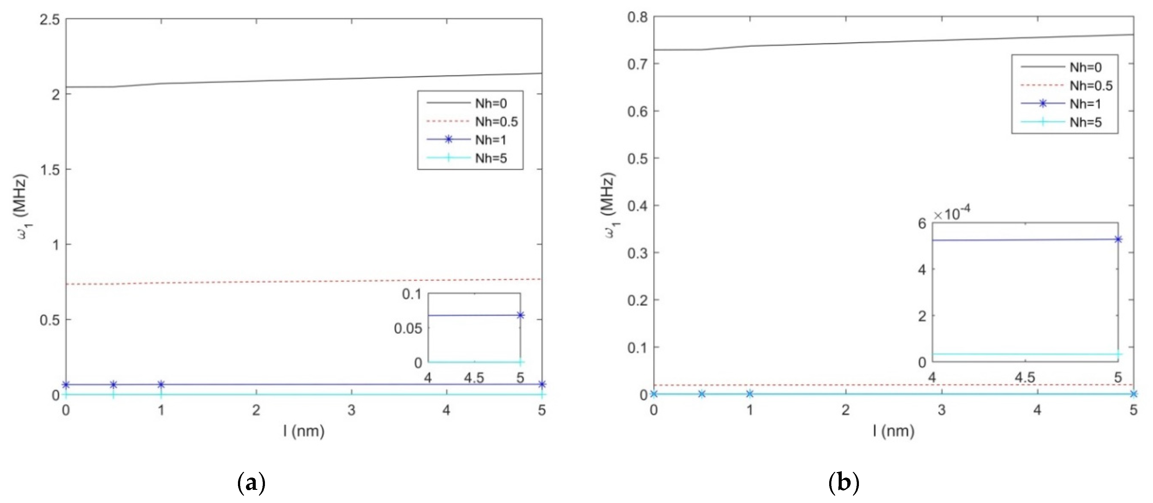
In Figure 4a,b, we plot the first natural frequency vs. the non-uniformity parameter , for the S-S and C-F non-uniform nanobeam, along with different length scale parameters, namely, l = 0; 0.1; 0.5; 1, and a fixed geometry h = 10 nm, b0 = 2h, L/h = 10. As shown in Figure 4, for both sets of boundary conditions, the natural frequency decreases with an increased non-uniformity parameter (see the zoom-ups of Figure 4). Moreover, the natural frequency decreases monotonically between Nh = 0 and Nh = 3 or 2, depending on the selected boundary condition, with a drastic reduction up to a null asymptotic value. A monotone increase of the natural frequency is also observed for an increasing length scale parameter l, at least for lower values of , whose variation is finally visualized in Figure 5a,b, for a S-S- and C-F nanostructure, respectively. Based on the last results, it seems that uniform beams are more sensitive to the length parameter, compared to tapered geometries, which could be accounted for design purposes of nanodevises.
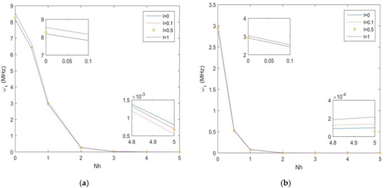
Figure 4.
The 1st natural frequency for a S-S (a) and C-F (b) beam vs. non-uniformity parameter for different length-scales.
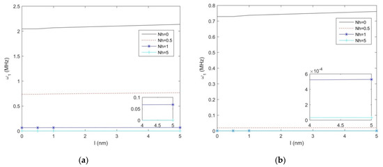
Figure 5.
The 1st natural frequency variation for a S-S (a) and C-F (b) beam vs. length scale parameter for different non-uniformity parameters.
5. Conclusions
In this work, we employ a novel modified couple stress theory for studying the vibration response of laminated composite non-uniform beams under two different boundary conditions. The problem is tackled with the Rayleigh–Ritz formulation, here proposed as promising numerical approach to predict the size-dependent responses of micro composite beams. This is verified through a comparative study with the available literature, at least for uniform geometries. A parametric investigation is, thus, repeated systematically to check for the sensitivity of the vibration behavior for non-uniform nanobeams with different geometrical shape, non-uniformity parameter, length scale parameter, and boundary condition. The numerical outcomes show that the length-to-thickness ratio, non-uniformity, and boundary condition, play a key role in the vibration response of the nanostructure, compared to the length-scale sensitivity. More specifically, an increased length scale and a decreased size ratio yields an overall increase in the natural frequencies, along with an increased stiffness. As expected, a classical theory predicts lower values of natural frequencies with respect to the NMCST here proposed, whereby, an increased geometrical length of the nanobeams yields an overall decrease in the natural frequencies and structural stiffness. In addition, an increased non-uniformity in the beam gets lower natural frequencies. This means that the non-uniformity parameter of a tapered beam could enable a tailorable stiffness and vibration response, depending on the design requirements. These conclusions could be of interest for the nanotechnology community, as well as for design purposes and optimization processes of many engineering nanodevices, nanoelectronics, or nanosensors. The basic notions of the formulation here proposed, could be also used to treat other mechanical aspects, such as buckling problems or fracture mechanics problems of tapered beams.
Author Contributions
Conceptualization, F.Z.J., H.B., R.D. and F.T.; Formal analysis, F.Z.J., H.B., R.D. and F.T.; Investigation, F.Z.J., H.B. and F.T.; Validation, F.Z.J., R.D. and F.T.; Writing—Original Draft, F.Z.J., H.B., R.D. and F.T.; Writing—Review & Editing, R.D. and F.T. All authors have read and agreed to the published version of the manuscript.
Funding
This research received no external funding.
Conflicts of Interest
The authors declare no conflict of interest.
References
- Stürzenbecher, R.; Hofstetter, K. Bending of cross-ply laminated composites: An accurate and efficient plate theory based upon models of Lekhnitskii and Ren. Compos. Struct. 2011, 93, 1078–1088. [Google Scholar] [CrossRef]
- Fleck, N.A.; Muller, G.M.; Ashby, M.F.; Hutchinson, J.W. Strain gradient plasticity: Theory and experiment. Acta Metall. Mater. 1994, 42, 475–487. [Google Scholar] [CrossRef]
- Stolken, J.S.; Evans, A.G. A microbend test method for measuring the plasticity length scale. Acta Mater. 1998, 46, 5109–5115. [Google Scholar] [CrossRef]
- Lam, D.C.C.; Yang, F.; Chong, A.C.M.; Wang, J.; Tong, P. Experiments and theory in strain gradient elasticity. J. Mech. Phys. Solids 2003, 51, 1477–1508. [Google Scholar] [CrossRef]
- McFarland, A.W.; Colton, J.S. Role of material microstructure in plate stiffness with relevance to microcantilever sensors. J. Micromech. Microeng. 2005, 15, 1060–1067. [Google Scholar] [CrossRef]
- Chen, D.; Yang, J.; Kitipornchai, S. Nonlinear vibration and postbuckling of functionally graded graphene reinforced porous nanocomposite beams. Compos. Sci. Technol. 2017, 142, 235–245. [Google Scholar] [CrossRef]
- Feng, C.; Kitipornchai, S.; Yang, J. Nonlinear bending of polymer nanocomposite beams reinforced with non-uniformly distributed graphene platelets (GPLs). Compos. Part B Eng. 2017, 110, 132–140. [Google Scholar] [CrossRef]
- Feng, C.; Kitipornchai, S.; Yang, J. Nonlinear free vibration of functionally graded polymer composite beams reinforced with graphene nanoplatelets (GPLs). Eng. Struct. 2017, 140, 110–119. [Google Scholar] [CrossRef]
- Kitipornchai, S.; Chen, D.; Yang, J. Free vibration and elastic buckling of functionally graded porous beams reinforced by graphene platelets. Mater. Des. 2017, 116, 656–665. [Google Scholar] [CrossRef]
- Sahmani, S.; Aghdam, M.M. Nonlocal strain gradient beam model for nonlinear vibration of prebuckled and postbuckled multilayer functionally graded GPLRC nanobeams. Compos. Struct. 2017, 179, 77–88. [Google Scholar] [CrossRef]
- Wang, Y.; Feng, C.; Zhao, Z.; Yang, J. Buckling of Graphene Platelet Reinforced Composite Cylindrical Shell with Cutout. Int. J. Struct. Stab. Dyn. 2018, 18, 1850040. [Google Scholar] [CrossRef]
- Arefi, M.; Bidgoli, E.M.R.; Dimitri, R.; Tornabene, F.; Reddy, J.N. Size-Dependent Free Vibrations of FG Polymer Composite Curved Nanobeams Reinforced with Graphene Nanoplatelets Resting on Pasternak Foundations. Appl. Sci. 2019, 9, 1580. [Google Scholar] [CrossRef]
- Arefi, M.; Bidgoli, E.M.R.; Dimitri, R.; Bacciocchi, M.; Tornabene, F. Nonlocal bending analysis of curved nanobeams reinforced by graphene nanoplatelets. Compos. Part B Eng. 2019, 166, 1–12. [Google Scholar] [CrossRef]
- Jalaei, M.H.; Dimitri, R.; Tornabene, F. Dynamic stability of temperature-dependent graphene sheet embedded in an elastomeric medium. Appl. Sci. 2019, 9, 887. [Google Scholar] [CrossRef]
- Arefi, M.; Mohammadi, M.; Tabatabaeian, A.; Dimitri, R.; Tornabene, F. Two-dimensional thermo-elastic analysis of FG-CNTRC cylindrical pressure vessels. Steel Compos. Struct. 2018, 27, 525–536. [Google Scholar]
- Kiani, Y.; Dimitri, R.; Tornabene, F. Free vibration of FG-CNT reinforced composite skew cylindrical shells using the Chebyshev-Ritz formulation. Compos. Part B Eng. 2018, 147, 169–177. [Google Scholar] [CrossRef]
- Kiani, Y.; Dimitri, R.; Tornabene, F. Free vibration study of composite conical panels reinforced with FG-CNTs. Eng. Struct. 2018, 172, 472–482. [Google Scholar] [CrossRef]
- Ghasemi, A.R.; Mohandes, M.; Dimitri, R.; Tornabene, F. Agglomeration effects on the vibrations of CNTs/fiber/polymer/metal hybrid laminates cylindrical shell. Compos. Part B Eng. 2019, 167, 700–716. [Google Scholar] [CrossRef]
- Mohammadi, M.; Arefi, M.; Dimitri, R.; Tornabene, F. Higher-order thermo-elastic analysis of FG-CNTRC cylindrical vessels surrounded by a pasternak foundation. Nanomaterials 2019, 9, 79. [Google Scholar] [CrossRef]
- Tornabene, F.; Fantuzzi, N.; Bacciocchi, M.; Viola, E. Mechanical behavior of damaged laminated composites plates and shells: Higher-order shear deformation theories. Compos. Struct. 2018, 189, 304–329. [Google Scholar] [CrossRef]
- Asadi, A.; Sheikh, A.H.; Thomsen, O.T. Buckling behaviour of thin-walled laminated composite beams having open and closed sections subjected to axial and end moment loading. Thin Walled Struct. 2019, 141, 85–96. [Google Scholar] [CrossRef]
- Karamanli, A.; Aydogdu, M. Buckling of laminated composite and sandwich beams due to axially varying in-plane loads. Compos. Struct. 2019, 210, 391–408. [Google Scholar] [CrossRef]
- Kim, K.; Choe, K.; Kim, S.; Wang, Q. A modeling method for vibration analysis of cracked laminated composite beam of uniform rectangular cross-section with arbitrary boundary condition. Compos. Struct. 2019, 208, 127–140. [Google Scholar] [CrossRef]
- Tornabene, F.; Fantuzzi, N.; Bacciocchi, M. Refined shear deformation theories for laminated composite arches and beams with variable thickness: Natural frequency analysis. Eng. Anal. Bound. Elem. 2019, 100, 24–47. [Google Scholar] [CrossRef]
- Ma, H.M.; Gao, X.-L.; Reddy, J.N. A microstructure-dependent Timoshenko beam model based on a modified couple stress theory. J. Mech. Phys. Sol. 2008, 56, 3379–3391. [Google Scholar] [CrossRef]
- Mohammadimehr, M.; Mahmudian-Najafabadi, M. Bending and Free Vibration Analysis of Nonlocal Functionally Graded Nanocomposite Timoshenko Beam Model Rreinforced by SWBNNT Based on Modified Coupled Stress Theory. J. Nanostruct. 2013, 3, 483–492. [Google Scholar]
- Akbarzadeh Khorshidi, M.; Shariati, M.; Emam, S.A. Postbuckling of functionally graded nanobeams based on modified couple stress under general beam theory. Int. J. Mech. Sci. 2016, 110, 160–169. [Google Scholar] [CrossRef]
- Ilkhani, M.R.; Hosseini-Hashemi, S.H. Size dependent vibro-buckling of rotating beam based on modified couple stress theory. Compos. Struct. 2016, 143, 75–83. [Google Scholar] [CrossRef]
- Şimşek, M. Vibration analysis of a single-walled carbon nanotube under action of a moving harmonic load based on nonlocal elasticity theory. Phys. E Low Dimens. Syst. Nanostruct. 2010, 43, 182–191. [Google Scholar] [CrossRef]
- Yas, M.H.; Heshmati, M. Dynamic analysis of functionally graded nanocomposite beams reinforced by randomly oriented carbon nanotube under the action of moving load. Appl. Math. Model. 2012, 36, 1371–1394. [Google Scholar] [CrossRef]
- Fang, J.; Gu, J.; Wang, H. Size-dependent three-dimensional free vibration of rotating functionally graded microbeams based on a modified couple stress theory. Int. J. Mech. Sci. 2018, 136, 188–199. [Google Scholar] [CrossRef]
- Jouneghani, F.Z.; Dimitri, R.; Tornabene, F. Structural response of porous FG nanobeams under hygro-thermo-mechanical loadings. Compos. Part B Eng. 2018, 152, 71–78. [Google Scholar] [CrossRef]
- Bhattacharya, S.; Das, D. Free vibration analysis of bidirectional-functionally graded and double-tapered rotating micro-beam in thermal environment using modified couple stress theory. Compos. Struct. 2019, 215, 471–492. [Google Scholar] [CrossRef]
- Esen, I. Dynamics of size-dependant Timoshenko micro beams subjected to moving loads. Int. J. Mech. Sci. 2020, 175, 105501. [Google Scholar] [CrossRef]
- Chen, W.J.; Li, X.P. Size-dependent free vibration analysis of composite laminated Timoshenko beam based on new modified couple stress theory. Arch. Appl. Mech. 2013, 83, 431–444. [Google Scholar] [CrossRef]
- Roque, C.M.C.; Fidalgo, D.S.; Ferreira, A.J.M.; Reddy, J.N. A study of a microstructure-dependent composite laminated Timoshenko beam using a modified couple stress theory and a meshless method. Compos. Struct. 2013, 96, 532–537. [Google Scholar] [CrossRef]
- Alashti, R.A.; Abolghasemi, A.H. A size-dependent Bernoulli-Euler beam formulation based on a new model of couple stress theory. Int. J. Eng. 2014, 27, 951–960. [Google Scholar]
- Mohammad Abadi, M.; Daneshmehr, A.R. An investigation of modified couple stress theory in buckling analysis of micro composite laminated Euler–Bernoulli and Timoshenko beams. Int. J. Eng. Sci. 2014, 75, 40–53. [Google Scholar] [CrossRef]
- Romanoff, J.; Reddy, J.N. Experimental validation of the modified couple stress Timoshenko beam theory for web-core sandwich panels. Compos. Struct. 2014, 111, 130–137. [Google Scholar] [CrossRef]
- Dehrouyeh-Semnani, A.M.; Bahrami, A. On size-dependent Timoshenko beam element based on modified couple stress theory. Int. J. Eng. Sci. 2016, 107, 134–148. [Google Scholar] [CrossRef]
- Jouneghani, F.Z.; Dashtaki, P.M.; Dimitri, R.; Bacciocchi, M.; Tornabene, F. First-order shear deformation theory for orthotropic doubly-curved shells based on a modified couple stress elasticity. Aerosp. Sci. Technol. 2018, 73, 129–147. [Google Scholar] [CrossRef]
- Farokhi, H.; Ghayesh, M.H. Modified couple stress theory in orthogonal curvilinear coordinates. Acta Mech. 2019, 230, 851–869. [Google Scholar] [CrossRef]
- Kim, J.; Żur, K.K.; Reddy, J. Bending, free vibration, and buckling of modified couples stress-based functionally graded porous micro-plates. Compos. Struct. 2019, 209, 879–888. [Google Scholar] [CrossRef]
- Ebrahimi, F.; Barati, M.R. A modified nonlocal couple stress-based beam model for vibration analysis of higher-order FG nanobeams. Mech. Adv. Mater. Struct. 2018, 25, 1121–1132. [Google Scholar] [CrossRef]
- Ghayesh, M.H.; Farajpour, A. Nonlinear mechanics of nanoscale tubes via nonlocal strain gradient theory. Int. J. Eng. Sci. 2018, 129, 84–95. [Google Scholar] [CrossRef]
- Malikan, M.; Tornabene, F.; Dimitri, R. Nonlocal three-dimensional theory of elasticity for buckling behavior of functionally graded porous nanoplates using volume integrals. Mater. Res. Exp. 2018, 5, 095006. [Google Scholar] [CrossRef]
- Zenkour, A.M. A novel mixed nonlocal elasticity theory for thermoelastic vibration of nanoplates. Compos. Struct. 2018, 185, 821–833. [Google Scholar] [CrossRef]
- Mahmoudpour, E.; Hosseini-Hashemi, S.; Faghidian, S. Nonlinear resonant behaviors of embedded thick FG double layered nanoplates via nonlocal strain gradient theory. Microsys. Technol. 2019, 25, 951–964. [Google Scholar] [CrossRef]
- Baghani, M.; Jafari-Talookolaei, R.A.; Salarieh, H. Large amplitudes free vibrations and post-buckling analysis of unsymmetrically laminated composite beams on nonlinear elastic foundation. Appl. Math. Model. 2011, 35, 130–138. [Google Scholar] [CrossRef]
- Baghani, M. Analytical study on size-dependent static pull-in voltage of microcantilevers using the modified couple stress theory. Int. J. Eng. Sci. 2012, 54, 99–105. [Google Scholar] [CrossRef]
- Lal, R.; Dangi, C. Thermomechanical vibration of bi-directional functionally graded non-uniform timoshenko nanobeam using nonlocal elasticity theory. Compos. Part B Eng. 2019, 172, 724–742. [Google Scholar] [CrossRef]
- Rajasekaran, S.; Khaniki, H.B. Bending, buckling and vibration of small-scale tapered beams. Int. J. Eng. Sci. 2017, 120, 172–188. [Google Scholar] [CrossRef]
- Akgoz, B.; Civalek, O. Buckling analysis of linearly tapered micro-columns based on strain gradient elasticity. Struct. Eng. Mech. 2013, 48, 195–205. [Google Scholar] [CrossRef]
- Khani, S.; Tabandeh, N.; Ghomshei, M. Natural frequency analysis of non-uniform smart beams with piezoelectric layers, using differential quadrature method. Compos. Part B Eng. 2014, 58, 303–311. [Google Scholar] [CrossRef]
- Mohammadimehr, M.; Monajemi, A.A.; Moradi, M. Vibration analysis of viscoelastic tapered micro-rod based on strain gradient theory resting on viscopasternak foundation using DQM. J. Mech. Sci. Technol. 2015, 29, 2297–2305. [Google Scholar] [CrossRef]
- Khaniki, H.B.; Hosseini-Hashemi, S. Buckling analysis of tapered nanobeams using nonlocal strain gradient theory and a generalized differential quadrature method. Mater. Res. Exp. 2017, 4, 065003. [Google Scholar] [CrossRef]
- Ghayesh, M.H. Nonlinear vibration analysis of axially functionally graded shear-deformable tapered beams. Appl. Math. Model. 2018, 59, 583–596. [Google Scholar] [CrossRef]
- Khaniki, H.B.; Hosseini-Hashemi, S.; Nezamabadi, A. Buckling analysis of nonuniform nonlocal strain gradient beams using generalized differential quadrature method. Alex. Eng. J. 2018, 57, 1361–1368. [Google Scholar] [CrossRef]
- Rezaiee-Pajand, M.; Masoodi, A.R. Exact natural frequencies and buckling load of functionally graded material tapered beam-columns considering semi-rigid connections. J. Vib. Control 2018, 24, 1787–1808. [Google Scholar] [CrossRef]
- Aranda-Ruiz, J.; Loya, J.; Fernández-Sáez, J. Bending vibrations of rotating nonuniform nanocantilevers using the Eringen nonlocal elasticity theory. Compos. Struct. 2012, 94, 2990–3001. [Google Scholar] [CrossRef]
- Eltaher, M.; Emam, S.A.; Mahmoud, F. Free vibration analysis of functionally graded size-dependent nanobeams. Appl. Math. Comput. 2012, 218, 7406–7420. [Google Scholar] [CrossRef]
- Akgöz, B.; Civalek, Ö. Free vibration analysis of axially functionally graded tapered Bernoulli–Euler microbeams based on the modified couple stress theory. Compos. Struct. 2013, 98, 314–322. [Google Scholar] [CrossRef]
- Baghani, M.; MohammadSalehi, M.; Dabaghian, P.H. Analytical Couple-stress Solution for Size-dependent Large-amplitude Vibrations of FG Tapered-nanobeams. Lat. Am. J. Solids Struct. 2016, 13, 95–118. [Google Scholar] [CrossRef]
- Khaniki, H.B.; Hashemi, S.H. Free Vibration Analysis of Nonuniform Microbeams Based on Modified Couple Stress Theory: An Analytical Solution. Int. J. Eng. Trans. B Appl. 2017, 30, 311. [Google Scholar]
- Aydogdu, M. Buckling analysis of cross-ply laminated beams with general boundary conditions by Ritz method. Compos. Sci. Technol. 2006, 66, 1248–1255. [Google Scholar] [CrossRef]
- Şimşek, M. Static analysis of a functionally graded beam under a uniformly distributed load by Ritz method. Int. J. Appl. Sci. Eng. 2009, 1, 1–11. [Google Scholar]
- Şimşek, M. Non-linear vibration analysis of a functionally graded Timoshenko beam under action of a moving harmonic load. Compos. Struct. 2010, 92, 2532–2546. [Google Scholar] [CrossRef]
- Mantari, J.; Canales, F. Free vibration and buckling of laminated beams via hybrid Ritz solution for various penalized boundary conditions. Compos. Struct. 2016, 152, 306–315. [Google Scholar] [CrossRef]
- Fakher, M.; Hosseini-Hashemi, S. Bending and free vibration analysis of nanobeams by differential and integral forms of nonlocal strain gradient with Rayleigh-Ritz method. Mater. Res. Exp. 2017, 4, 125025. [Google Scholar] [CrossRef]
- Nguyen, T.-K.; Nguyen, N.-D.; Vo, T.P.; Thai, H.-T. Trigonometric-series solution for analysis of laminated composite beams. Compos. Struct. 2017, 160, 142–151. [Google Scholar] [CrossRef]
- Mazanoglu, K. Natural frequency analyses of segmented Timoshenko–Euler beams using the Rayleigh–Ritz method. J. Vib. Control 2017, 23, 2135–2154. [Google Scholar] [CrossRef]
- Nguyen, N.D.; Nguyen, T.K.; Thai, H.T.; Vo, T.P. A Ritz type solution with exponential trial functions for laminated composite beams based on the modified couple stress theory. Compos. Struct. 2018, 191, 154–167. [Google Scholar] [CrossRef]
- Nguyen, N.-D.; Nguyen, T.-K.; Nguyen, T.-N.; Thai, H.-T. New Ritz-solution shape functions for analysis of thermo-mechanical buckling and vibration of laminated composite beams. Compos. Struct. 2018, 184, 452–460. [Google Scholar] [CrossRef]
Sample Availability: Samples of the compounds are not available from the authors. |
© 2020 by the authors. Licensee MDPI, Basel, Switzerland. This article is an open access article distributed under the terms and conditions of the Creative Commons Attribution (CC BY) license (http://creativecommons.org/licenses/by/4.0/).

