Review

Physical Properties of Molecules and Condensed Materials Governed by Onsite Repulsion, Spin-Orbit Coupling and Polarizability of Their Constituent Atoms

1
Department of Chemistry, North Carolina State University, Raleigh, NC 27695-8204, USA
2
State Key Laboratory of Structural Chemistry, Fujian Institute of Research on the Structure of Matter, Chinese Academy of Sciences, Fuzhou 350002, China
*
Authors to whom correspondence should be addressed.
Molecules 2020, 25(4), 867; https://doi.org/10.3390/molecules25040867
Submission received: 30 December 2019 / Revised: 10 February 2020 / Accepted: 13 February 2020 / Published: 16 February 2020

Abstract

:
The onsite repulsion, spin–orbit coupling and polarizability of elements and their ions play important roles in controlling the physical properties of molecules and condensed materials. In celebration of the 150th birthday of the periodic table this year, we briefly review how these parameters affect the physical properties and are interrelated.

1. Introduction

Mendeleev’s periodic table of elements, which was formulated in 1869 based on atomic weights, paved the way for its reformulation in terms of atomic numbers [1]. Subsequently, the occurrence of the periods and groups in the periodic table were explained in the early 1920s by Bohr and Pauli, who formulated the Aufbau (build-up) principle based on the shell structure of atoms discovered from the newly developed quantum theory of atoms [1]. This principle predicts the ground state electron configurations of atoms when supplemented by Hund’s rule (i.e., if degenerate levels are available, electrons will occupy different orbitals singly before any are occupied doubly) and the Pauli principle (i.e., electrons occupying the same orbital must have different spins) [1]. In the last 150 years, the trends in the properties of the elements (electronegativity, ionization potential, electron affinity, atomic size, spin–orbit coupling (SOC), polarizability, etc.) across each period and within each group of the periodic table have been indispensable in understanding a vast number of physical and chemical properties of discrete molecules and condensed materials.
Although all elements of a given group exhibit similar behaviors in their chemical bonding, they show subtle differences in their properties, primarily because their atomic sizes increase as one moves down a period. As the size of an atom increases, the valence orbitals increase their radial extensions, thereby increasing their diffuseness. The latter reduces not only the degree of electron–electron repulsion among its valence electrons (i.e., the onsite repulsion U), but also makes the valence electrons more polarizable to the oscillating electric field of a light. An element of a given group can adopt the behaviors of its neighboring groups when it becomes a cation by losing electrons or an anion by gaining electrons. An important consequence of these ionizations is that an element becomes smaller in size when it becomes a cation, but larger when it becomes an anion. Due to this change in size, the onsite repulsion, SOC and polarizability of the ion become different from those of its neutral analogue.
In celebration of the 150th birthday of the periodic table this year, we briefly review how the physical properties of molecules and condensed materials are controlled by the onsite repulsion, SOC and polarizability of elements and their ions. Our work is organized as follows: we show that, in most cases, the consideration of onsite repulsion can correct the deficiency of the Aufbau principle for molecules in Section 2, and for condensed materials in Section 3. Important roles of SOC and polarizability in controlling physical properties are discussed in Section 4 and Section 5, respectively. We examine how the onsite repulsions, SOC and polarizabilities of transition metal cations are interrelated in Section 6, and summarize our concluding remarks in Section 7.

2. Inadequacy of the Aufbau Principle

To accurately describe the ground-state of a discrete molecule, it is necessary to carry out first principles calculations using a determinant wavefunction, which is antisymmetric as required by quantum mechanics. A determinant wavefunction is constructed using molecular orbitals (MOs) expressed as a linear combination of atomic orbitals (AOs). The energies and AO compositions of the occupied MOs are repeatedly refined from an initial guess until an additional cycle of calculations does not lower the total energy any further. The inspection of the occupied MOs resulting from such self-consistent-field (SCF) calculations enables one to find the electron configuration describing the ground state. The total energy of a system depends on the energies of the occupied MOs and also on the Coulomb and exchange repulsions between the occupied MOs. To be quantitatively more accurate, one may go beyond the level of one-determinant wavefunction description by carrying out, for example, extensive configuration interaction (CI) calculations.
Though quantitatively accurate, such calculations based on first principles do not provide a conceptual tool with which to speculate the possible outcomes of SCF calculations and/or experiments designed to test the consequences of possible ground-state electron configurations. For such qualitative discussions, it is convenient to employ the MO levels generated by the one-electron theory, because the relative energies of various electron configurations are determined solely by the relative energies of MOs. Obviously, being qualitative, the one-electron approach can lead to erroneous conclusions. In cases when incorrect predictions result from the Aufbau principle coupled with the Hund’s rule and the Pauli principle, hereafter referred to as the Aufbau principle, one can correct them in most cases by introducing the concept of onsite repulsion.

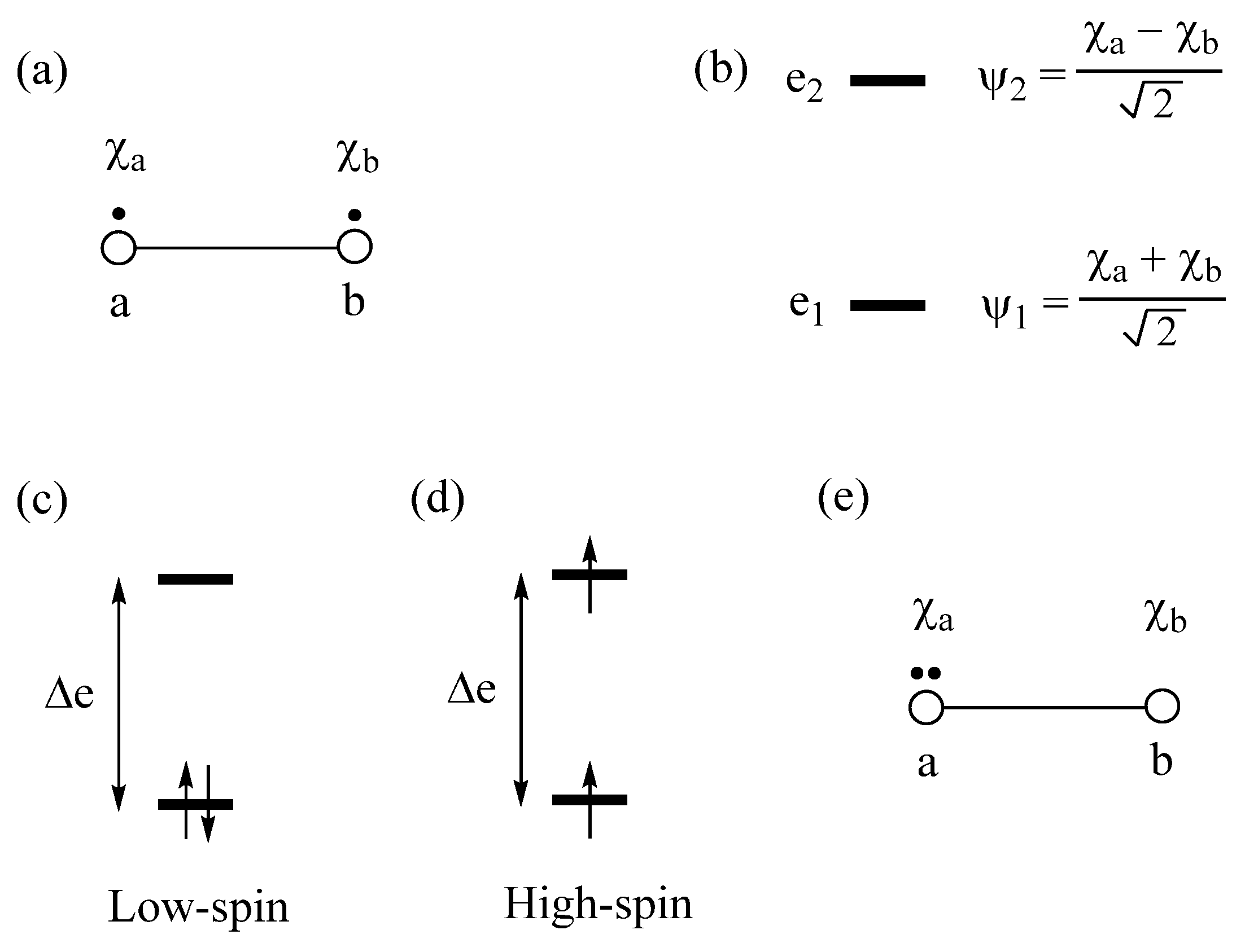
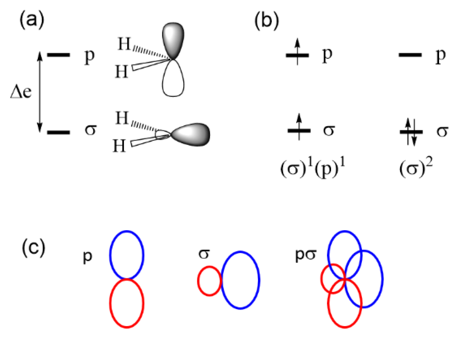
2.1. Low-Spin vs. High-Spin States

Exchange repulsions between the MOs occupied with identical spins arise from the requirement that a wavefunction be antisymmetric, affecting the predictions of the Aufbau principle. We illustrate this point by considering a dimer made up of two identical atoms, each with one AO and one electron (Figure 1a). The interaction between the two AOs, χa and χb, located at sites a and b, respectively, gives rise to the bonding molecular orbital (MO) ψ1 and the antibonding MO ψ2 (Figure 1b), separated by an energy ∆e. If t is the interaction energy (i.e., the hopping integral) between the orbitals χa and χb, then ∆e ≈ 2|t|. As long as ∆e is nonzero, the Aufbau principle predicts that the ground state is the low-spin (LS) state in which the bonding MO ψ1 is doubly occupied (Figure 1c), and that the high-spin (HS) state in which the bonding and antibonding MOs are each singly occupied with identical spin (Figure 1d) is the excited state. In terms of the orbital energy, the LS state is more stable than the HS state by ∆e. However, the two states differ in their electron–electron repulsions. The LS state has the Coulomb repulsion J11, while the HS state has the Coulomb repulsion J12 and the exchange repulsion –K12. In terms of the onsite repulsion U, namely, the electron–electron repulsion arising from the double-occupancy of one AO (Figure 1e), it is found that J11 ≈ U/2 and J12 – K12 ≈ 0. In terms of onsite repulsion, therefore, the LS state is less stable than the HS state by U/2. Consequently, the LS state is more stable than the HS state if ∆e − U/2 > 0, but the opposite is the case if ∆e − U/2 < 0 [2]. In short, the shortcoming of the Aufbau principle is corrected by introducing the concept of onsite repulsion.

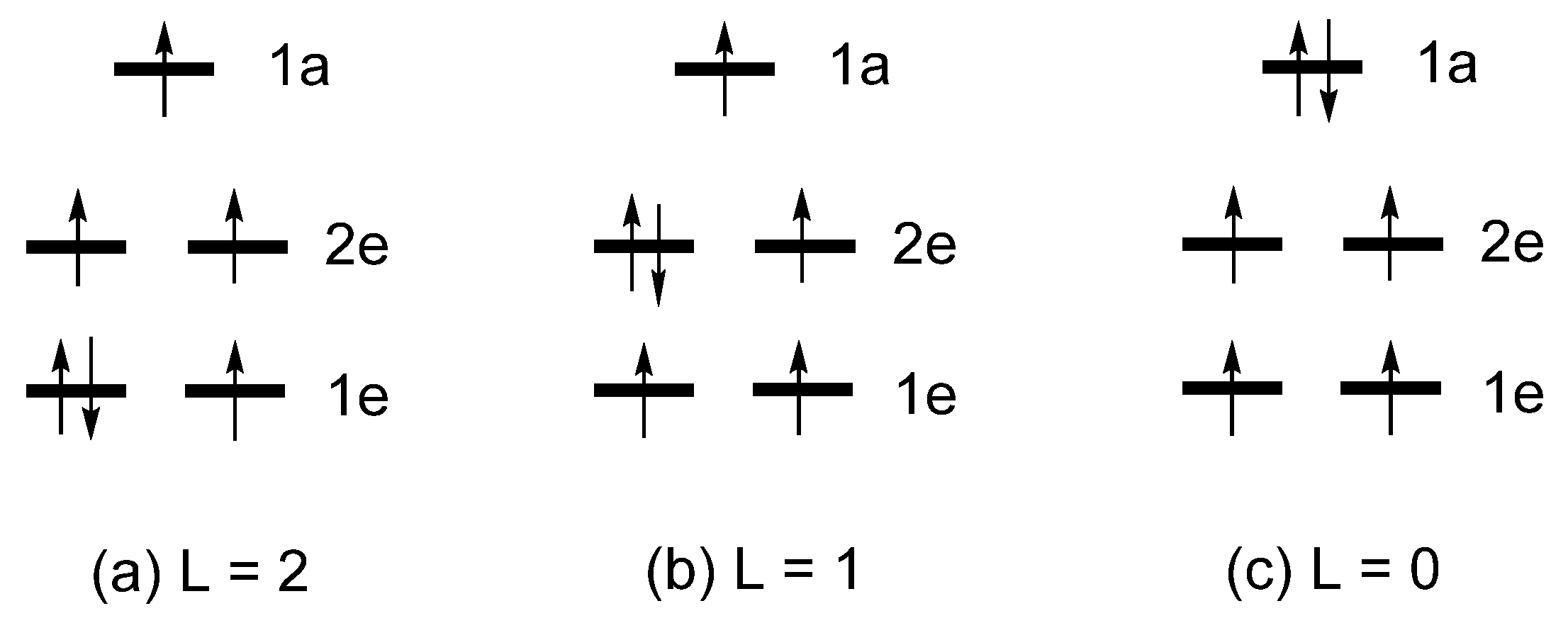
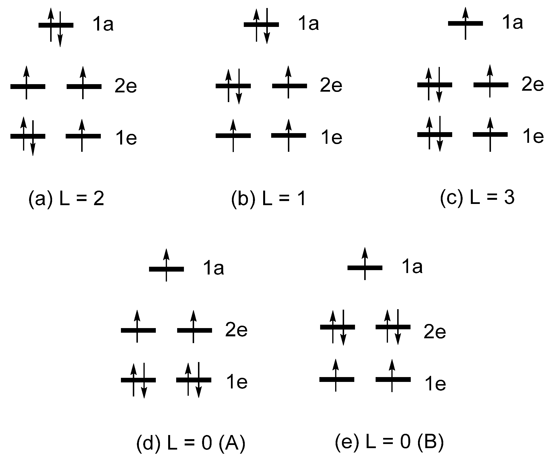
2.2. Extension of Hund’s Rule

Let us revisit the relative stabilities of the low-spin and high-spin states of a dimer, discussed above. The low-spin state ΨG with the bonding level ψ1 doubly occupied represents a singlet state and indicates that the dimer has a single bond. The high-spin state ΨT, in which the bonding level ψ1 and the antibonding level ψ2 are each singly occupied with identical spin, represents a triplet state and indicates that the dimer has neither bonding nor antibonding, in other words, the two electrons are effectively localized at each atomic center of the dimer. The excited configuration ΨE with the antibonding level ψ2 doubly occupied also represents a singlet state (Figure 2). Under the Hamiltonian H ^ that generates ΨG, the configuration ΨE interacts with ΨG, namely, the CI matrix element Ψ G | H ^ | Ψ E = K 12 is nonzero, if the Hamiltonian H ^ includes the electron–electron repulsion term. In the one-electron theory in which H ^ neglects electron–electron repulsion, there is no CI. This interaction leads to a mixing between ΨG and ΨE, leading to a singlet state lower in energy than ΨG, that is, the true ground singlet state is represented by a linear combination of ΨG and ΨE. When ∆e is small, the weights of ΨG and ΨE are comparable in the ground singlet state. If the singlet state is represented by a linear combination of ΨG and ΨE, it is found [3] that the energy difference between the singlet and the triplet states, ∆E = ES – ET is expressed as
Δ E = 2 K ab ( Δ e ) 2 U
where Kab is the exchange repulsion between the orbitals χa and χb (Figure 1a). Since Kab > 0, the triplet state is more stable than the singlet state (i.e., ∆E > 0) if ∆e = 0, i.e., when the two states ψ1 and ψ2 are degenerate. This explains the Hund’s rule. Equation (1) shows that the triplet state can be more stable than the singlet state even if the two states are nondegenerate (i.e., ∆e ≠ 0) as long as 2Kab is greater than (∆e)2/U. Equation (1) was derived for a dimer in which the AO’s χa and χb located at different sites interact weakly (Figure 1a), i.e., when the overlap integral Sab = 〈χab〉 between the AOs χa and χb is very small. Nevertheless, Equation (1) is valid even if χa and χb refer to MOs of an identical molecule with energy difference ∆e. On the basis of Equation (1), we examine two cases in which the triplet state is more stable than the singlet state, which are discussed below.
The HOMO of triplet oxygen O2 consists of two degenerate pi-antibonding MOs, πx* and πy* (Figure 3a), and there are two electrons to occupy them. The triplet state is represented by the configuration (πx*)1y*)1, and the singlet state by the linear combination of the two configurations (πx*)2 and (πy*)2 (Figure 3b). ∆e = 0 between πx* and πy* because they are degenerate, so Hund’s rule predicts that the configuration (πx*)1y*)1 is the ground state. To verify this prediction using Equation (1), we note that the exchange repulsion between πx* and πy* (corresponding to χa and χb of Equation (1), respectively) is nonzero. In general, the exchange repulsion Kab between orbitals χa and χb arises from the overlap density ρ ab = χ a χ b , namely, Kab is nonzero if ρ a b does not vanish. The overlap density πxy* between πx* and πy* involves, at each oxygen atom, the overlap density pxpy between the px and py AOs, the constituents of πx* and πy*, respectively (Figure 3a). As depicted in Figure 3c, the overlap density pxpy has nonzero regions, so the exchange repulsion between πx* and πy* is nonzero. Thus, the triplet state is more stable than the singlet state in O2 (by 22.6 kcal/mol) [4].
Now consider the singlet and triplet states of carbene CH2. The two MOs of CH2 that determine its triplet and singlet states are essentially the sp2-type orbital σ and the p orbital depicted in Figure 4a. The triplet state is represented by the configuration (σ)1(p)1, and the singlet state by the configurations (σ)2 (Figure 4b). The energy difference ∆e between σ and p is nonzero, so the Aufbau principle predicts that the singlet state is the ground state in disagreement with the experiment. Since the σ level is essentially a sp2-type hybrid orbital, the overlap density between σ and p becomes substantial (Figure 4c), and so is the associated exchange repulsion. This accounts for why the triplet state is more stable than the singlet state in carbene CH2 (by 9 kcal/mol) [5] despite the fact that ∆e is nonzero.
In short, Equation (1) extends Hund’s rule to cases involving nondegenerate levels. When ∆e is small, one needs to consider the possibility that the predictions of the Aufbau principle can be incorrect.

2.3. Limits of the One-Electron Picture

Let us consider a linear molecule FeL2 containing a high-spin Fe2+ (d6, S = 2) ion, where the ligand L is bulky, for example, L = C[Si(CH3)3]3. With the local z-axis of FeL2 taken along the axis of its rotational symmetry, i.e., along the L-Fe-L direction (Figure 5a), the five d-states, xy, x2-y2, xz, yz and 3z2-r2, of FeL2 are grouped into the 1a, 1e and 2e sets [6,7],
1a = 3z2 − r2 = |2, 0〉
1e = (xy, x2-y2) = (|2, 2〉, |2, -2〉)
2e = (xz, yz) = (|2, 1〉, |2, -1〉)
which are based on the magnetic quantum numbers lz of the spherical harmonics |l, lz〉 (l = 2, lz = ±2, ±1, 0) describing the angular properties of the d-orbitals. For simplicity, the term “d-states” are used to indicate the d-block level of FeL2 in which the d-orbitals of Fe are combined out-of-phase with s/p orbitals of the ligands L. The crystal-field theory (CFT) predicts that the d-states of a transition-metal cation at a linear coordination site are split as 1e < 2e < 1a (Figure 5b), so that the ground-state electron configuration of FeL2 containing a Fe2+ (d6, S = 2) ion is given by (1e)3(2e)2(1a)1 (Figure 6a). Consequently, the degenerate level 1e becomes unevenly occupied. A magnetic system with such an electronic configuration is predicted to have a nonzero magnetic moment only in one direction, i.e., along the z-axis. Such a magnetic system is said to be uniaxial [8]. As expected, FeL2 is found to be uniaxial [9]. Note that a system with an unevenly occupied degenerate level is susceptible to a Jahn–Teller distortion, which lowers its symmetry by lifting the degeneracy that led to the unevenly occupied degenerate level. Thus, uniaxial magnetism is observed only when the associated Jahn–Teller distortion is prevented. In FeL2, the Jahn–Teller instability is blocked by the bulky ligand L = C[Si(CH3)3]3 surrounding the Fe2+ ion [9].
Linear (FeL2) units containing a Fe+ (d7, S = 3/2) ion, found in [K(crypt-222)](FeL2), exhibit uniaxial magnetism [10]. Linear CoL2, where L = C(SiMe2ONaPh)3, contains a Co2+ (d7, S = 3/2) ion. The latter is isoelectronic with Fe+ and exhibits uniaxial magnetism [11]. In terms of the d-state split pattern of 1e < 2e < 1a explaining the uniaxial magnetism of FeL2, the ground state electron configuration of (FeL2) and CoL2 would be (1e)4(2e)2(1a)1 (Figure 6b). The latter fails to explain the uniaxial magnetism of (FeL2) and CoL2 because it has no unevenly occupied degenerate level. To explain the uniaxial magnetism of linear (FeL2) and linear CoL2 using the Aufbau principle, it was necessary to assume that the d-state split pattern is 1a < 1e < 2e (Figure 5c) [10,11] because the resulting configuration (1a)2(1e)3(2e)2 has an unevenly occupied degenerate level (Figure 6c). However, this d-state split pattern cannot explain the uniaxial magnetism of linear FeL2, because the resulting configuration (1a)2(1e)2(2e)2 for the Fe2+ (d6) ion does not have an unevenly occupied degenerate level (Figure 6d). Thus, we arrive at an impasse of the one-electron picture, as the d-state split pattern needed to explain the uniaxial magnetism of a high-spin d6 ion (d7 ion) does not explain that of the high-spin d7 ion (d6 ion) [6,7]. In terms of the CFT, the d-state split pattern of any transition metal cation at a linear coordination site is given by 1e < 2e < 1a. Thus, the Aufbau principle combined with the CFT fails to explain that of the high-spin d7 ion of linear (FeL2) and linear CoL2.
As already mentioned, the total energies of the various electron configurations of linear FeL2, (FeL2) or CoL2 are determined by the occupation of their split d-states, as well as by the Coulomb and exchange repulsions between the occupied d-states. Figure 7 depicts several electron configurations of FeL2, and Figure 8 those of (FeL2) or CoL2, where each electron configuration is classified by the value of L = i L z ( i ) , where lz(i) refers to the lz value of the occupied d-state i. The relative total energies of these configurations were examined in terms of first principles density functional theory (DFT) including extensive configuration interaction (CI) calculations [6]. These CI calculations for FeL2 show that the three states (Figure 7) increase their energies in the order, L = 2 < L = 1 < L = 0, which is exactly what the Aufbau principle predicts based on the d-state split pattern, 1e < 2e < 1a. The CI calculations for (FeL2) and CoL2 show that the five states (Figure 8) increase their energies in the order:
For (FeL2): L = 2 < L = 1 < L = 3 < L = 0 (A) < L = 0 (B)
For CoL2: L = 2 < L = 3 < L = 0 (A) < L = 0 (B) < L = 1.
With the L = 2 state as the ground state, the uniaxial magnetism of both (FeL2) and CoL2 is explained by the CI calculations. In contrast to this conclusion based on highly extensive CI calculations [6], a computational study based on CASSCF calculations [12] reported that the ground state of (CoL2)0 is the L = 3 state, but details of the CSASCF calculations were not reported. As already pointed out, the trends in the relative energies obtained by the CI calculations are not reproduced by the Aufbau principle using the d-state split pattern, 1e < 2e < 1a. If the Aufbau principle were to be combined with the d-state split pattern of 1a < 1e < 2e, the following relative stabilities can be deduced from Figure 9:
L = 2 < L = 1 < L = 3, and L = 2 < L = 0 (A) < L = 0 (B).
In short, only the ground state (i.e., the L = 2 state) correctly predicted by the Aufbau principle when combined with the d-state split pattern of 1a < 1e < 2e. As discussed above, the correct ground state for a linear ML2 system containing a high-spin d7 ion is not correctly predicted by the Aufbau principle. It is important to be aware that, though useful as a conceptual framework for discussion, the Aufbau principle can lead to such failures.

3. Effect of Onsite Repulsion on the relative Stabilities of Metallic and Magnetic Insulating States

3.1. One-Electron Approximation

The electronic structure of a molecule is described by discrete energy levels, and that of an extended solid by energy bands. For simplicity, consider a chain made up of identical atoms with one electron and one orbital per site (Figure 10a). The energy levels allowed for this chain span from the most bonding to the most antibonding levels (Figure 10b) leading to a band of width W ≈ 4|t|, where t is the hopping integral between the nearest-neighbor sites. With one electron per site, each of the lower half band levels can be doubly occupied so that there is no energy gap between the highest-occupied and the lowest-unoccupied band levels. Thus, the resulting half-occupied band represents a metallic state. In Figure 10b, each allowed level is regarded as accommodating two electrons of opposite spins. However, it is more convenient to think that each allowed level consists of up-spin and down-spin sublevels, which are degenerate in the non-spin-polarized description of electronic structures. In the latter description, the partially occupied band depicted in Figure 10b is identical to that in Figure 11a, and there is no net magnetic moment at each atomic site. In the spin-polarized description of electronic structures, the up-spin and down-spin sublevels are allowed to differ in their spatial orbitals, and hence in their energies. This will be discussed further in the next section.

3.2. Magnetic Insulating State Induced by Onsite Repulsion

When the up-spin and down-spin states of discrete molecules or extended solids become spin-polarized, more up-spin electrons occur than down-spin electrons (by convention). One outcome of the spin polarization is that both up-spin and down-spin bands can become partially occupied, as depicted in Figure 11b. This represents a metallic state in which each atomic site has nonzero magnetic moment, namely, a magnetic metallic state. When the spin polarization is strong, the up-spin and down-spin bands are completely separated so that there is an energy gap between the highest-occupied and lowest-unoccupied energy levels (Figure 11c), and the resulting state becomes a magnetic insulating state. In the metallic state (Figure 11a), each occupied state has two electrons so that the metallic state has onsite repulsion. In the magnetic insulating state (Figure 11c), all occupied states each have one electron of identical spin so that there is no onsite repulsion. Thus, when the width of the band W is greater than the onsite repulsion (i.e., when W > U), the metallic state becomes more stable than the magnetic insulating state, but the opposite is the case if W < U [2,13]. Magnetic insulators arising from the spin polarization induced by onsite repulsion are known as Mott insulators. According to the Aufbau principle, the nonmagnetic metallic state would be more stable than either the magnetic metallic state or the magnetic insulating state. The spin polarization leading to the latter two states takes place to reduce the extent of electron repulsion between occupied states.

3.3. Need to Consider beyond Onsite Repulsion

In a given group, the 3d-orbital is more contracted than the 4d orbital, which is in turn more contracted than the 5d orbital. Thus, the onsite repulsion associated with the d-orbitals is strongest for the 3d transition metal element. This is the reason why a greater number of magnetic insulators are found among the compounds of 3d transition-metal elements than among those of 4d and 5d transition-metal elements. Another factor affecting the magnitude of U of a given transition metal atom M is the charge of the atom. The d-orbitals of M are more contracted in the cation than in the neutral state, so the onsite repulsion U should be greater for the cation and should increase with an increase in the positive charge on the cation. Thus, one might consider it to be unlikely that a compound of a 5d transition-metal cation with a partially occupied band becomes a magnetic insulator.
However, this reasoning is not necessarily correct. For example, consider Ba2NaOsO6, consisting of OsO6 octahedra containing Os7+ (d1, S = 1/2) cations. The d-states of each Os7+ (d1, S = 1/2) cation are split into the t2g and eg states (Figure 12). With the p-orbitals of the surrounding ligands, the metal d-orbital makes pi-antibonding in the t2g states, and sigma-antibonding in the eg states (Figure 13). In this double-perovskite Ba2NaOsO6 [14], each OsO6 octahedron is connected to its neighboring six OsO6 octahedra by the Os-O⋅⋅⋅Na+⋅⋅⋅O-Os bridges in three orthogonal directions. Since the O⋅⋅⋅Na+⋅⋅⋅O bridges have a long the O⋅⋅⋅O contact distance (Figure 14), the t2g-states of each OsO6 octahedron interact very weakly with those of its adjacent OsO6 octahedra. To a first approximation, therefore, the xz, yz and xy states constituting the t2g set of the OsO6 octahedra form three very narrow bands. One would expect a small onsite U for the diffuse 5d orbitals, but the U for Os7+ may not be negligible because its 5d orbitals might be contracted by the high oxidation state. Since Ba2NaOsO6 is a magnetic insulator, it is most likely that the W < U condition is fulfilled for Ba2NaOsO6. This is the condition leading to Mott insulators [13]. However, this condition is not sufficient to provide a magnetic insulating state for Ba2NaOsO6 because it has one electron to occupy the three degenerate up-spin bands (Figure 15). This leads to a magnetic metallic state for Ba2NaOsO6 [14], in disagreement with the experimental observation [15]. With any value of U appropriate for Os, it is not possible to introduce a bandgap at the Fermi level. To correct his failure, it is necessary to take into consideration the effects of both SOC and onsite repulsion at the Os7+ site [14], as will be discussed in the next section.

4. Effect of Spin-Orbit Coupling

4.1. Energy of SOC

In classical mechanics, the energy of interaction between the spin and orbital moments ( S and L , respectively) of an electron in a given atom is written as ξ(r) S · L , where the constant ξ(r) decreases with the radius r of the electron moving around the nucleus, but increases with the nuclear charge of the atom because the electron density becomes more contracted, hence increasing the relativistic effect. Given the distribution of an electron, the SOC constant ξ of an atom is obtained by integrating ξ(r) over the radial wavefunction R(r) of the atom. Thus, the SOC in an atom of many unpaired electrons with total spin and orbital moments, S and L , respectively, leads to the energy [16],
λ S L
where λ = ξ /2S. For a given oxidation state, the ξ value of an element increases with increasing atomic number while, for a given element, ξ increases with increasing oxidation state. This is so because both factors lead to the contraction of electron density, hence enhancing the relativistic effect. The SOC constant λ is positive when the electron shell containing unpaired electrons is less than half-filled as in V4+ (d1, S = 1/2). When λ > 0, the lowest-energy state is obtained when S and L are antiparallel with the total moment J = L S . The constant λ is negative if the shell is more than half occupied as in Cu2+ (d9, S = 1/2). When λ < 0, the lowest-energy state results when S and L are parallel with the total moment J = L + S . If the shell is half occupied as in high-spin Mn2+ (d5, S = 5/2), SOC vanishes because L = 0 for such an ion. What matters in this discussion is only the relative orientations between S and L . Often, it is more informative to fix the coordinate system describing the orbital angular moment L and then ask how the SOC energy λ S L depends on the orientation of the spin moment S with respect to the coordinate system chosen for L . The importance of the latter approach lies in the fact that a transition-metal cation M typically forms an MLn (typically, n = 2 − 6) complex with the surrounding ligands L. Using the coordinate system (x, y, z) for L is equivalent to describing the structure of MLn using the same coordinate. By convention, the rotational axis of MLn is taken as the z-axis. This will be discussed in the next section.

4.2. Dependence of the SOC Energy on the Spin Orientation

In quantum mechanical description, the SOC energy λ S L is replaced with λ S ^ L ^ , where S ^ and L ^ are the spin and orbital momentum operators, respectively. In analyzing the SOC energy λ S ^ L ^ , it is convenient to use two independent coordinate systems (Figure 16); one coordinate system (x, y, z) for L ^ , and another coordinate system (x′, y′, z′) for S ^ . Then, the spin orientation is given by the z′-axis, which is defined by the polar angles (θ, φ) with respect to the (x, y, z) coordinate system. An important consequence of using the two independent coordinates is that the SOC energy λ S ^ L ^ is be rewritten as [16],
λ S ^ L ^ = H ^ SOC 0 + H ^ SOC
where the term H ^ SOC 0 allows the SOC interaction only between states of identical spins, and the term H ^ SOC only between states of opposite spins. The dependence of H ^ SOC 0 and H ^ SOC on the polar angle θ are expressed as
H ^ SOC 0 cos θ ( α L ^ z ) + sin θ ( β L ^ + + γ L ^ )
H ^ SOC sin θ ( α L ^ z ) + cos θ ( β L ^ + + γ L ^ )
where L ^ z is the z-component of L ^ , while L ^ + and L ^ are the raising and lowering operators defined in terms of the x- and y-components of L ^ . The constants α, β and γ depend on the angle φ, and so do the constants α′, β′ and γ′. When acted on the spherical harmonics | l , l z , these operators lead to the results.
L ^ z | l , l z     l z | l , l z   L ^ ± | l , l z     | l , l z ± 1  
That is, L ^ z does not alter the orbital character of | l , l z , but L ^ + and L ^ do. L ^ + raises the l z value by 1, and L ^ lowers the l z value by 1.
In short, Equations (5) and (6) shows explicitly how the SOC energy λ S L is affected by the orientation of the spin moment S with respect to the coordinate system describing the structure of MLn. The polar angle θ = 0° means that the spin moment is parallel to the local z-axis (||z), i.e., the rotational axis of MLn, while the angle θ = 90° means that the spin orientation is perpendicular to the z-axis (⊥z).

4.3. Magnetic Insulating State Induced by Spin-Orbit Coupling and Onsite Repulsion

We now examine how the xz, yz and xy components of the up-spin t2g state of an OsO6 octahedron are affected by the SOC. For this purpose, we note that the angular properties of the xz, yz and xy states are given by
xz | 2 , 1 | 2 , + 1 yz | 2 , 1 + | 2 , + 1 xy | 2 , 2 | 2 , + 2
and the SOC-induced interactions between them are governed by H ^ SOC 0 (Equation (5a)). According to Equation (7), the interaction matrix elements i | H ^ SOC 0 | J   ( i , j   =   xz ,   yz ,   xy ) are all nonzero. Namely, the xz, yz and xy states interact under the action of SOC, so that the three t2g levels of an Os7+ ion are split into three different states (Figure 17a) [14]. The latter leads to the three slightly overlapping bands (Figure 17b) for Ba2NaOsO6, still predicting a magnetic metallic state. Once the onsite repulsion is included, the magnetic insulating state is correctly predicted (Figure 17b) [14]. Thus, the consideration of both onsite repulsion and SOC is necessary to explain the magnetic insulating state of Ba2NaOsO6 [14]. A number of such magnetic insulators have been discovered, which are best described as spin-orbit Mott insulators [17] to distinguish them from Mott insulators.

4.4. Singlet to Triplet Transition

Let us revisit the two-orbital two-electron problem of Figure 1. If the interaction between the atomic sites is strong, the energy difference ∆e between the MOs is large. Five electron configurations are presented in Figure 18. When ∆e is large, the ground state is well represented by the singlet state ΨG, and the triplet states ΨT and Ψ′T are higher in energy. The third member of the triplet state, Ψ T , is expressed as a linear combination of Φ1 and Φ2. The alternative combination of Φ1 and Φ2 leads to the excited singlet state Ψ S . If the electron repulsions are properly taken into consideration, the
Ψ T = Φ 1 + Φ 2 2 Ψ S = Φ 1 Φ 2 2
relative energies of the ΨG, ΨT and ΨS states are given as depicted in Figure 19a [18], which shows that their energies increase in the order, ΨG < ΨT < ΨS.
In general, the ΨG state represents the ground singlet state S0 while the ΨT and ΨS states represent the first excited triplet and singlet states T1 and S1, respectively (Figure 19b). Since the singlet and triplet states differ in spin, the transition dipole moment is nonzero between the different singlet states (i.e., S0 and S1) but vanishes between the singlet and triplet states (e.g., S0 and T1). Thus, in the absence of SOC, the optical transition is allowed between the singlet states, but not between the singlet and triplet states (Figure 19b). In the presence of SOC, the singlet and triplet states (e.g., S1 and T1, respectively) interact weakly via the term H ^ SOC (Equation (6)). As a result, the true excited ‘singlet’ and excited ‘triplet’ states are not pure spin states but are mixed-spin states, namely,
S 1 S 1 + δ T 1 T 1 T 1 + δ S 1
where δ represents a small mixing coefficient. Consequently, the intersystem crossing occurs between the S1 and T1 states, and the phosphorescence takes place between the T1 and S0 states (Figure 19b).

5. Polarizability

5.1. Induced Polarization, Polarizability and Second Harmonic Generation

The dynamic polarizability of a material refers to its ability to generate instantaneous dipoles in response to an external field. With ε0 as the electric permittivity of the vacuum, the electric polarization Pi (i = x, y, z) of a material induced by the oscillating electric field Ei (i = x, y, z) of light is written as,
P i ( ω 1 ,   ω 2 , ) = P i ( 1 ) + P i ( 2 ) + =   ε 0 J = x , y , z χ i J ( 1 ) ( ω 1 ) E J ( ω 1 ) + ε 0 J , K = x , y , z χ i J K ( 2 ) ( ω 1 + ω 2 , ω 1 , ω 2 ) E J ( ω 1 ) E K ( ω 2 ) +
where χ i J ( 1 ) is the linear electric susceptibility, and χ i J K ( 2 ) is the second order electric susceptibility tensor, or the second harmonic generation (SHG) coefficient tensor when ω 1 = ω 2 . The latter is nonzero only when the system is non-centrosymmetric. Nonlinear optical (NLO) crystals are the key materials for the laser science and technology due to their ability to double the frequency of an incident laser beam through the SHG process. Over the years, a number of studies have been devoted to the understanding of which structural and electronic aspects of NLO materials govern the strengths of their SHG responses.
For an isotropic system such as an isolated atom, the linear electric susceptibility is isotropic, leading to the atom polarizability
α = P ( 1 ) ε 0 E
where P ( 1 ) and E are the magnitudes of P i ( 1 ) and Ei, respectively. In general, the polarizability of an atom becomes larger when the distribution of its valence electron density becomes more diffuse, i.e., when its size becomes larger. To a first approximation, the atoms making up a material are independently polarized so that the total polarizability Asum of the material may be given by the sum [19],
A S U m = μ α μ
where αμ is the polarizability of an atom μ in the material. In the study of piezoelectric crystals, it was shown that the second harmonic nonlinear optical susceptibility can be related to the linear susceptibility as [20],
χ i J K ( 2 ) ( 2 ω ) = χ ii ( 1 ) ( 2 ω ) χ J J ( 1 ) ( ω ) χ K K ( 1 ) ( ω ) δ i J K 2 ω
where δ ijk 2 ω is Miller’s delta parameter. For nonzero SHG coefficients χ ijk ( 2 ) , and the δ ijk 2 ω tensor does not deviate much from the mean value for all the crystals investigated despite the fact that their nonlinear susceptibilities vary over orders of magnitude. This finding indicates that an SHG coefficient χ ijk ( 2 ) has a multilinear functional dependence on the linear susceptibilities, implying that the second order nonlinear optical property can be understood from the first order property. Miller’s rule implies that a non-centrosymmetric crystal made up of atoms with high polarizability will have a large SHG response.

5.2. Polarizabilities of Cations and Anions

In interpreting the properties of a material, it is not the polarizabilities of neutral atoms but those of their cations and anions that are relevant. An atom increases its size when it becomes an anion so that its valence electron distribution becomes more diffuse, hence increasing its polarizability. The opposite occurs when an atom becomes a cation. Calculated atom polarizabilities are known for most neutral atoms [21], but hardly so for their anions and cations. Experimental atom polarizabilities are not known for many neutral atoms, and are known only for a limited few anions and cations. Therefore, it has been a challenging task to estimate the polarizabilities of anions and cations. Very recently, a practical solution to this problem has been found in the study of the 12 ABC2 (A = Zn, Cd; B = Si, Ge, Sn; C = P, As) chalcopyrites consisting of A2+, B4+ and C3− ions [18]. The SHG responses of these isostructural NLO compounds increase almost linearly with V/Eg (Figure 20), where V and Eg are the primitive unit cell volume and the bandgap of a specific ABC2 compound, respectively. In short, the larger the primitive unit cell volume, the larger the SHG response. This is understandable because the unit cell volume increases when its constituent atoms are large.
To quantify this point, it is necessary to estimate the polarizabilities of the A2+, B4+ and C3− ions. In general, the polarizability αμ for an atom μ of radius rμ is proportional to its sphere volume (4π/3)rμ3,
αμ ∝ (4π/3)rμ3.
This relationship is expected to be valid even for anions and cations. The polarizabilities of anions and cations can be estimated by employing the following four steps: (a) For the F, O2− and Cl anions, their ionic polarizabilities are known [22,23,24], and so are their ionic radii [24]. A reasonably good linear relationship exists between the two quantities [19]. (b) This linear relationship can be used to estimate the ionic polarizabilities of various ions from the known ionic radii [25]. (c) When the ionic radii of the ions (e.g., P3− and As3− anions) are unknown, we note for various ions that the polarizabilities derived from the above two steps vary almost linearly with the calculated polarizabilities of their neutral atoms [19]. (d) Finally, this linear relationship is used to estimate the polarizabilities of the ions (e.g., P3− and As3− anions) from those of their neutral atoms (i.e., P and As) [19].
Thus, for each member of the 12 ABC2 (A = Zn, Cd; B = Si, Ge, Sn; C = P, As) chalcopyrite family, we obtain the total polarizability Asum of a primitive unit cell by summing the individual ion contributions (Equation (13)). The relationship between Asum and V is linear, and so is the relationship between the SHG responses and Asum/Eg values (Figure 21). This relationship establishes a clear link between the SHG response and the first order optical response, which can be understood in terms of Miller’s rule. Notice that 12 ABC2 chalcopyrites are isostructural, so the number of atoms per primitive unit cell is identical. When we compare the SHG responses of non-isostructural NLO compounds, it is necessary to employ the Asum/Eg normalized to an identical number of atoms, for example, Asum/(NEg), where N is the number of atoms per unit cell [26].

6. Experimental Trends

6.1. Ionic Sizes and Oxidation States

It is well known that the ionic size of an element in a given group increases going down the period (e.g., from Mg2+ to Ca2+ to Sr2+). This allows one to sterically tune the structure of a compound. The ionic sizes and oxidation states of many transition-metal (TM) and rare-earth (RE) elements are relatively similar to those for many main-group elements, rendering them exchangeable within a compound. Figure 22a shows the electronegativity vs. ionic radius plot for various divalent cations at six-coordinate sites, and Figure 22b the corresponding plot for various trivalent cations at six-coordinate sites. Many divalent TM cations have ionic sizes similar to that of Mg2+, but they have higher electronegativities and possess d-electrons as valence electrons (Figure 22a). The latter provides added capabilities to tune the bonding, stability and electronic properties. Spanning the interval in ionic size between Ca2+ and Sr2+ cations are many divalent RE cations. Figure 22b reveals that the sizes of trivalent TM cations lie between those of Al3+ and In3+ (roughly between those of As3+ and Sb3+). The sizes of trivalent RE cations lie in the region between those of Tl3+ and Bi3+ (roughly between those of Y3+ and La3+).

6.2. Onsite Repulsion and d-Electron. Count

In a sense, the onsite repulsion U is a measure of how strongly its valence atomic orbitals are contracted. Thus, the onsite repulsion of an atom μ, Uμ, would increase with decreasing ionic volume Vμ = (4π/3)rμ3, and would increase with increasing oxidation state ζμ. Therefore, the onsite repulsion Uμ is expected to increase with the ratio ζμ/Vμ. Thus, to a first approximation, it may be assumed that
U μ ζ μ V μ .
An important factor affecting the ionic radius of a TM cation M at an octahedral site is how the d-states of the MLn complex are occupied. The d-states of a ML6 octahedron are split into t2g- and eg-states (Figure 12). The t2g-states are π-antibonding (Figure 13a), but the eg-states are σ-antibonding (Figure 13b), between M and L so the eg-states are more strongly antibonding than are the t2g-states. Thus, with respect to the occupation of the t2g-states, that of the eg-states lengthens the ML bond more so that the high-spin states of MLn have longer M–L bonds than the low-spin MLn. Effectively, therefore, the cation M in the high-spin state has a larger ionic radius, and hence a larger ionic volume.
Shown in Figure 23 are the plots of the d-electron count vs. the ζμ/Vμ for various divalent and trivalent TM cations in six-coordinate environments. For both divalent and trivalent TM cations, we find the following: (a) The ζμ/Vμ values for low-spin 3d cations increase as the d-electron count increases, reaching a maximum approximately at the d6 electron count. This follows the trend that, on going from left to right within a given period, the effective nuclear charge, and hence the electronegativity, increases, thereby contracting the size of the cation. (b) For a given TM cation, the ζμ/Vμ value is smaller in the high-spin than in the low-spin state, because the ionic volume becomes larger in the high-spin state due to the fact that the eg state is more antibonding than the t2g state (see Figure 13). (c) The ζμ/Vμ values for the 4d and 5d elements are smaller than those of the 3d elements, due to fact that their ionic volumes are larger. These observations are expected from our discussions on the relative stabilities of high-spin and low-spin states (see Section 2.1). (d) The effective onsite repulsion of a trivalent TM cation is greater than the corresponding divalent TM cation, because the trivalent ions are smaller in size than the corresponding divalent cations (see Figure 22).
Electronic transitions between localized (magnetic) and delocalized (metallic) states can be tuned using the above periodic trends because they can affect whether U > W or U < W. For example, the tendency toward a more metallic/delocalized behavior can be expected by substituting earlier transition metal cations into a compound (e.g., FeO to TiO in rock-salt type structures). In addition, an increase in oxidation state significantly increases the onsite repulsion by a factor of about three (e.g., Ti2+ to V3+ for the d2 electron counts), leading to more localized states. A number of TM cations at octahedral sites are susceptible to a Jahn–Teller distortion, as indicated in Figure 23. Uniaxial magnetism has been observed in the cases when the Jahn–Teller distortion is suppressed, as discussed above. Compounds containing 4d and 5d TM cations show a more metallic behavior than those containing the 3d TM cations because 4d and 5d TM cations possess a smaller onsite repulsion. The exceptional case occurs for spin-orbit Mott magnetic insulators of 5d TM cations, which arise from the combined effect of smaller onsite repulsion and stronger SOC. (see below).

6.3. Onsite Repulsion and Spin Orbit Coupling

The SOC of an atom increases with increasing the atomic number Z (i.e., approximately proportional to Z4) [27]. To examine how the onsite repulsion of TM cations are correlated with their SOC, we plot the ζμ/Vμ values of 3d, 4d and 5d TM cations against their Z values (Figure 24). In analyzing this correlation, we should note that a TM cation M with a lower coordination number has a shorter M-L distance with the ligand L because there is less steric crowding among the surrounding ligands L. That is, a TM cation M with a lower coordination number has a smaller ionic size. It is found from Figure 24 that: (a) TM cations with large ζμ/Vμ values possess high oxidation states and low coordination number (e.g., 4-coordinate Fe6+ or 4-coordinate Mn6+); (b) TM cations with large ζμ/Vμ values are found for several 3d cations, a few for 4d cations, and none for 5d cations. There are several factors leading to this trend. First, 3d cations are small in size so their coordination number can become small. This effectively shortens the metal–ligand distance M–L, hence effectively reducing the ionic size and increasing the onsite repulsion. Such an effect does not occur for 5d cations because they are large in size, and hence their coordination number cannot become small. Thus, the ζμ/Vμ value of 5d cations cannot become large by reducing their coordination number. Second, a high oxidation state is common for 5d cations because their electronegativity is low, which has the effect of increasing the onsite repulsion. The first factor dominates over the second factor (e.g., large ζμ/Vμ for 4-coordinate Fe6+ vs. small ζμ/Vμ for six-coordinate Os6+, large ζμ/Vμ for four-coordinate Mn6+ vs. small ζμ/Vμ for six-coordinate Re6+). (c) The TM cations with small ζμ/Vμ values occur for cations with high coordination numbers (i.e., six- and eight-coordination) largely because their cations are large in size. (d) For 3d, 4d and 5d cations, the ζμ/Vμ value are very small for cations with low oxidation states (i.e., below +4, not labeled in Figure 24 for clarity).
Recent experiments show that SOC effects can start to predominate in the region of Figure 24 containing Ir5+, Os5+ and Os7+ cations in octahedral coordination environments (e.g., Ba2NaOsO6 discussed in Section 3.3 and Section 4.3 [13,14] as well as other systems, such as (Na/Li)2IrO3, Sr2IrO4, NaOsO3, and Cd2Os2O7 [26]. Interestingly, this region also shows a close grouping together with Pt5+, Re5+ and Ir5+, suggesting that similar compounds with these cations in octahedral coordination environments should show strong SOC effects. The onsite repulsion can be increased or decreased by using Os6+ or W5+ cations, respectively, while maintaining a similar SOC effect. To date, however, many of these cations are not known to occur in structures with these combinations of coordination environments and oxidation states.

7. Concluding Remarks

We briefly reviewed how the onsite repulsion, spin–orbit coupling and polarizability of elements and their ions affect the physical properties of molecules and condensed materials. When combined with the energy levels generated by the one-electron theory, the Aufbau principle provides a conceptual tool with which to predict the ground state of molecules and condensed materials, although this approach can fail to provide correct predictions. In most cases, this deficiency of the Aufbau principle can be remedied by introducing onsite repulsion. For magnetic insulators of 5d transition-metal elements, termed spin–orbit Mott insulators, the consideration of both onsite repulsion and SOC is necessary in creating a bandgap. Anions and cations differ in their polarizability from their neutral analogues. Nevertheless, the polarizabilities of ions can be estimated on the basis of their ionic radii and the polarizabilities of their neutral analogues. The onsite repulsions, SOC and polarizabilities of transition metal cations are interrelated, and this interrelationship can be used to tune these parameters experimentally.

Author Contributions

The manuscript was written through contributions of all authors. All authors have read and agreed to the published version of the manuscript.

Funding

Acknowledgment is made to President’s International Fellowship Initiative of CAS (2019VMA0049);the donors of The American Chemical Society Petroleum Research Fund for partial support of this research through grant number 57882-ND10; the National Natural Science Foundation (NSF) of China (61874122, 21703251); the NSF of Fujian Province (2019J01121, 2019J05151); the Strategic Priority Research Program of the Chinese Academy of Sciences (CAS) (XDB20000000); the National Key Research and Development Program of China (2016YFB0701001); Youth Innovation Promotion of CAS (2019302); 100 talents program of CAS and Fujian Province.

Acknowledgments

MHW thanks FJIRSM for the Jiaxi Lu Foreign Guest Professorship, which allowed him to visit and carry out research collaborations at FJIRSM.

Conflicts of Interest

The authors declare no conflict of interest.

References

  1. For Comprehensive Details on the History of the Periodic Table. Available online: https://en.wikipedia.org/wiki/History_of_the_periodic_table (accessed on 30 December 2019).
  2. Whangbo, M.-H. Mott-Hubbard conditions for electron localization in the Hartree-Fock band theory. J. Chem. Phys. 1979, 70, 4963. [Google Scholar] [CrossRef]
  3. Hay, P.J.; Thibeault, J.C.; Hoffmann, R. Orbital interactions in metal dimer complexes. J. Am. Chem. Soc. 1975, 97, 4884–4899. [Google Scholar] [CrossRef]
  4. Brasseur, G.P.; Solomon, S. Aeronomy of the Middle Atmosphere: Chemistry and Physics of the Stratosphere and Mesosphere; Springer: Dordrecht, The Netherlands, 2005. [Google Scholar]
  5. Hirai, K.; Itoh, T.; Tomioka, H. Persistent triplet carbenes. Chem. Rev. 2009, 109, 3275–3332. [Google Scholar] [CrossRef] [PubMed]
  6. Koo, H.-J.; Kasapbasi, E.E.; Whitten, J.L.; Whangbo, M.-H. The conceptual dilemma of the one-electron picture in describing the uniaxial magnetism at linear coordination sites. Eur. J. Inorg. Chem. 2019, 2630–2634. [Google Scholar] [CrossRef]
  7. Whangbo, M.-H.; Xiang, H.J.; Koo, H.-J.; Gordon, E.E.; Whitten, J.L. Electronic and structural factors controlling the spin orientations of magnetic Ions. Inorg. Chem. 2019, 58, 11854–11874. [Google Scholar] [CrossRef]
  8. Dai, D.; Whangbo, M.-H. Analysis of the uniaxial magnetic properties of high-spin d6 ions at trigonal prism and linear two-coordinate sites: Uniaxial magnetic properties of Ca3Co2O6 and Fe[C(SiMe3)3]2. Inorg. Chem. 2005, 44, 4407–4414. [Google Scholar] [CrossRef]
  9. Reiff, W.M.; LaPointe, A.M.; Witten, E.H. Virtual free ion magnetism and the absence of Jahn−Teller distortion in a linear two-coordinate complex of high-spin Iron(II). J. Am. Chem. Soc. 2004, 126, 10206–10207. [Google Scholar] [CrossRef]
  10. Zadrozny, J.M.; Xiao, D.J.; Atanasov, M.; Long, G.J.; Grandjean, F.; Neese, F.; Long, J.R. Magnetic blocking in a linear iron(I) complex. Nat. Chem. 2013, 5, 577–581. [Google Scholar] [CrossRef]
  11. Bunting, P.C.; Atanasov, M.; Damgaard-Møller, E.; Perfetti, M.; Grassee, I.; Orlita, M.; Overgaard, J.; van Slageren, J.; Neese, F.; Long, J.R. A linear Co(II) complex with maximal orbital angular momentum from non-Aufbau ground state. Science 2018, 362, 1378. [Google Scholar] [CrossRef]
  12. Atanasov, M.; Aravena, D.; Suturina, E.; Bill, E.; Magana, D.; Neese, F. First principles approach to the electronic structure, magnetic anisotropy and spin relaxation in mononuclear 3d-transition metal single molecule magnets. Coord. Chem. Rev. 2015, 289–290, 177–214. [Google Scholar] [CrossRef]
  13. Mott, N.F. Metal–Insulator Transition; Taylor & Francis Ltd.: London, UK, 1974. [Google Scholar]
  14. Xiang, H.J.; Whangbo, M.-H. Cooperative effect of electron correlation and spin-orbit coupling on the electronic and magnetic properties of Ba2NaOsO6. Phys. Rev. B. 2007, 75, 052407. [Google Scholar] [CrossRef] [Green Version]
  15. Erickson, A.S.; Misra, S.; Miller, G.J.; Gupta, R.R.; Schlesinger, Z.; Harrison, W.A.; Kim, J.M.; Fisher, I.R. Ferromagnetism in the Mott Insulator Ba2NaOsO6. Phys. Rev. Lett. 2007, 99, 016404. [Google Scholar] [CrossRef] [PubMed] [Green Version]
  16. Dai, D.; Xiang, H.J.; Whangbo, M.-H. Effects of spin-orbit coupling on magnetic properties of discrete and extended magnetic systems. J. Comput. Chem. 2008, 29, 2187–2209. [Google Scholar] [CrossRef] [PubMed]
  17. Zhang, J.; Yan, D.; Yesudhas, S.; Deng, H.; Xiao, H.; Chen, B.; Sereika, R.; Yin, X.; Yi, C.; Shi, Y.; et al. Lattice frustration in spin-orbit Mott insulator Sr3Ir2O7 at high pressure. NJP Quantum Mater. 2019, 4, 23. [Google Scholar] [CrossRef] [Green Version]
  18. Albright, T.A.; Burdett, J.K.; Whangbo, M.-H. Orbital Interactions in Chemistry, 2nd ed.; Wiley: New York, NY, USA, 2013. [Google Scholar]
  19. Cheng, X.Y.; Whangbo, M.-H.; Hong, M.C.; Deng, S. Dependence of the second-harmonic generation response on the cell volume to bandgap ratio. Inorg. Chem. 2019, 58, 9572–9575. [Google Scholar] [CrossRef]
  20. Miller, R.C. Optical second harmonic generation in piezoelectric crystals. Appl. Phys. Lett. 1964, 5, 17. [Google Scholar] [CrossRef]
  21. Shannon, R.D.; Fischer, R.X. Empirical electronic polarizabilities of ions for the prediction and interpretation of refractive indices: Oxides and oxysalts. Am. Mineral. 2016, 101, 2288–2300. [Google Scholar] [CrossRef]
  22. Sadlej, A.J. Static dipole polarizability of the fluoride ion. J. Phys. Chem. 1979, 83, 1653–1957. [Google Scholar] [CrossRef]
  23. Qi, J.; Xue, D.; Ratajczak, H.; Ning, G. Electronic polarizability of the oxide ion and density of binary silicate, borate and phosphate oxide glasses. Phys. B: Condensed Matter 2004, 349, 265–269. [Google Scholar] [CrossRef]
  24. Wilson, J.N.; Curtis, R.M. Dipole polarizabilities of ions in alkali halide crystals. J. Phys. Chem. 1970, 1, 187–196. [Google Scholar] [CrossRef]
  25. Shannon, R.D. Revised effective ionic radii and systematic studies of interatomic distances in halides and chalcogenides. Acta Crystallogr. A. 1976, 32, 751–767. [Google Scholar] [CrossRef]
  26. Cheng, X.Y.; Li, Z.H.; Wu, X.-T.; Hong, M.C.; Whangbo, M.-H.; Deng, S. Key factors leading to large second harmonic generation in nonlinear optical materials. ACS Appl. Mater. Interface 2020. [Google Scholar] [CrossRef] [PubMed]
  27. Witczak-Krempa, W.; Chen, G.; Kim, Y.B.; Balents, L. Correlated quantum phenomena in the strong spin-orbit regime. Annu. Rev. Condens. Matter Phys. 2014, 5, 57–82. [Google Scholar] [CrossRef] [Green Version]
Figure 1. (a) A dimer made up of two identical atoms. The AOs at the sites a and b are labeled as χa and χb, respectively. (b) The bonding and antibonding MOs, ψ1 and ψ2, respectively, separated by energy ∆e. (c) The low-spin state of a dimer. (d) The high-spin state of a dimer. (e) The double occupation of one AO leading to the on-site repulsion U.
Molecules 25 00867 g001
Figure 2. Three configurations critical for determining the energy difference between the singlet and triplet states of a dimer. (a,b) The two singlet-state configurations. (c) The triplet-state configuration.
Molecules 25 00867 g002
Figure 3. (a) Doubly degenerate HOMO of O2. (b) Three electron configurations describing the triplet and singlet states of O2. (c) The overlap density, pxpy, resulting from the px and py orbitals at one oxygen site of O2. The positive and negative lobes of each p orbital are represented by ellipses of different colors.
Molecules 25 00867 g003
Figure 4. (a) Two MOs of carbine CH2 determining the triplet and singlet states. (b) The triplet and singlet electron configurations of CH2. (c) The overlap density, pσ, resulting from the σ and p orbitals of CH2. The positive and negative lobes of the p and σ orbitals are represented by ellipses of different colors.
Molecules 25 00867 g004
Figure 5. (a) Linear ML2 molecule, where M is a transition metal, and L a main group ligand. (b) The d-state split pattern of 1e < 2e < 1a, predicted by the crystal-field theory (CFT). (c) The d-state split pattern of 1a < 1e < 2e assumed to rationalize the uniaxial magnetism of (FeL2) and CoL2.
Molecules 25 00867 g005
Figure 6. (a, b) The high-spin d6 and d7 configurations of ML2 based on the d-state split patter of 1e < 2e < 1a. (c, d) The high-spin d6 and d7 configurations of ML2 based on the d-state split pattern of 1a < 1e < 2e.
Molecules 25 00867 g006
Figure 7. Three electron configurations of FeL2 based on the d-state split pattern of 1e < 2e < 1a: (a) L = 2, (b) L = 1 and (c) L = 0 configurations..
Molecules 25 00867 g007
Figure 8. Five electron configurations of (FeL2) and CoL2 based on the d-state split pattern of 1e < 2e < 1a: (a) L = 2, (b) L = 1, (c) L = 3, (d) L = 0 (A), and (e) L = 0 (B) configurations.
Molecules 25 00867 g008
Figure 9. Five electron configurations of (FeL2) and CoL2 based on the d-state split pattern of 1a < 1e < 2e: (a) L = 2, (b) L = 1, (c) L = 3, (d) L = 0 (A), and (e) L = 0 (B) configurations.
Molecules 25 00867 g009
Figure 10. (a) A chain made up of identical atoms with one electron and one orbital. (b) The formation of an energy band of the chain (right) from the energy level of an atom (left). With one electron per site, each level of the lower-half of the band is doubly occupied in the one-electron picture.
Molecules 25 00867 g010
Figure 11. The description of a band in terms of up-spin and down-spin subbands: (a) When the up-spin and down-spin bands are not spin-polarized, leading to a nonmagnetic metallic state. (b) When the up-spin and down-spin bands are partially spin-polarized, leading to a magnetic metallic state. (c) When the up-spin and down-spin bands are completely spin-polarized, leading to a magnetic insulating state.
Molecules 25 00867 g011
Figure 12. Transition-metal complex ML6 octahedron and its d-orbital split pattern.
Molecules 25 00867 g012
Figure 13. (a) The orbital characters of the t2g-block states of a ML6 octahedron. (b) The orbital characters of the eg-block states of a ML6 octahedron.
Molecules 25 00867 g013
Figure 14. Interaction between two adjacent t2g-states in Ba2NaOsO6.
Molecules 25 00867 g014
Figure 15. The formation of the t2g-block bands of Ba2NaOsO6 from the t2g-level of the individual OsO6 octahedra: (a) The t2g-level of an OsO6 octahedron. (b) The t2g-block bands of Ba2NaOsO6. With one electron to occupy the three degenerate up-spin bands, one obtains a magnetic metallic state.
Molecules 25 00867 g015
Figure 16. Description of the SOC in terms of two independent coordinate systems; (x, y, z) for L , and (x′, y′, z′) for S , where the z′-axis is the spin orientation.
Molecules 25 00867 g016
Figure 17. (a) The split of the t2g level of an OsO6 octahedron by the SOC of Os7+. (b) The formation of the t2g block bands of Ba2NaOsO6 from the t2g level split by the SOC, leading to a magnetic metallic state (left), which become magnetic insulating by the spin polarization arising from the on-site repulsion of Os7+ (right). Note that, under SOC, there is no distinction between up-spin and down-spin electrons.
Molecules 25 00867 g017
Figure 18. Five configurations leading to the ground and excited singlet states, as well as the excited triplet state. It is assumed that the energy difference ∆e between the two MOs ψ1 and ψ2 is large, so the ground singlet state is well approximated by ΨG.
Molecules 25 00867 g018
Figure 19. (a) The relative energies of the ground state ΨG, the excited singlet state ΨS, and the excited triplet state ΨT, where the MOs ψ1 and ψ2 used for constructing these configurations are obtained by self-consistent-field (SCF) calculations for ΨG, so e1 and e2 are the effective orbital energies including electron–electron repulsion. (b) The optical transitions associated with the ground and excited singlet and the triplet excited states. In the absence of SOC, the absorption (S0 → S1) and fluorescence (S1 → S0) are allowed, but the intersystem crossing (S1 → T1) and phosphorescence (T1 → S0) are not.
Molecules 25 00867 g019
Figure 20. The relationship between SHG (dav) and V/Eg of the 12 ABC2 (A = Zn, Cd; B = Si, Ge; C = P, As) chalcopyrites.
Molecules 25 00867 g020
Figure 21. The relationship between SHG (dav) and Asum/Eg.
Molecules 25 00867 g021
Figure 22. Plots of the crystal radii versus Pauling electronegativity of (a) divalent and (b) trivalent TM and RE cations, where the low-spin and down-spin cations are represented by shaded and unshaded circles, respectively.
Molecules 25 00867 g022aMolecules 25 00867 g022b
Figure 23. Plots of the d-electron count versus ζμ/Vμ for (a) divalent and (b) trivalent TM cations in an octahedral coordination environment, where the low-spin and high-spin cations are represented by shaded and unshaded circles, respectively. The elements in red are susceptible to a Jahn–Teller distortion or may show uniaxial magnetism.
Molecules 25 00867 g023
Figure 24. Plots of ζμ/Vμ versus the atomic number for the 3d, 4d and 5d TM cations. The coordination numbers of the cations are defined by the legends in the inset.
Molecules 25 00867 g024

