2.2. Crystal Structure Studies
Compound 3 crystallized in the monoclinic C 2/c space group with a = 19.9960(5) Å, b = 16.7246(2) Å, c = 19.1703(5) Å and β = 116.319(3)°. The unit cell has a volume of 5746.5(3) Å3, it hosts 16 molecules (Z = 16) with two symmetrically independent fragments (Z’ = 2) as basing building blocks.
The structure shows a complex network of hydrogen bonds (
Table 2) both inter- and intramolecular. The whole packing is strengthened by the presence of several
π-stacking and T-shaped interactions as reported in
Table 3 and
Table 4. According to the literature [
14], the data present in
Table 4 could suggest also a difference in “efficiency” among the different reported stacking interactions. In fact, among other criteria, the
π-stacked rings without any slippage between them are not providing the best environment for an efficient interaction among the generated quadrupoles. For this reason, although the name
π-interactions may be misleading in this case, T-shaped ones could be favored over parallel ones. The centroid 5/centroid 6 interaction (Cg (5)…Cg (6)) has not slippage reported as the dihedral angles between average planes passing from these rings falls out of the calculation cut-off. The 5-membered ring O2–N1–C5–C4–C3 shows a characteristic envelope conformation (on N1) with pucker parameters [
15,
16,
17,
18,
19] q
2 = 0.3831 Å, ɸ
2 = 42.8048°. As expected, the corresponding ring on the second independent fragment (O32–N31–C35–C34–C33) also shows an envelope conformation (on N31) as well as q
2 = 0.3838 Å and ɸ
2 = 221.4092°.
The structure shows a fairly high packing index (70%) [
20] and no residual solvent accessible voids. As a consequence, we can assume that
3 is unable to host solvents without modifying its crystal structure. It implies that the attachments of solvent molecules must take place directly from the outer part of the considered faces. This is true whatever a crystallization mechanism is considered, but not in the case of either the classical nucleation theory or the two-step mechanism [
21,
22].
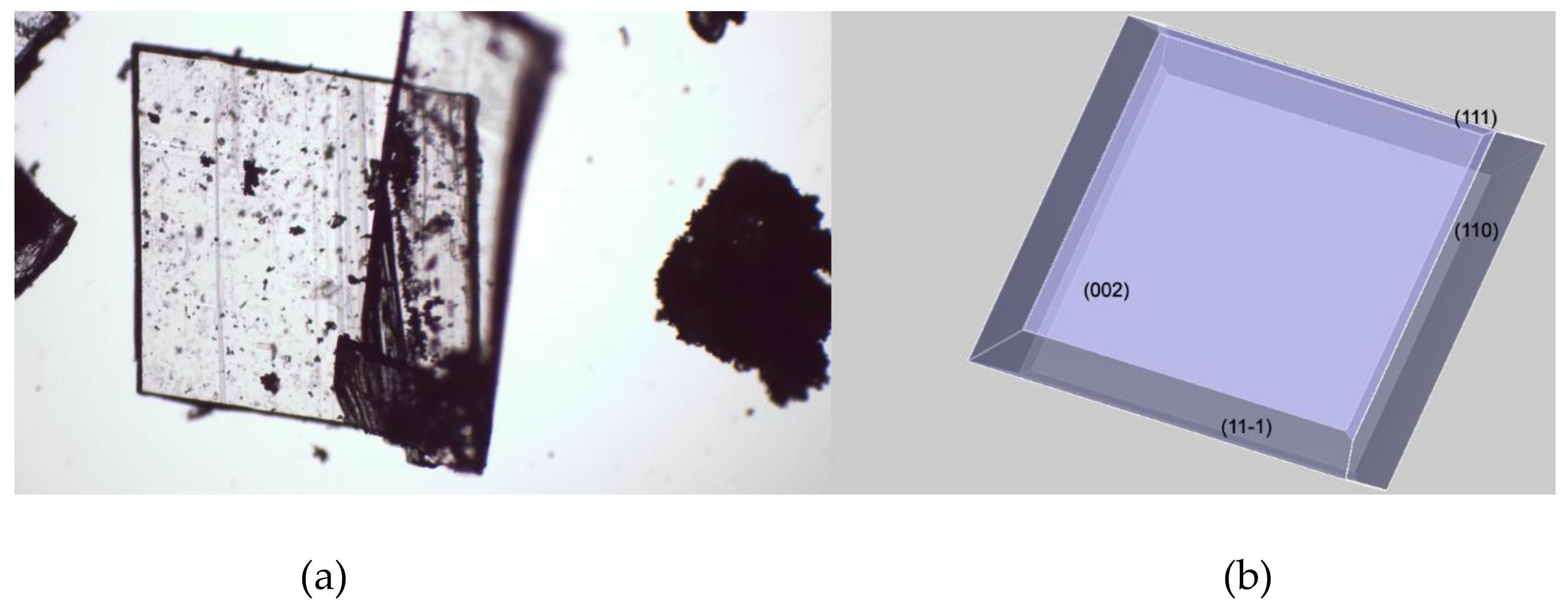
As shown in
Figure 4, there’s an extraordinary matching between the predicted crystal morphology (
Figure 4b) and the experimental one (
Figure 4a) inferred by means of optical microscopy. It is worth recalling that the crystal morphology prediction is performed in vacuum and therefore it doesn’t take into account any experimental condition such as the role of the solvents used for crystallization. This evident intrinsic limit is substantially overcome if we consider that the angle between crystal faces is controlled by the actual spacing between lattice points—which are characteristic of every considered crystal structure. According to the “law of constancy of interfacial angles” [
23], the angles between corresponding faces of the same crystal structure are always the same. This is a consequence of the symmetry of the lattice, which determines the angular relationships between faces. Thus, the experimental conditions that will affect the crystal growth can deviate the expected morphology from its ideal theoretical shape, but can’t change the angles between crystal faces, whether it is a perfect or a distorted crystal.
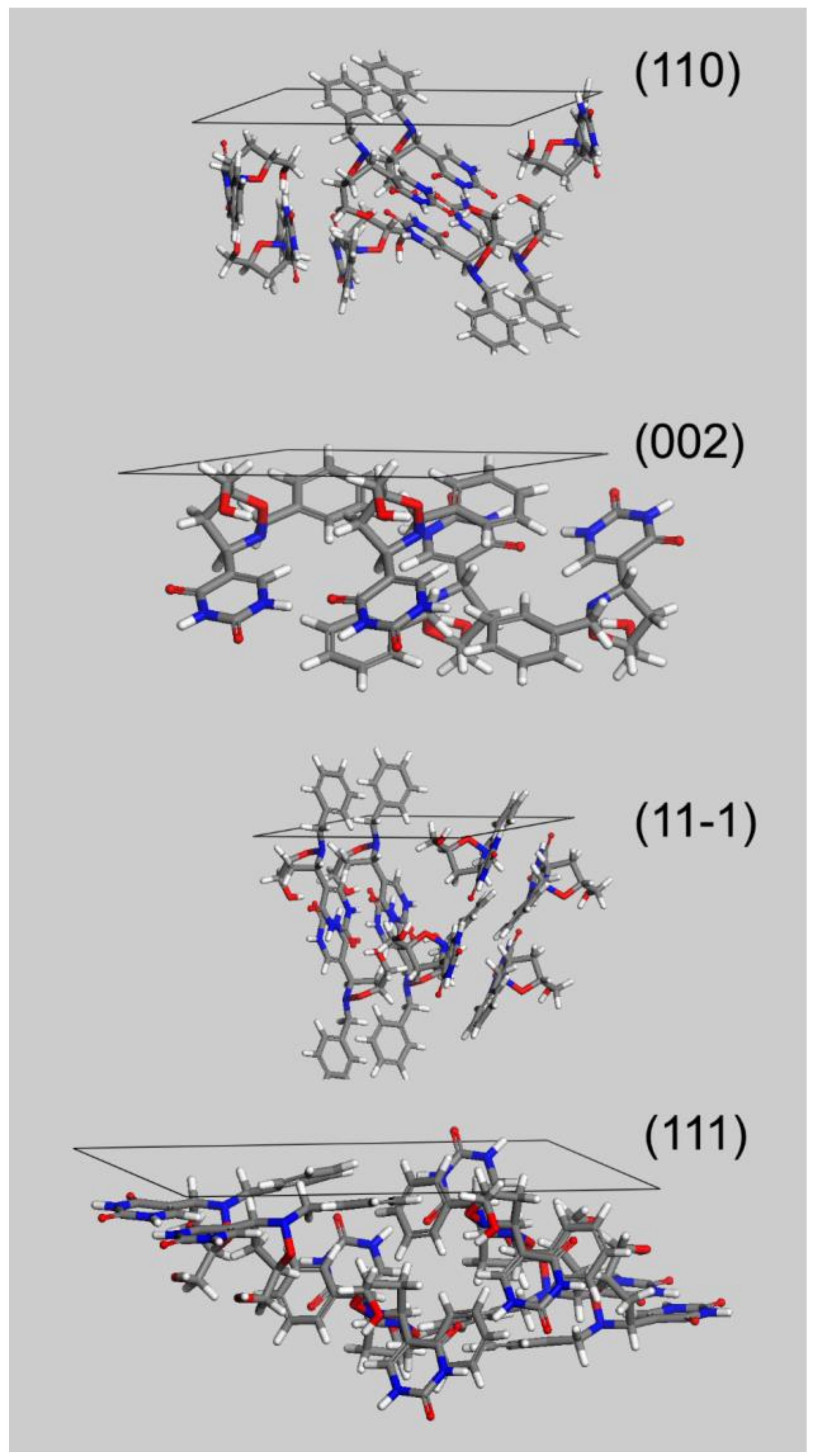
The flat and block-shaped crystals show a flat 002 face which represents, in spite of what is the visual inspection, less than the 30% of the whole crystal surface (
Table 5). The 110—and symmetry-related—faces instead is by far the most developed ones. The straight analysis of the computed crystal habit doesn’t allow any further consideration than a possible comparison with the experimentally harvested crystals. By analyzing the displacement of the crystal building blocks—i.e., the molecules—just below every single face, it is possible gaining useful information about the interactions of the crystal with different solvents. For this purpose, in
Figure 5 we report, for every MI face, the corresponding slab with the relative most protruding molecules just below its surface. This sketch will allow a qualitative analysis, mainly based on a molecule-solvent polarity affinity, which enables further consideration about the opportunity to tune the right solvent choice in order to improve or hinder crystal face growth.
Three of the MI faces show a marked non-polar environment, being (002), (11-1) and (110) all characterized by the prevalence of non-polar groups over strong polar groups. In the case of (002), there is indeed the complete lack of polar synthons. Face (111) on the other hand, while still showing an overall non-polar characteristic, evidently softens this feature as a consequence of the NH-CO-NH sequence on the 6 terms ring. This evidence gives room for speculation about the use of a different solvent mixture to enhance the growth of (111) face or, in turn, to proceed to the detriment of the other MI faces.
Solvent choice, in fact, based on its characteristics such as permittivity and volatility, is undoubtedly the major environmental perturbation potentially occurring during crystallization at room temperature and atmospheric pressure. In a computational morphology prediction, the effect of the solvent is either taken into account directly [
24,
25,
26,
27], although with some controversial results, or, as in this work, speculating about the potential solvent effects [
25,
28,
29,
30]. While electrostatic interactions among crystal molecules are expected to increase in nonpolar solvents, and decrease in more polar ones due to a shielding effect provided by the solvent itself, solvation/desolvation effects, are expected to show an opposite trend i.e., increase with increasing polarity. This is also the case when the key role in the association forces is played by π-stacking non-covalent interactions [
14].
In principle, the use of a non-polar solvent should emphasize the interaction with mostly all the MI face thus slowing the rate of their growth, which corresponds to a better and complete development of the face. In fact, it is useful recalling that the slower the growth process, the bigger and the better the face grows. An opposite situation should be experienced using a less non-polar solvent which should slacken the growth of the less non-polar (111) face thus allowing its better development. The final effect of decreasing solvent non-polarity can result in the growth enhancement of the tiny (111) and symmetry-related pinacoids thus giving rise to a thicker overall habit, such as “block” one by means of the growth of the lateral prismatic sides of the crystal. This is, therefore, another possible morphology that can be expected from the same crystal structure, without performing any dramatic change in the experimental conditions used during crystal growth.
For the above-mentioned reasoning, we can assume that, given the substantial uniformity of the non-polar environment on every considered face, the crystal morphology in presence of a non-polar solvent should be almost independent of the particular solvent used.
Furthermore, we can assume that the reported morphology is characteristic of this particular crystallographic setup i.e., cell parameters and space group [
29]. As a consequence, in case of polymorphic structures characterized by a marked difference in cell parameters, or by a different space group in which the molecules crystallize, a fast and visual discrimination can be performed, thus allowing an immediate check of the potential coexistence of different polymorphic forms.
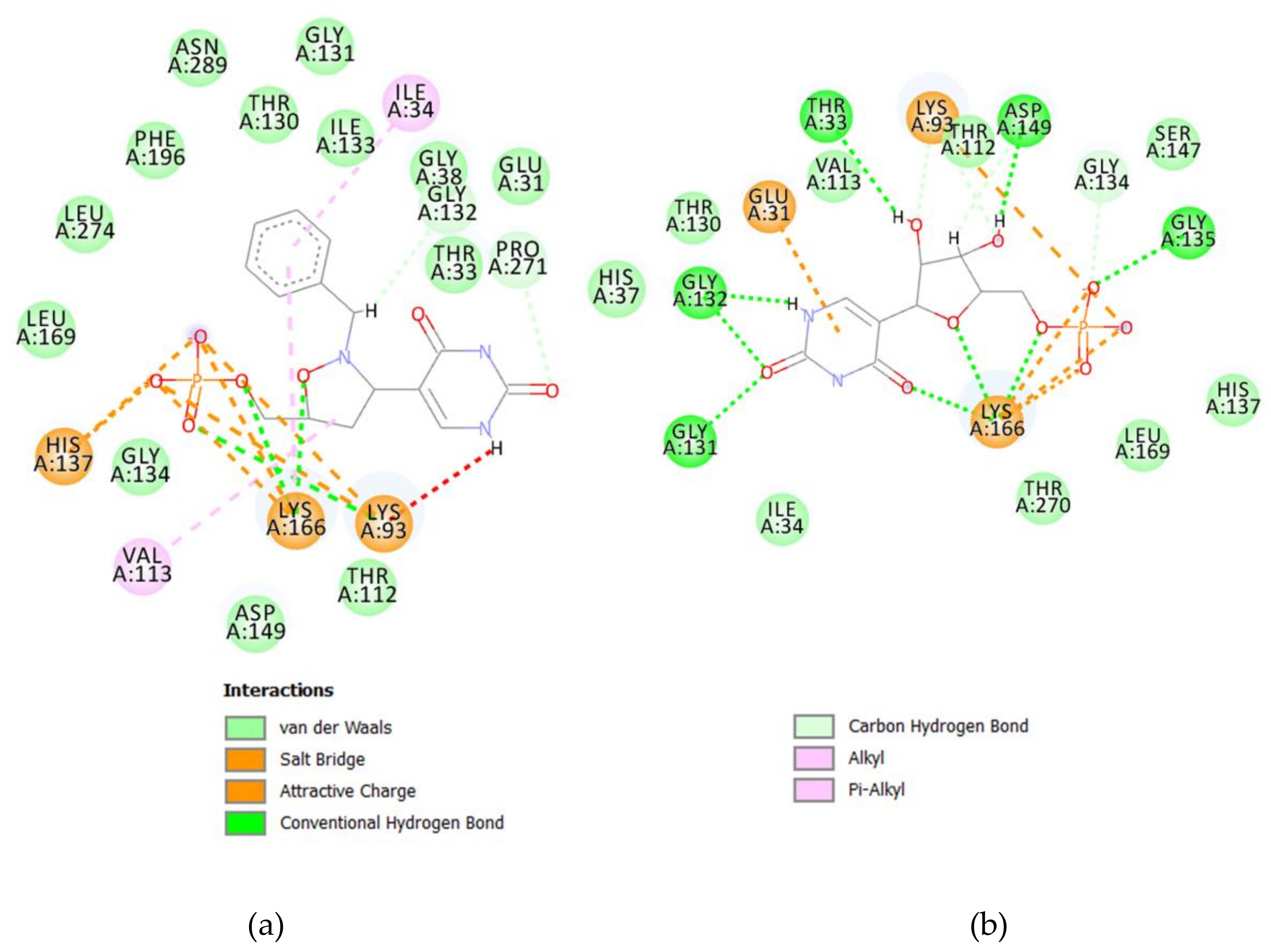
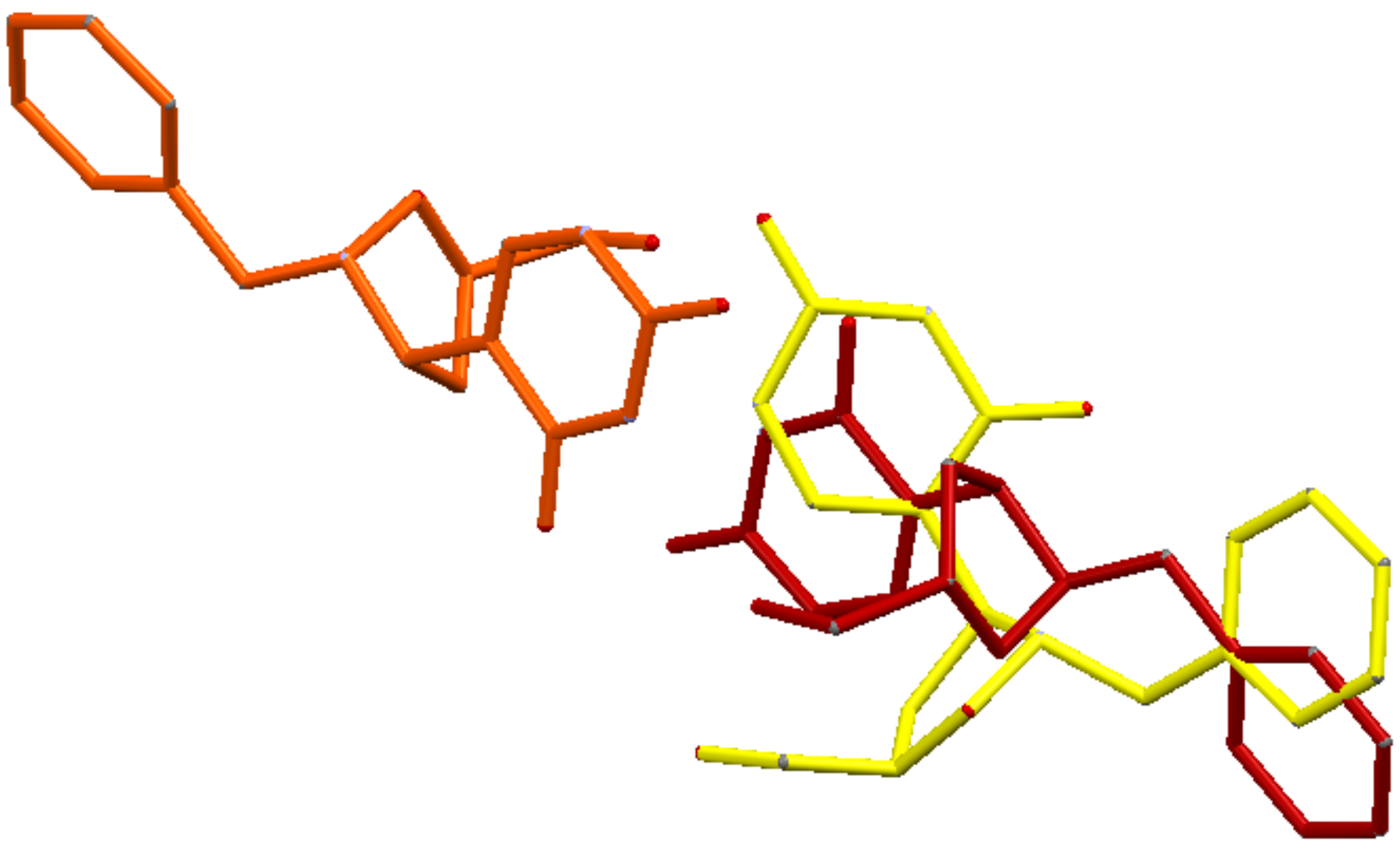
The whole crystallographic characterization allowed us to make a comparison with the molecular layout used to study potential docking features with the pseudouridine 5′-monophosphate glycosidase [
12], highlighting a marked difference as reported in
Figure 6. As expected, most of the torsional angles in the molecule backbones are significantly changed, thus suggesting a great change from the solid state structure to one which could fit in the molecular pocket of the docking target. In addition, the side rings are evidently tilted to properly fit in the pocket.
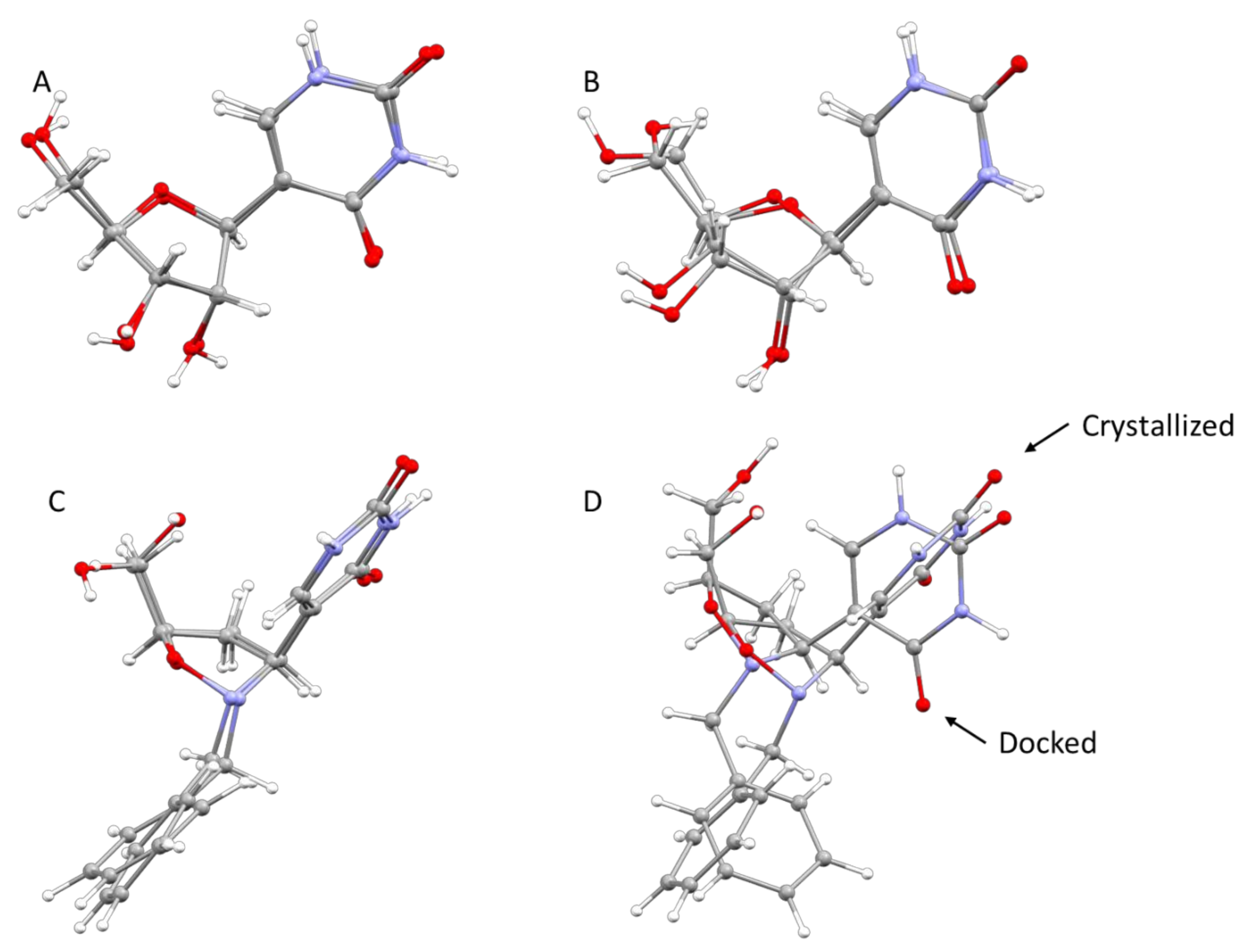
As already reported, the proposed mechanism of Ψ cleavage contemplates the acid catalyzed ribose ring opening followed by a covalent linkage between the ribose C1′ and a Ψ 5′-P Gly active site lysine 166 amino group. In light of the mechanism of the Ψ cleavage, the peculiar reactivity of the isoxazolidine ring could prevent the ring-opening process, thus inhibiting the enzyme activity, as postulated by us. The results here obtained clearly demonstrate that even the benzyl analog
3 could act as a potential inhibitor of the Ψ 5′-P Gly. Moreover, another interesting result of our modeling is that we pointed out the structure of Ψ inside Ψ 5′-P Gly, which unfortunately wasn’t obtained previously via X-ray. In fact, the only crystal structure of the enzyme with the Ψ inside the active site was the one with the K166A mutation, and according to the proposed mechanism the lysine residue is of fundamental importance and the mutant form is 2900-fold lower than that of the wild-type. In this way, our obtained “snapshot” of the docked Ψ into the Ψ 5′-P Gly could be used as a starting point for further mechanistic/modeling investigation. The comparison of MD/docking results with the crystallographic data by means of RMSD (
Table 6 and
Table 7,
Figure 7) revealed that basically, no differences between the crystallized and the docked Ψ are present. On the other hand, our compound got a higher RMSD, compared to the one of the Ψ, especially once docked inside the protein, and this was due in major part to the flip of the “uracil” ring and in part to the different accommodation of the benzyl substituent.

 ,
, 


