1. Introduction
The production of electricity from renewable primary sources is a matter that has been substantially addressed by the scientific community. Primary sources available include wind energy, which integrates most of the energy matrices in Asia, Europe, and North America [
1]. Energy conversion systems from wind kinetic energy are commonly called wind energy conversion systems (WECS). Primary sources for generating electricity, such as solar and wind, are of substantial importance in the set of renewable energies. In addition, the scientific community has invested in efforts to apply these sources efficiently, safely, and effectively [
2]. In recent years, many studies have been conducted on wind energy.
Currently, the switched reluctance generator (SRG) has been the object of study in applications with wind turbines, mainly in an attempt to increase the generator’s efficiency. This electric machine is interesting for this type of application as it presents positive characteristics, such as mechanical robustness, high efficiency, possibility of operating in a wide speed range, high power density, and is fault tolerant [
3]. In addition to being able to operate with various speed values, the SRG can be used to generate electricity without the need for a gearbox in wind turbine applications.
Several studies related to SRG are present in the literature, such as [
4,
5,
6,
7]. In Xiao [
8], some advantages of the SRG for WECS applications are presented, both for systems with gearbox and for directly coupled systems. Another way to enhance efficiency is during the design stage, as shown in [
4]. In [
6], the SRG is also presented for applications in WECS, with modeling elaborated in Matlab toolbox. As presented in [
7], the authors present the closed-loop power control using the half-bridge converter, also with the objective of generating energy from a wind turbine. In several studies it can be observed that there is concern about the efficiency of the generator associated with the wind turbine. In Toulabi [
9], efficiency is analyzed when the SRG has independent excitation and when it is self-excited.
Machine performance is usually analyzed when it is subjected to output power control. Control loops are commonly set for output current, voltage, and power. Although the power generated by the SRG can be controlled through a current loop, the power control can also be carried out by directly acting on the power generated by the SRG, as described in [
10]. The control of these quantities can be accomplished using classic controllers such as the PID. The classic controllers with proportional (P), integral (I), and derivative (D) have some advantages, such as simple structure, relative ease of design, and low cost. Nevertheless, these controllers have some disadvantages, including poor performance when its parameters are not properly adjusted, especially if the object to be controlled has nonlinearities [
2].
The generation of distributed electric energy, as well as the implementation of isolated generation systems, in regions without access to the main power grid normally makes use of primary sources such as solar and wind energy. As an example, ref. [
11] presents experimental results for validating the SRG in operation on a low-voltage DC microgrid. In these cases, it is appropriate to use generators that provide high efficiency to enhance the power generation. Considering this scenario, this paper investigates the hypothesis of associating the control of the output voltage of the SRG with a tracking technique of better efficiency with performance in the angles of switching of the power converter. This association contributes positively to the generation of energy by the SRG in variable speed scenarios, also allowing the generation of energy with low levels of generator excitation power.
Considering the previous studies developed by the scientific community on this topic, many works are noticeable related to tracking techniques applied to power maximization, as seen in [
12,
13,
14,
15]. However, this paper aims to develop an SRG output voltage control system while a tracking technique can enhance the generator’s efficiency, making it even more attractive for electricity generation from wind energy in locations without access to the main grid.
2. Theoretical Background
The switched reluctance machine is an electromechanical energy conversion equipment that has been the object of study for several years [
16]. The constructive characteristics of the switched reluctance machine basically involve a package of sheets of magnetic material for stator composition. The rotor is also laminated, so both stator and rotor have salient poles, with no brushes or slip rings. The machine is supplied with direct current via power converter. The absence of brushes on the rotor ensures greater robustness for this type of machine [
17], providing lower maintenance costs. The SRG has fault tolerance due to the independence between the magnetic fluxes of the machine phases, in addition to the phase independence also in the power converter [
18].
The absence of windings and brushes on the SRG rotor requires low starting torque. This is a positive feature for wind generation systems.
Figure 1a illustrates the cross section of a 6 × 4 topology switched reluctance machine [
19], with six poles on the stator and four poles on the rotor. A 6 × 4 topology SRG typically has three coils.
Figure 1a illustrates only one of the three coils of the machine. Other configurations related to the number of poles of the stator, rotor, and number of phases are also explored, as shown in [
20,
21].
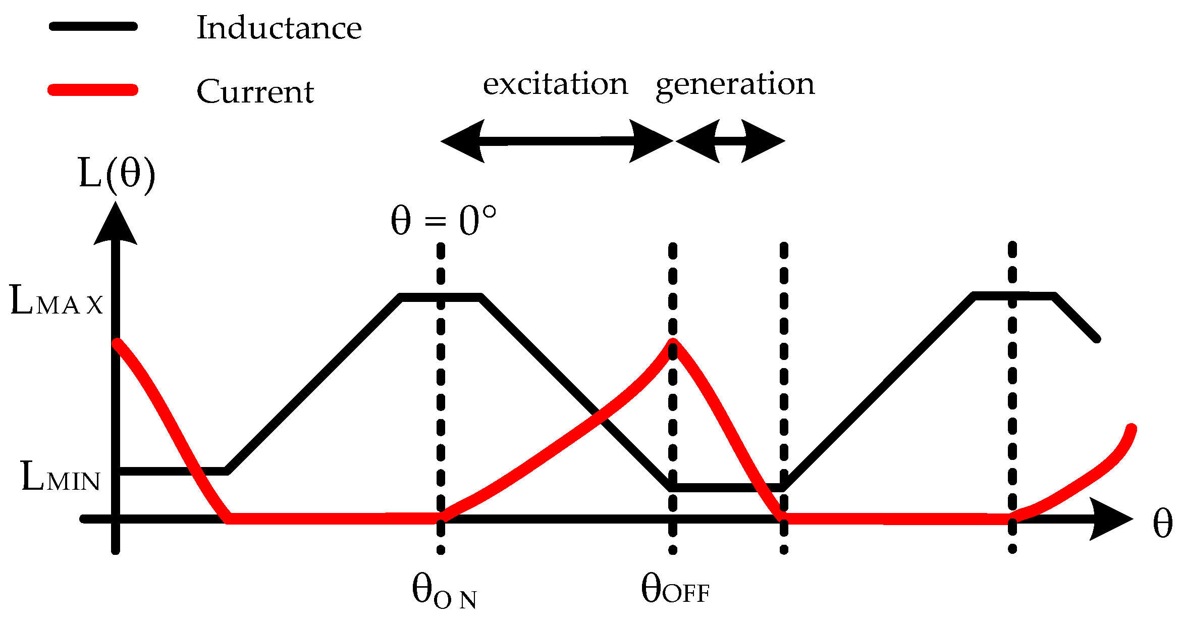
Figure 1b illustrates the behavior of the inductance of one SRG phase as a function of the angular position
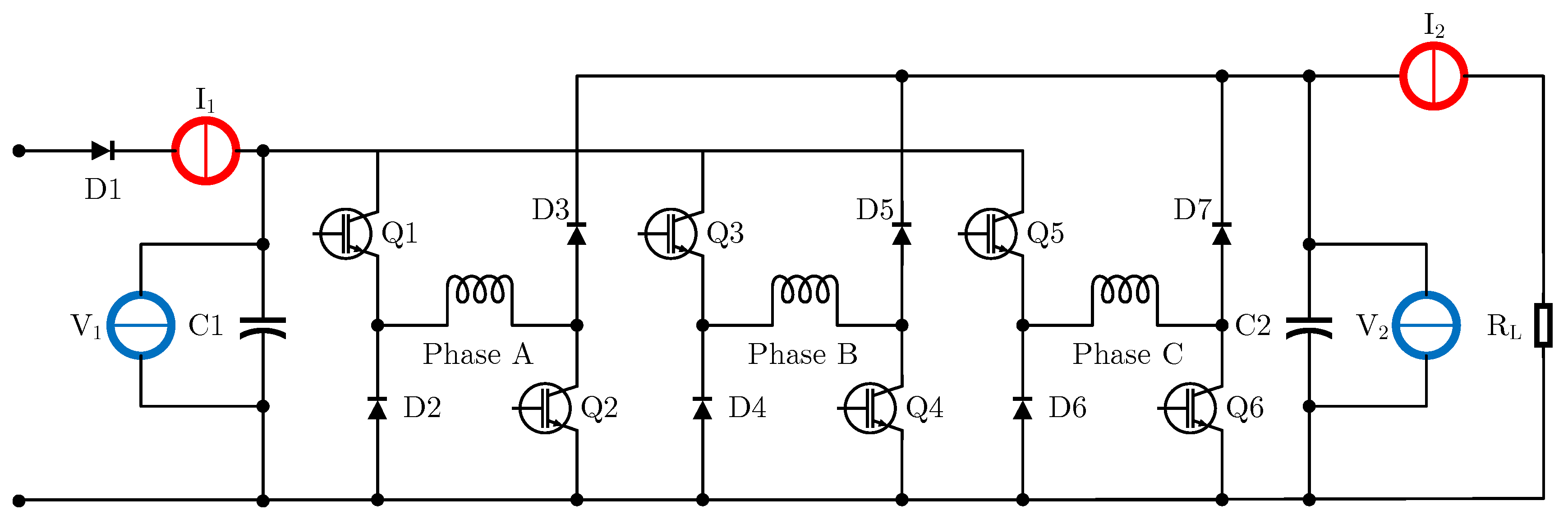
. This behavior is periodic and has the same pattern for the other two phases of the SRG. The activation of the SRG is determined by the moments in which the electric current is applied to the phase coils. Current is applied by the power converter. The most commonly used converter is the asymmetric half-bridge (AHB) converter, illustrated in
Figure 2.
In
Figure 2,
,
,
,
,
, and
are semiconductor power switches that are driven by a microprocessor system responsible for determining the machine operation. On the other hand
,
,
,
,
, and
are power diodes that allow the establishment of the path for the electric current during the regeneration stage. In
Figure 2, the position of the three coils of the
SRG is shown and the elements
,
,
, and
are measuring instruments for collecting voltage and current values for SRG input and output. The
element is the load to be supplied by the SRG and AHB converter.
The production of mechanical energy by switched reluctance machine operating as a motor or the production of electrical energy operating as a generator depends on the type of excitation provided by the AHB converter. This excitation depends on the instantaneous position of rotor , as is presented later.
2.1. Mathematical Model of the SRG
Each of the SRG coils establishes an
circuit to be powered by the excitation source
. The
circuit formed by the coil is associated with the magnetic circuit provided by the core, which can be analyzed by
where
is the resistance of each phase in ohms
,
i is the stator current in each phase in amperes
,
is the concatenated stator flux per phase in weber
and is given by
The inductance
L in henrys
depends on the instantaneous position of the rotor
, as shown in
Figure 1b and the phase current
i. Therefore, the phase voltage using (
1) and (
2) is
The last term of (
3) is the induced electromotive force
e, in volts
:
The mechanical expression is
where
is the rotor speed in radians per second
,
J is the total inertia in
, and
B is the friction coefficient in
. The electromagnetic torque
in
is obtained from
From (
6), it is possible to observe that the torque production by the switched reluctance machine depends on the current applied to the coils (independent of the direction) and the rate of change of the inductance
L as a function of the angular position
. Thus, it is necessary that the machine’s drive system has some resource that allows instantaneous measurement of the angular position
for current application to the coils during
, producing positive torque (operation as a motor), or during
, producing negative torque (operation as generator) [
22].
Figure 3 shows the current application scheme for one of the SRG coils via the AHB converter. The switching angles
and
are moments in which the power semiconductors
and
of the converter in
Figure 2 are activated, thus defining the excitation and generation steps of the SRG.
From the information presented, it is possible to observe that the output power
of the SRG depends on some factors, among them, the excitation voltage
of the AHB converter of
Figure 2 and of the switching angles
and
of the converter. Regarding these last parameters, it is expected that with appropriate excitation stage, it is possible to obtain higher values of output power
[
23].
In the scientific community there are studies related to the driving of SRG without a source of permanent excitation. This type of drive is known as a self-excitation. An example of this type of SRG operation can be seen in [
24].
2.2. Simulation Model of the SRG
Based on the SRG working theory and its mathematical model, it is possible to establish its computational model. Usually the computational model depends on the way in which coil inductance is represented, which can be linear models, mathematical models based on periodic signs [
25], or nonlinear models that consider the magnetic saturation of the core [
22].
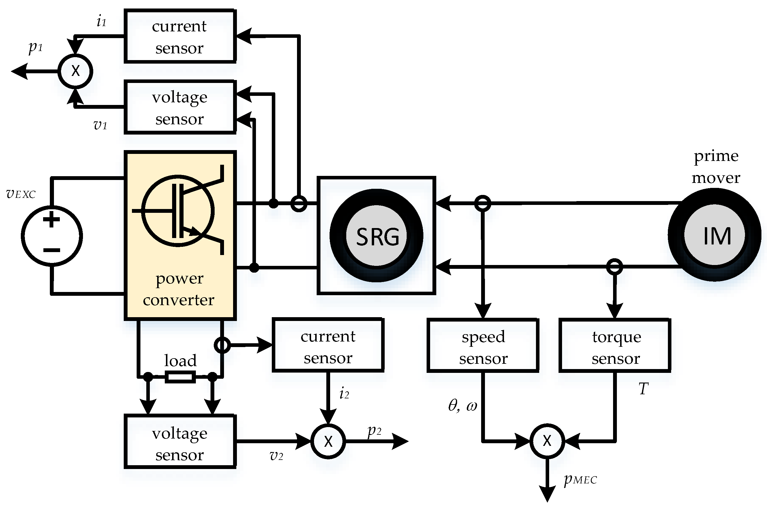
Figure 4 illustrates a diagram commonly used in SRG simulation. In the figure, IM is an induction motor that serves as the primary movement to supply mechanical energy to the SRG.
The SRG mathematical model used in this study was elaborated from
points obtained experimentally, considering the saturation of the magnetic circuit, in order to obtain an expression for the
surface using parametric regression [
22].
Measurements of electrical and mechanical quantities via sensors and instruments normally contribute to the evaluation of SRG efficiency, obtained by
where
is the electrical output power,
is the electrical excitation power, and
is the mechanical input power, all of them in watts
. The mechanical power is given as the product between the rotor speed, in
, and the torque, in
.
In this study, the nonlinear model of the coil inductance was used, considering the saturation of the magnetic core of the generator, as performed by Araujo [
22].
Parameters commonly analyzed in the simulations are values that represent the performance of the SRG. In addition to the electrical, mechanical, and generator efficiency, other parameters can be analyzed, such as torque ripple, vibration, heating, and other parameters that, when necessary, resort to the application of the finite element method [
26].
3. Methodology
Considering that the SRG is a DC generator, its output is normally used in alternating current conversion systems, such as inverters or charge controllers. In these cases, there is usually a need to control the generator output voltage to suit these conversion systems. Therefore, in this study, a voltage PID controller is designed and applied to the SRG output.
Thus, the output voltage is the variable controlled by the PID. However, as shown in
Figure 5, in this paper the controller is evaluated considering some manipulated variables, such as excitation voltage
, the turn-on angle of activation of the power converter (
), and the turn-off angle of the power converter (
).
Manipulating excitation voltage
of the SRG power converter provides control of its output voltage. On the other hand, the manipulation of the switching angles
and
of the power converter allows adjustment of the excitation window, as shown in
Figure 3, which also contributes to changing the values of the output voltage. In other words, the
and
values allow adjusting the SRG excitation time before the generation period.
Thus, in this article, three case studies are established for the SRG operating at variable speed:
Analysis of the turn-on angle influence on the generator behavior, in order to establish a suitable value for use in the other stages of the methodology.
Optimization of the PID controller for the SRG output voltage and analysis of the generator behavior when the manipulated variable is the excitation voltage and when it is the turn-off angle of phases .
Development of an algorithm to implement a technique for tracking the maximum generator efficiency associated with the output voltage PID controller.
The PID controller has a linear characteristic and is a controller that has only one output. Thus, it is expected that the use of the maximum efficiency tracker in parallel with the controller can positively contribute to the SRG efficiency. Therefore, the last step of the methodology carries out this study for this verification.
With the results of these methodologies in mind, it is expected that the SRG can be activated and controlled in order to provide better performance for wind energy applications, resulting in lower excitation power, better efficiency, and lower levels of mechanical vibration.
3.1. Case Study I—Analysis of the Influence of Turn-On Angle on SRG Performance
As can be seen in
Figure 3, normally, the electronic switches of the power converter of
Figure 2, for each of the phases, are energized when the inductance of the respective phase is maximum, at which point the instantaneous angle
is considered null (
). At this point, the generator excitation step begins. When the switches of the respective phase are turned off, the generation step begins. Therefore, the size of the generation window determines the behavior of the SRG with respect to the output voltage, efficiency, and torque ripple.
For
topology reluctance machines, the literature usually establishes that the most suitable conduction window is 30 degrees [
25,
27], i.e.,
However, at this stage of the methodology, a study was carried out to determine if this conduction window, even maintained at , can positively contribute to the generator’s performance if it is anticipated for angles smaller than .
In this way, the computational model was subjected to several iterations so that the turn-on angle was varied from
to
degrees while the conduction window was kept fixed at
, respecting Equation (
8).
For analysis purposes, the generator was simulated in open loop in this methodology, with fixed excitation around . The speed was also kept fixed at = 1000 rpm.
The interest in this stage, as explained above, is to analyze the generator’s behavior. The main parameters used as a metric in this step are the output power
, the efficiency of the generator, shown in Equation (
7), and the torque ripple. Several studies on the reluctance machines are concentrated in the attempt to minimize the torque ripple, as presented in [
14], where an artificial neural controller is applied to minimize the torque ripple and to maximize the power of the SRG. This process is appropriate because the oscillatory nature of this type of electric machine makes the vibrations greater when compared to other types of machines. Therefore, minimizing the torque ripple can contribute positively above all, with wind generation systems, as also presented in [
28].
In this methodology, the torque ripple was observed for each iteration of
using the equation
where
is the rms value of the electromagnetic torque in Equations (
5) and (
6), and
is the average value of this same quantity, both measured in
.
3.2. Case Study II—PID Controller Optimization and Performance Analysis for Different Manipulated Variables
As illustrated in
Figure 5, the SRG is excited with a DC voltage
from a fully controlled three-phase AC–DC converter. The system controller acts on the firing angle of the AC–DC converter, providing control of the generator excitation.
On the other hand, the system controller obtains the instantaneous position of the rotor through a rotary encoder, being able to modify the values of the excitation window for the power converter. However, the value will be kept fixed according to the result obtained in the previous methodology.
Therefore, in this step it is appropriate to check which manipulated variable provides the best contribution to the system’s performance when submitted to a closed-loop output voltage control: the excitation voltage or the turn-off angle .
In this way, a PID controller was implemented for the generator output voltage
, acting on the excitation voltage
. The switching angles of the power converter were kept fixed, so that
assumed the value found in the previous methodology and the excitation window was kept fixed at
, according to Equation (
8). For this configuration, the controller was subjected to various setpoint values in the range from 50 V to 180 V, in 10 V intervals. For each setpoint value, the rotor speed was adjusted from 500 rpm to 1800 rpm, in intervals of 100 rpm.
Then, the manipulated variable by the PID controller was changed to the turn-off angle . In this case, the excitation voltage was kept fixed at the generator nominal voltage ( = 180 V) and the turn-on angle was kept fixed at the value found in the previous methodology. However, in this case, the controller acts on the turn-on angle of the power converter to affect the control of the output voltage. Likewise, the voltage PID controller was subjected to various setpoint values in the range from 50 V to 180 V, in 10 V intervals. Again, for each setpoint value, the simulation was performed by varying the generator speed from 500 rpm to 1800 rpm, in 100 rpm intervals.
These two tests for the two manipulated variables have, as main objectives, to evaluate both the performance of the controller and the generator. The metric used for this evaluation is the capacity of the controller to control the output voltage, the generator efficiency, and the torque ripple under setpoint variations and disturbances.
For both tests, the gains of the PID controller were adjusted using an optimization process.
The parameters of the voltage controller are the proportional gain
, the integral gain
, and the derivative gain
. The tuning of these parameters can be carried out considering several methods already presented by the scientific community. In this work, the adjustment of
,
, and
is carried out using a hybrid optimization process, combining the quasi-Newton method (QNM) and the genetic algorithm (GA). The optimization process applied to the adjustment of the PID controller parameters is advantageous, as the obtained values can be applied with variation of parameters such as the setpoint, load insertion, and speed variation [
29].
In this way, the optimization process employed tests various values for the parameters of the PID controller with the following fitness function:
This fitness function was used to evaluate the controller performance for the
,
, and
parameters at each iteration of the process until the stop criterion is reached. In Equation (
10),
is the instant that output voltage
has a maximum value in
t. The Expression (
10) evaluates the partial results of the optimization process considering three factors: (i) the integral of absolute error (IAE), (ii) the percentage of overshoot of the output voltage (
), and (iii) the error in steady state of the output voltage (
). These three values are normalized in relation to the generator output (
).
The optimization process guarantees satisfactory response for the control system. In this process, the parameters , , and can even be updated by the optimization process, which can lead to controllers without one of the actions, such as (i) P, (ii) PI, (iii) PD, or (iv) PID. With the appropriate parameters provided by the optimization process, the PID controller is then tuned to these values. To validate the controller performance, tests must be performed with variation of the setpoint and with disturbance in the output variable (). The efficiency tracking technique is then applied.
3.3. Case Study III—Development of Maximum Efficiency Tracking Technique Associated with the PID Controller
As previously explained, electric machines used in isolated or distributed generation systems are machines that should, as far as possible, have high efficiency. As the focus of this work is on SRG efficiency for these scenarios, an efficiency tracking technique was developed. As well as techniques for tracking the maximum power point (MPPT) used in various energy systems, in this case, a perturb-and-observe algorithm is employed, but with a focus on generator efficiency instead of power. Therefore, a maximum efficiency point tracking technique (MEPT) is established here.
The MEPT technique developed in this work acts in parallel with the PID controller of the generator output voltage. In this case, the advantage is the possibility of acting on more than one variable simultaneously, which would not be possible only with a linear controller such as the PID. The MEPT tracking Algorithm 1 is shown as follows.
| Algorithm 1: Maximum Efficiency Point Tracking (MEPT) algorithm |
 |
As can be seen, the MEPT algorithm initially waits for the PID controller to act. This means that the tracking is only started when the output voltage reaches the steady state, assuming the value indicated in the setpoint with a margin of error of . Then, the conduction window defined by the values of the and angles (initially set at and , respectively), begins to be left-shifted so that the angle assumes, at most, the value found in the first methodology.
When
value reaches the appropriate value, according to the first phase of the methodology, a perturb-and-observe technique is implemented; therefore, the
angle is decreased as a disturbance and the efficiency value is observed. The purpose of this procedure is to reduce the size of the conduction window of Expression (
8) so that the excitation power of the SRG is reduced, contributing positively to the efficiency indicated in Expression (
7).
In this way, the MEPT algorithm allows achieving better values of efficiency for the generator in parallel to the PID control of the output voltage, as the MEPT acts only while the permanent regime is reached. This means that the algorithm does not allow the disturbance in values to negatively influence the performance of the PID controller.
4. Results
As explained in one of the methodology sections of this study, the SRG was subjected to three stages of tests to assess the influence of the turn-on angle on the parameters: output power , efficiency , and torque ripple . This first stage, in addition to providing an analysis of SRG performance based on established metrics, provides for the other stages of the methodology to operate with a more favorable value. In sequence, the optimization of a voltage PID controller with actuation in (i) excitation voltage and (ii) the turn-off angle was performed. Finally, an algorithm with maximum efficiency tracking technique was developed and applied in parallel to the voltage PID controller to evaluate the final results.
The methods used in this study were performed considering a switched reluctance machine with
topology, with parameters shown in
Table 1.
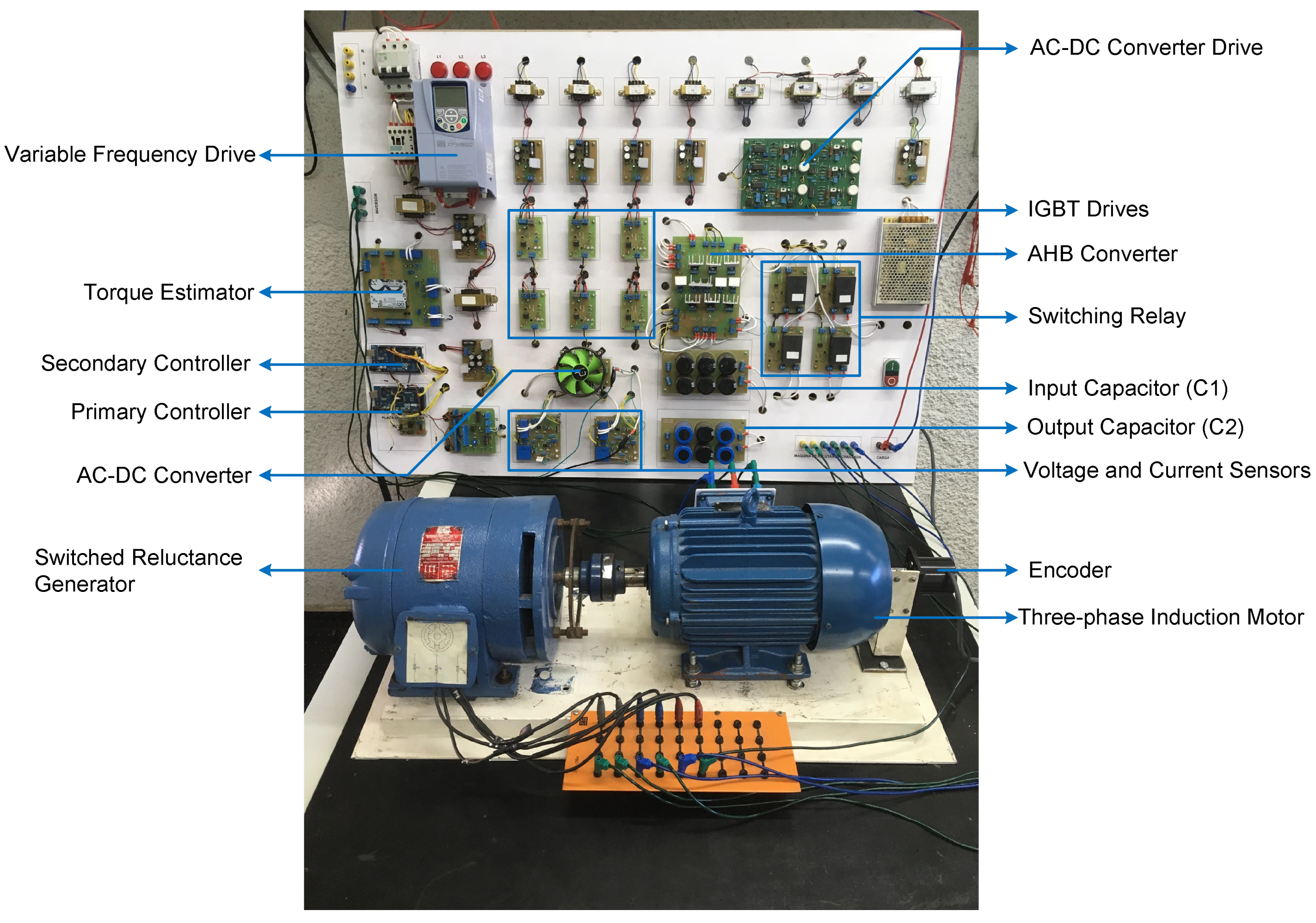
For all tests developed in this study, a purely resistive load with a value of was used. In some cases, the load resistance was varied in order to promote a disturbance in the system, in order to evaluate the performance of the voltage controller.
Figure 6 presents the experimental platform developed to evaluate the results.
4.1. Case Study I—Analysis of the Influence of Turn-On Angle on SRG Performance
This stage of the study assesses the influence of turn-on angle
on SRG performance. All tests of this stage were performed in open loop with fixed excitation and speed of 1000 rpm.
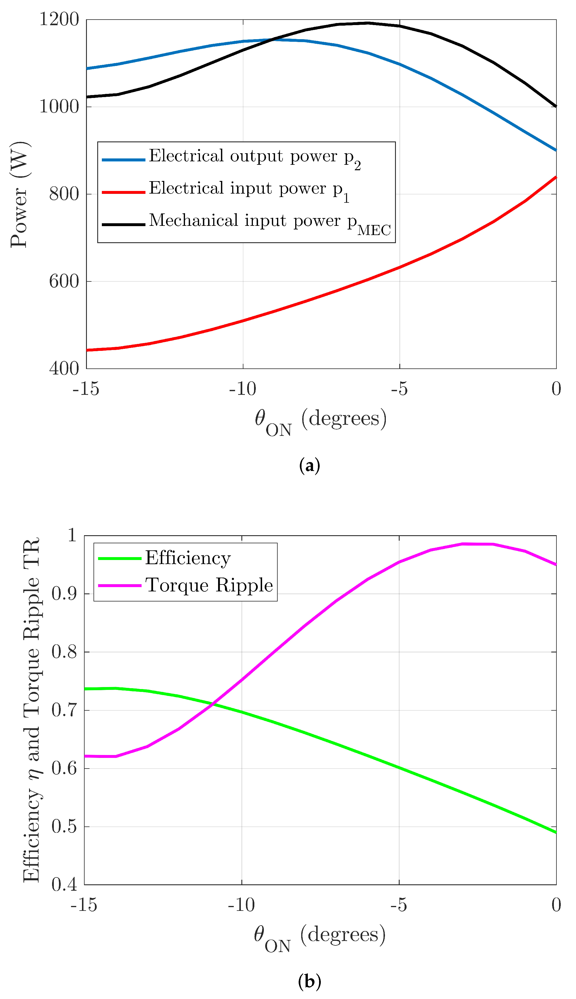
Figure 7a illustrates the electrical output power (output power
), the electrical input power (excitation power
), and the mechanical input power (
), and
Figure 7b illustrates the SRG efficiency
and the torque ripple
.
Analyzing
Figure 7a, it is appropriate to adopt as a metric a value of
that provides greater power generated at the output, while both the electrical and mechanical input powers are the lowest, favoring the enhancement of efficiency, as shown in Equation (
7). For the results shown in
Figure 7a,
value is presented as favorable for this case.
On the other hand, in
Figure 7b, it is interesting to note a
value that provides higher efficiency values and lower torque ripple values, favoring the minimization of the generator’s mechanical vibrations. Likewise, in
Figure 7b, the
value is presented as suitable for this metric.
In this way, the value is considered for the later stages of the methodology of this study.
4.2. Case Study II—PID Controller Optimization and Performance Analysis for Different Manipulated Variables
In this stage of the study, the PID controllers for the SRG output voltage were optimized in order to obtain proportional, integral, and derivative gains (, , and ), both for the controller acting on the excitation voltage and the controller acting on the turn-off angle .
The optimization method employed is hybrid, as it mixes heuristic and deterministic techniques in the search for the best values. The genetic algorithm, used as a heuristic technique, was configured with the following characteristics: population of 20 individuals, 100 generation stop criteria, uniform mutation, selection by tournament, and heuristic crossover. The stopping criterion for iterations involves the maximum number of generations or when the fitness function represented by Equation (
10) reaches zero.
The parameters found by the optimization method were = 84.04 · 10°/V, = 512.77 · 10°/V, and = 2.146 · 10°/V for the voltage PID controller that acts on the excitation voltage of the SRG. For the PID controller operating on the turn-off angle, the parameters obtained were = 42.86 · 10°/V, = 297.94 · 10°/V, and = 758.56 · 10°/V.
Figure 8a,b present simulation and experimental results for the control of the SRG output voltage using the excitation voltage V1 as manipulated variable.
For both results, a load disturbance was applied at time . The load initially has a value of 50.6 , and at t = 8 s it is instantly changed to 32.9 .
More tests were performed, but with the setpoint adjusted to 100 V and 120 V, as shown in
Figure 9 and
Figure 10.
In order to more broadly assess the behavior of the SRG with the aforementioned controllers, simulations were performed varying the setpoint and the speed of the generator.
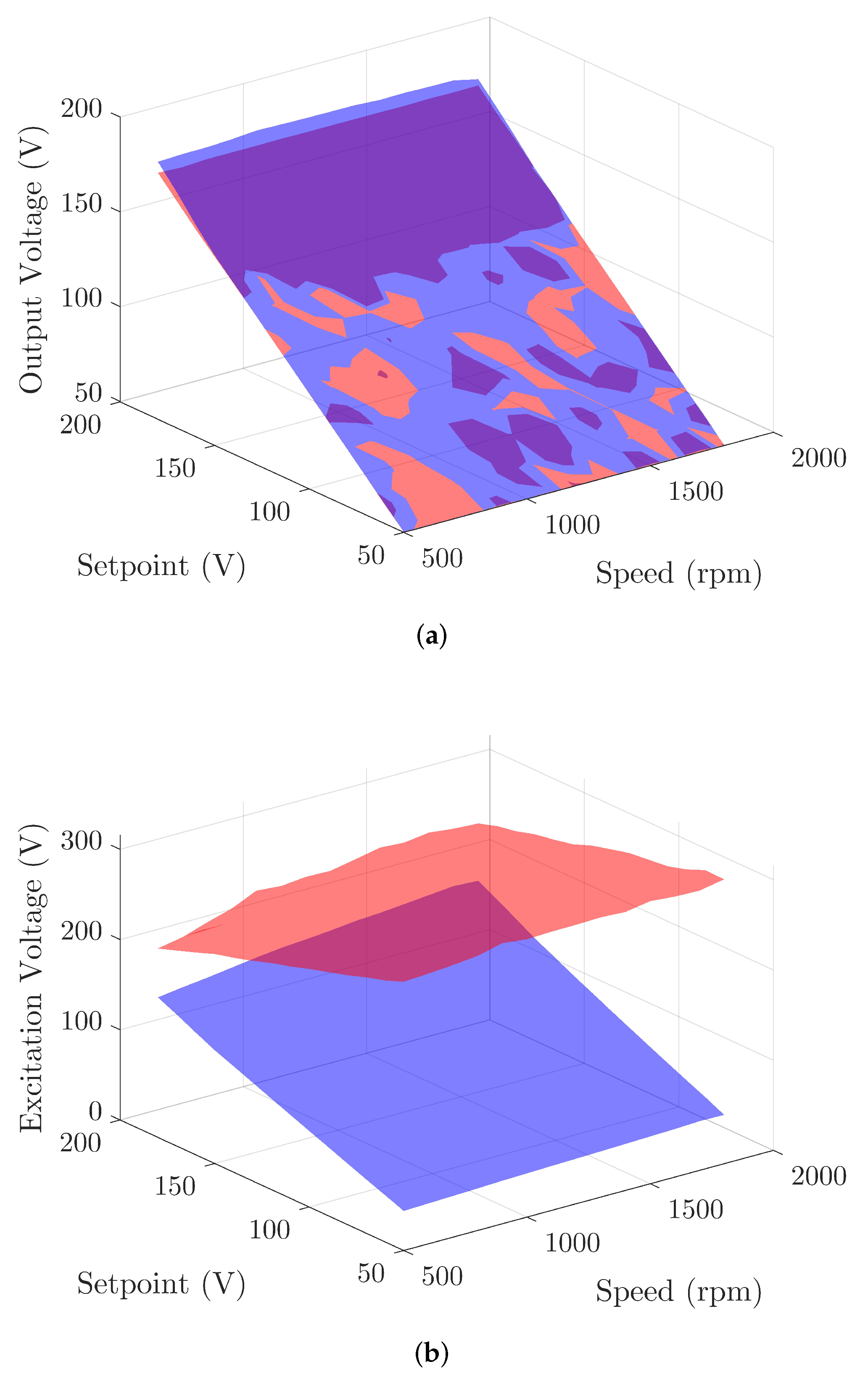
Figure 11a,b and
Figure 12a,b illustrate the surfaces, for each simulated PID controller, of the output voltage
, excitation voltage
, efficiency
, and torque ripple
. For these figures, the blue surfaces are related to the PID controller acting on the excitation voltage and the red surfaces are related to the PID controller acting on the turn-off angle. To obtain the surfaces, both controllers were subjected to variations in the setpoint, in the 50 V ≤ setpoint ≤ 180 V range. The rotor speed was also varied in range 500 rpm ≤
≤ 1800 rpm.
Analyzing
Figure 11a, it is possible to verify that the performance of both controllers is satisfactory, as the surfaces of
Figure 11a present an angle of approximately
between the
y axes (setpoint) and
z (output voltage). Therefore, the controllers provided the same values in the setpoint at the output, with low error values in steady state. In addition, it is possible to verify that the parameters found for the controllers via optimization process contribute positively when the generator speed is modified, which is an appropriate result for wind generation scenarios.
On the other hand, as previously shown, in
Figure 11b it is possible to verify that the PID controller that operates at the turn-off angle applies high voltages in the generator’s DC bus, exceeding even the nominal value shown in
Table 1.
Regarding the performance of the SRG when subjected to voltage PID controllers, it is desirable that the efficiency of the generator is as high as possible and that the torque ripple is as low as possible. However, in
Figure 12a,b, it can be seen that the controller that acts on the turn-off angle causes the generator to present more favorable results. However, as previously presented, this type of controller has the drawback of the need for high excitation voltages for its correct operation. Therefore, the strategy at this point in the research is to develop some technique parallel to the PID controller that acts on the excitation voltage so that the efficiency and torque ripple metrics can be improved in relation to the results presented in
Figure 12a,b. This technique is presented in the next section.
4.3. Case Study III—Development of Maximum Efficiency Tracking Technique Associated with the PID Controller
As previously explained, it is desired in this study that the PID controller that acts on the SRG excitation voltage be used, in view of some disadvantages presented by the PID controller that acts at the turn-off angle. However, in an attempt to improve the performance of the PID controller that acts on the generator excitation, a maximum efficiency point tracking algorithm was developed in parallel to the controller.
The MEPT algorithm acts by waiting for the voltage PID controller to enter a steady state and then initiates the displacement of the conduction window so that the turn-on angle is at least , as presented in the previous section algorithm. Then, a perturb-and-observe algorithm acts on the turn-off angle and verifies the variation of the generator’s efficiency until a maximum value is reached for that driving scenario.
From
Figure 13 are shown the behavior of the SRG when submitted to the PID controller that acts on excitation with and without the presence of efficiency tracking.
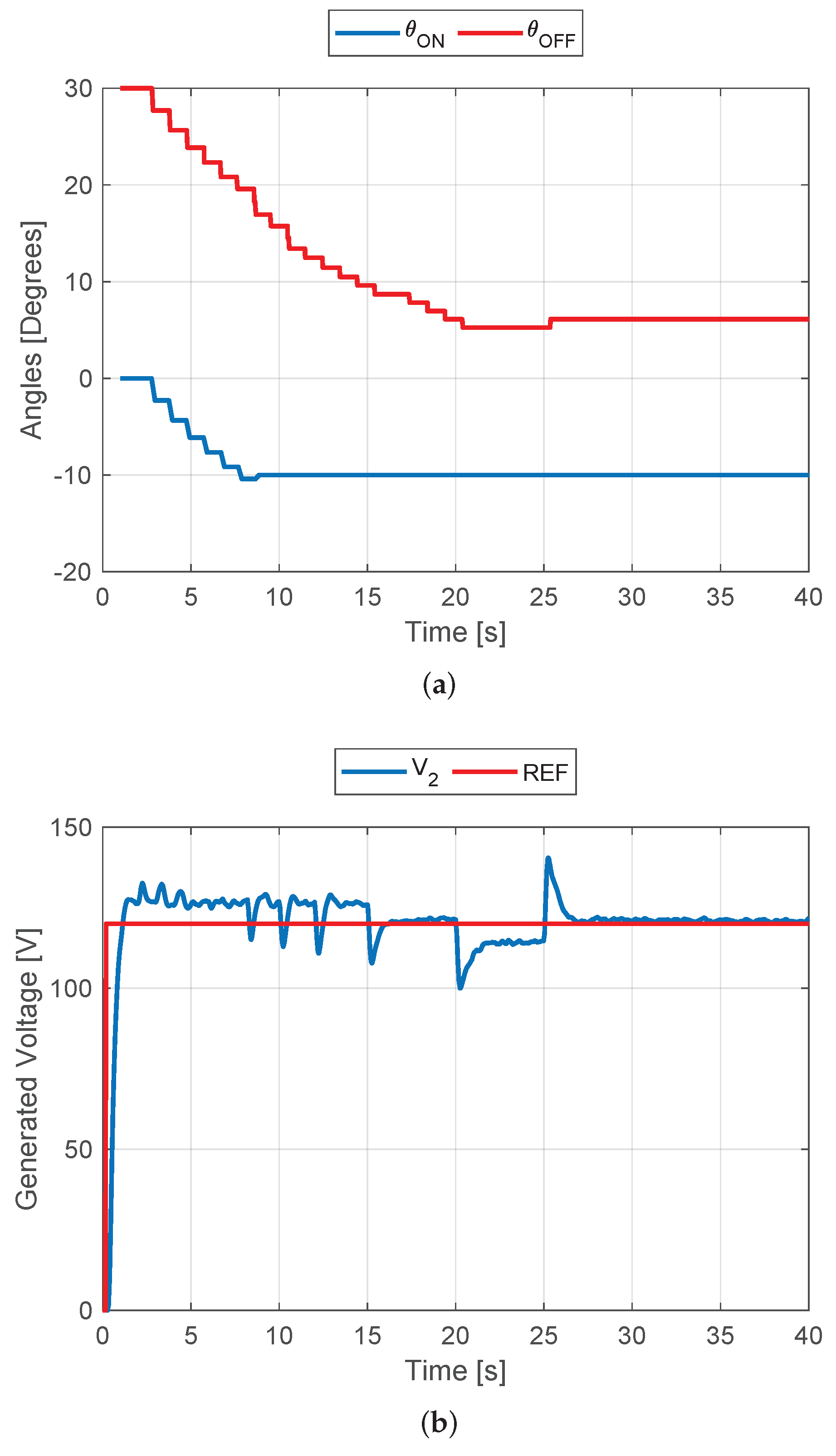
In
Figure 13a it is possible to see that the switching angles remain with the conventional window
and
for an instant of time. This one instant, as indicated by the algorithm, is the time required for the voltage to output to go into steady state by the actuation of the PID controller. Then, the driving window is delayed by
in
until it reaches its limit at
, a satisfactory value for the GRC, as presented previously. Then, the angle
starts to decrease by a perturb-and-observe algorithm, so that at each degree that
is decreased, the efficiency value is compared to the previous value, until the efficiency can no longer increase. In
Figure 13a, the angles are stabilized at
and
. This provides a driving window of
, minimizing the excitation power of the GRC and, consequently, increasing the generator’s efficiency.
Figure 13b shows the performance of the voltage PID controller acting in parallel with the MEPT tracking algorithm. The controller performance was satisfactory even with the disturbances in the switching angles of the converter. In this test, the reference used was 100 V.
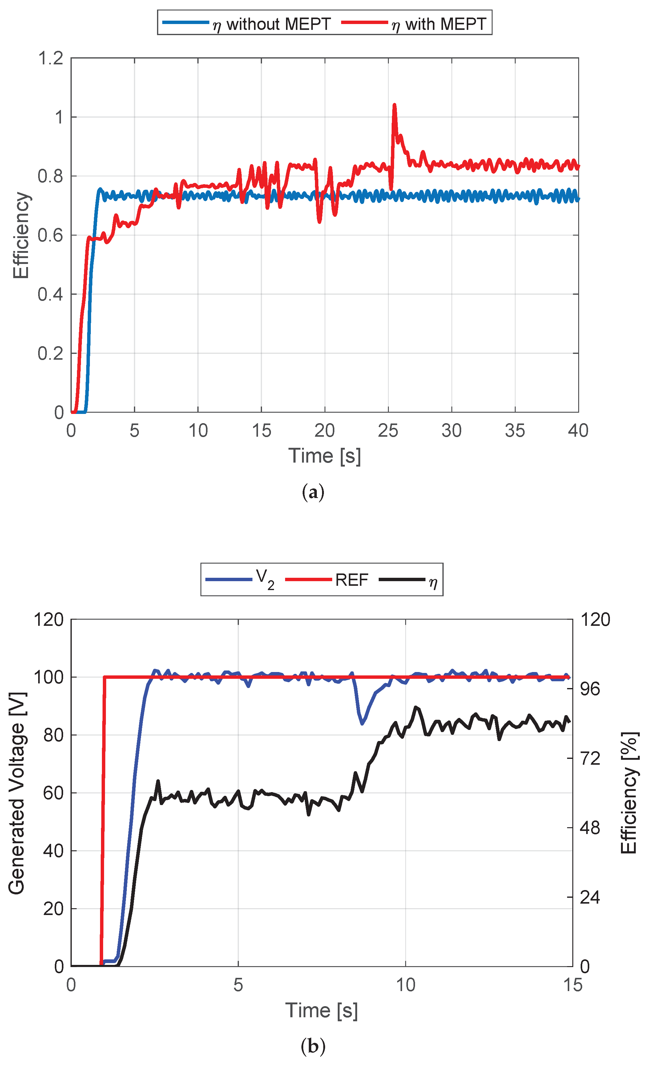
Figure 14 presents the results for the 100 V reference, illustrating the evolution of the GRC performance according to the performance of the MEPT algorithm and also the experimental result with the obtained angles.
In
Figure 14a, the GRC efficiency is raised from
to
. This is a result obtained by the computational model. In order to experimentally verify the performance of the MEPT algorithm, the angles provided by the algorithm, illustrated in
Figure 13a, were inserted into the experimental platform and the result is shown in
Figure 14b. It can be seen in
Figure 14b that, in addition to the controller having guaranteed the voltage regulation at the pre-established value by the reference (100 V), the efficiency was raised to approximately
, as indicated in
Figure 14b.
Figure 15 and
Figure 16 show the results for the same procedure as above, but with a reference voltage of 120 V for the controller.
In
Figure 15a, the switching angles have stabilized at
and
. In
Figure 15b, the PID controller kept the generator output at
, despite transient instability.
Figure 16a illustrates the evolution of GRC performance with the MEPT algorithm, where the efficiency increased from
to
. In the same way as in the previous procedure, the values obtained for the switching angles, that is,
and
, were used in the experimental platform, and the test result for
reference is shown in
Figure 16b.
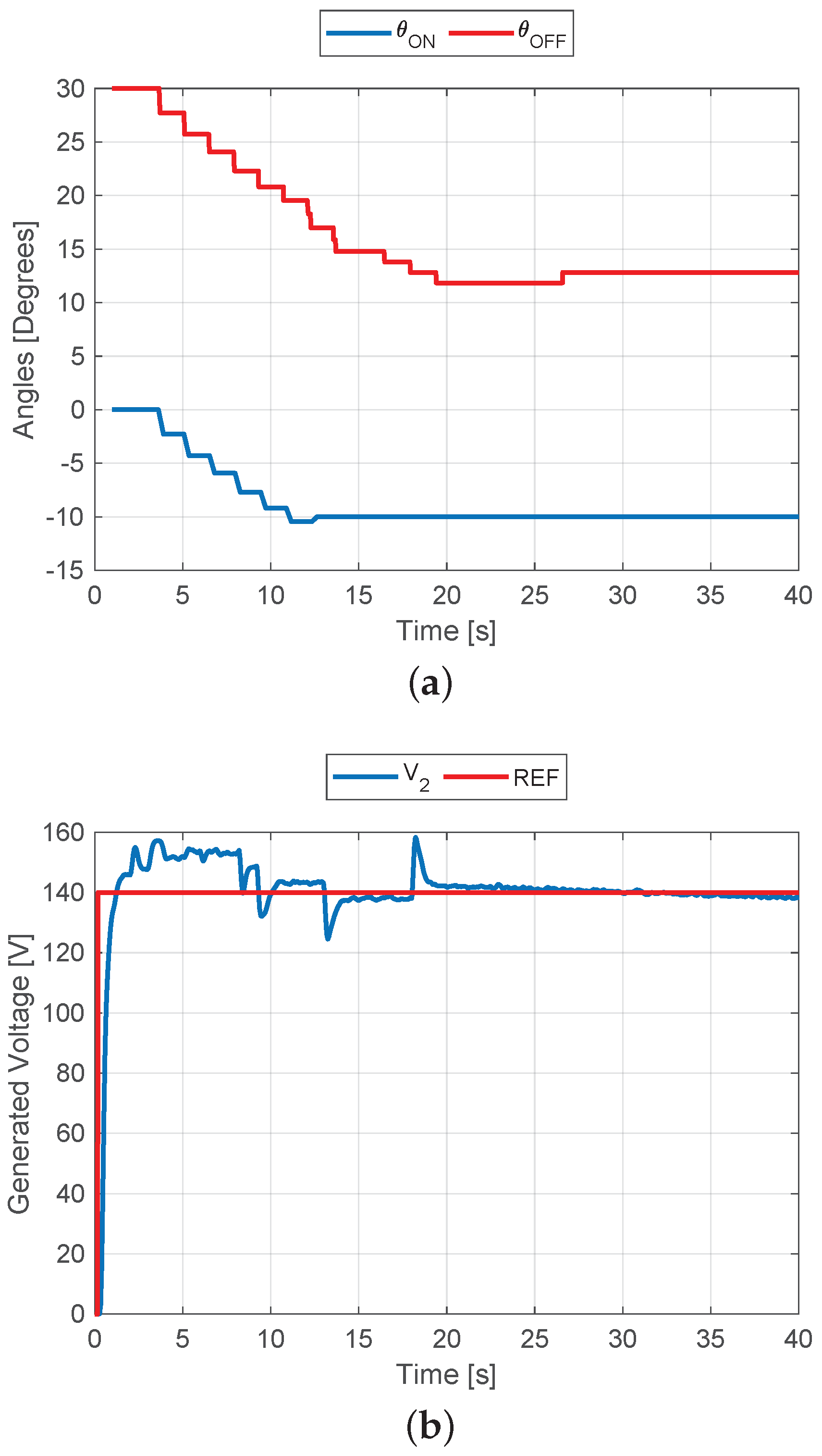
As the last experimental procedure to validate the MEPT algorithm in parallel with the voltage PID controller, the reference was raised to
. The results for this test are shown in
Figure 17 and
Figure 18.
The evolution of the switching angles illustrated in
Figure 17a, due to the action of the MEPT algorithm, results in the values
and
. The performance of the voltage PID controller, shown in
Figure 17b, indicates that the controller has a satisfactory action for operation in parallel with the MEPT algorithm, considering its adjustment made by the optimization process. The generator output was maintained at values close to the 140 V reference.
In
Figure 18a, the GRC efficiency evolved from
to
as a result of simulation. Finally, the angles
and
obtained by the algorithm of tracking were applied to the experimental platform, and the result obtained is shown in
Figure 18b, where there is also an increase in efficiency of the generator.
5. Discussion
The development of this work is supported by previous research in which the reluctance machine was designed and built, however, for operation as a motor with current control in an attempt to minimize the oscillations of the conjugate produced. In this way, the beginning of the development of this work took place with the construction of the experimental platform for the activation and control of the machine as a generator.
Then came the first difficulties, because the generator voltage control requires implementation of more elements, which makes the system more demanding in terms of the adjustments and, consequently, makes it more difficult to present results consistent with the computational model. On the other hand, obtaining the inductance surface using regression for metric contributed positively to this difficulty, as it provided results simulations closer to the experimental platform than the models already known, in addition to requiring less computational effort.
The studies conducted in this article take into account the use of the switched reluctance generator in wind power generation systems. The SRG has some advantages that make it interesting for this type of application. Several studies on the control of the SRG output voltage have already been conducted by the scientific community, as presented by [
30], even employing modern control techniques, as presented in [
31,
32,
33]. In this work, in addition to controlling the output voltage of the SRG, there is an interest in enhancing the efficiency of the machine. Works such as [
34] also have a quest to improve machine performance. Some studies, such as [
12,
13], use tracking techniques to enhance the power generated by the SRG. However, in this work, the output voltage driver, despite being a traditional controller (PID), was optimized and associated with a tracking technique, however, not the conventional MPPT technique, but a technique that seeks to enhance the efficiency of the generator. In this study, the SRG was subjected to output voltage control for different setpoint values, and the machine’s performance was evaluated considering metrics such as its efficiency and torque ripple.
Thus, it is expected that the SRG can contribute positively to the generation of energy in isolated or in distributed generation systems when employed with the techniques shown in this article, making better use of primary sources due to the elevation achieved for its efficiency. In addition, it is expected that the generation system that employs the SRG and the techniques shown in this study can contribute to the useful life of the structures, implying less maintenance, with a view to reducing the torque ripple of the generator.
Future studies can be applied in order to improve the performance of the PID controller when associated with the MEPT algorithm proposed in this article. As a suggestion, PID controller optimization techniques can be applied in conjunction with the MEPT algorithm to improve the performance of the output voltage control, aiming to minimize variations when MEPT contribution occurs.
Tracking techniques, whether of power or efficiency, can be easily used in practice, as they do not require major hardware modifications for their implementation. An example can be seen in [
35], where experimental results of the application of an MPPT algorithm in a wind turbine are presented.
6. Conclusions
In this article, the SRG was proposed as an alternative to conventional machines for wind generation systems. As the SRG is a DC machine, this study aimed at the application of a PID controller for the generator’s output voltage, making it possible to apply the output voltage in AC–DC converters or load controllers. The PID controller implemented here was optimized so that the proportional, integral, and derivative gains could present better dynamic performance to the controller. A substantial advantage of the optimized controller, especially in wind power applications, is the fact that greater robustness provided by the optimization process enables the SRG to operate over a wide speed range.
An evaluation was carried out in order to verify if the control of the SRG output voltage provides better results using the excitation voltage or the turn-on angle as the manipulated variable. In this case, it was found that although the control by the turn-on angle provides some better results than the control by the excitation, the control by presents a disadvantage that eliminates it as an option. This disadvantage is related to the fact that for this type of control, the voltage on the generator’s DC bus can be raised above its nominal voltage.
As the main objective of this work is to enhance the efficiency of the SRG, a tracking algorithm was developed and implemented in parallel with the PID controller. This algorithm seeks to track the maximum efficiency point of the SRG regardless of the assigned setpoint or the rotor speed of the generator. Simulation results were presented in order to show that the association of the PID controller with the MEPT algorithm positively contributes to the enhancement of SRG efficiency, making the machine even more attractive for wind generation systems.
The simulation results presented in this article indicate an SRG, whose construction characteristics provide efficiency less than , in some cases. This is because the SRG under study was simulated with the real physical characteristics of a machine manufactured nonindustrially. Thus, as the inductance profile used in the computational model takes into account the experimental data of current and angular position of this machine, the results presented refer to the machine used as the model of the study. However, the MEPT algorithm was able to increase the efficiency of the generator, proving its effectiveness for different output voltage values and in the face of disturbances in the load fed by the generator.


 ,
, 


