Abstract
Steel tire cord and steel saw wire represent typical precision pearlitic steel wire rods of wire products; it is a very important solar energy material with a diameter about 50 μm. This paper mainly discusses the research progress of the wire rod drawing process, and its main contents are as follows: First section—the control of the wire rod surface quality is summarized, including the thickness of the surface decarburization layer, the phase composition and thickness of the surface iron oxide scale, and the removal of surface iron oxide scale. Then, the research progress of the wire rod water bath treatment process during sorbitization is summarized. In addition, the development of brass plating technology for steel wire is summarized, including copper plating technology, coating phase composition, etc. Furthermore, the development of steel wire drawing methods is summarized. Finally, the development of the dies used in steel wire drawings is summarized.
1. Introduction
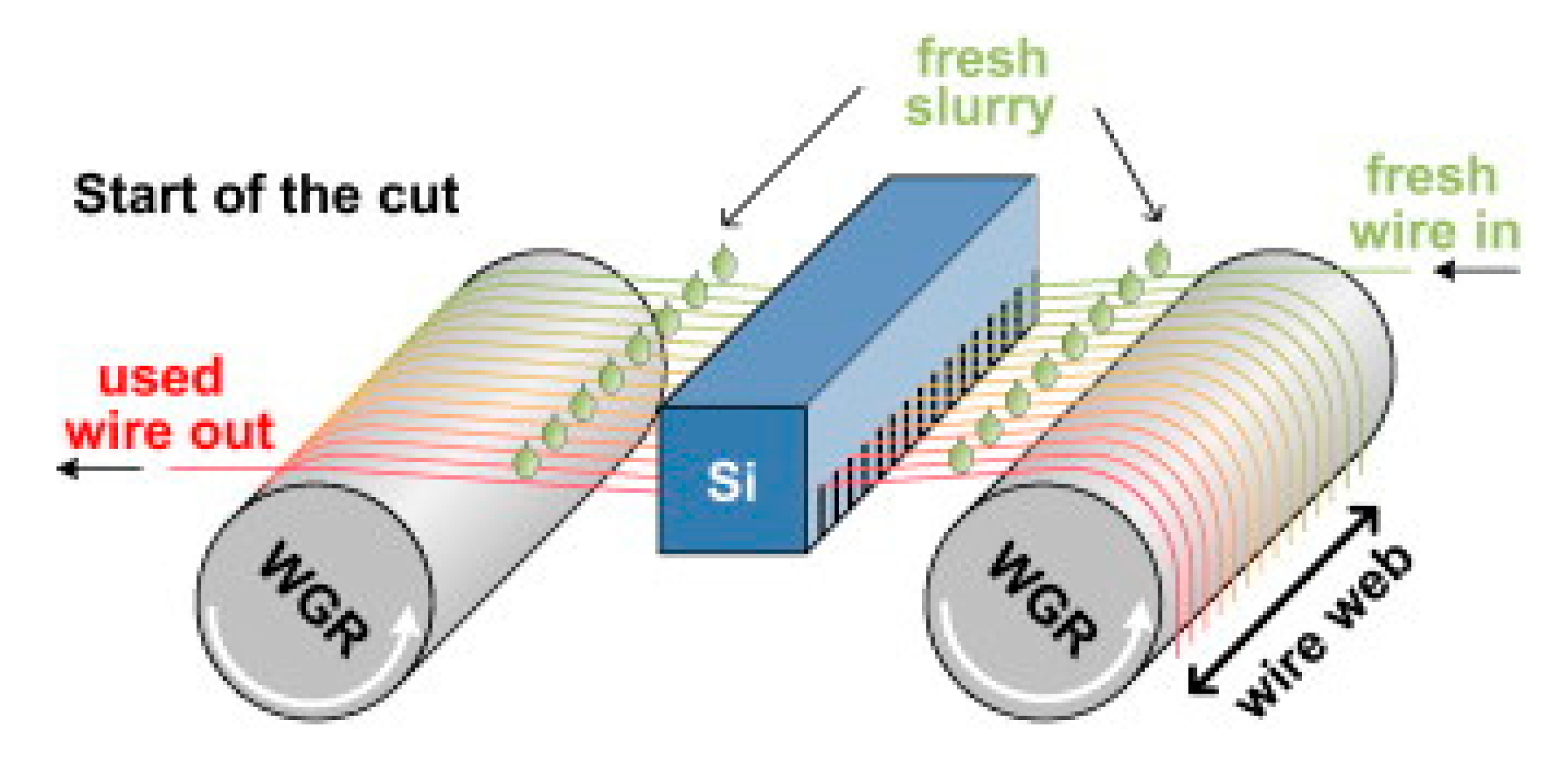
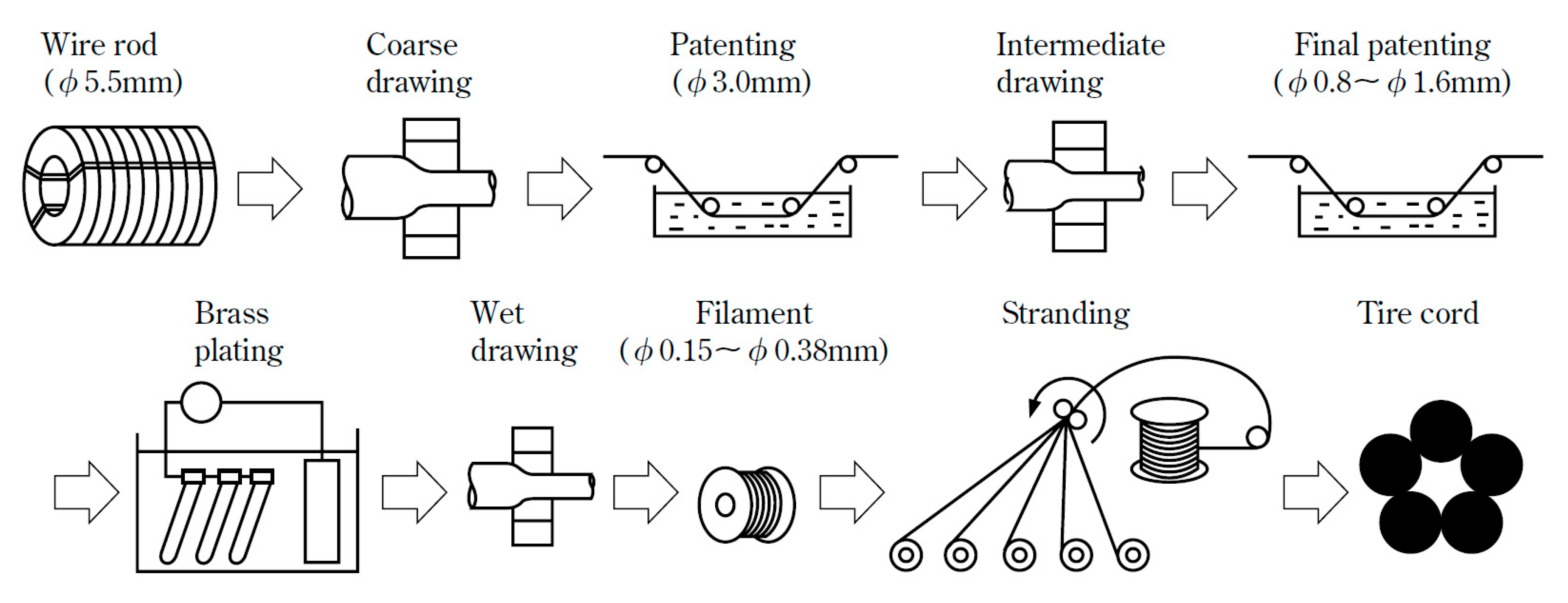
Steel cord with a diameter about 80 μm is mainly used to make tire frame material, and steel saw wire with diameter about 50 μm is mainly used to cut the silicon wafers used for solar cells, as shown in Figure 1 [1]. With the rapid development of the automotive industry and global photovoltaic industry, the demand for solar energy materials and the necessary materials to produce them, steel tire cord and steel saw wire are also increasing rapidly. The drawing process is the same as that of cord steel wire, but the steel saw wire needs to be drawn more times due to its diameter is smaller, as shown in Figure 2 [2].
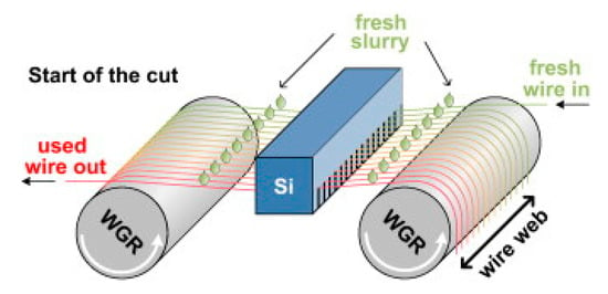
Figure 1.
Schematic diagram of the working principle of a multi-wire saw for a saw steel wire. Reprinted with permission from ref. [1].
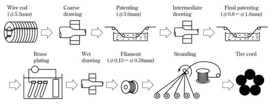
Figure 2.
Drawing process diagram of a steel cord and steel wire saw. Reprinted with permission from ref. [2].
The typical chemical composition of steel cord and saw wire rod used is shown in Table 1, and the properties of the wire/wire rod are shown in Table 2. The most common problem in the production and use of tire steel cord and saw wire is wire breakage. Once the tire steel cord breaks, it is very easy to cause tire explosion, resulting in serious traffic accidents. Once the steel saw wire breaks, the whole silicon rod will be scrapped, which will cause serious economic losses [1]. Therefore, every effort should be made to reduce the wire breaking rate of steel cord and saw wire. For ultra-fine steel wires such as steel cord and saw wire, any defect in the production process may lead to wire breakage, such as large-scale hard inclusions in the steel wire, too-thick iron oxide scale on the steel wire surface, uneven internal structure of the steel wire, insufficient compact coating structure on the steel wire surface, damage of grinding tools for drawing steel wire, etc. [2].

Table 1.
The typical chemical composition of a steel cord and saw wire rod.

Table 2.
The properties of a saw wire rod.
To produce high-quality steel saw wire, it is not only necessary to making high-quality steel but, also, to have a drawing process suitable for the rod. It takes many steps to process the wire to be qualified. Each step has a crucial influence on the quality of the finished steel wire. Therefore, strict control is needed in the whole process.
This paper discusses the control of oxide skin on the surface of steel wire, the sorbitization body treatment method, brass plating process, drawing method for steel wire, dies used in wire drawing, etc. In addition, based on the summary of the past research, five problems that need to be studied in the future are pointed out.
2. Surface Quality Control Technology of Wire Rod
2.1. Control of the Decarburization Layer on the Wire Rod Surface
The surface quality of the wire rod is mainly influenced by the decarburization layer and oxide scale. The occurrence of a decarburized layer structure deteriorates the mechanical properties of the wire rod, which is shown as a rapid decrease in its fatigue strength. Cracks form quickly, and fatigue fracture occurs in the subsequent drawing process of steel cord or cutting wire, which seriously affects its service performance [1,2,3,4]. Therefore, the control of the decarburization layer on the surface of hot-rolled wire rod in the form of steel cord and steel saw wire is particularly important.
At present, the market standard for decarburization layer of wire rod is the thickness ≤1.2% D (“D” is the diameter of the wire rod.) [5]. In addition, according to Li et al.’s experimental results [6], the hardness of SWRH77A steel wire rod decreased gradually from 296 HV to 276 HV when the depth of total decarburization layer increased from 0.02 mm to 0.28 mm. Furthermore, the decarburization of the wire rod surface will lead to excessive surface residual stress, resulting in microcracks on the wire surface.
At present, the research on the surface decarburization control of wire rod is mainly focused on spring steel and cold heading steel, while research on cord steel and saw wire steel is rare. Regarding the spring steel and other wire rods, the existing study is a small-scale thermal simulation experiment, which is quite different from the actual production [7,8,9]. Bearing this in mind, Zhao et al. [10] explored the process optimization of the cord steel decarburization layer control.
The main factors affecting the decarburization of a finished wire rod (with Ф 5.5-mm diameter) are the original billet decarburization constitution, reheating decarburization inheritance of the billet, and secondary decarburization produced by controlled cooling [11,12]. Therefore, Zhao et al. [10] optimized these three issues and formulated the following conclusions:
- (1)
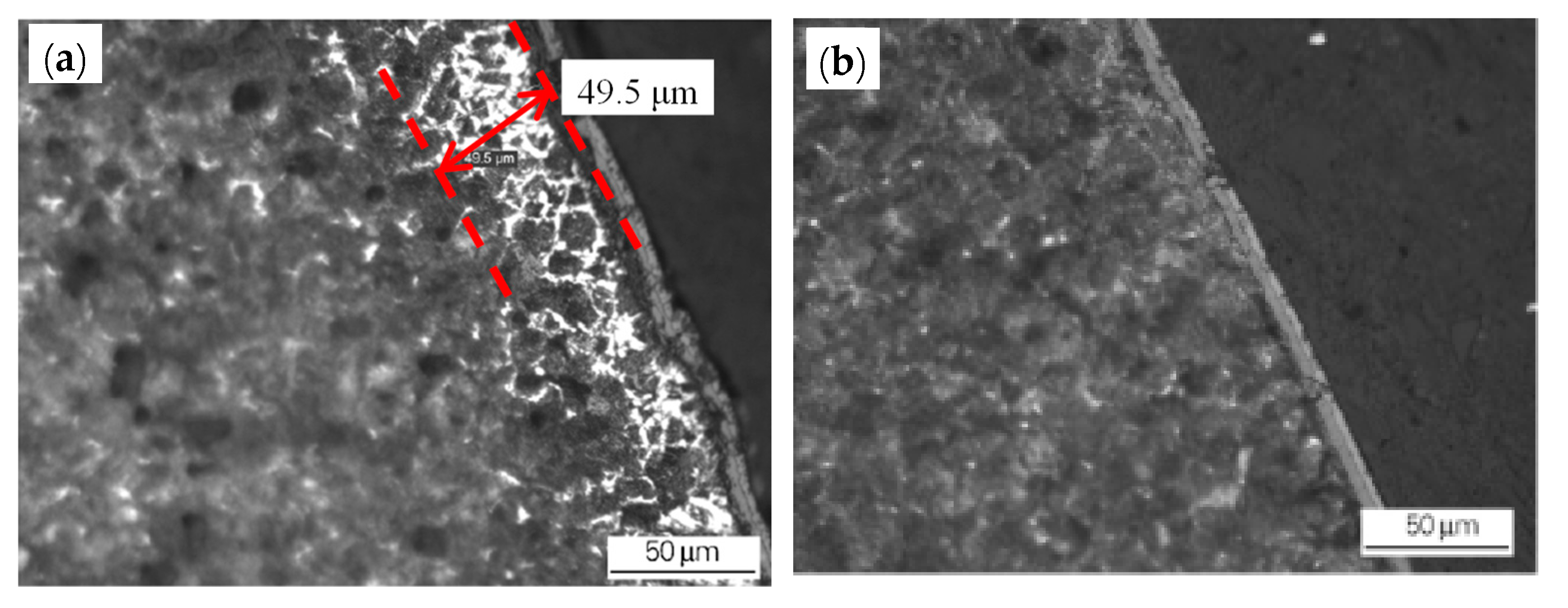
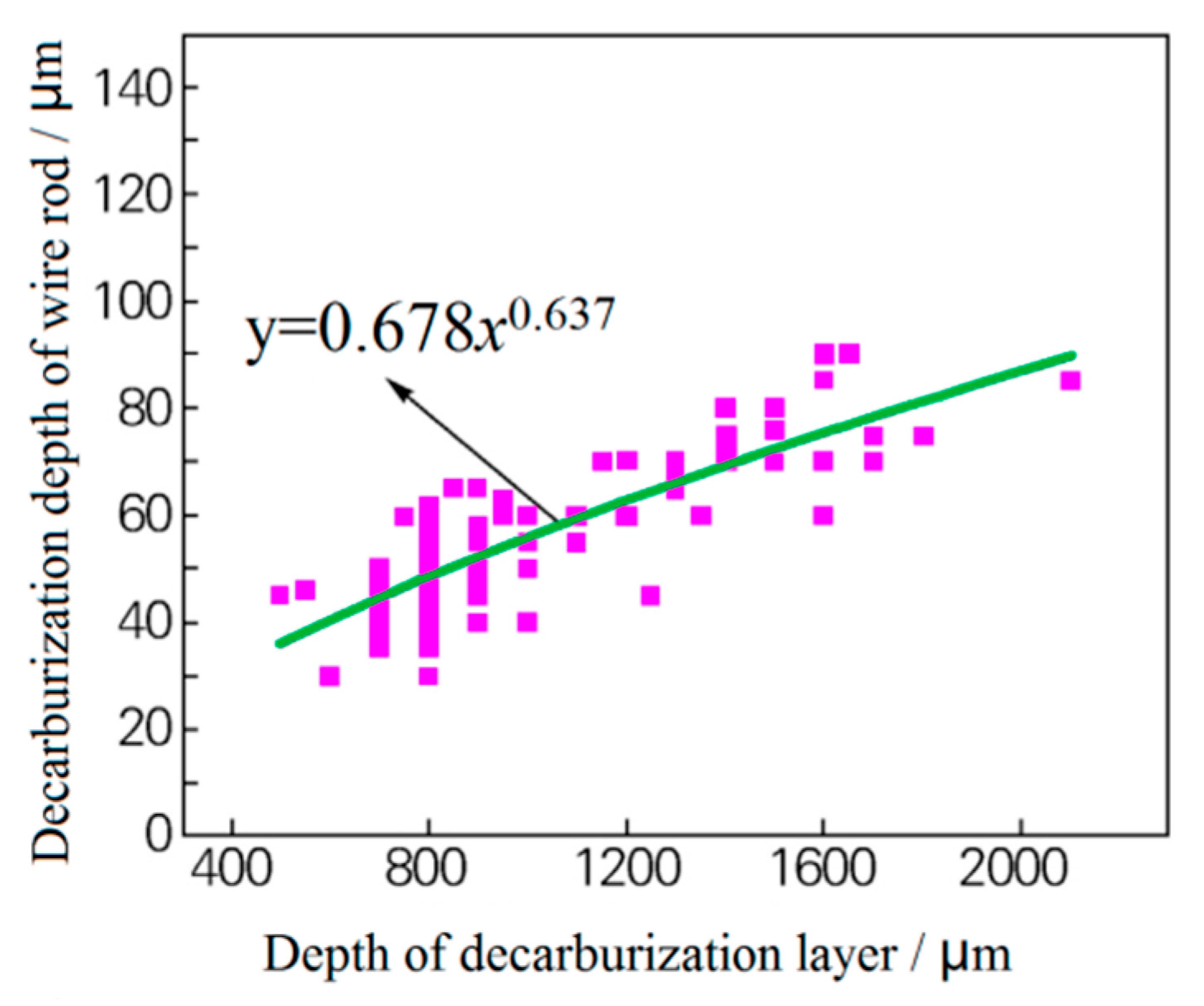
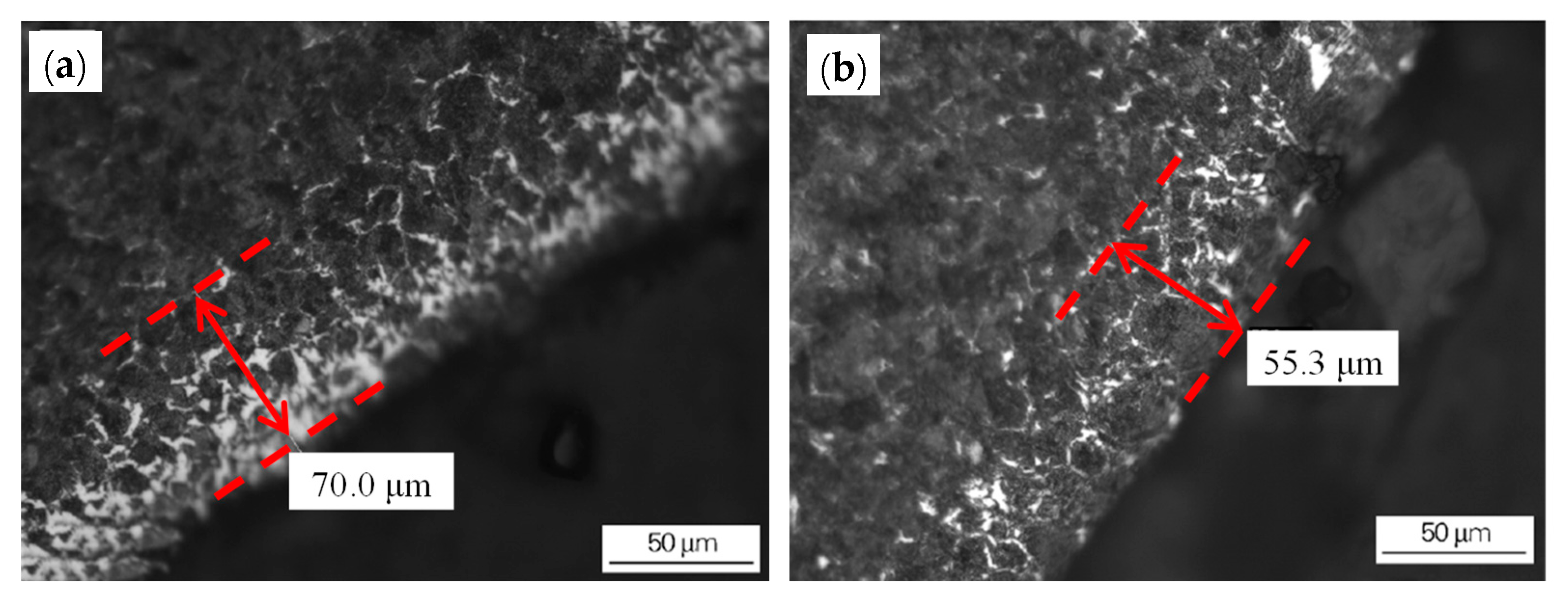
- The original decarburized layer can be effectively removed by grinding of the blank surface, which will reduce the thickness of the surface decarburized layer of the hot-rolled wire rod (Figure 3). There is a relation between the depth of the original decarburized layer on the billet surface and the thickness of the decarburized layer on the finished wire rod’s surface, as shown in Figure 4. The grinding of the original decarburized layer on the surface of the billet is critical for the thickness reduction of the decarburized layer on the surface of the finished wire rod.
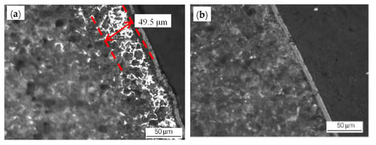 Figure 3. Effect of the grinding of the blank surface on the decarburization layer of the rolled wire rod: (a) blank (unpolished) surface and (b) the decarburized layer on the polished surface of the rolled wire rod. Reprinted with permission from ref. [10].
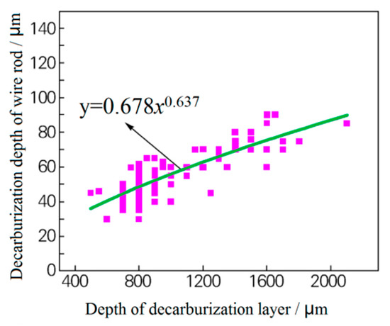 Figure 4. Relationship between the thickness of the original decarburized layer of the billet and the thickness of the wire rod. Reprinted with permission from ref. [10].
 - (2)
- In hot-rolling, the depth of surface decarburization layer of hot-rolled wire rod for a P72LXA steel cord can be reduced by decreasing the actual high-temperature area (900–1050 °C) of the billet heating section and extending the low-temperature area (600–800 °C) of the preheating section.
- (3)
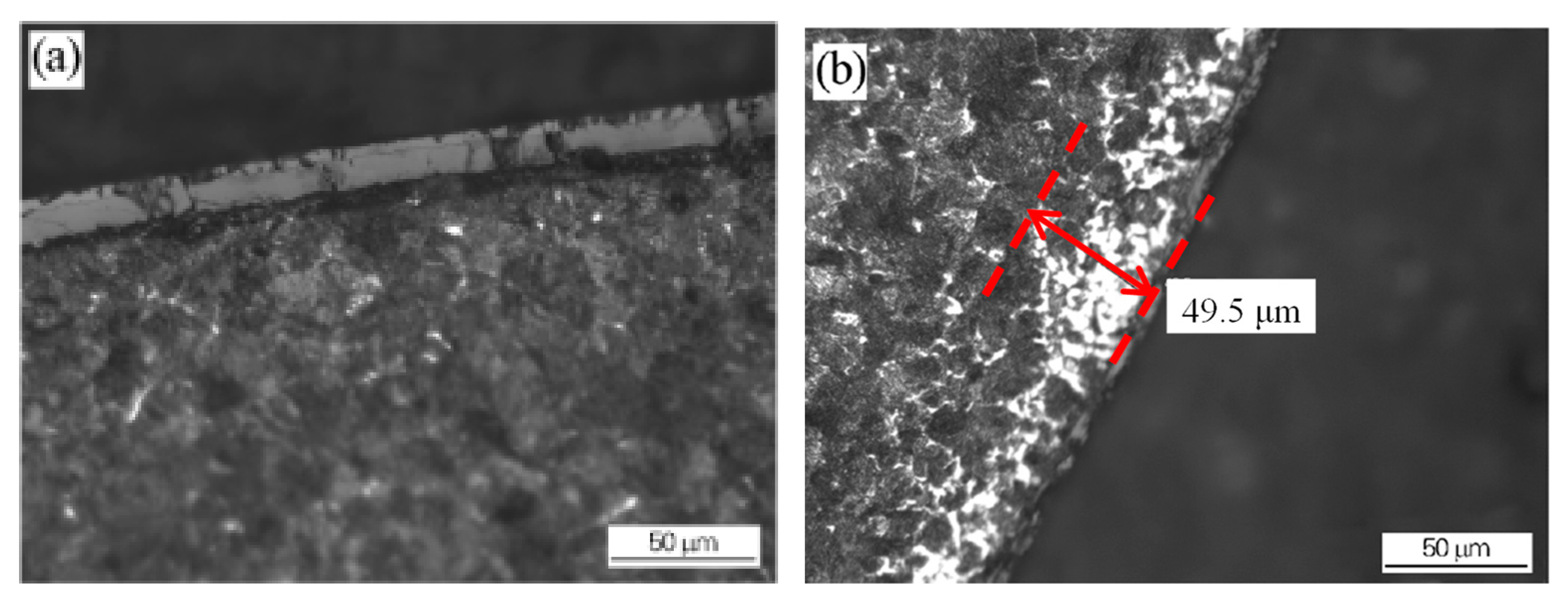
- The surface decarburized layer can be transformed into an oxide layer by the proper increasing of the spinning temperature, as shown in Figure 5 and Figure 6. As shown in Figure 6a, when the wire spinning temperature of the wire rod is 1000 °C, there is almost no decarburization layer, but the surface iron oxide scale is thick, which is 13~20 μm.
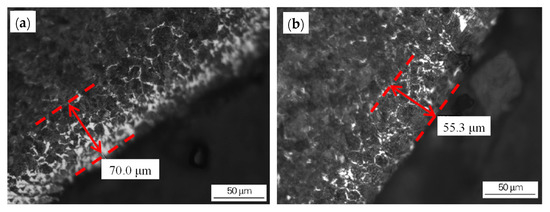 Figure 5. Decarburization of the wire rod before and after the optimization of the heating process: (a) wire rod rolled from billet 1 using the conventional process and (b) wire rod rolled from billet 2 using the optimized process. Reprinted with permission from ref. [10].
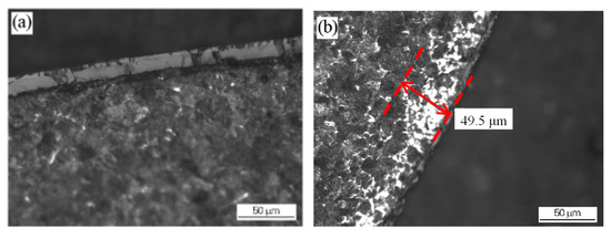 Figure 6. Decarburization of wire rod rolled at different spinning temperatures: (a) 1000 °C NS (b) 895 °C. Reprinted with permission from ref. [10].
Nevertheless, it should be noted for “(2)”, the method that is used by the authors was right, but would it ensure the same properties of steel wire rod? If the holding time in the high temperature section (900–1050 °C) is too short, it may lead to insufficient austenization of the steel wire structure, resulting in the failure of the uniformity of the steel wire structure to meet the requirements.
At present, the control technology of the surface decarburization layer of cord steel is relatively well-developed, and the thickness of the decarburization layer is close to zero.
2.2. Control of Oxide Scale on the Wire Rod Surface
The oxide scale on the wire rod surface can prevent the steel wire from rusting, which facilitates the storage and transport of the wire rod for a long time. It is necessary that the oxide scale has good adhesion performance. Additionally, the adhesion should not be too strong, since it can hinder the phosphorus removal before wire rod drawing. Should incomplete dephosphorization occur, the remaining oxide scale on the steel wire surface may damage the wire drawing die in the process of steel wire drawing and even become a crack source and cause a fracture in the steel wire. Therefore, an optimal balance between the scale adhesion and detachment is particularly important [13].
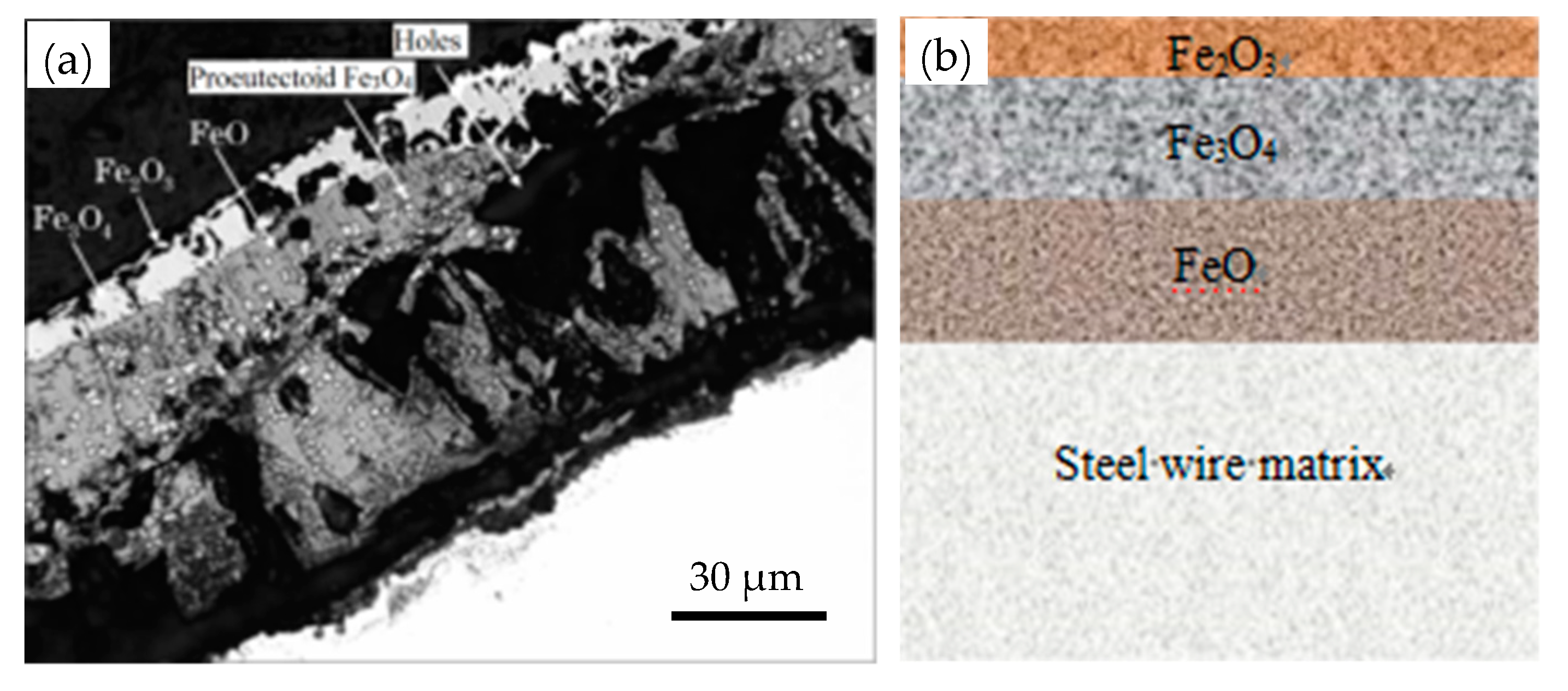
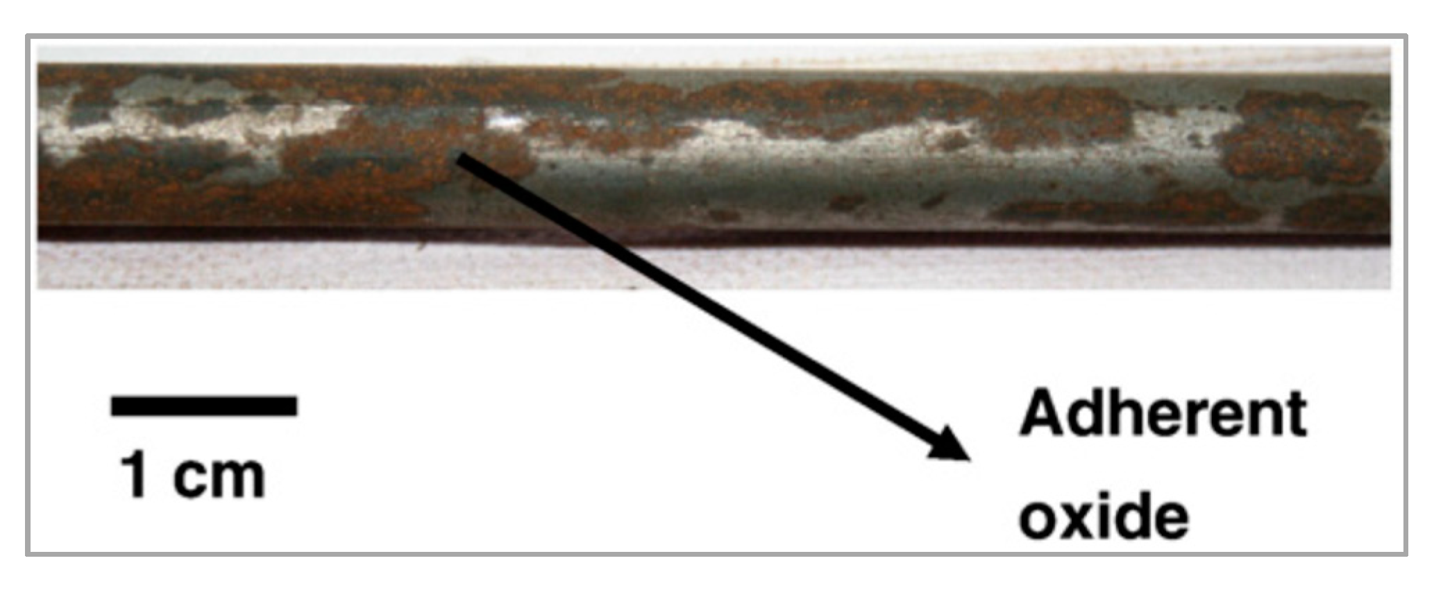
The scale detachment is mainly affected by three factors: thickness, microstructure, and the oxide’s phase composition. Figure 7 shows a typical scale structure [14]. The FeO is loose and can easily detach, while Fe3O4 is dense and exhibits good adhesion to the matrix, but the mechanical phosphorus removal in the subsequent process is difficult, as shown in Figure 8 [15]. Therefore, control of sheet metal thickness and phase structure is one of the key approaches for mechanical descaling improvement.
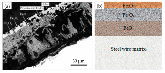
Figure 7.
Structure of the oxide scale on the surface of a wire rod for a steel cord: (a) image under a scanning electron microscope and (b) a schematic diagram. Reprinted with permission from ref. [14].
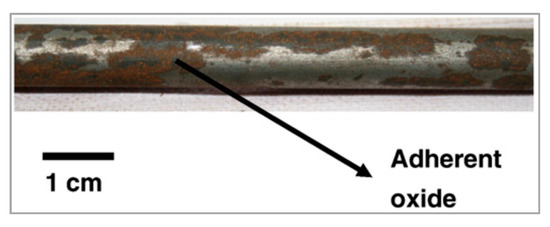
Figure 8.
Photograph of a mechanically descaled wire rod showing adherent oxides. Reprinted with permission from ref. [15].
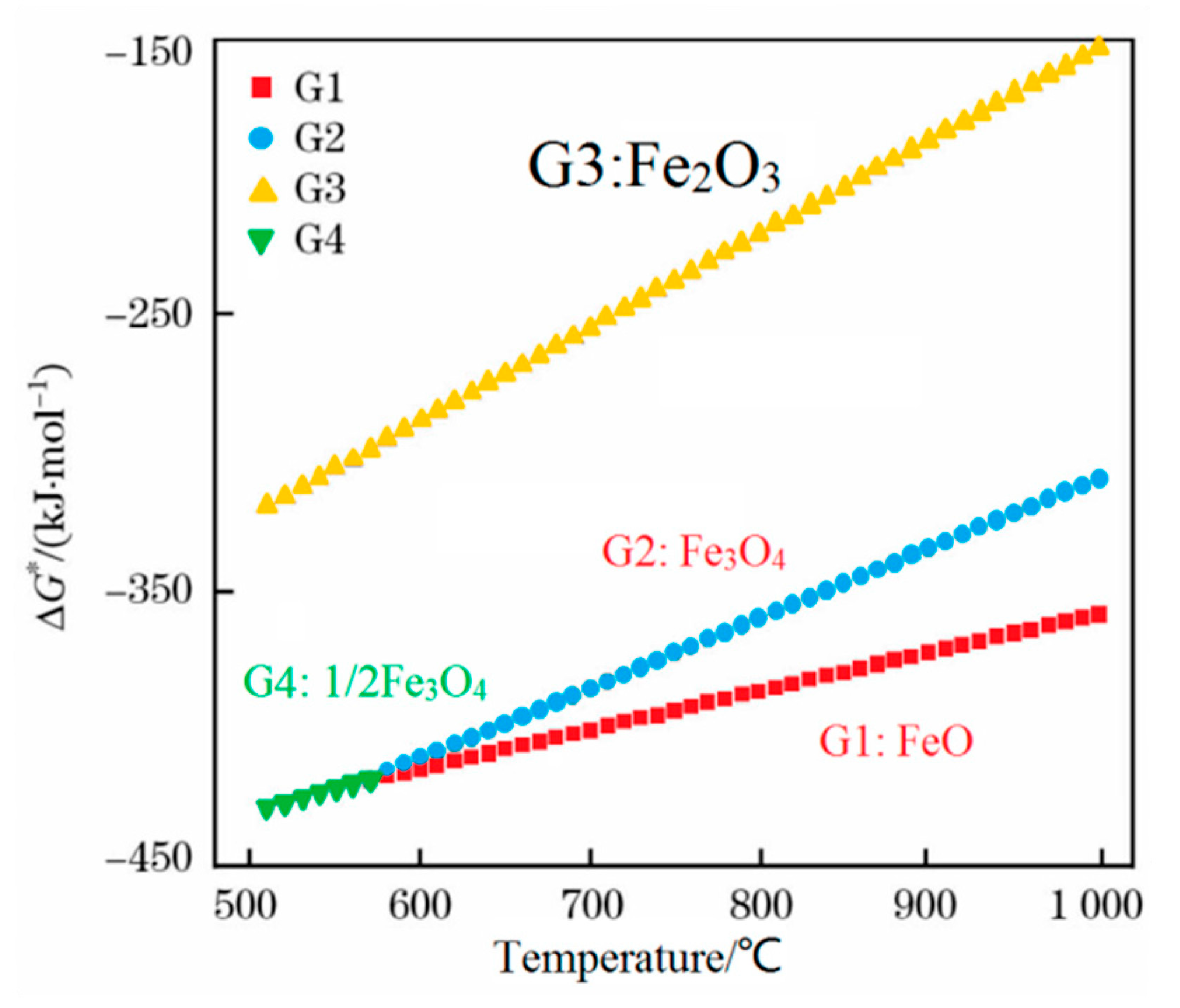
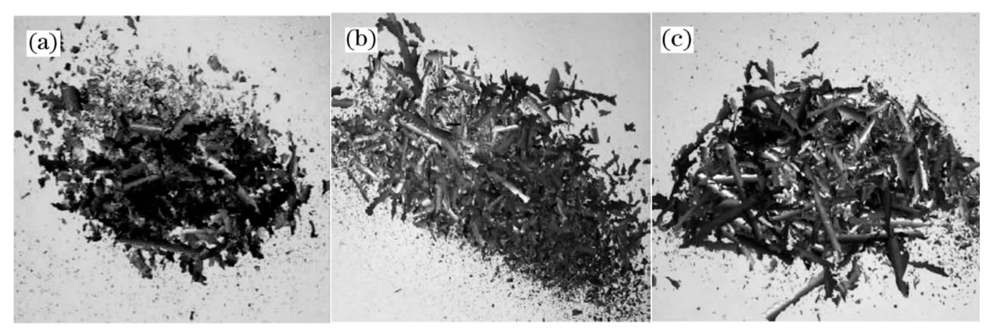
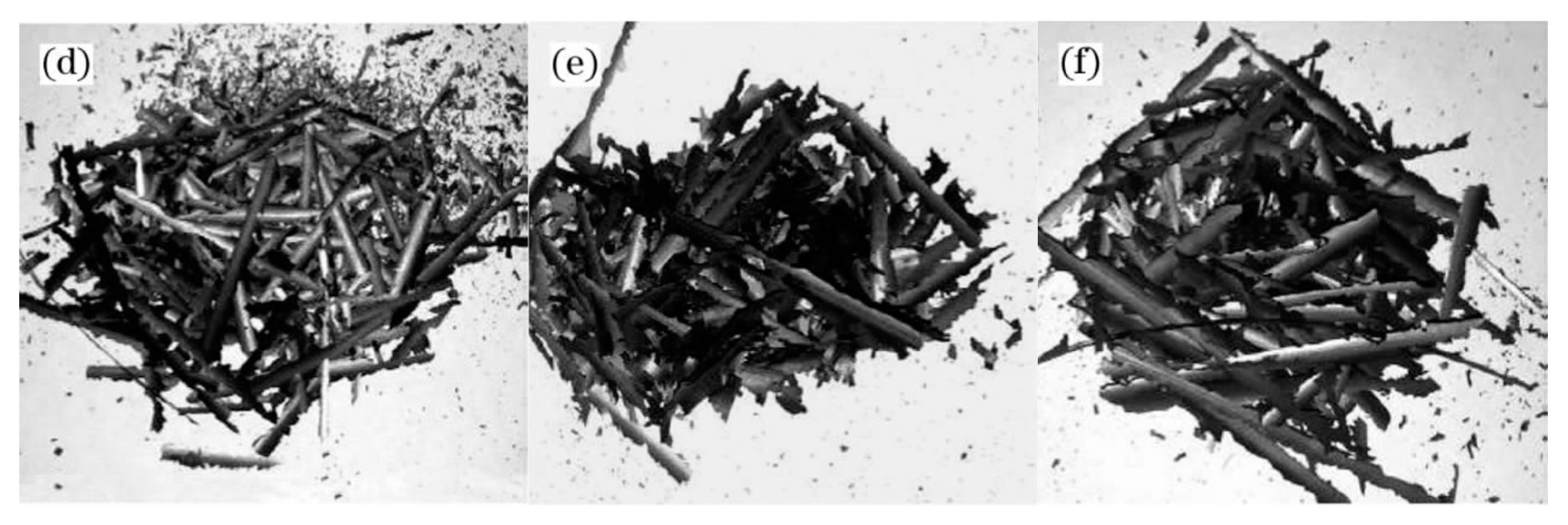
A thermodynamic diagram of Fe-O oxides formation is shown in Figure 9 [16], and the equations that correspond to each curve are shown in Equations (1)–(4) [16]. Higher temperatures are beneficial for the growth of FeO. Guo et al. [16] investigated this topic and showed that the iron oxide scale with a high FeO amount in the wire rod forms quickly at higher spinning temperatures. However, if the spinning temperature is too high, the thickness of the iron oxide scale, which significantly influences the total weight of the wire rod, will affect the metal yield. Therefore, the spinning temperature is 940–900 °C. The experimental results are shown in Figure 10. It is obviously that the trend of large-scale peeling of the wire rod scale is becoming more and more obvious with the increase of the spinning temperature, and the descaling performance of the wire rod scale is gradually improved, which is caused by the increase of the FeO content in the wire rod scale. After the wire spinning temperature exceeds 900 °C, its descaling performance can achieve the user’s requirements, as shown in Figure 10d–f. A too-high spinning temperature leads to a too-thick iron oxide scale of the wire rod, and the percentage of the iron oxide scale in the total weight of wire rod is too high, which affects the metal yield for users. Therefore, in the actual production process, it is better to control the spinning temperature of the wire rod at 900–940 °C.
G1: 2Fe(s) + O2 = 2FeO; ΔG* = −539080 + 140.56 T J·mol−1
G2: 6FeO(s) + O2 = 2Fe3O4(s); ΔG* = −636130 + 255.67 T J·mol−1
G3: 4Fe3O4(s) + O2 = 6Fe2O3(s); ΔG* = −586770 + 340.20 T J·mol−1
G4: 3/2 Fe(s) + O2 = 1/2Fe3O4; ΔG* = −586320 + 169.24 T J·mol−1
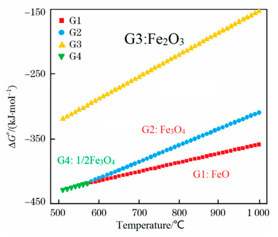
Figure 9.
Thermodynamic diagram of the Fe-O oxides formation. Reprinted with permission from ref. [16].
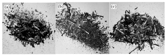
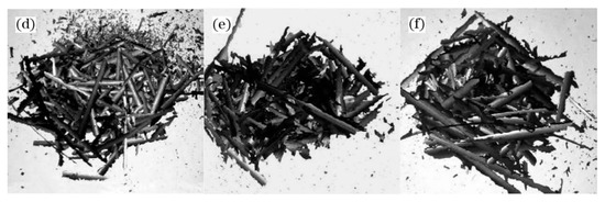
Figure 10.
Morphology of the iron oxide scale on the surface of a steel cord wire rod under different spinning temperature treatments: (a) 870 °C, (b) 880 °C, (c) 890 °C, (d) 905 °C, (e) 910 °C, and (f) 925 °C. Reprinted with permission from ref. [16].
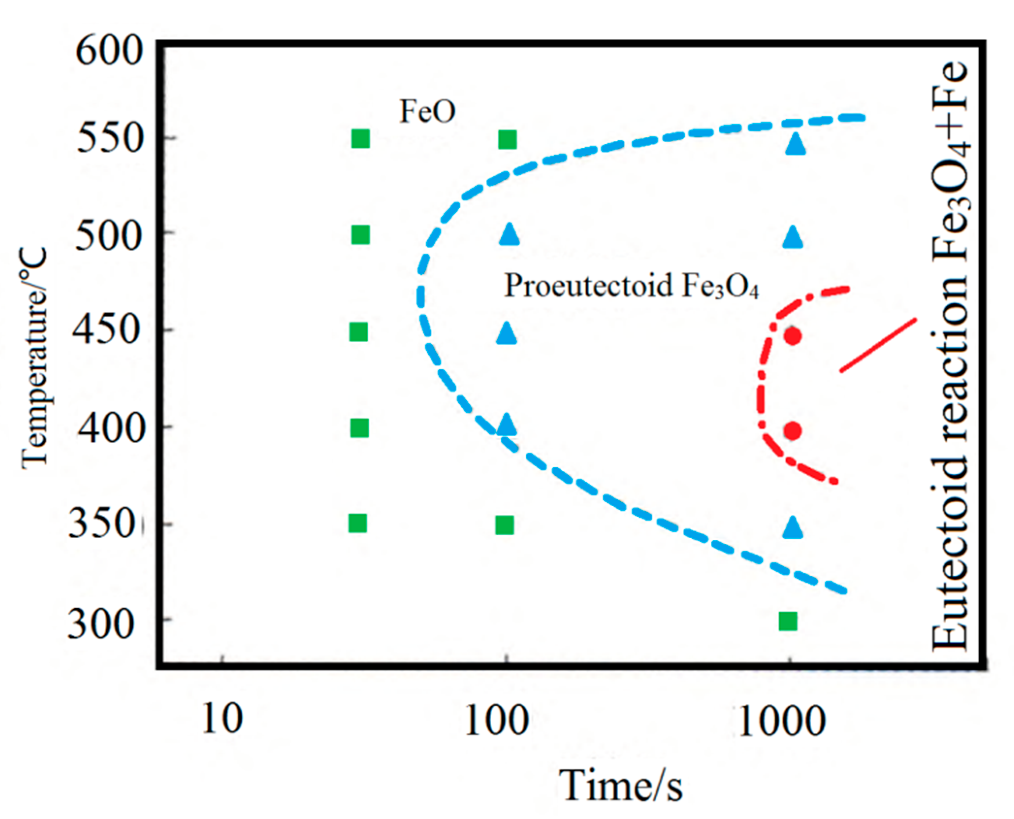
FeO will undergo an eutectoid reaction at 560 °C to produce Fe3O4 with a dense structure and good adhesion to the matrix, hindering the mechanical descaling [17]. Therefore, it is essential to control the FeO eutectoid transformation during steel wire cooling. L. P. Wang determined the FeO isothermal transformation curve on the surface of cord steel (0.82C-0.2Si-0.5Mn) in the production test, as shown in Figure 11 [18]. It can be seen that the temperature range of 400–500 °C is the “nose-tip” temperature range for the pro-eutectoid and eutectoid transformation of the FeO layer, with the fastest transformation rate and the shortest incubation period. Control of the cooling rate between 400 and 500 °C is crucial to prevent the Fe3O4 scale formation from the pro-eutectoid or eutectoid transformation of the FeO layer.
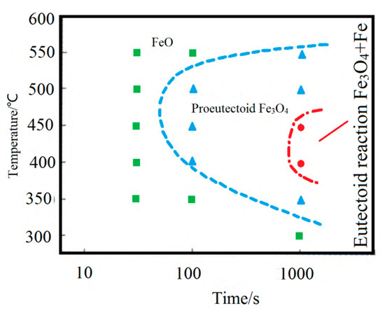
Figure 11.
FeO isothermal transformation curve. Reprinted with permission from ref. [18].
2.3. Removal of Oxide Scale from the Wire Rod Surface
The commonly used approaches for the removal of the iron oxide scale from the surface of the wire rod are bending roller mechanical descaling (descaling machine is shown in Figure 12) and pickling [19,20]. Qi et al. [21] surveyed the literature data and summarized, in Table 3, the disadvantages of all the descaling methods.
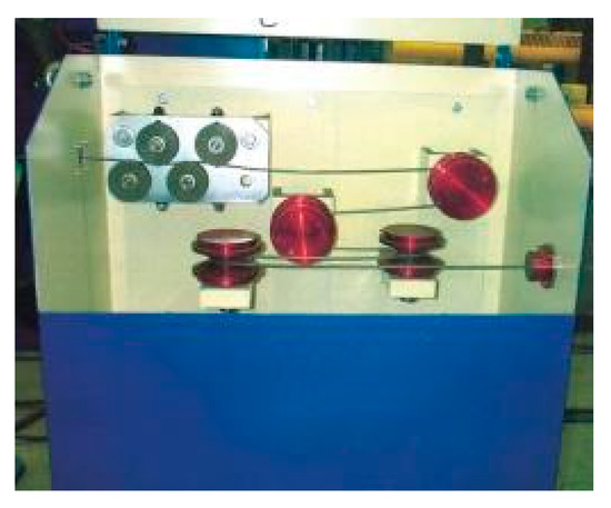
Figure 12.
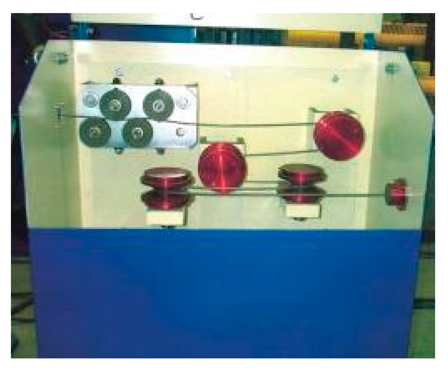
Eight-roller descaling machines.

Table 3.
Different scale removal processes of a wire rod. Reprinted with permission from ref. [21].
Recently, Qi et al. [21]. tried to combine various descaling methods. (1) single bending roller, (2) bending roller + wire brush, (3) bending roller + pickling, and (4) single pickling. The efficiency of the four descaling methods is arranged in the following order: bending roller + pickling > bending roller + wire brush > ingle pickling > single bending roller. The acid washing method is not advised, since it consumes high amounts of acid and pollutes the environment. The bending roller + wire brush method requires less investment and can remove more than 90% of the oxide scale from the wire rod surface. After the optimization of the process and equipment, it does not damage the wire rod matrix, and it can completely meet the production standards and replace the pickling process.
3. Water Bath Instead of Lead Bath Heat Treatment
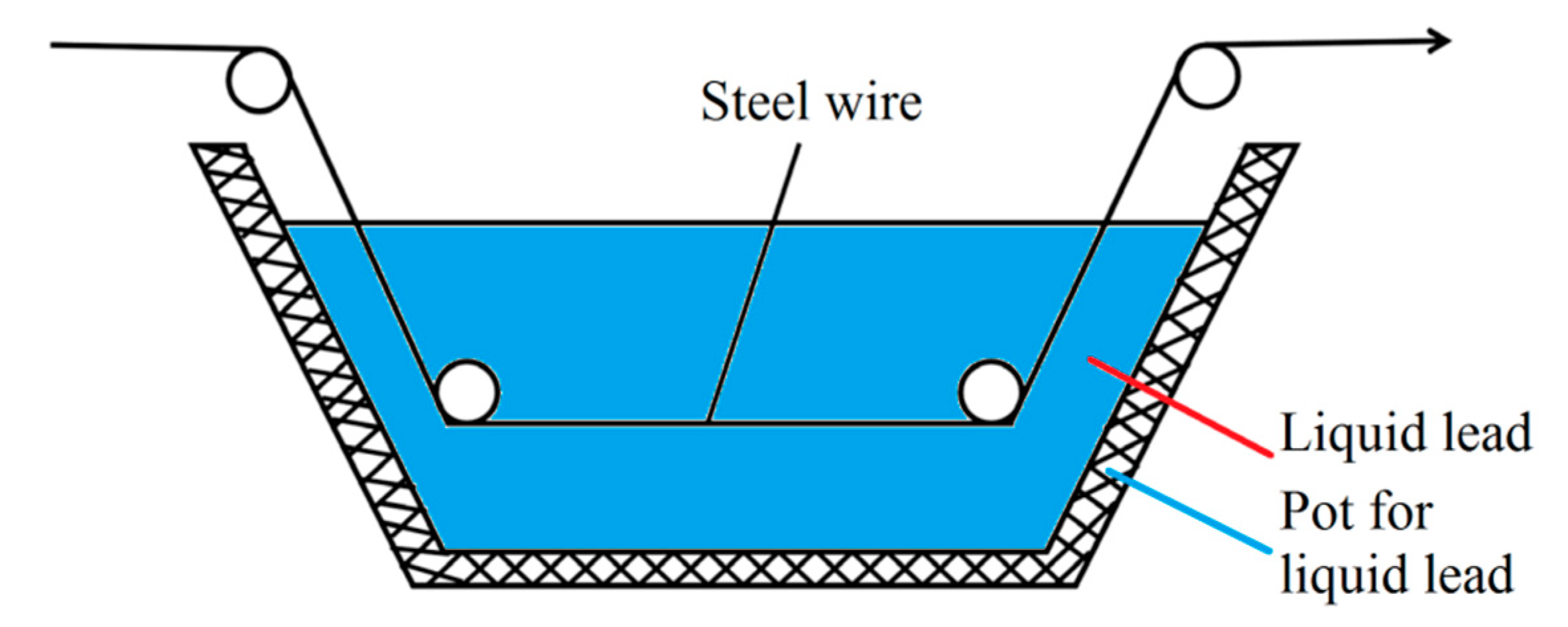
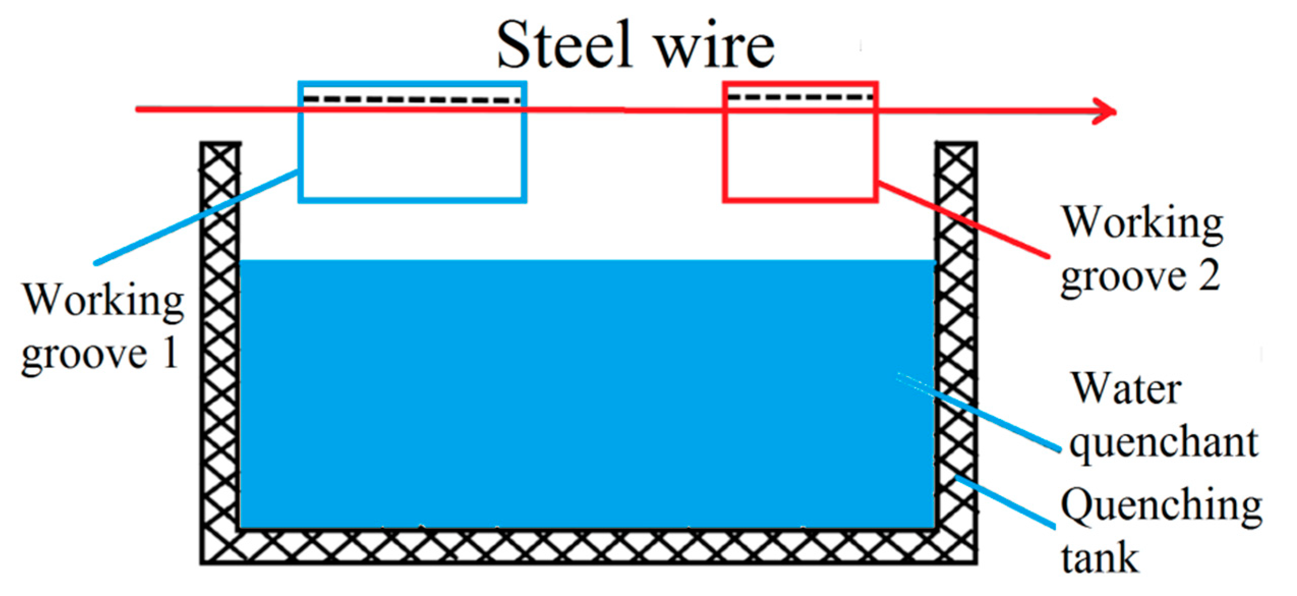
In the steel cord and saw wire drawing process, the sorbitic treatment should be performed, and the best method is a lead bath treatment. However, lead smoke and dust produced in lead bath quenching are harmful and severely pollute the environment. Considering the strict environmental protection requirements, the use of a water bath treatment was preferred over the lead bath treatment. A schematic diagram of the working devices is shown in Figure 13 and Figure 14 [22].
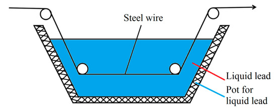
Figure 13.
Schematic diagram of the lead bath quenching of steel wire. Reprinted with permission from ref. [22].
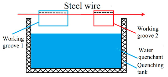
Figure 14.
Schematic diagram of the water bath quenching of steel wire. Reprinted with permission from ref. [22].
The discharge temperature of the steel wire is 850–950 °C, while the isothermal sorbiti transformation temperature is 580 °C. Complete sorbitic at 450 °C can be achieved if the transition zone from 850 to 580 °C is passed with the fastest cooling rate to prevent the precipitation of ferrite or coarse flake pearlite. Simultaneously, the temperature of the heat treatment tank is allowed to fluctuate only minimally to obtain the structure with almost the same sheet spacing. The constant temperature zone of the heat treatment bath should be long enough to ensure the complete austenitization of sorbitic in this region. Therefore, the heat treatment medium must meet the following conditions [23]:
- (1)
- In the range from 850 to 580 °C, the steel wire needs to be rapidly cooled without ferrite or coarse pearlite formation.
- (2)
- To ensure smooth quenching, the heat treatment medium should not adhere to the steel wire surface. No chemical reaction with steel wire and steel wire corrosion should occur.
- (3)
- The heat treatment medium should keep a constant temperature in the range of 400–600 °C, without changing the physical state, decomposition, and volatilization.
- (4)
- The heat treatment medium should have a large volumetric specific heat capacity, which ensures continuous heat absorption from the steel wire without a substantial increase in the local temperature, so the overall temperature will not significantly fluctuate.
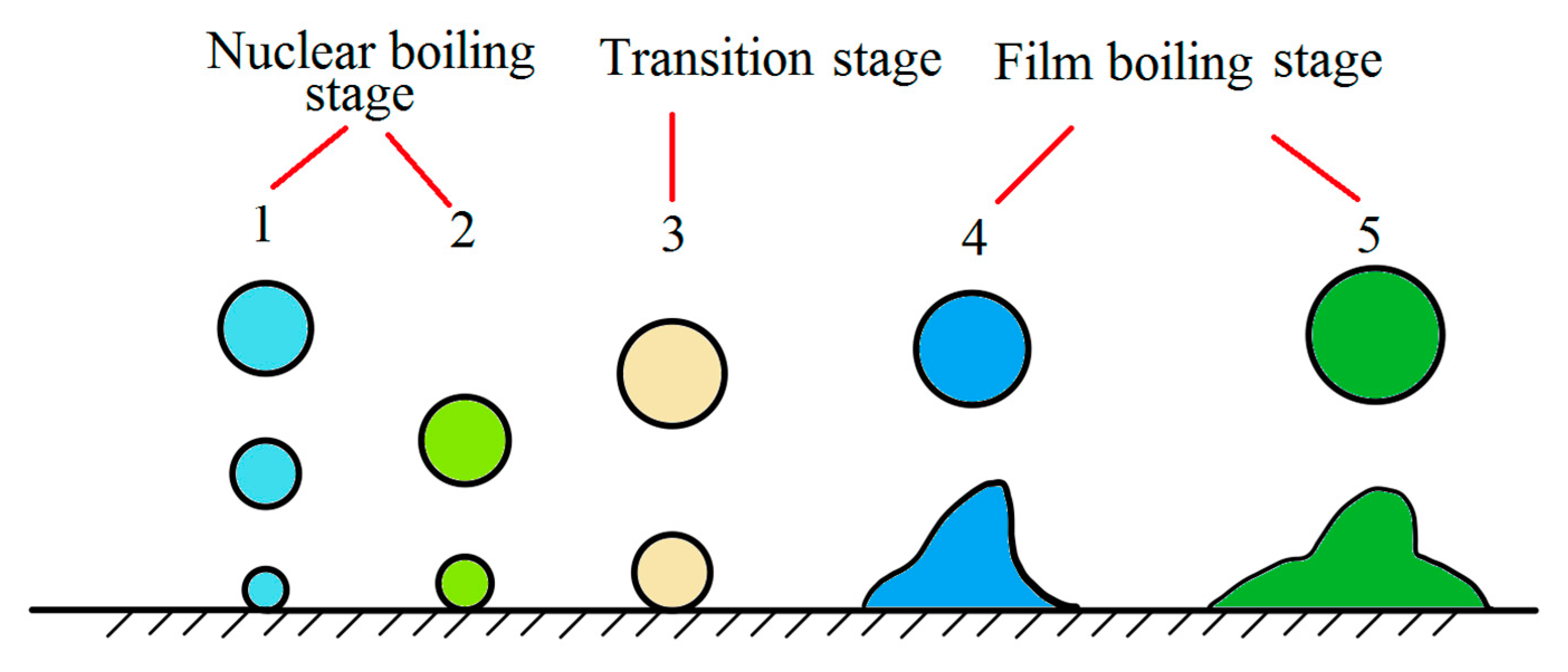
A water bath treatment of wire rod was reported already in 1942. In 1971, Chongqing steel wire rope was quenched in a boiling water bath instead of a lead bath. However, due to the limitations of water bath treatment, it could not be widely used. The basic theory of a water bath treatment assumes film boiling and nucleate boiling processes, which considers that the cooling process of high-temperature metal immersed in static water can be divided into five stages [23]:
- (1)
- Initial stage of cooling: when the steel wire is just immersed in static water, the surface temperature drops sharply, and the maximum cooling rate can reach 900 °C/s. Simultaneously, the surrounding water vaporizes rapidly and forms bubbles to prevent the steel wire temperature from further decreasing. The initial stage time generally does not exceed 1 s.
- (2)
- Stable film boiling stage: when the water around the steel wire is vaporized, the steel wire is enclosed in the steam film, which immediately slows down the cooling rate, and the cooling enters the stable film boiling stage. There are bubbles escaping from water, and the heat transfer from the steel wire mainly relies on the steam film conduction, heat radiation, and water flow around the steam film. This stage is the slowest.
- (3)
- Stable and unstable film boiling stage: also known as a variable boiling stage. The steam film is constantly broken, and more bubbles escape. Simultaneously, a new steam film continuously forms, enabling direct contact between the steel wire surface and water, and the cooling rate are significantly accelerated. When the steel wire temperature drops to a value level, the steam film on the surface completely collapses.
- (4)
- Nucleate boiling stage: in this stage, water is in direct contact with the steel wire surface and boils abruptly, forming a large number of bubbles that enhance the heat transfer effect of water convection. This stage has the highest cooling rate among the five cooling stages. When the steel wire temperature is close to the boiling point of water, the bubble formation is almost completely exhausted.
- (5)
- Convection heat transfer stage: the water surface is calm, and the steel wire cools down by natural convection. The water temperature around the surface is higher than the temperature of adjacent water layers, dissipating the heat.
By monitoring the shape and size of bubbles, we can be roughly estimate the actual cooling stage (Figure 15) [23].
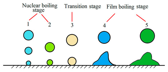
Figure 15.
Schematic diagram of steel wire water bath quenching. Reprinted with permission from ref. [23].
Xu [23] suggested three problems must be solved to replace the lead bath with a water bath for the sorbiti treatment.
- (1)
- How can we ensure a fast cooling down of the fully austenitized steel wire from the temperature range of 950–850 to the temperature range of 580–450 °C? At the same time, ferrite or pearlite should be avoided.
- (2)
- How can we ensure that the steel wire is cooled down to 400 °C without generating bainite and martensite?
- (3)
- How can we ensure the isothermal transformation of the super-cooled austenite in the temperature range of 580–450 °C and the sorbiti production with the same spacing between the plates?
According to the film boiling and nucleate boiling theory, it needs to shorten the stable film boiling stage to solve the first problem. This can be implemented with the following methods: increasing the immersion depth of the steel wire, accelerating the positioning of the steel wire, adding salt in the water to delay the traveling of steam film, shortening the time of steam film existence, etc.
To solve the second problem, it needs to extend the stable film boiling stage as much as possible. This will ensure enough time for the super-cooled austenite to complete the sorbiti transformation. The most effective method is the addition of colloidal substances, such as soap, sodium polyacrylate, and hydroxycellulose (CMC) into the water, to improve the surface tension and viscosity and reduce the fluidity of water.
Apparently, these requirements are contradictory. Historically, there were some attempts to solve the problem using a two-stage water bath [22] by adding a holding furnace after a water bath. However, the actual operational effect is not ideal: the tensile strength of steel wire after the water bath treatment is low, and the wear resistance of steel wire rope apparently reduces after the production; due to the fluctuation of processing factors, such as uneven corrosion of steel wire surface, the thickness of the oxide skin, low water temperature, concentration change, intermediate joint, and stopping and unloading line, local brittle fractures often appear in the steel wire.
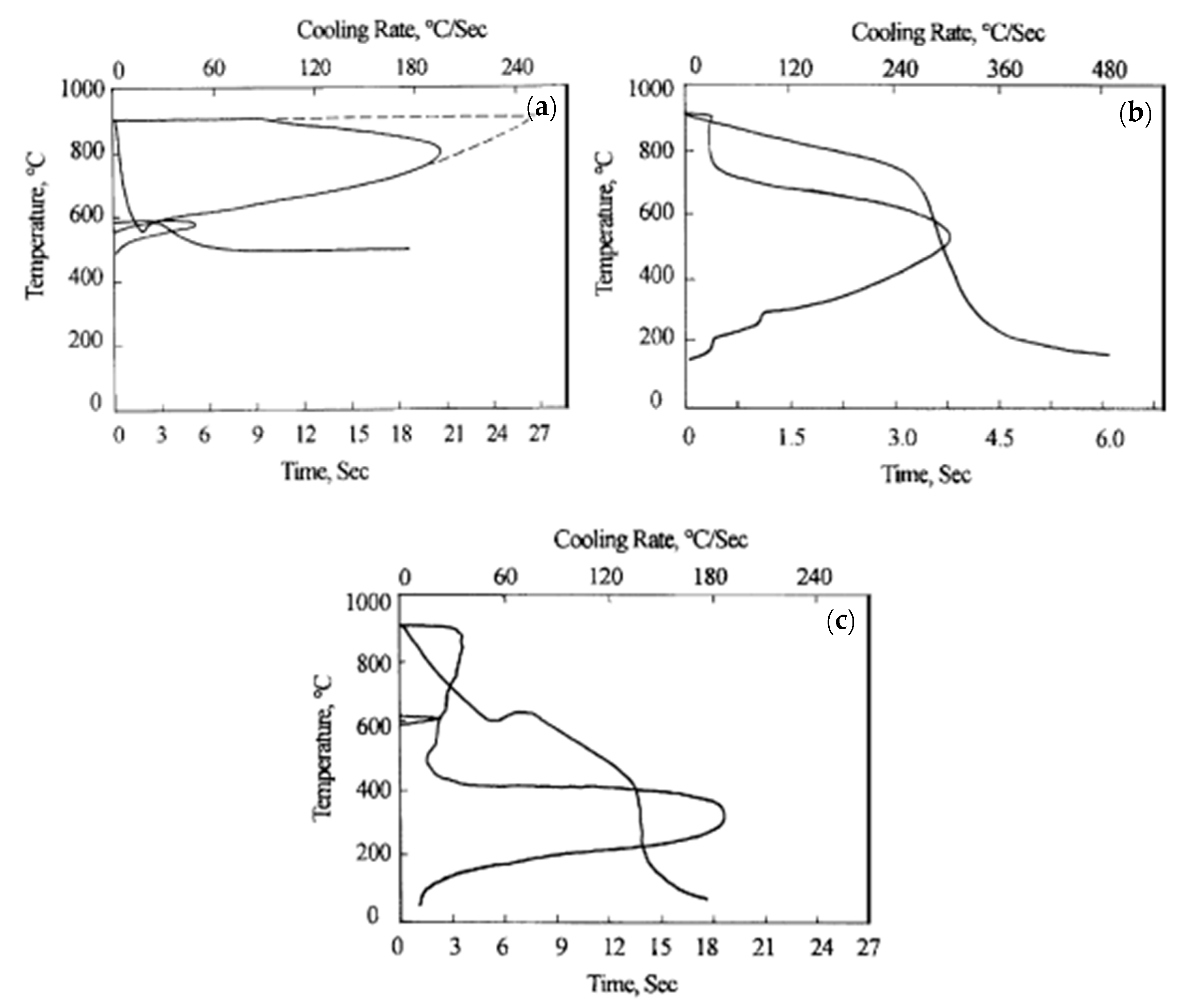
Chen and Luo [24] compared the lead bath treatment and water bath treatment of grade 70 steel wire with a diameter of 5.0 mm, as shown in Figure 16 [24]. The cooling rate and the constant temperature platform of steel wire in the CMC aqueous solution are not as good as those in the lead bath. The results of the heat treatment showed that the microstructure of the steel wire after the CMC water bath treatment consists of a small amount of pearlite, sorbiti, and some features with the mixed bainite and martensite structure, which is unfavorable compared to the full sorbiti structure after the lead bath treatment. However, other water bath media did not show particular advantages over the CMC water bath treatment.
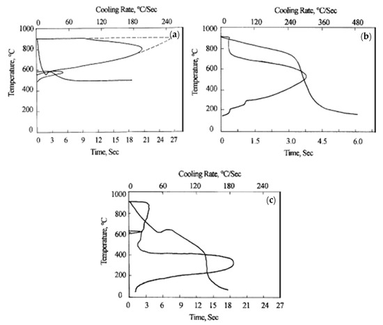
Figure 16.
Cooling rate curves of steel wire in different cooling media: (a) 505 °C, lead bath; (b) 0.10% CMC, water bath; and (c) 0.25% CMC, water bath. Reprinted with permission from ref. [24].
The water is in an unstable state in the range of 580–450 °C, so sorbiti with the same spacing cannot be obtained at all, which makes the third problem practically unresolvable at the moment.
Conclusively, the lead bath treatment is the best choice for the sorbiti treatment of the steel cord and saw wire, and for the feasible implementation of the water bath treatment, many problems need to be solved.
4. Research Progress in Copper Plating on the Steel Wire Surface
4.1. CPA Brass Plating Process
Steel cord is the main component of a tire skeleton. Actual production standards assume the embedding of the steel cord into rubber to enhance the tire strength [25]. In order to bond the steel wire and rubber tightly, the surface of the steel wire needs to be coated with a layer of Cu-Zn alloy.
The purpose of copper plating on steel cord is to improve the adhesion between steel wire and rubber. The amount of copper plating has an impact on the adhesion. Brass is generally selected as the coating, and the copper content of the coating is usually between 60% and 70%. Its Cu/Zn ratio determines the compound formula technology and coating thickness. The coating shall be uniform in color and free from scars, oil stains, rust spots, and other impurities [25].
There are two common methods of brass electroplating on steel cord—namely, the cyanide method and thermal diffusion method. Cyanidation was gradually eliminated because of its high toxicity and severe environmental and health consequences. Thermal diffusion is the most widely used method at the moment, having the following process flow [26]: the sorbiti treatment of steel wire → pre-plating Cu in a pyrophosphate system → Cu plating in a sulfate system → Zn plating in a sulfate system → thermal diffusion treatment.
According to the equipment used, there are roughly six types of conventional thermal diffusion for brass plating [27]: (1) simple electroplating of multiple steel wire equipment, (2) multiple steel wires are distributed in different electroplating tanks for electroplating at the same time, (3) electroplating of multiple steel wire equipment with a single power supply, (4) sharing power supply equipment for multiple steel wires in series in the plating bath system, (5) adopting the device for cathode surface adjustment, and (6) electroplating multiple steel wire equipment with the continuous anode surface adjustment.
Unrestricted to the equipment used, the conventional thermal diffusion Cu plating method faces many production difficulties [27]: (1) monitoring and keeping the ion concentration of a single plating section constant, (2) the deposition rate of each single plating bath (not the plating bath group) must be accurately synchronized with the continuous operational speed (speed and current density adjustment) to ensure a constant plating speed and alloy ratio, (3) avoiding damage to the wire surface due to the sliding contact system, (4) the chemical composition and temperature of the plating bath in a single bath system must be constantly monitored and maintained, (5) transferring of the plating solution must be reduced using an effective air-blowing and water-washing system to prolong the service life of the plating bath and ensure the best deposition quality, and (6) the stability and environmental protection of the equipment can be ensured by proper water washing and wastewater treatment.
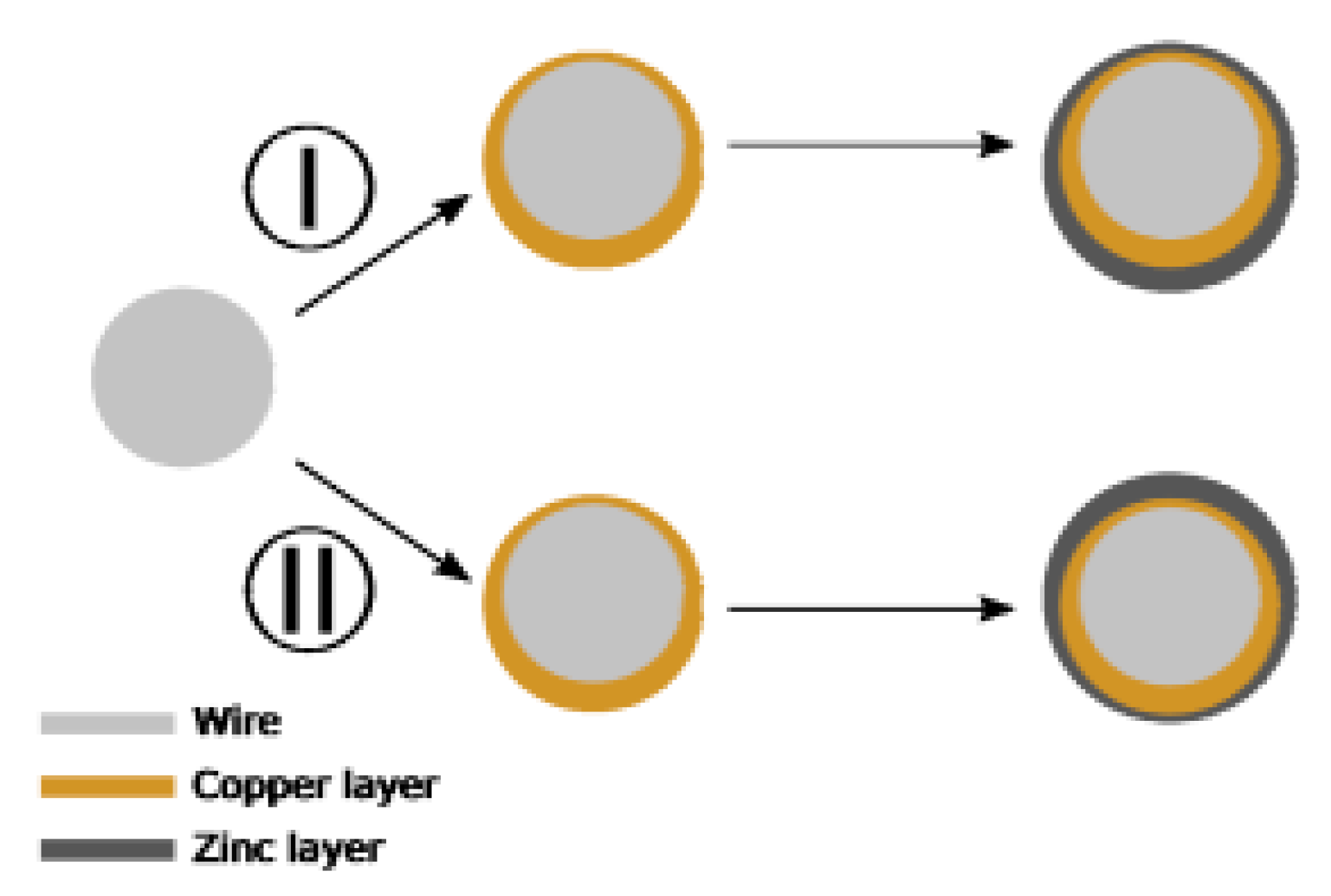
Should these problems remain unresolved, the coating structure will be seriously affected, exhibiting typical quality-related issues [28]: ununiform coating thickness, (Figure 17 (I), (II)); the change of chemical composition of brass gives β-phase brass.
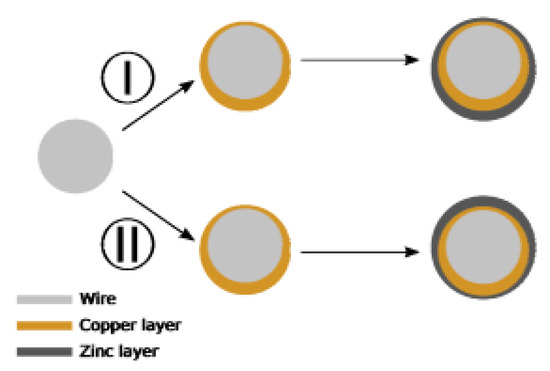
Figure 17.
Diagram of deposition deviation in the case of horizontal positive plate. Reprinted with permission from ref. [28].
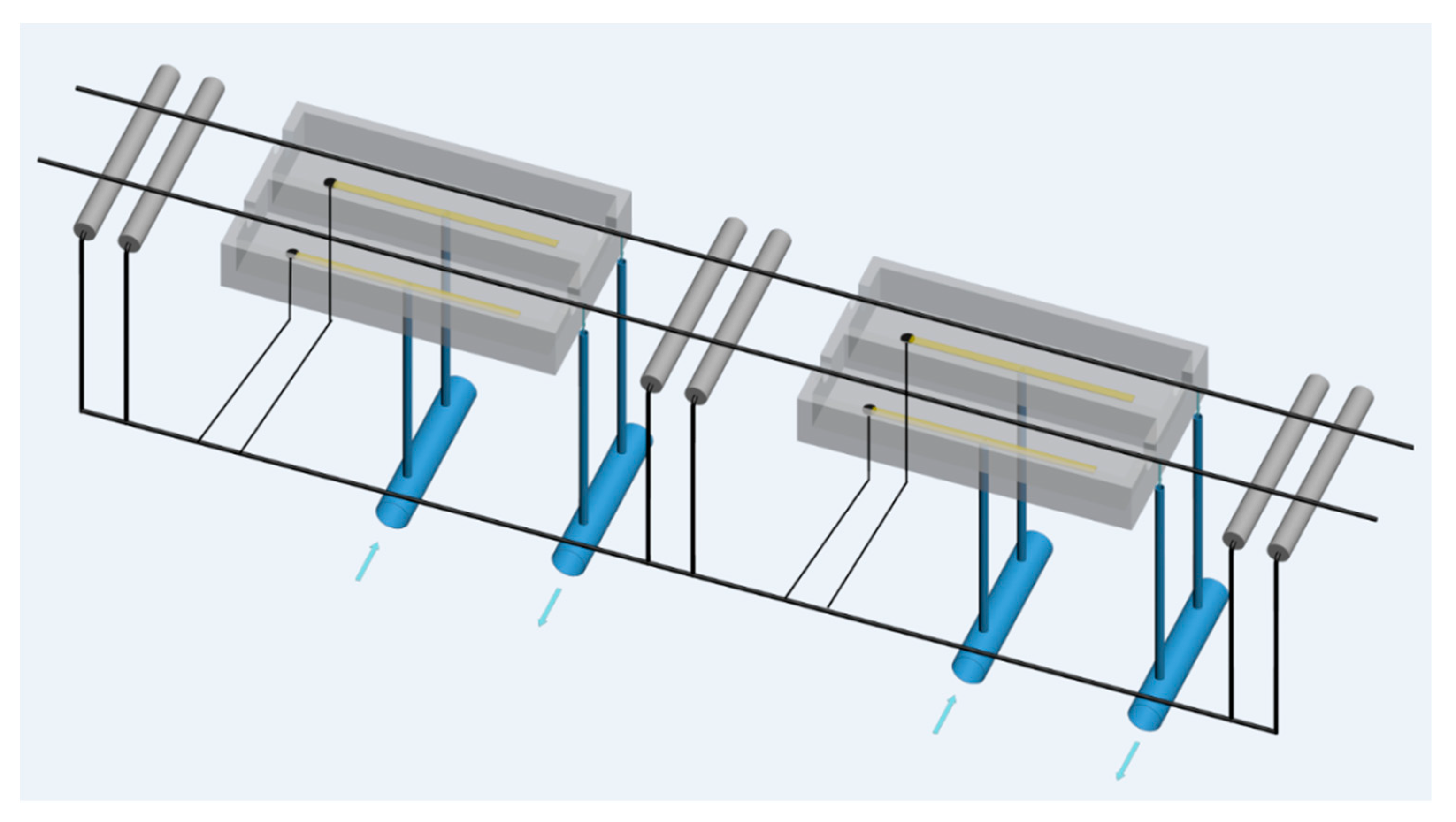
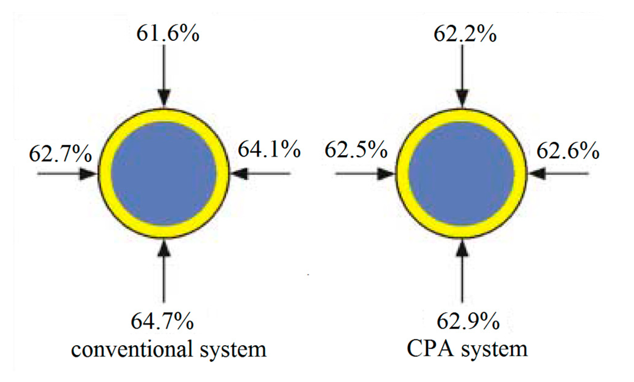
To solve these problems, Austrian company CPA Wiretec [29] developed a new electroplating system in 2006. This technology is referred to as CPA electroplating technology, and its schematic diagram is shown in Figure 18. The comparison of the thickness uniformity of steel wire coatings produced by the conventional electroplating method and the CPA electroplating method (Figure 19) shows that the CPA electroplating technology is better than conventional electroplating technology. In detail, the depth of coating structure in different position is 61.6%, 62.7%, 64.1%, and 64.7%, respectively, and the difference between the minimum and maximum values is 3.1% when the steel cord wire was treated by conventional system. However, the depth of coating structure in different position is 62.2%, 62.5%, 62.6%, and 62.9%, respectively, and the difference between the minimum and maximum values is 0.7% when the steel cord wire was treated by CPA electroplating technology.
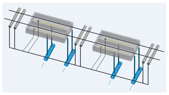
Figure 18.
Schematic diagram of the CPA electroplating process. Reprinted with permission from ref. [28].
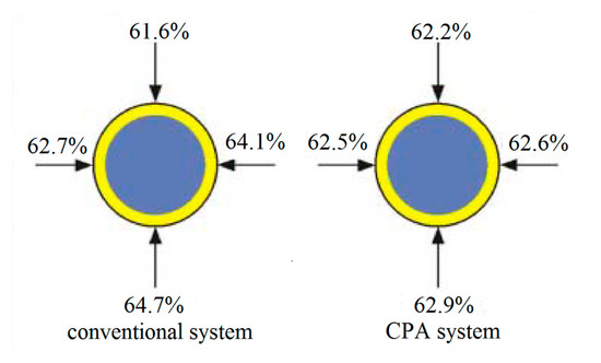
Figure 19.
Schematic diagram of the tire strap layer made of a steel cord [28].
The advantages and disadvantages of conventional copper plating technology and CPA plating technology are summarized in Table 4. The CPA electroplating technology is currently widely promoted and used, and it has become the mainstream brass plating method in the market [30,31,32,33,34,35].

Table 4.
Comparison between conventional brass plating technology and CPA electroplating technology.
4.2. Hot-Dip Brass Process
Although CPA electroplating technology has many advantages, there are still issues that need to be resolved: (1) the brass coating is electrodeposited on a steel wire, but the adhesion force is weak, so the brass coating loss rate of electroplated steel wire after drawing using a water tank drawing machine is high, and (2) there are concentration gradients of Cu and Zn in the electroplated brass layer, so the formation of the β-brass phase with high brittleness is high, which makes steel wire prone to breakage during drawing in the water tank drawing machine [36].
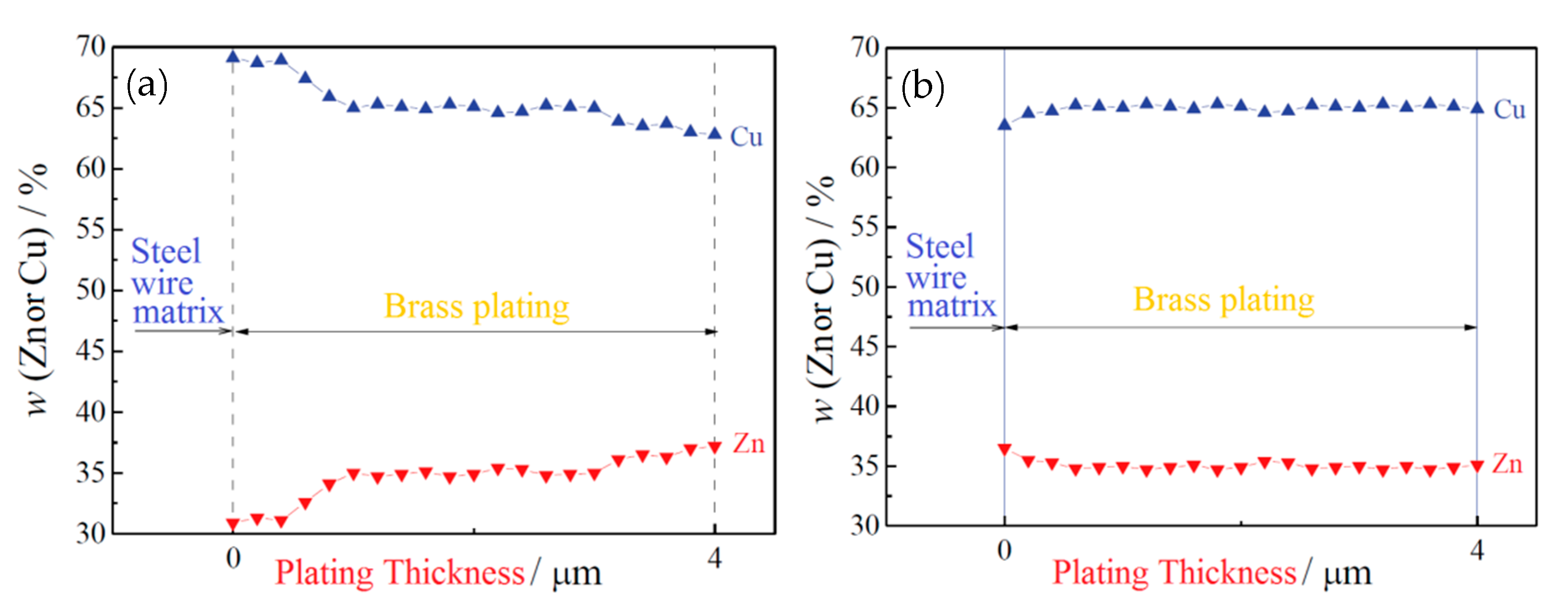
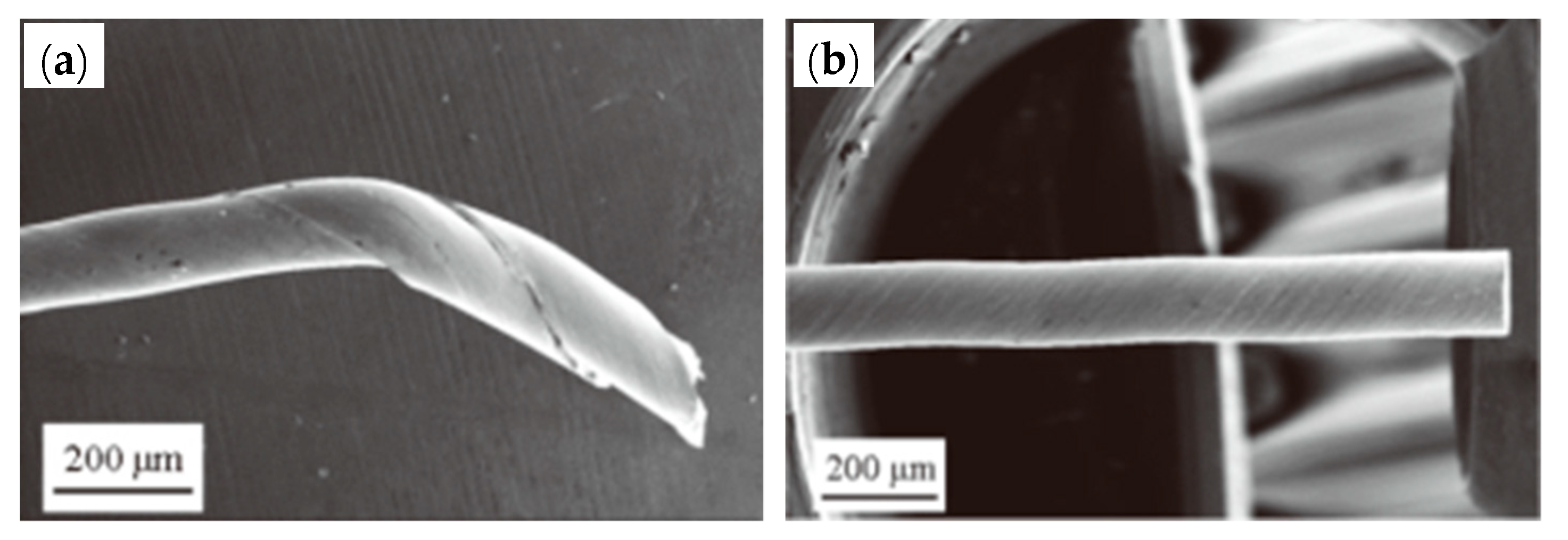
W. F. Yang et al. [36] suggested the hot-dip brass method to resolve these issues in 2018. The specific process flow of the hot-dip brass method is: after auxiliary plating, the steel wire was immersed in a molten brass solution at 980 ± 10 °C (63.5% ± 1.0% Cu) for 40–50 s and then air-cooled to room temperature. A phosphoric acid bath added after the brass plating bath for cleaning prevents ZnO film formation on the steel wire surface. Comparing the two copper plating methods, the hot-dip brass plating method was better than the electroplating method, because: (1) the concentration gradient of Cu and Zn in the coating was smaller than the electroplating method (Figure 20), (2) the thickness of the coating was more uniform, (3) the wire breakage rate was lower in the cold drawing process, and (4) the delamination fracture was reduced during the torsion tests (Figure 21).
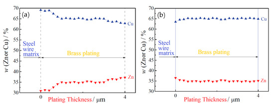
Figure 20.
EDX line scans results for (a) electroplated and (b) hot-dip plated brass coating on steel wires. Reprinted with permission from ref. [36].
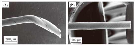
Figure 21.
Fractures of steel wire in torsion: (a) galvanized steel wire and (b) hot-dip galvanized monofilament. Reprinted with permission from ref. [36].
Yang et al. [36] suggested that the heating mode of steel wire and the formation mode of the brass layer are the main reasons for the different properties of electroplated and hot-dipped brass steel wire. Electroplated steel wire is directly but unevenly heated by flame spraying, while during hot-dip galvanizing, the steel wire is heated in molten brass at a uniform temperature. This ensures the microstructural uniformity after steel wire strengthening and toughening, such as the fluctuation range of pearlite lamellar spacing becoming smaller, and the hard and brittle phases such as pre-eutectoid cementite in the microstructure disappearing; these changes improve the cold drawing properties of steel wire [36]. Besides, there is a thermal diffusion bonding force between the hot-dip brass layer and the steel wire substrate. Intermetallic compounds are generated at the interface of the two layers, which improves the coating adhesion, eliminates the change gradient in the Cu and Zn contents in the coating, avoids the formation of hard and brittle phases, and improves the coating’s plastic deformation ability.
Hot-dip Zn plating was extensively used for a long time in steel wire coating technology, such as hot-dip Zn plating for bridge cable steel wire. However, the hot-dip Cu plating was not used in the production of steel cord and saw wire until 2018, and related reports are scarce. The potential applications in industrialization require a thorough experimental verification.
4.3. Development of New Coating Materials
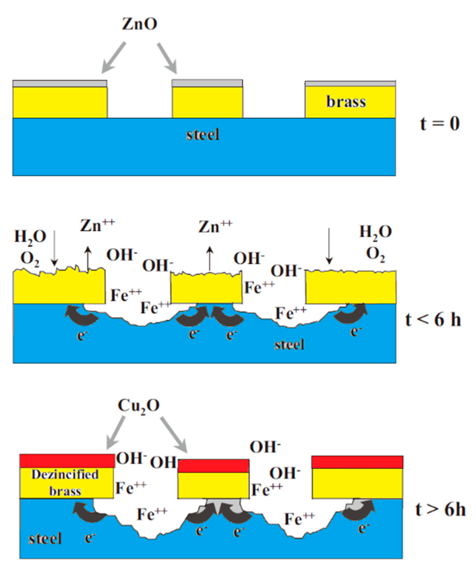
The most widely used coating material in the steel cord and saw wire production is the Cu-Zn alloy (the mass fraction of Cu is a 60-70 mass%, face-centered cubic crystal structure). It plays a lubricating role in the wet drawing process of steel wire and promotes the adhesion between steel wire and rubber. This coating material has been used for decades, but it has many disadvantages [37]: (1) at a low pH value, brass behaves as a steel cathode, which accelerates the corrosion of steel matrix; (2) at a high pH value, brass corrodes and decomposes via dezincification, which seriously weakens the bonding effect between steel cord and rubber; and (3) the adhesion between brass and rubber quickly degrades in the presence of amine compounds. The corrosion mechanism of brass-coated steel wire is shown in Figure 22 [38].
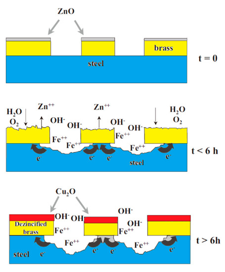
Figure 22.
Schematic representation of the corrosion mechanism of brass-coated steel wire (corrosive medium: 0.25-M Na2SO4 solution). Reprinted with permission from ref. [38].
To improve the bonding between the Cu-Zn alloy-coated steel cord and rubber and reduce the adhesion degradation rate (especially aging under conditions of high temperature and humidity), Co salt is added to the rubber compound in the actual production. This standard method has been used for more than 60 years. However, there are many shortcomings [39]: (1) Co salt is a co-oxidant, which can accelerate the aging of a vulcanizate, so it is called “rubber poison”. (2) Co salt can accelerate the rubber crack growth rate. (3) Co is an expensive strategic material. (4) The Co utilization rate is low, and only about 20% of Co in rubber promotes adhesion between the steel cord and rubber compound.
These problems directed researchers toward new coating materials [40,41,42,43,44,45,46,47]. At present, there are four kinds of new coating materials: Zn-Ni/Zn-Co alloy, Zn-Co alloy, Zn-Mn alloy, and Cu-Zn-Co ternary alloy.
4.3.1. Zn-Ni/Zn-Co Alloy Coating
In 1991, Giridhar [48,49,50,51] applied Zn-Ni/Zn-Co alloy coating to a tire steel cord. He compared the properties of (Ni-22 wt% Zn)/(Zn-5 wt% Ni), (Ni-Zn)/(Zn-Co), and Cu-Zn coatings. The corrosion resistance, dezincification resistance, and adhesion to the rubber of the (Ni-Zn)/(Zn-Co) alloy coating were optimal, so it can be used as an excellent material to replace Cu-Zn coating.
- (1)
- The as-deposited (Ni-22 wt% Zn)/(Zn-5 wt% Ni) coating cracking close to the steel wire surface and far from the rubber surface, indicated that the coating structure was not uniform. After the moisture aging test of the cold-rolled coating, the cracking became more irregular. In contrast, the plane became uneven compared with the previous one, indicating poor bonding between the coating and rubber.
- (2)
- The deposited Cu-Zn coating results had cracks completely in the rubber, and the cracking surface was uneven. After wet aging of the cold-rolled coating, the cracking pattern occurred simultaneously between the coating and rubber, and the cracked surface was not smooth.
- (3)
- The as-deposited (Ni-Zn)/(Zn-Co) coating had cracks in the center of the rubber. The cracked surface was very smooth, indicating that the coating and rubber were closely bonded, with good microstructural uniformity. After the moisture aging test of the cold-rolled coating, the cracks occurred only in the rubber and deviated from the central line, but the cracking surface was still smooth.
Thus, Giridhar et al. [50] suggested a (Ni-Zn/(Zn-Co) alloy as an optimal coating material, which could most likely replace Cu-Zn coatings.
However, the high price of Ni hinders its wide use. There is no related product on the market.
4.3.2. Zn-Co Alloy Coating
In 1998, Cipparrone et al. [52] developed a new type of Zn-Co alloy coating, where the Co content did not exceed 2.0 wt%, which exhibited a better corrosion resistance and adhesion to the rubber than a conventional brass coating. In detail, the two kinds of steel cord coated with a Zn-Co alloy and Cu-Zn alloy were bonded with rubber, and then, the extraction force was tested. The results showed that the extraction forces of the two were about 800 N and 600 N, respectively, indicating that the steel cord coated with Zn-Co alloy had a good adhesion effect with rubber.
Ten tons of 1.60-mm Zn-Co-coated (0.5 wt% Co, 2.0-μm thick) steel cord were produced and were corrosion and adhesion tests. All properties meet the required product standards. Outdoor experiments showed that the adhesion between the Zn-Co-coated steel cord and rubber was similar to the brass-coated steel cord after driving 12,000 km.
However, there were no further reports or Zn-Co-coated steel products available in the market in the last 20 years.
4.3.3. Zn-Mn Alloy Coating
The Italian tire company Pirelli developed coating materials to replace brass [53]; among which, the most potential exhibited a Zn-Mn alloy [54] (Mn is 0.3-5 mass%) developed around 2003. M. Cipparrone et al. from Pirelli [54] showed that the corrosion resistance of the Zn-Mn-coated steel cord in a 4% NaCl solution at 20 °C was several times higher than the Cu-Zn-coated. In contrast, it also exhibited better strength than a pure Zn coating.
Cipparrone et al. [54] found that the excellent corrosion resistance of the Zn-Mn coating originated from the generation of Mn2O3, MnO, and Mn3O4 on the surface of the coating, which effectively prevented corrosion. Furthermore, the mechanical strength of the Zn-Mn alloy-plated steel cord was higher than the Cu-Zn alloy-plated steel cord after aging in the high-humidity environment, as shown in Figure 23 [55].

Figure 23.
The breaking load drop of Zn-Mn and Cu-Zn-coated steel cord after aging in the high-humidity environment: (a) 2 + 3 × 0.28, (b) 2 + 1 × 0.28, and (c) 0.22 + 6 + 12 × 0.20 (different numbers indicate the combination mode of the steel cord). Reprinted with permission from ref. [55].
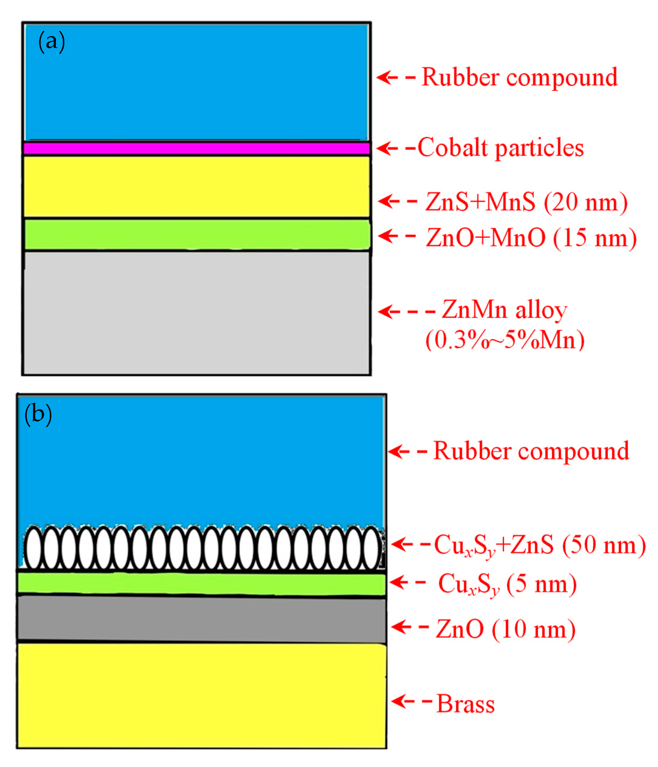
The adhesion of the Zn-Mn-plated steel cord was slightly lower than that of the Cu–Zn-plated steel cord before aging. Still, it was significantly higher after aging, indicating excellent adhesion properties. The adhesion mechanism between these two kinds of steel cords and the rubber compound is shown in Figure 24 [54].
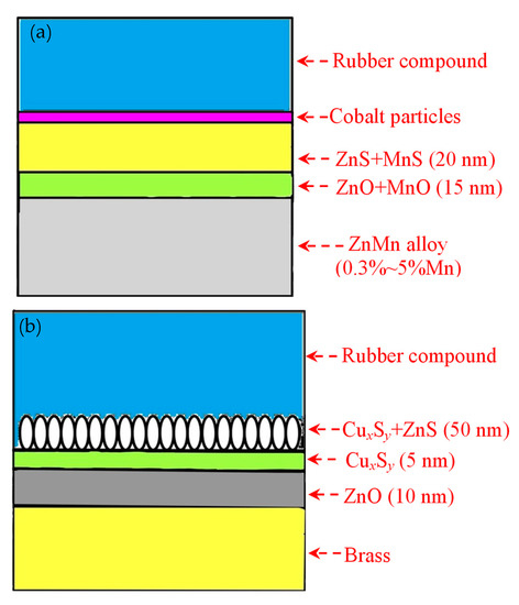
Figure 24.
Schematic diagrams showing the adhesion mechanism between steel wire coating and rubber compound: (a) Cu-Zn alloy coating and (b) Zn-Mn alloy coating. Reprinted with permission from ref. [54].
A pilot study of Zn-Mn-coated steel cord production was conducted in a Chinese factory, showing excellent experimental results. Cipparrone et al. [54] suggested that the Zn-Mn alloy-coated steel cord has excellent wet vapor aging resistance, making it more suitable for countries in the Far East due to the moisture in air being very high and the weather being really cold.
4.3.4. Cu-Zn-Co Ternary Alloy Coating
In 2005, Jeon et al. [56,57] studied the Cu-Zn-Co alloy coatings, which had excellent adhesion between the Cu-Zn-Co-coated steel cord and rubber, although the mechanism was not clarified. The Bekaert company launched TAWI® tire cord reinforcement technology, presenting a technical breakthrough in 2014. This technology uses a new Cu-Zn-Co alloy coating, and Co is used only at the interface between the steel cord and rubber, eliminating the need for Co in the tire body rubber.
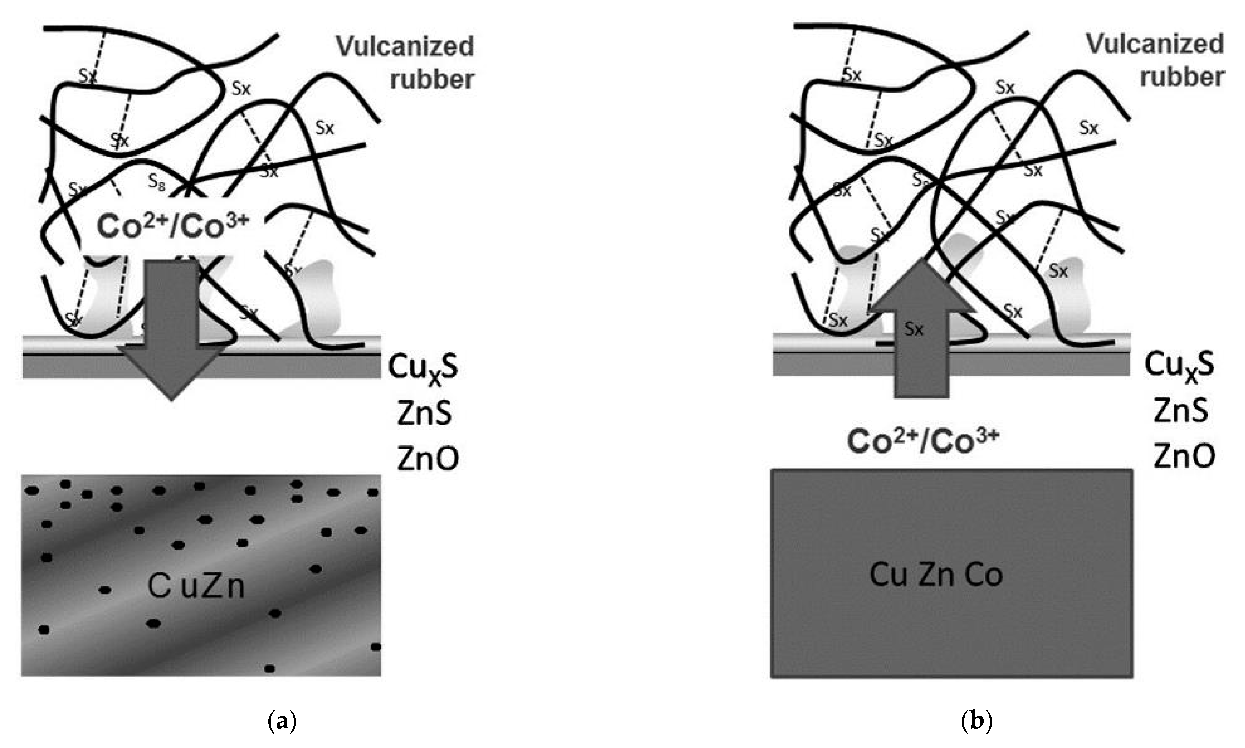
Buytaert et al. [58,59,60,61] found that the dezincification rate of the Cu-Zn-Co ternary alloy coating was lower than the Cu-Zn coating. Figure 25 shows the proposed adhesion mechanism between the steel cord with different coatings and the rubber compound [58]. The mechanical fixation between the network-shaped vulcanizate polymer and dendritic CuxS is the main adhesion mechanism. Co ions migrate from the rubber compound into the sulfur oxide interfacial layer, promoting the adhesion between steel cord and rubber. This migration path of Co ions determines that the utilization rate of Co in rubber is very low.
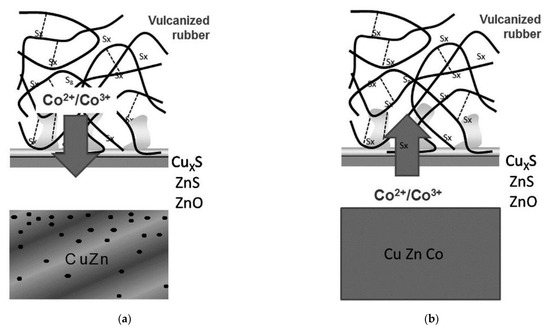
Figure 25.
Comparison of the adhesion mechanism: (a) brass-coated steel cord in a Co-containing compound and (b) Cu-Zn–Co TAWI® in a Co-free compound. Reprinted with permission from ref. [58].
However, TAWI® technology directly adds Co to Cu-Zn to prepare the Cu-Zn-Co ternary alloy, inducing Co ion migration to the interface between steel wire and rubber. Shortly afterwards, they enter the sulfur oxide interfacial layer, which promotes the adhesion between the steel wire and the adhesive and greatly improves the Co utilization rate. Since Co is no longer added to the rubber of the tire main body, it eliminates the Co-related negative effect on the rubber properties.
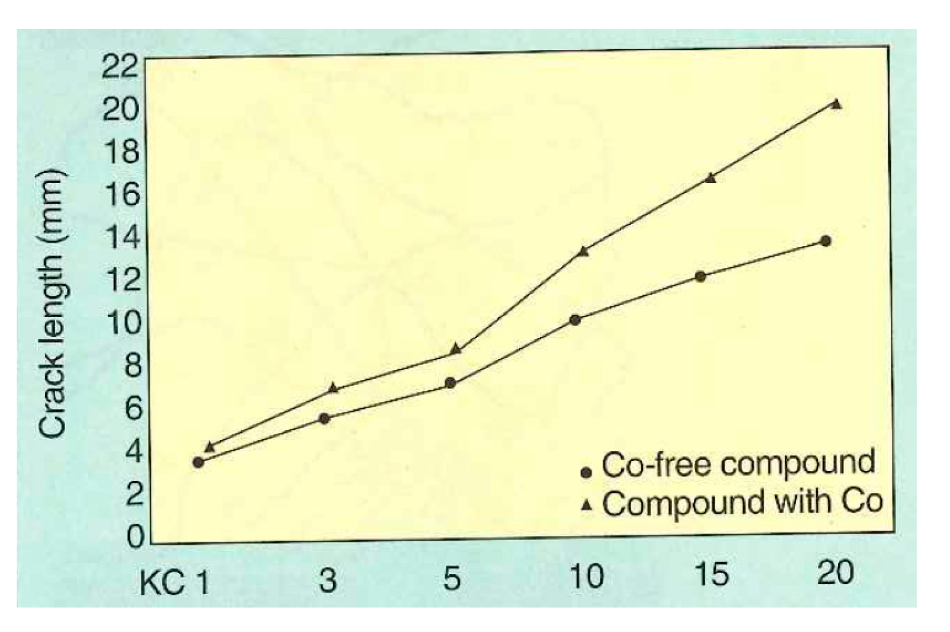
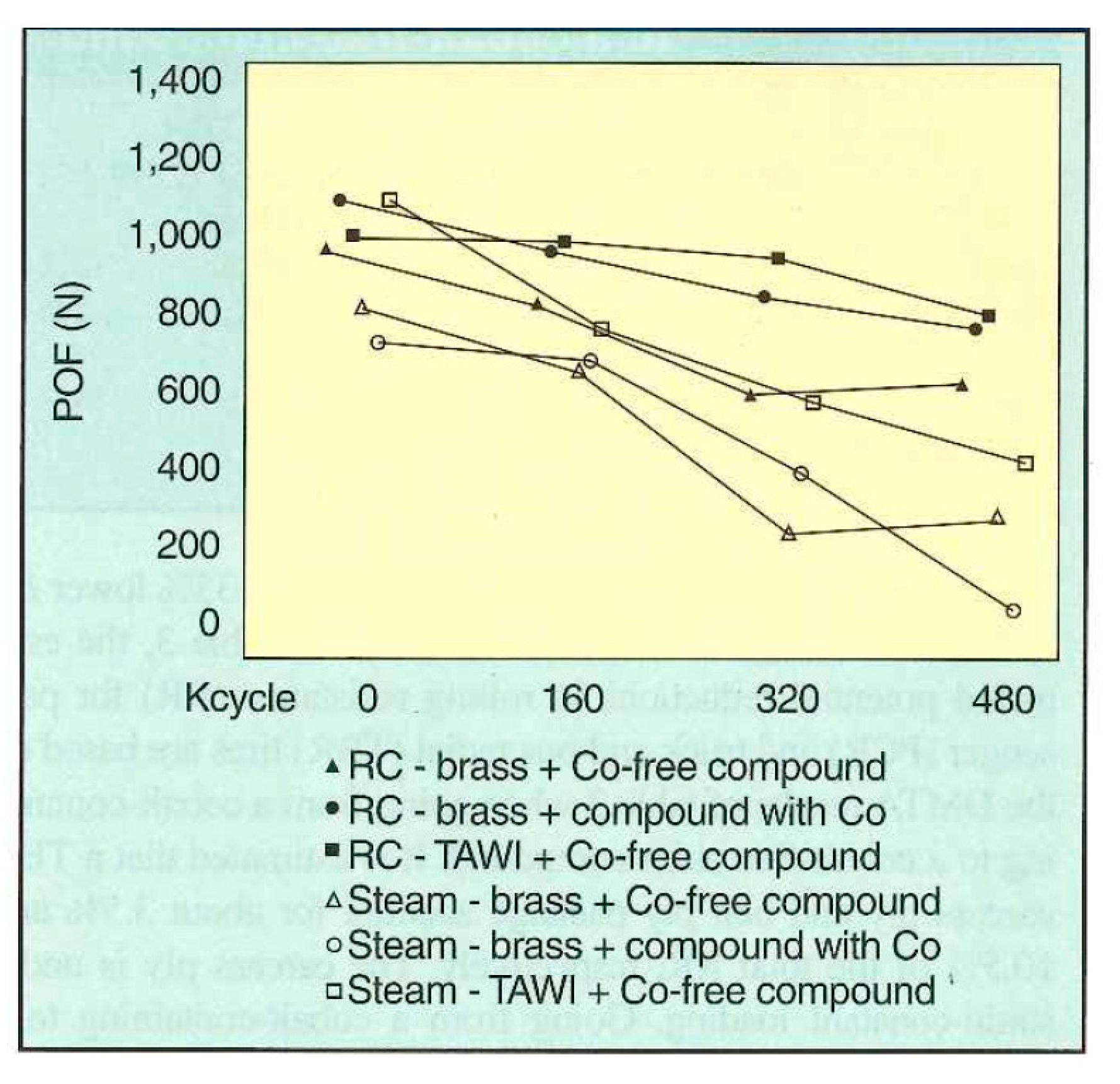
Buytaert et al. [58] performed three groups of comparative experiments on the Cu-Zn-Co and Cu-Zn systems: (1) bonding properties of the steel wire and rubber compound, (2) dynamic mechanical properties of the two materials, and (3) dynamic adhesion properties of the materials of the two systems after vulcanization and steam aging. The properties of the Cu-Zn-Co ternary alloy coating were better. The dynamic crack growth rates of the two compounds are shown in Figure 26, and the dynamic adhesion properties after vulcanization and steam aging are shown in Figure 27.
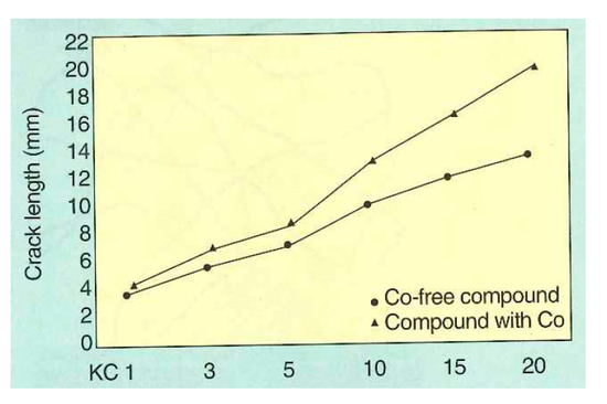
Figure 26.
Dynamic crack propagation rate of Cu-Zn-Co and Cu-Zn according to the Demattia test principle: crack length (mm) as a function of the number of flex cycles; LKC = kilocycles). Reprinted with permission from ref. [58].
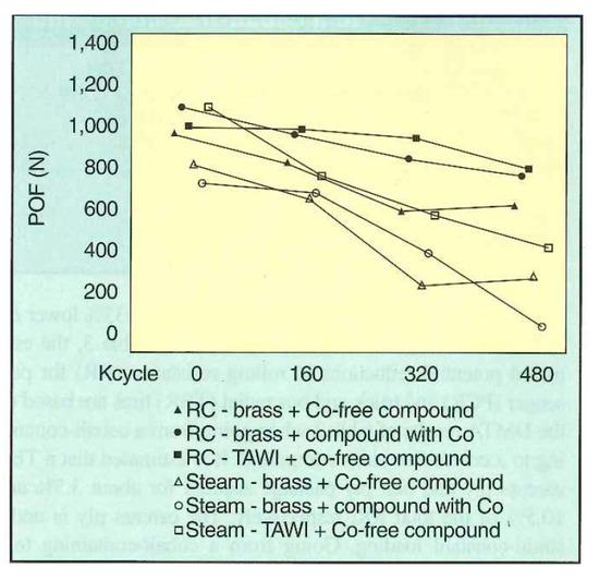
Figure 27.
POF (pull-out force) adhesion results of Cu-Zn-Co and Cu-Zn after the RC treatment (25-min cure at 150 °C) and steam aging (24 h at 105 °C). Reprinted with permission from ref. [58].
The advantages of TAWI® technology can be summarized as follows: (1) the Co consumption can be reduced by 80–90%, (2) the production process is simplified, and the environmental pollution is reduced due to the absence of Co in the compound mixing process, (3) Co-free rubber is more durable and exhibits a smaller hysteresis, (4) adhesion between the steel cord and rubber compound is better under high-temperature and high-humidity conditions, and (5) the environmental pollution caused by a scrap of Co-free tire is lower.
The Bekaert company [62] compared the adhesion performance and rubber properties of brass-coated steel cord and new-type Co-Zn-Co ternary alloy-coated steel cord. The overall performance of the Co-Zn-Co ternary alloy-coated steel cord was better than that of conventional brass-coated steel cord.
The same manufacturer also performed a laboratory loading test to better compare the adhesion properties of steel cord under high-temperature and high-humidity conditions. Hainan Island, China was selected as the test site. After eight months of use, the tire had been driven for 55,000 km. The coaxial tire with the new Co-Zn-Co ternary alloy-coated steel cord and the tire with the brass-coated steel cord had similar wear resistances.
Bekaert’s TAWI® technology is currently subjected to industrial trial production and is expected to enter the market soon.
5. Research Progress in Steel Wire Drawing Technology
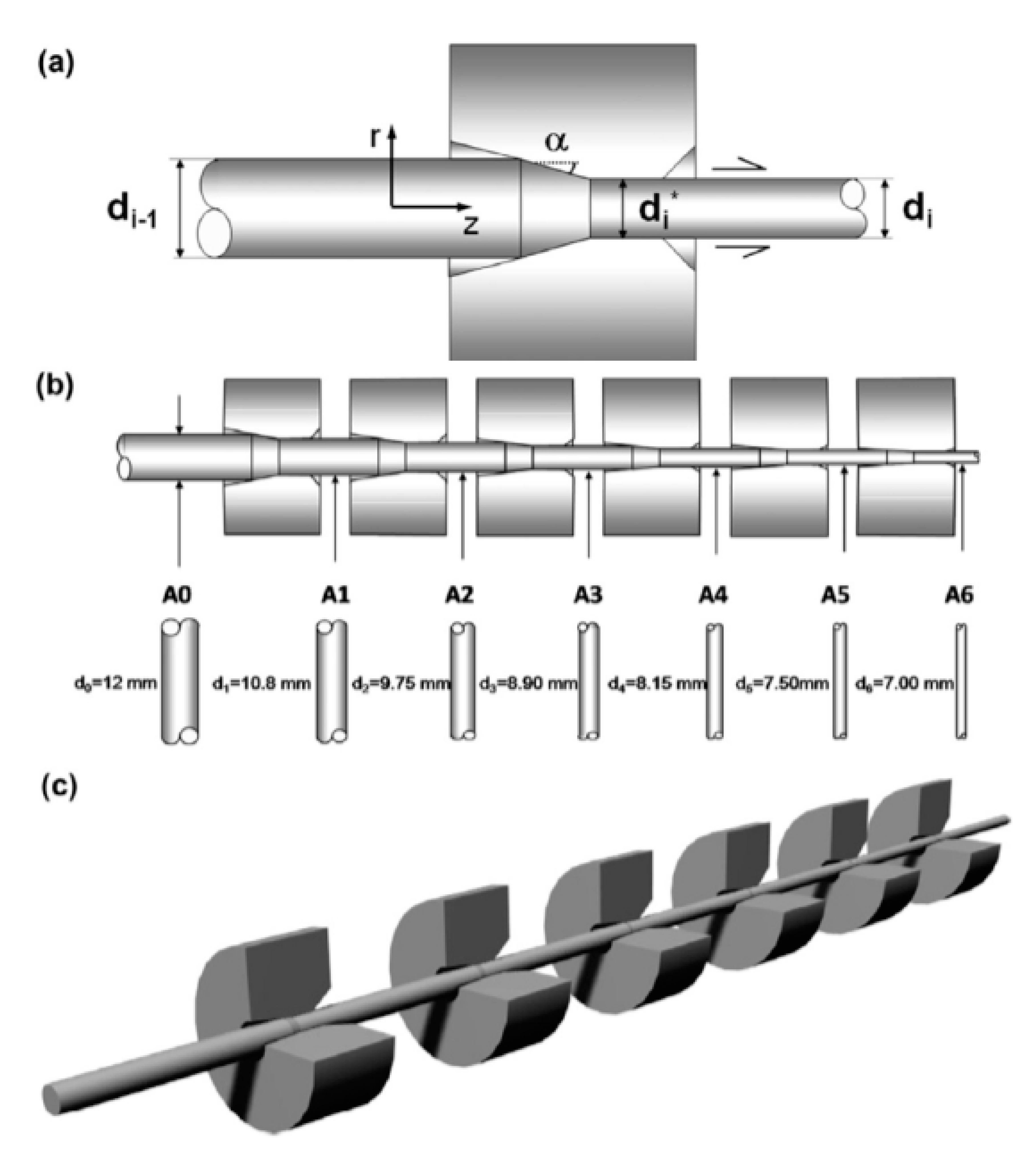
The finished steel cord or cut steel wire can be obtained only by drawing the wire rod several times. The drawing process is shown in Figure 28 [63]. The steel wire drawing process has a critical impact on its microstructure and properties, so extensive research on this topic has been performed [64].
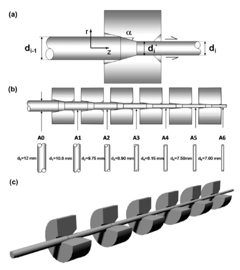
Figure 28.
Diagram of the cold drawing process: (a) single-pass steel drawing through the die (one-pass cold drawing), (b) 6-pass progressive cold drawing, and (c) whole manufacturing chain [63].
5.1. A Novel Alternative Drawing Process
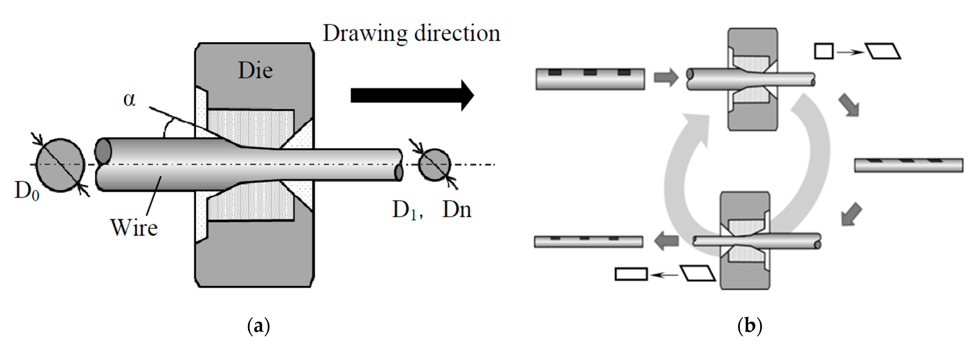
Recently, the drawing process of steel cord and saw wire has already been very well-established. In the last 20 years, research on this topic mainly focused on the optimization and improvement of the drawing lubricant [65], drawing die [66], drawing speed [67,68], and setting the compression ratio per pass [69], with no significant improvement in the drawing process. In 2016, Nagashima et al. [70] proposed a novel “alternative drawing method”. The comparison between the conventional drawing method and the novel method is shown in Figure 29. In the novel cross-table drawing method, the drawing direction of the steel wire between subsequent passes is completely opposite. It reduces the surface shear strain and improves the microstructure and properties of the steel wire.
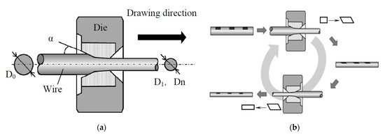
Figure 29.
Wire drawing process: (a) conventional drawing and (b) novel alternative wire drawing. Reprinted with permission from ref. [70].
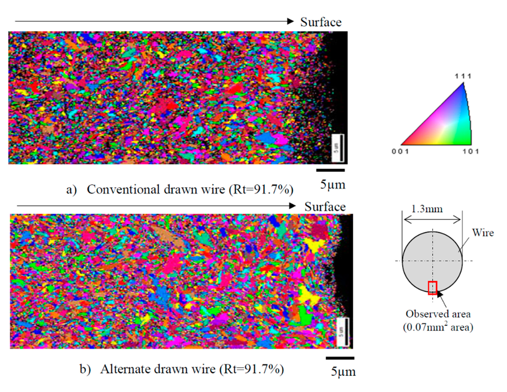
The microstructure and properties of the steel wire produced by the two drawing methods are: (1) a finite element analysis showed that the alternating wire drawing effectively reduced the total equivalent strain and hardness of the steel wire surface, and (2) tensile testing indicated that the alternating wire drawing effectively improved the plasticity of the steel wire. The tensile strength of the steel wire did not decrease significantly, although the fracture elongation and the area reduction rate increased by 24.7% and 4.7%, respectively. The difference of tensile strength between the two kinds of steel wires is very small, which is about 2300 MPa, when the drawing strain is 2.5. (3) The torsion test showed that the alternating wire drawing did not exist in delamination cracking (the total compression rate is 91.7%), and it changes into a flat fracture perpendicular to the axis. (4) The EBSD (as shown in Figure 30) demonstrated that an alternating wire drawing can effectively inhibit the compression ratio of the surface grain of the steel wire compared with the conventional wire drawing method; the average surface grain size of the steel wire produced by alternating drawing is increased by 15%. (5) The orientation of the surface grains of the steel wire produced by the alternating drawing is more random than in the case of conventional drawing.
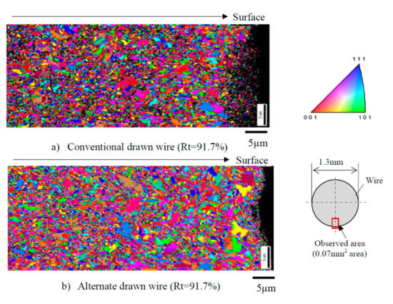
Figure 30.
Grain sizes of drawn wire (Rt = 9 1.7%): (a) conventional drawing and (b) novel alternative wire drawing. Reprinted with permission from ref. [70].
The novel alternative drawing method proposed by Nagashima et al. represents a great breakthrough with promising application potential. However, there are still many problems to be resolved before the industrial application this method. These are: (1) the change of the shape and texture evolution of pearlite in the steel wire drawing process; (2) the uniformity of ferrite deformation, dislocation density in ferrite, and the orientation of the ferrite strips have been quantitatively determined; (3) the deformation of cementite in the drawing process; and (4) the influence of microstructural changes on the rheological properties of steel wire.
5.2. Dry Drawing Process
The conventional process flow of steel cord production is given as follows: wire rod pretreatment → dry drawing (or rough drawing) → intermediate heat treatment → secondary dry drawing (or middle drawing) → heat treatment/electroplating brass → wet drawing → twisting ply [71]. Based on extensive practical research, Qian et al. [71] developed a novel dry drawing process. They used a new dry lubricating powder combined with conventional sodium-based lubricating powder to achieve direct drawing. The process flow is given as follows: wire rod pretreatment → dry drawing (or rough drawing) → heat treatment/electroplating brass → wet drawing → twisting and laminating, without an intermediate heat treatment process.
Qian et al. showed that the novel dry drawing process had many advantages [71]:
- (1)
- Improved surface roughness of dry-drawn steel wire (Figure 31), which increases the powder content on the surface of dry-drawn steel wire and the lubrication effect of the dry drawing.
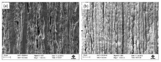 Figure 31. Surface roughness of the smooth medium-steel wire: (a) conventional process and (b) novel process. Reprinted with permission from ref. [71].
 - (2)
- Improved breaking force of the medium steel wire that did not affect the torsional properties of Cu-plated steel wire and single wire.
- (3)
- Decreased the pearlite lamellar spacing of steel wire, simultaneously improving the breaking strength and area reduction of Cu-plated steel wire. When the steel wires are dry drawn and have the same diameters, the tensile strength difference between the two kinds of steel wires is very small, which are 1165 MPa and 1175 MPa, respectively.
- (4)
- Affect on the coating, wet drawing, and twisting yield of Cu-plated steel wire, as well as the adhesion properties of the finished cord.
This novel dry drawing technology improved the production efficiency and reduced the production costs, showing considerable application potential. However, there are some disadvantages:
- (1)
- The total compression rate increases in the novel dry drawing process, and the stress variable of the dry-drawn steel wire also increases, which decreases the torsional value of the middle tension steel wire. The deterioration of the torsional properties of the steel wire must be the result of the deterioration of the microstructure, but Q. S. Qian et al. did not provide a convincing explanation.
- (2)
- Many previous studies [72,73,74,75] showed that too-high a strain in steel wire drawing may facilitate cementite decomposition in the steel wire (which may be one of the reasons for the deterioration of the torsional properties) and may lead to delamination cracking of the steel wire.
Therefore, to avoid the failure of steel wire drawing, these two problems need to be studied in detail before implementing the novel dry drawing process.
5.3. Effect of the Wet Drawing Speed on Microstructure and Properties of Steel Wire
The theory and technology of plastic deformation during the drawing of a steel cord with a C content of 0.72 and 0.82 wt% have been extensively studied, and the highest wet drawing speed reported was 20 m·s-1 [76,77,78,79,80,81]. As the C content in cord steel and cutting wire steel has recently gradually increased (the market mainstream value is 0.92 wt% C), the corresponding wet drawing speed also needs to be adjusted. However, there are only a few reports on the wet drawing of a single wire with a C content of 0.92 wt%.
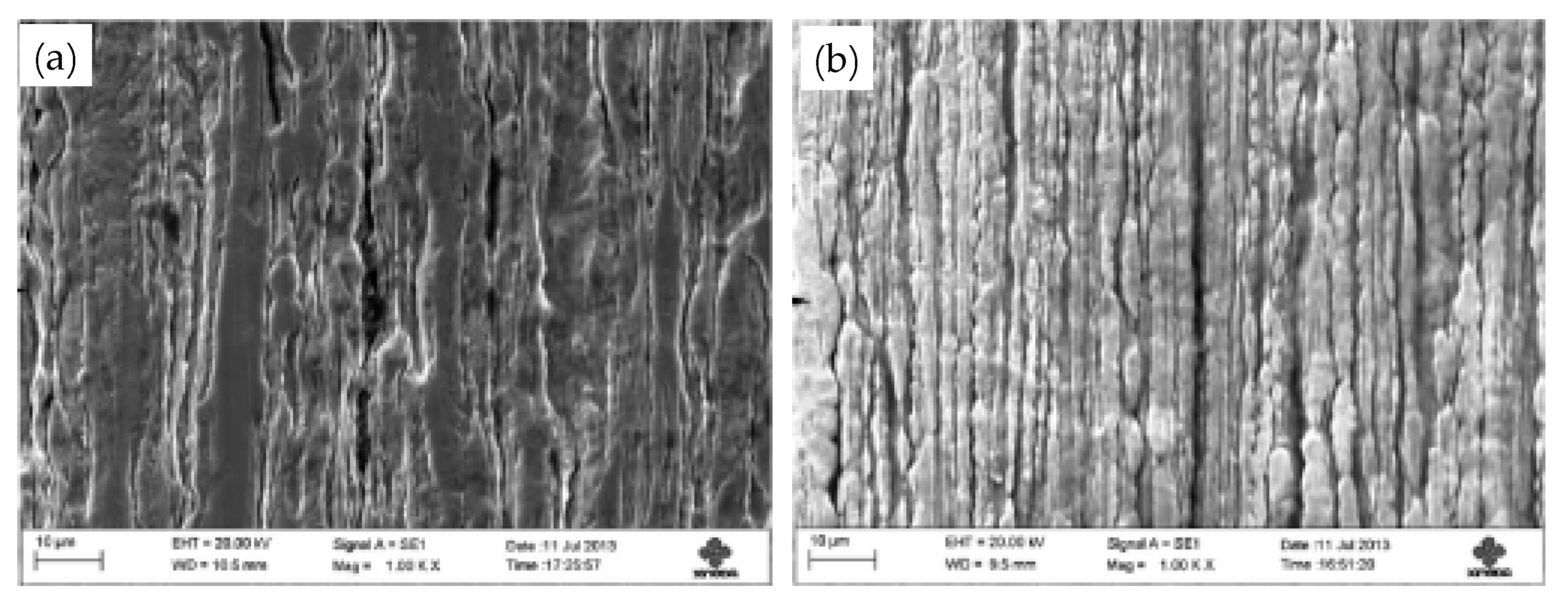
In 2002, Zelin et al. [82] studied the effect of the drawing speed on the microstructure and properties of cord steel wire and showed that the torsional properties decrease with the drawing speed. Figure 32 shows the torsional fracture morphology.
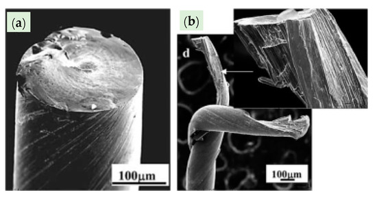
Figure 32.
Delamination behavior of the wires produced at low (a) and high (b) wet drawing speeds under torsional loading. Reprinted with permission from ref. [82].
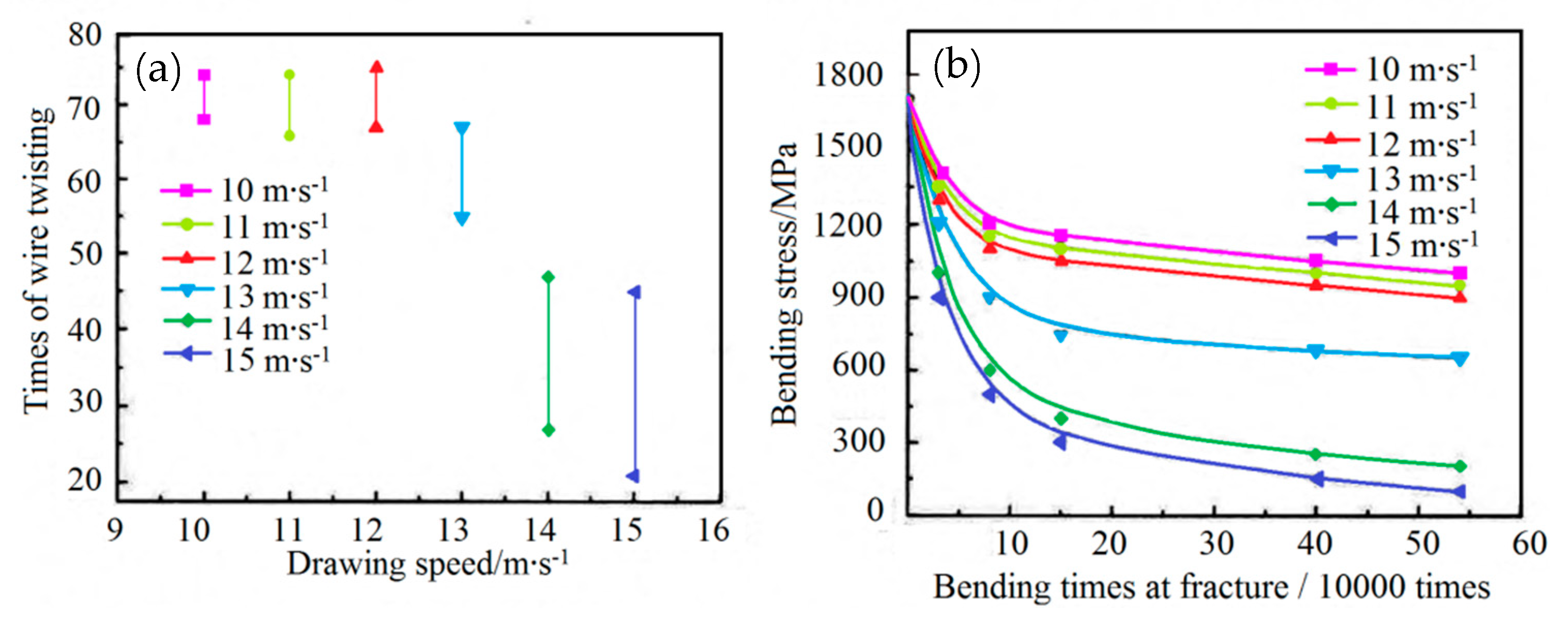
In 2015, Liu et al. [83] showed that: (1) when the wet drawing speed was higher than 13 m·s−1, delamination of the single wire occurs under torsion, and (2) the torsion times and Hunter fatigue limit of the single wire decreased with the wet drawing speed, as shown in Figure 33. The main reason for the delamination cracking of steel wire was that the generating capacity of heat of steel wire increased gradually with the wet drawing speed, while cementite dissolved. However, they did not provide any corresponding drawings and data about potential organizational changes.
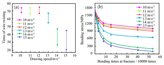
Figure 33.
Bending fatigue limits of filaments at different wet drawing speeds: (a) torsion number and (b) bending fatigue limit. Reprinted with permission from ref. [83].
Based on this research [83], Sakamoto et al. [84] studied in 2019 the influence of drawing speed on the strength and plasticity of steel wire. The steel wire strength gradually increased with the drawing speed, while the plasticity showed an opposite trend.
The above research results [83,84] provided favorable data guidance for the actual production. Still, Liu and Masashi Sakamoto et al. did not investigate the influence of drawing speed on the microstructure of steel wire, which needs to be the focus of the follow-up work.
6. Research Progress in Dies for Steel Wire Drawing
The dies used in the drawing process of steel cord and saw wire are mainly WC drawing dies with Co as the binder. There are a few recent related studies focusing on some individual problems, such as the type of binder and polishing particles of the die [66,85].
6.1. Cemented Carbide Mold
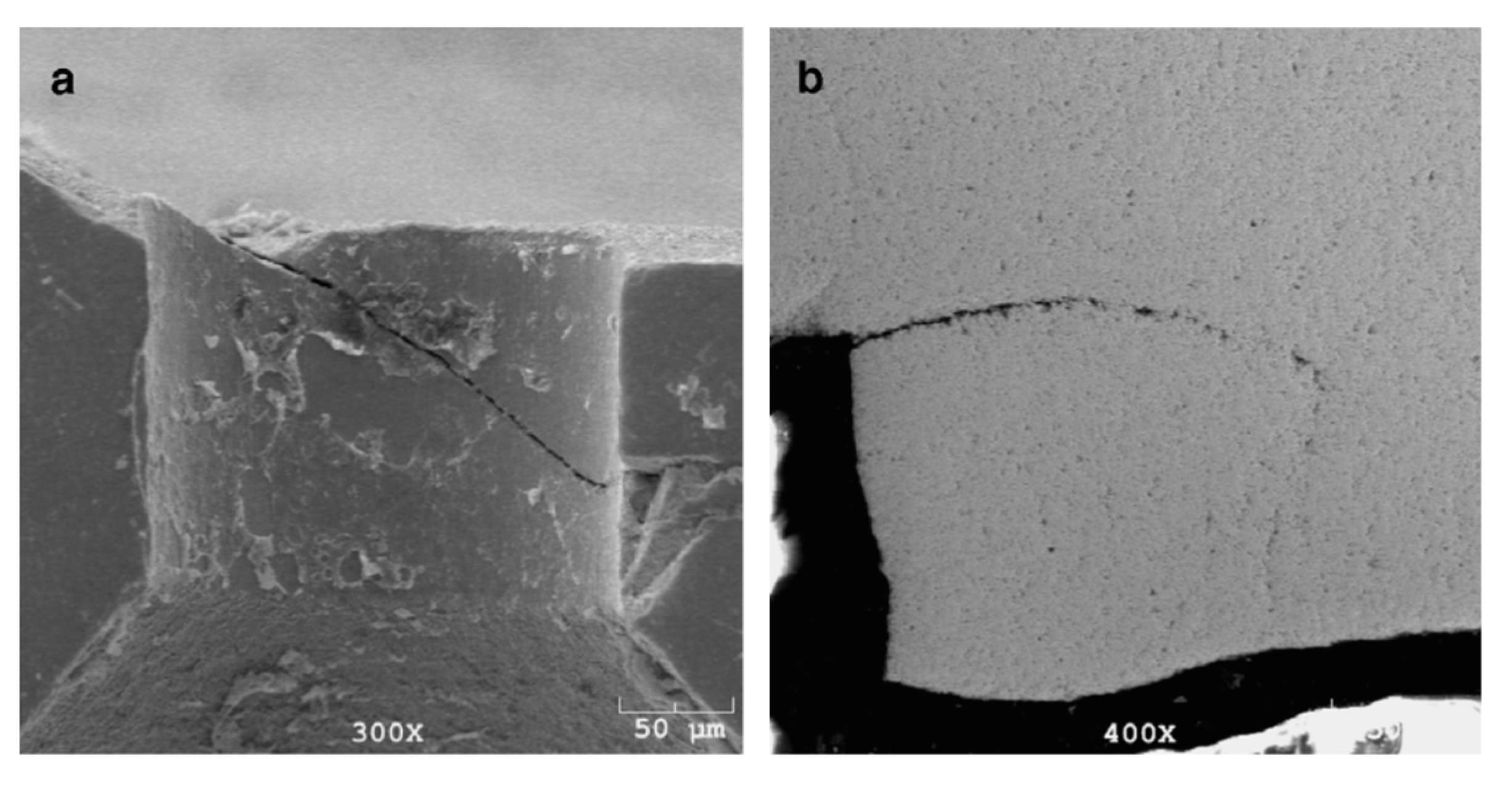
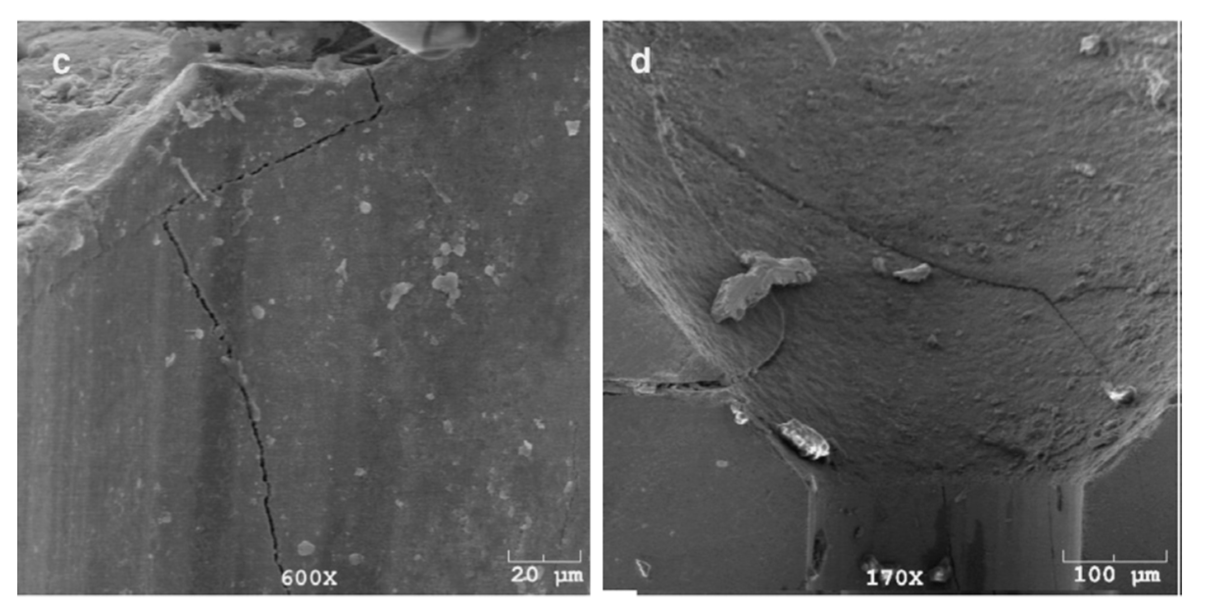
WC is a very hard material. Any damage or crack formation during the drawing of steel wire may cause two main problems: (1) the die failure, as shown in Figure 34 [86], and (2) small, detached WC particles may embed into the steel wire surface and cause its fracture.
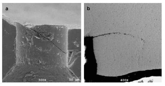
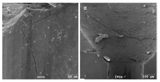
Figure 34.
Failure modes of WC–6%Co drawing dies: (a) slanted crack, (b) combination of horizontal and vertical cracks, (c) multidirectional cracks, and (d) branched cracks. Reprinted with permission from ref. [86].
Masayuki et al. [87] studied the effects of 15 different proportions of five different adhesive materials (Co, TaNbC-Co, Cr3C2-Co, VC-Co, and Cr3C2-Ni) on the properties of WC mold to develop better binders. The magnitude of the binder effect from excellent to poor was arranged in the following order: TaNbC-Co > Cr3C2-Co > Co > VC-Co > Ni. The WC drawing die produced with the TaNbC-Co binder exhibited the smallest grain size, the highest density, and the best wear resistance.
A smooth surface will alleviate the friction between the steel wire and the die, and thus, the probability of die damage and wire fracture during drawing will be lower. Lee and Ko [88] investigated the effect of diamond abrasive grains with a particle size of 2–4 μm and 8–10 μm on the surface roughness of the WC drawing die. The results showed that diamond abrasive grains with a smaller diameter yield a smoother surface of the WC drawing die, as shown in Figure 35.

Figure 35.
Die surface according to the size of the abrasive grains (as observed by SEM): (a) abrasive size 2–4 μm; (b) abrasive size 8–10 μm. Reprinted with permission from ref. [88].
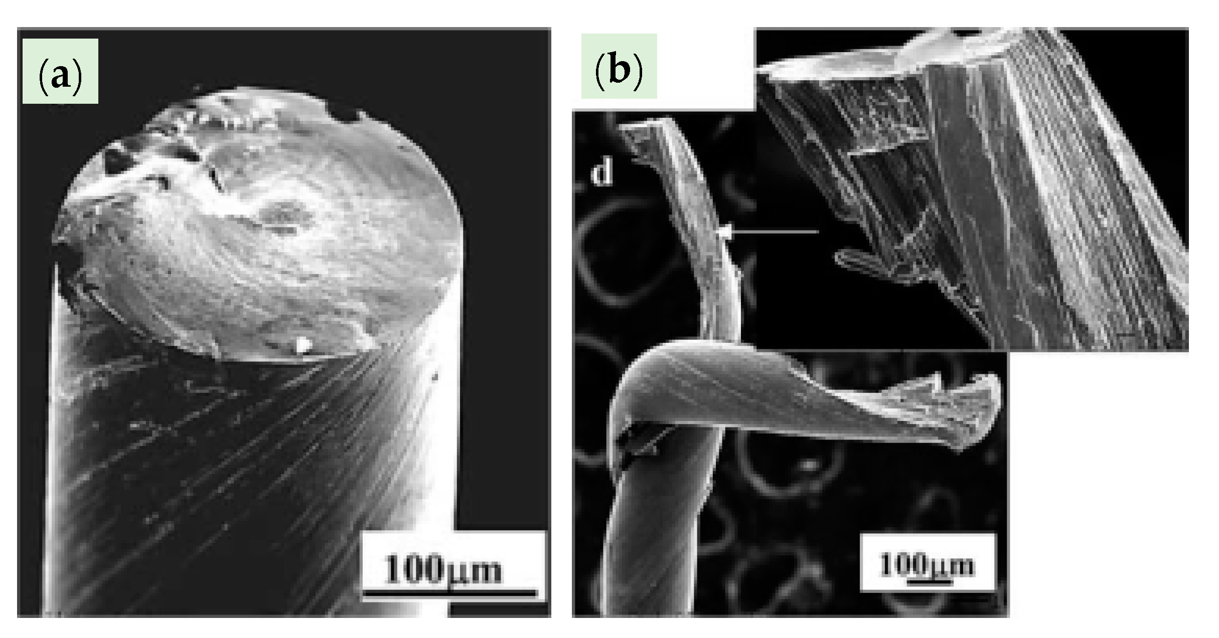
The smoother surface of a WC die will provide a longer service life, lower failure and breakage rates of the WC die, high drawing efficiency, and a lower breakage rate of the steel wire. When a WC drawing die is polished by 8–10-μm diamond abrasive grains, the steel wire will undergo fracture because of the embedded hard WC particles on the surface, as shown in Figure 36.

Figure 36.
Die failure and steel wire fracture during steel cord drawing: (a) mold failure, (b) mold damage, and (c) steel wire with WC particles embedded in the surface. Reprinted with permission from ref. [88].
Due to the mold made of cemented carbide material prepared by sintering and hot isostatic pressing, there is still a risk that the particles embedded in the steel wire after the mold is broken during the drawing process, resulting in the fracture of the steel wire. Therefore, when cemented carbide is different from abrasive tools, what needs to be studied in the future is how to further improve the bonding effect of mold materials in order to reduce the probability of breakage.
6.2. Natural Diamond Mold
To reduce the wire breaking rate in steel wire drawing, new wire drawing dies are developed. Diamond drawing dies have achieved good results and industrial applications [89]. Their main characteristics are [89]: (1) the best wear resistance and thermal conductivity; surface quality, performance, and dimensional accuracy of wire material can be improved during wire drawing, and (2) the disadvantage of this type of mold is its high cost. Additionally, natural diamond is brittle, having low impact resistance and anisotropic hardness. These issues make a natural diamond die easy to be elliptical due to uneven wear. Furthermore, if the tensile stress is too large, the drawing die will break. Therefore, the natural diamond die is mainly used as a die for the final sizing of the steel cord and saw wire.
6.3. PCD Diamond Mold
Polycrystalline diamond (PCD) was successfully synthesized by Japanese scientists [90] in 2010. PCD consists of many single-crystal particles without directional polymerization, having high strength, strong impact resistance, uniform properties, and good comprehensive performance. When drawing fine wire, its service life is higher than that of a natural diamond mold and cemented carbide mold, providing a stable size of wire and good surface quality. However, synthetic PCD has many shortcomings [90]: (1) the grain size is larger, and (2) the surface finish of the drawn filaments cannot be compared with that of a natural diamond. (3) Since PCD is made by sintering of diamond single-crystal particles and the binder, thermal expansion and cold shrinkage due to the temperature change during the drawing process will cause deformation inside the mold, accelerating the mold wear.
6.4. CVD Diamond Mold
Chemical vapor deposition (CVD) diamond is prepared under low pressure, using hydrogen and hydrocarbons as the working gases. It is dissociated at a high energy, and the diamond is grown on the substrate surface [91].
Compared with PCD, CVD diamond has advantages of good thermal stability and long service life of the tool produced from CVD diamond. The main disadvantage is related to the low cohesive strength between grains, so the material shows high internal stress and brittleness.
As a material for tools, CVD diamond can be applied in two different forms: (1) the first form assumes exfoliation of the deposited diamond film and then cutting, drilling, and grinding it again; however, this process is challenging due to the considerable internal stress and brittleness. (2) The second form assumes the deposition of the diamond film directly on the tool surface, so the film is relatively thin, and the cost is relatively low. The disadvantage of this approach is that the adhesion of deposited films to substrate materials cannot be easily improved.
Therefore, completely replacing the PCD mold and natural diamond mold with CVD diamond mold should solve these problems.
7. Conclusions and Prospects
- (1)
- Phase composition of oxide scale on the wire rod’s surface needs to be controlled to protect the steel wire matrix, facilitate storage and long-distance transportation, and improve mechanical descaling while ensuring that the thickness is not too high, reducing the metal yield. There are several qualitative studies about these problems, but there is no accurate quantitative investigation.
- (2)
- There are many difficulties in the implementation of water bath treatment instead of lead bath treatment. One of the problems is the development of a suitable water bath quenching medium.
- (3)
- The electroplating process of steel wire surface: (1) hot-dip brass plating process can effectively improve the coating structure and steel wire structure, but compared with the most advanced CPA copper plating process, the efficiency may not be high enough. On the other hand, the hot-dip brass plating process yields more severe environmental pollution. (2) New coating alloys being developing. Cu-Zn-Co coating is the most promising to replace brass. The Bekaert company performs industrial trial production and expects to enter the market soon.
- (4)
- Steel wire drawing process: (1) the novel alternative drawing process can effectively improve the structure and properties of steel wire, but there is not enough relevant research, (2) the novel dry drawing process can reduce the process flow and improve the production efficiency, and (3) with the C content increase in cord steel and saw wire steel, it is necessary to conduct further research. The optimal speed of the wet drawing process needs to be adjusted simultaneously to select the best processing parameters.
- (5)
- A CVD diamond die is the most promising die for steel wire drawing. However, its plasticity and bonding between the die and the die substrate must be improved to facilitate production and processing.
Author Contributions
Conceptualization, C.C.; writing—original draft preparation, M.S. and B.W.; resources, J.Z. and Z.J.; writing—review and editing, M.S.; software, Z.J.; project administration, J.Z. and Z.J. All authors have read and agreed to the published version of the manuscript.
Funding
The authors are grateful for the support of the National Key Research and Development Program of China (Grant No. 2016YFB0300105) and the National Key Research and Development Program of China (Grant No. 2017YFB0304201).
Conflicts of Interest
The authors declare no conflict of interest. The funding sponsors had no role in the design of the study; in the collection, analyses, or interpretation of data; in the writing of the manuscript; or in the decision to publish the results.
References
- Meißner, D.; Schoenfelder, S.; Hurka, B.; Zeh, J.; Sunder, K.; Koepge, R.; Wagner, T.; Grün, A.; Hagel, H.-J.; Moeller, H.J.; et al. Loss of wire tension in the wire web during the slurry based multi wire sawing process. Sol. Energy Mater. Sol. Cells 2014, 120, 346–355. [Google Scholar] [CrossRef]
- Takaaki, M.; Noriaki, H.; Takao, S. Developments in steel cord wire rods. RD Kobe Steel Eng. Rep. 2002, 50, 31–35. [Google Scholar]
- Wang, K.; Jiang, M.; Wang, X.; Wang, Y.; Zhao, H.; Cao, Z. Formation mechanism of CaO-SiO2-Al2O3-(MgO) inclusions in si-mn-killed steel with limited aluminum content during the low basicity slag refining. Met. Mater. Trans. A 2016, 47, 282–290. [Google Scholar] [CrossRef]
- Pack, A. Tracing the Origin of Oxide Inclusions in Continuously Casted Steel Using Stable Oxygen Isotopes-An Interdisciplinary Approach. Unpublshed Ph.D. Thesis, 2000. [Google Scholar]
- Liu, Z.Z.; Zeng, H.S.; Ding, C.J.; Zhang, D.M. Technology for reduction of thickness of decarburization layer in cord steel. Wuhan Iron Steel Corp. Technol. 2005, 6, 12–15. [Google Scholar] [CrossRef]
- Li, Q.; Zhu, K.; Qian, X.H.; Li, X.D.; Zeng, J.M. Study on decarburization behavior of SWRH77A wire rod. Meral Mater. Metall. Eng. 2020, 4, 3–8. [Google Scholar]
- Cao, A.R.; Li, Y.F.; Wang, J.; Han, M.D. Study on oxidation and decarburization characteristics of spring steel 55SiCr. Met. Heat Treat. 2010, 9, 51–55. [Google Scholar]
- Cai, H.Y.; Zhang, Z.H.; Zhang, C. Study on surface decarburization of 60Si2Mn spring steel. Metalwork 2005, 3, 35–37. [Google Scholar] [CrossRef]
- Wen, H.Q.; Xiang, S.H.; Zhang, Y.J.; Han, M.D.; Tao, S.M. Effect of heating temperature on surface decarburization of 60Si2Mn spring steel. Baosteel Technol. 2008, 3, 44–47. [Google Scholar] [CrossRef]
- Zhao, R.L.; Li, Y.C.; Wang, H.L.; Li, R.H.; Zhang, Y.G.; Zhao, P. Study on decarburization layer of hot rolled wire rod for P72LXA steel cord. Met. Heat Treat. 2013, 7, 65–69. [Google Scholar]
- Yi, R. Decarburization of steel surface under high speed rolling and controlled cooling. Iron Steel. 1994, 2, 35–39. [Google Scholar] [CrossRef]
- Kong, J.Q.; Zhang, Q.Z.; Chen, G.P. Process analysis of high quality hard wire produced by high speed wire rod mill. Metalwork 2004, 2, 33–35. [Google Scholar] [CrossRef]
- Zhang, Q.G.; Chen, B.; Zhao, Z.Y.; Zhai, L.F.; Li, X.H.; Jia, L.K. Control and research of surface oxide thickness of high carbon steel wire rod. Steel Wire Prod. 2014, 3, 31–34. [Google Scholar] [CrossRef]
- Lin, C.; Liu, H.Y.; Wang, H.J.; Xu, H.B.; Lu, J.D. Formation of scale during isothermal and controlled cooling of cord steel. J. Iron Steel Res. 2015, 6, 43–47. [Google Scholar] [CrossRef]
- Chattopadhyay, A.; Kumar, P.; Roy, D. Study on formation of “easy to remove oxide scale” during mechanical descaling of high carbon wire rods. Surf. Coat. Technol. 2009, 203, 2912–2915. [Google Scholar] [CrossRef]
- Guo, D.Y.; Gao, H.; Ren, Y.H.; Wang, B.X.; Che, A. Effect of rolling and wire drawing temperature on mechanical descaling performance of oxide scale of high carbon steel wire rod. J. Iron Steel Res. 2013, 12, 23–27. [Google Scholar]
- Tanei, H.; Kondo, Y. Effects of initial scale structure on transformation behavior of wüstite. ISIJ Int. 2012, 52, 105–109. [Google Scholar] [CrossRef][Green Version]
- Wang, L.P.; Wang, L.F.; Luo, Z.J.; Ma, Y. Research on optimization process and control mechanism of surface oxidation of tire cord steel. Mater. Sci. Technol. 2014, 1, 94–99. [Google Scholar]
- Wang, M.; Wang, L.F.; Wang, L.P.; Li, S.J.; Wang, Y.; Wang, Z.Y. Fracture analysis of cord wire steel during mechanical descaling. Heat Treat. Met. 2011, 10, 92–94. [Google Scholar]
- Wang, Y.; He, L.; Xu, Q.; Zhou, X.; Mao, C. Study on the application of neutralization method in the treatment of pickling waste liquid of steel cord. Hans J. Chem. Eng. Technol. 2017, 7, 22–30. [Google Scholar] [CrossRef]
- Qi, X.Y.; Gao, D.L. Comparison of scale removal process of wire rod for bead wire. Met. Prod. 2020, 2, 24–27. [Google Scholar]
- Cao, X.L.; Zhai, Z.H. Comparison of microstructure and properties between lead bath quenching and water bath quenching for cord steel wire. Met. Prod. 2010, 4, 39–42. [Google Scholar] [CrossRef]
- Xu, X.Q. New Products and New Technologies of Special Steel Wire; Metallurgical Industry Press: Beijing, China, 2016; p. 261. [Google Scholar]
- Luo, X.; Li, F. Metallurgical behaviours of high-carbon steel wires in lead bath and CMC aqueous solutions by cooling curve analysis. Int. J. Mater. Prod. Technol. 2005, 24, 142. [Google Scholar] [CrossRef]
- Liu, Y.S. Requirements of meridian tyre on the basic property of steel cord. Steel Wire Prod. 2000, 3, 34–37. [Google Scholar] [CrossRef]
- Qian, Q.S. Study on necking fracture of brass-coated steel wire produced by heat diffusion electroplating during wet drawing. Electroplat. Finish. 2015, 7, 404–408. [Google Scholar] [CrossRef]
- Wolfgang, W. Effect of controllable Cu-electroplating technology on quality of steel cord. In Proceedings of the 20th Annual Meeting of National Metalwork Information Network. China Society of Metals, Suzhou, China, 5–6 October 2004; pp. 284–287. [Google Scholar]
- Chen, W.J. Effect of new technology of electroplating brass on quality of steel cord. In Proceedings of the Information Exchange Meeting on New Technology and Equipment of Metal Products. China Society of Metals, Yangzhou, China, 11–12 April 2006; pp. 183–187. [Google Scholar]
- Werner, P.; Sergei, I. Innovative technology for brass plating-CPA-wire tec-a new degree of production and quality for steel cord. In Proceedings of the International Symposium on wire rod products. China Society of Metals, Beijing, China, 15–16 November 2006; pp. 24–30. [Google Scholar]
- Werner, P. Improvement of CPA plating technology. Steel Wire Prod. 2008, 1, 50–52. [Google Scholar] [CrossRef]
- Ning, F.F. Effect of heat treatment and electroplating process on broken wire rate of steel cord. In Proceedings of the Annual Meeting of National Metal Products Information Network and Technical Information Exchange Meeting of Metal Products Industry. China Society of Metals, National Metal Products Information Network, Changzhou, China, 26–28 October 2016; pp. 137–139. [Google Scholar]
- Wang, K.; Wang, B.Y.; Song, W. Development of new type heat treatment electroplating brass continuous line. Steel Wire Prod. 2014, 1, 16–21. [Google Scholar] [CrossRef]
- Wang, T.C. Probe into Several Problems in Debugging of Mani-Wire Brass Electroplating Line with Diffussion Method Annual Meeting Paper of National Metal Products Information Network; China Metal Society, National Metalwork Information Network: Beijing, China, 2001; pp. 155–157. [Google Scholar]
- Song, W. Technology research and development of domestic brass electroplating production line. Steel Wire Prod. 2011, 1, 41–44. [Google Scholar] [CrossRef]
- Wang, T.C. Adjustment of thermodiffusion multiwire brass plating line. Steel Wire Prod. 2002, 1, 17–20. [Google Scholar] [CrossRef]
- Yang, W.F.; Qian, Q.S.; Yang, Q.X. Microstructure and mechanical properties of hot-dip brass-plated steel wire for steel cord. Electroplat. Finish. 2019, 7, 305–310. [Google Scholar] [CrossRef]
- Cheng, S.P. The Influence of Cu-Zn Coating to Properties of Radial Tire; Northeastern University: Shenyang, China, 2015. [Google Scholar]
- Chanel, S.; Pébère, N. An investigation on the corrosion of brass-coated steel cords for tyres by electrochemical techniques. Corros. Sci. 2001, 43, 413–427. [Google Scholar] [CrossRef]
- Buytaert, G.; Luo, Y.; Wang, B. Superior adhesion of rubber and steel cord coated with Cu-Zn-Co ternary alloy. Rubber World 2015, 252, 20–25. [Google Scholar]
- Ishikawa, Y. Bond between steel cord and rubber (1)- Formation and interface behavior of brass plating and rubber adhesion of steel cords. J. Jpn. Rubber Soc. 2017, 5, 213–218. [Google Scholar]
- Ishikawa, Y. Bond between steel cord and rubber (2)—Desk history of adhesion formation. J. Jpn. Rubber Soc. 2017, 9, 456–462. [Google Scholar] [CrossRef]
- Ishikawa, Y. Bond between steel cord and rubber (3)—Steel cord flourish and rubber adhesive interface ageing. J. Jpn. Rubber Soc. 2017, 11, 517–522. [Google Scholar] [CrossRef]
- Ishikawa, Y. Bond between steel cord and rubber (4). J. Jpn. Rubber Soc. 2018, 1, 9–12. [Google Scholar] [CrossRef][Green Version]
- Ishikawa, Y. Bond between steel cord and rubber (5). J. Jpn. Rubber Soc. 2018, 3, 93–98. [Google Scholar] [CrossRef]
- Zhu, C.L.; Yao, L.L.; Zhou, Z.S.; Wei, Y.B.; Wang, T.; Ke, Z.G. Study on diffusion mechanism of Fe based Zn Co coating on steel wire. Tire Ind. 2020, 4, 247–251. [Google Scholar]
- Luo, Y.W. Application of high strength St/UT steel cord in low rolling resistance tire. In Proceedings of the China Rubber Annual Meeting, Shandong, China, 19–22 March 2012; China Rubber Industry Association: Beijing, China, 2012; pp. 190–192. [Google Scholar]
- Hu, Z.M.; Jiang, R.Q. Development of high strength steel cord. Tire Ind. 2002, 11, 655–657. [Google Scholar] [CrossRef]
- Giridhar, J. Development of a New NiZn/ZnCo Alloy Coating System for Steel Tire Cords and Study of the Mechanism of Its Adhesion to Natural Rubber Compounds; University of Colorado: Boulder, CO, USA, 1992. [Google Scholar]
- Giridhar, J.; van Ooij, W. Study of Zn-Ni and Zn-Co alloy coatings electrodeposited on steel strips I: Alloy electrodeposition and adhesion of coatings to natural rubber compounds. Surf. Coat. Technol. 1992, 52, 17–30. [Google Scholar] [CrossRef]
- Giridhar, J.; van Ooij, W. Study of Zn-Ni and Zn-Co alloy coatings electrodeposited on steel strips II: Corrosion, dezincification and sulfidation of the alloy coatings. Surf. Coat. Technol. 1992, 53, 35–47. [Google Scholar] [CrossRef]
- Giridhar, J.; van Ooij, W. Adhesion and corrosion properties of a new NiZn/ZnCo-coated steel tire cord. Surf. Coat. Technol. 1992, 53, 243–255. [Google Scholar] [CrossRef]
- Cipparrone, M.; Pavan, F.; Orjela, G. Alternatives to brass for coating tire steel cord. Wire J. Int. 1998, 6, 78–92. [Google Scholar]
- Luo, Z.X. Development of steel cord plating in advanced countries. Tire Ind. 2005, 4, 195–198. [Google Scholar] [CrossRef]
- Cipparrone, M.; Afresti, S.; Doujak, S.; Pavan, F.; Ratti, G.; Liu, X.H. Mn-Zn alloy coating of steel cord. Tire Technol. Int. 2003, 4, 32–35. [Google Scholar]
- Yong, Z.F. New Zn Mn coated steel cord. China Rubber Sci. Technol. Mark. 2006, 20, 13–14. [Google Scholar]
- Jeon, G.S. Adhesion between rubber compounds and ternary-alloy-coated steel cords, Part I: Effect of cobalt plating amount in ternary-alloy-coated steel cords. J. Adhes. Sci. Technol. 2005, 19, 445–465. [Google Scholar] [CrossRef]
- Jeon, G.S.; Kang, U.I.; Jeong, S.W.; Choi, S.J.; Kim, S.H. Adhesion between rubber compounds and ternary-alloy-coated steel cords. Part II: Effects of sulfur and cobalt salt in rubber compounds. J. Adhes. Sci. Technol. 2005, 19, 1325–1348. [Google Scholar] [CrossRef]
- Buytaert, G.; Luo, Y. Study of Cu-Zn-Co ternary alloy-coated steel cord in cobalt-free skim compound. J. Adhes. Sci. Technol. 2014, 28, 1545–1555. [Google Scholar] [CrossRef]
- Wang, B.X.; Luo, Y.W.; Buytaert, G. Study on adhesive force between ternary alloy coated steel cord and cobalt free tire compound. Tire Ind. 2015, 9, 557–560. [Google Scholar] [CrossRef]
- Jiang, P.Y.; Luo, Y.W.; Buytaert, G. Ternary-alloy-coated steel cord assist green tire. In Proceedings of the Data Collection of New Green Impregnating Materials and New Environmental Protection Technology Development Conference of Rubber and Plastic Green Manufacturing Professional Committee of China Chemical Industry Association, Wuxi, China, 13–15 June 2019; pp. 103–110. [Google Scholar]
- Ma, H.J.; Wang, B.X.; Liu, L. Testing, characterization and analysis of adhesion force of steel cord with different coatings in corresponding adhesive systems. Tire Ind. 2018, 2, 117–120. [Google Scholar] [CrossRef]
- Lv, J.F.; Jin, Z.H.; Hu, K.; Chai, D.L.; Chen, J.H. Application of berteway three phase alloy coated steel cord in tire. Tire Ind. 2020, 8, 488–494. [Google Scholar] [CrossRef]
- Toribio, J. Cold-drawn pearlitic steels as hierarchically structured materials: An approach to Johann Sebastian Bach. Key Eng. Mater. 2018, 774, 492–497. [Google Scholar] [CrossRef]
- Toribio, J. Evolution of fracture behaviour in progressively drawn pearlitic steel. ISIJ Int. 2002, 42, 656–662. [Google Scholar] [CrossRef]
- Zhou, Y.; Zhao, X.Y.; Zhai, Z. Research progress of lubricant for steel wire drawing. Appl. Chem. Ind. 2017, 2, 378–391. [Google Scholar] [CrossRef]
- Ma, M.G. The Influence of Drawing Process and Die on the Mechanical Properties of Steel Wire; Guizhou University: Guiyang, China, 2006. [Google Scholar] [CrossRef]
- Ning, L. Microstructure and Mechanical Properties of Cold Drawn Steel Wires. Master’s Thesis, Edith Cowan University: Joondalup, WA, Australia, 2012. [Google Scholar]
- Ciganik, C. Influence of Processing and Composition on the Strength and Torsional Ductility of High Strength Steel Wire; Colorado School of Mines: Golden, CO, USA, 2017. [Google Scholar]
- Cai, W. Development on the High-Carbon Wire for Cutting Hard-Brittle Material and Research on the Organization and Performance of the Wire; Zhejiang University of Technology: Hangzhou, China, 2011. [Google Scholar] [CrossRef]
- Nagashima, H.; Yoshida, K. Ductility improvement of high carbon steel wire by alternate wire drawing. Key Eng. Mater. 2016, 716, 22–31. [Google Scholar] [CrossRef]
- Qian, Q.S.; Wang, X.L.; Zhu, J.; Liu, S.J.; Sun, R.J.; Lv, H. Study on new dry-drawing process for cord steel wire. Steel Wire Prod. 2013, 6, 10–16. [Google Scholar] [CrossRef]
- Zhang, X.; Godfrey, A.; Hansen, N.; Huang, X.; Liu, W.; Liu, Q. Evolution of cementite morphology in pearlitic steel wire during wet wire drawing. Mater. Charact. 2010, 61, 65–72. [Google Scholar] [CrossRef]
- Zhang, X.D.; Godfrey, A.; Hansen, N.; Huang, X.; Wei, L.; Liu, Q. Cementite deformation and dissolution in a cold-drawn pearlitic steel wire. Heat Treat. Met. 2009, 9, 8–12. [Google Scholar]
- Zhang, X.D. Quantitative Investigation of Microstructural Evolution during Cold Wire Drawing of a Pearlitic Steel Wire and Its Relationship with Mechanical Properties; Tsinghua University: Beijing, China, 2009. [Google Scholar]
- Zhang, X.; Liu, Q. Evolutions of microstructure and ferritic micro-orientation and texture in a pearlitic steel wire during cold drawing. Acta Met. Sin. 2010, 46, 141–146. [Google Scholar] [CrossRef]
- Yang, C.L.; Wang, Z.H.; Ge, P.D. Fracture analysis of steel wire for cord during wet drawing process. Steel Wire Prod. 2013, 6, 6–9. [Google Scholar]
- Yao, H.D.; Zhai, C.L.; Zhai, C.Y. Effect on tensile strength of the filament in wet drawing process. Steel Wire Prod. 2010, 6, 17–19. [Google Scholar]
- Takahashi, J.; Kosaka, M.; Kawakami, K.; Tarui, T. Change in carbon state by low-temperature aging in heavily drawn pearlitic steel wires. Acta Mater. 2012, 60, 387–395. [Google Scholar] [CrossRef]
- Zhang, X.; Wang, C.X.; Shi, Q.N. Technological situation of steel wire for steel cord of radial tire. J. Iron Steel Res. 2007, 1, 1–5. [Google Scholar] [CrossRef]
- Vedeneev, A.V. New trends in steel cord development. Ztschrift Für Rztliche Fortbild. 2012, 12, 623–629. [Google Scholar] [CrossRef]
- Tashiro, H. Piano wire of the highest tensile strength steel. Mater. Jpn. 1996, 35, 1177–1181. [Google Scholar] [CrossRef][Green Version]
- Zelin, M. Microstructure evolution in pearlitic steels during wire drawing. Acta Mater. 2002, 50, 4431–4447. [Google Scholar] [CrossRef]
- Liu, S.J.; Qian, Q.S.; Zhang, Z.Y.; Mei, Y.D.; Wang, J. Effects of wet drawn speed on property of 0.92 wt.% C brass-plated steel wire used for steel cord. Mater. Mech. Eng. 2015, 9, 64–67. [Google Scholar] [CrossRef]
- Sakamoto, M.; Tesima, T.; Nakamura, K. Wire rod for high tensile strength steel cord. Nippon. Steel Tech. Rep. 2019, 122, 129–136. [Google Scholar]
- Wang, Y.; Zhang, C.H. Research on lubricating properties of drawing fluid. J. Tribol. 2020, 2, 1–14. Available online: http://kns.cnki.net/kcms/detail/62.1095.O4.20200804.0944.002.html (accessed on 14 August 2020).
- Lu, R.; Minarro, L.; Su, Y.-Y.; Shemenski, R.M. Failure mechanism of cemented tungsten carbide dies in wet drawing process of steel cord filament. Int. J. Refract. Met. Hard Mater. 2008, 26, 589–600. [Google Scholar] [CrossRef]
- Takada, M.; Matsubara, H.; Kawagishi, Y. Wear of cemented carbide dies for steel cord wire drawing. Mater. Trans. 2013, 54, 2011–2017. [Google Scholar] [CrossRef]
- Lee, S.K.; Ko, D.C.; Kim, B.M. Effect of abrasive particle size on wear and fracture of wc drawing die for brass coated high carbon steel cord wire. Steel Res. Int. 2008, 2, 20–27. [Google Scholar]
- Shen, K.; Ma, H.; Liao, S.L.; Yu, X.S. Overview and quality analysis of high strength cord steel. In Proceedings of the 2015 National Symposium on wire rod and small section steel. China Society of Metals, Yichang, China, 25 June 2015; pp. 30–61. [Google Scholar]
- Liu, X.J. The properties of CVD wire-drawing die and its advantages. J. Hebei Acad. Sci. 2006, 2, 61–63. [Google Scholar] [CrossRef]
- Zhang, Z.M.; Shen, H.S.; Sun, W.H.; He, X.C.; Wan, Y.Z. Fabrication and application of CVD diamond-coated drawing die. Tool Eng. 2000, 4, 13–15. [Google Scholar] [CrossRef]
Publisher’s Note: MDPI stays neutral with regard to jurisdictional claims in published maps and institutional affiliations. |
© 2021 by the authors. Licensee MDPI, Basel, Switzerland. This article is an open access article distributed under the terms and conditions of the Creative Commons Attribution (CC BY) license (https://creativecommons.org/licenses/by/4.0/).

