
Structural Behavior of Large-Diameter Cylindrical Shell with Stiffened Opening


Abstract
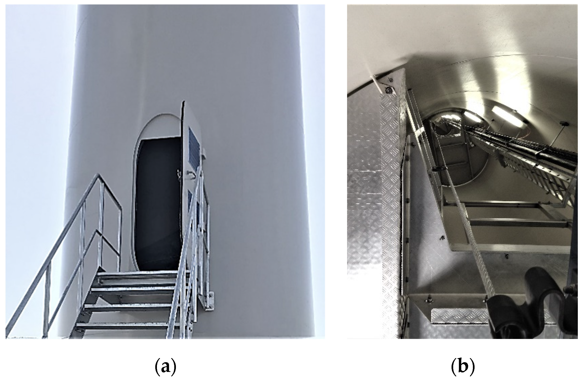
:1. Introduction
2. Current Design Standard for a Cylindrical Shell with Opening
- The ratio of tower thickness to tower radius () must not be more than 160.
- The angle () occupied by the width of the shell opening must be 60° or less.
- The ratio of opening width to opening height () must be three or less.
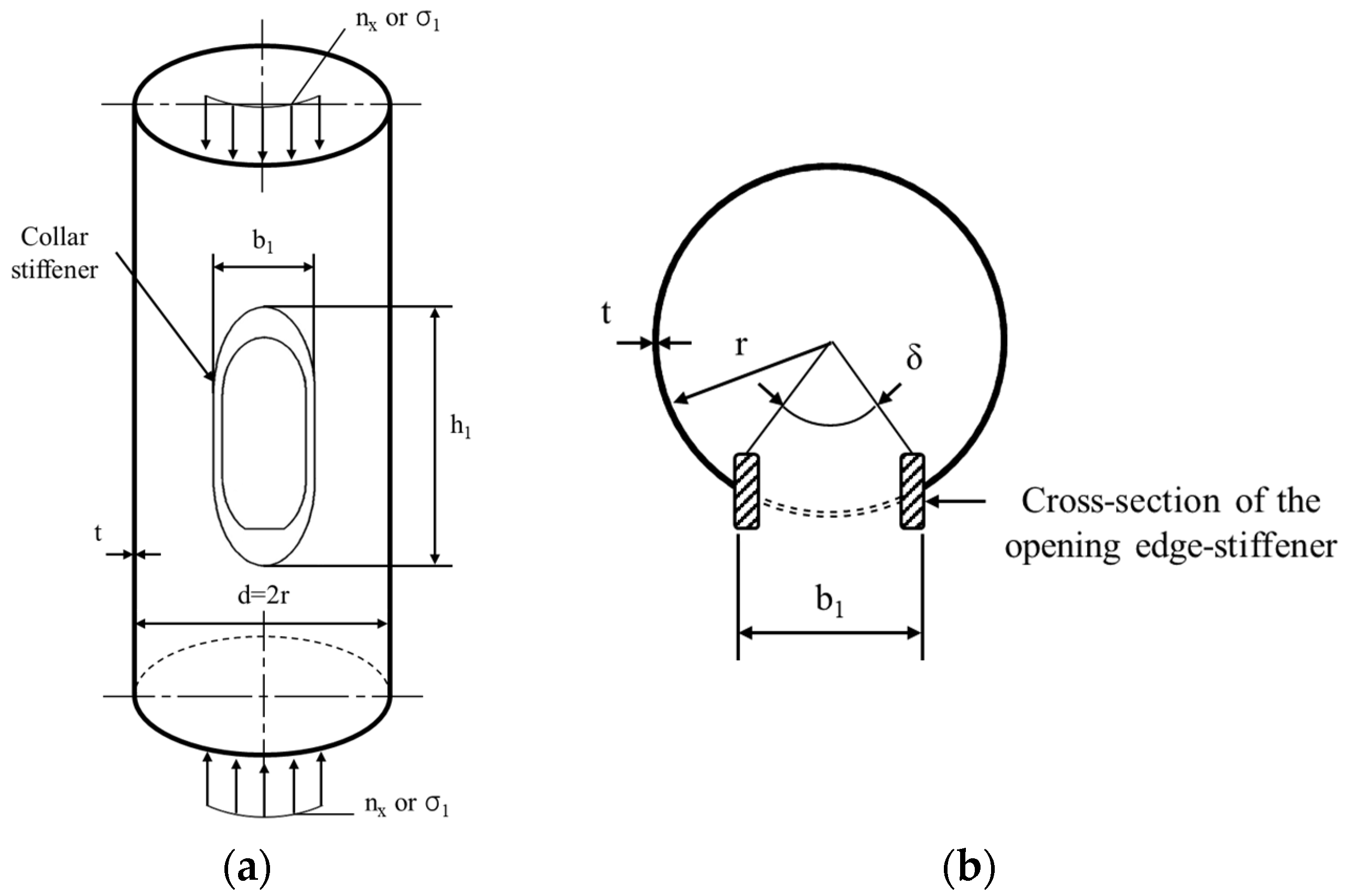
- A stiffener of specific cross-section should be installed on the centerline of the center surface of the wall.
- The cross-sectional area of the reinforcement to be installed must be at least 1/3 of the area of the wall lost due to the installation of the opening.
- The cross-section of the stiffener must satisfy the limit value () of the EN1993-1-1 standard [27].
3. Analysis Method for Investigating the Structural Stability and Ultimate Behavior of a Cylindrical Shell with Opening
3.1. Material Property
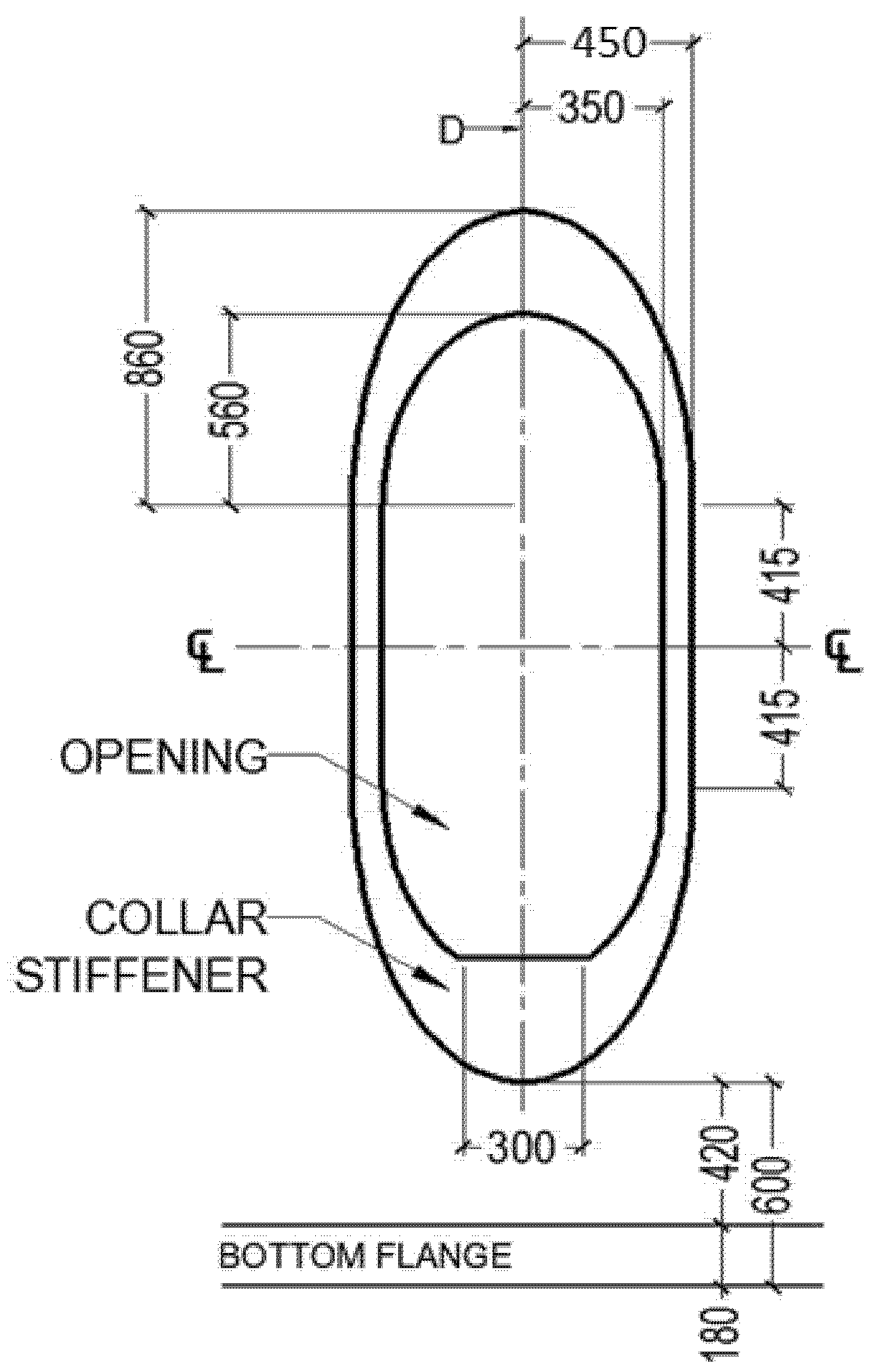
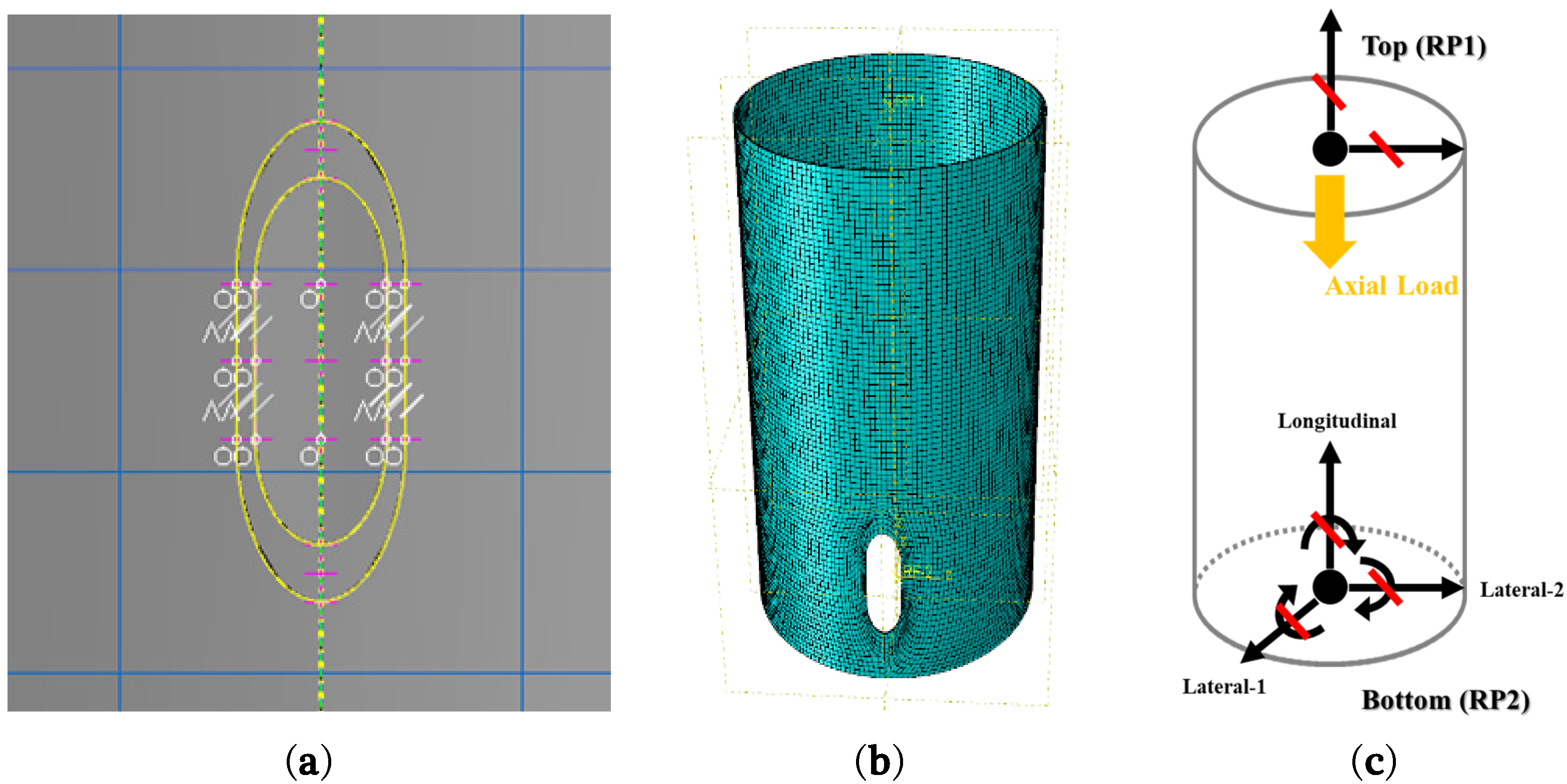
3.2. Parametric Modeling
4. Discussion: Analytical Investigation of the Structural Behavior and Proposed Equation for Collar Stiffener Thickness Design
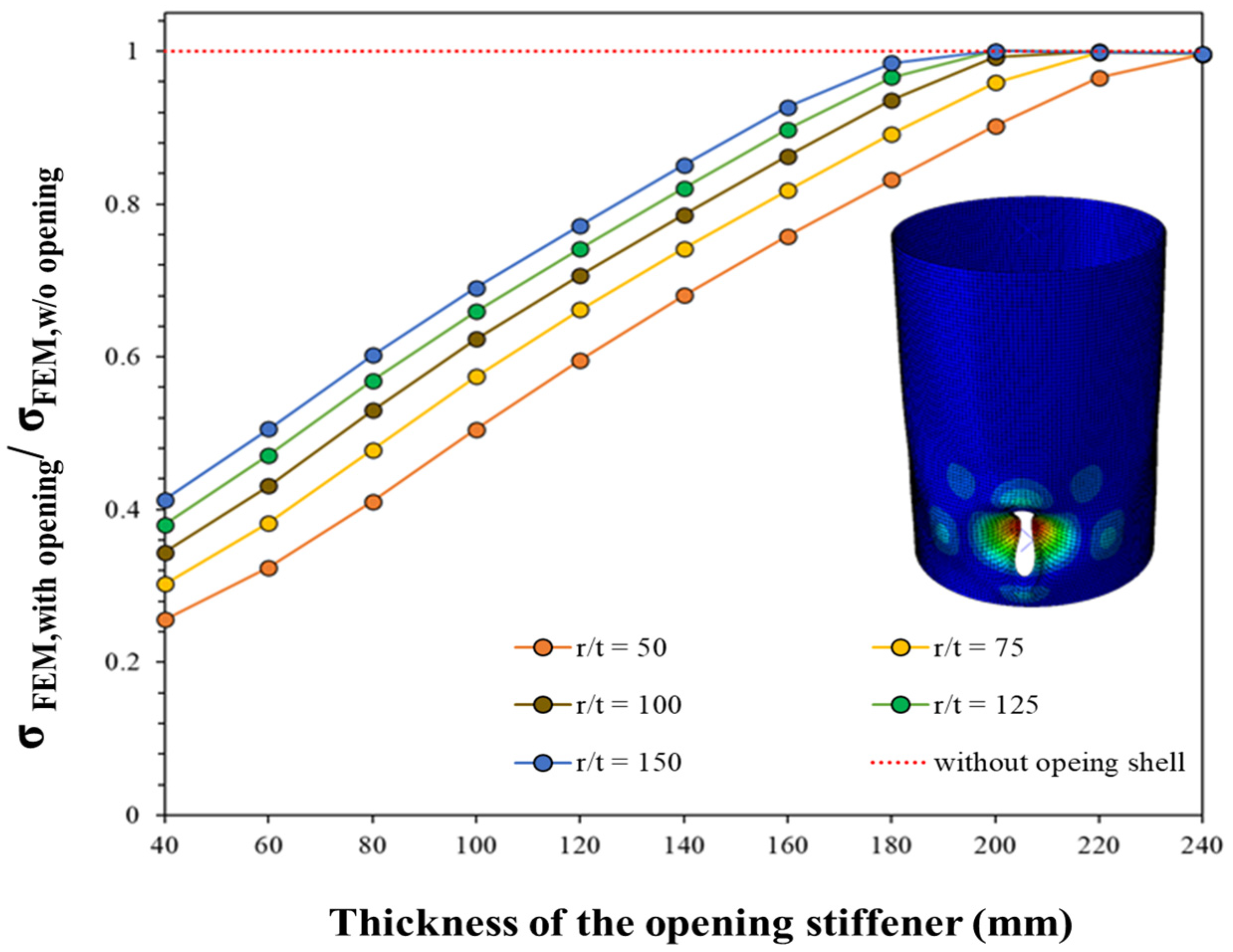
4.1. The Effects of a Collar Stiffener around the Opening on the Elastic Buckling Strength of a Cylindrical Shell with Opening
- (1)
- When = 40 mm (t = 40 mm, unstiffened opening), the effect of the opening on the elastic buckling strength was smaller as r/t increased.
- (2)
- If the thickness of the collar stiffener continuously increased at all ratios, it approached the elastic buckling strength of a cylindrical shell with no cross-sectional loss over a certain thickness.
- (3)
- At all ratios, the reinforcement effect based on the thickness of the collar stiffener exhibited a similar slope.
4.2. Ultimate Behavior of the Stiffened Cylindrical Shells with Opening Investigated Using Geometric and Material Nonlinear Analysis
- (1)
- The larger the ratio, the greater the reinforcement effect based on the thickness of the stiffener, but when = 180 mm, the design strength for all ratios converges to one point.
- (2)
- Comparing the analysis results with the design strength () applied with a strength reduction factor based on , the larger the ratio, the smaller the required design thickness of the stiffener. In other words, the effect of section loss due to the installation of openings is reduced.
- (3)
- To optimize the design of the collar stiffener for large-diameter cylindrical shells accounting for the opening, the reinforcement thickness should be applied differently based on the ratio.
4.3. Proposed Equation for Collar Stiffener Thickness Design
5. Conclusions
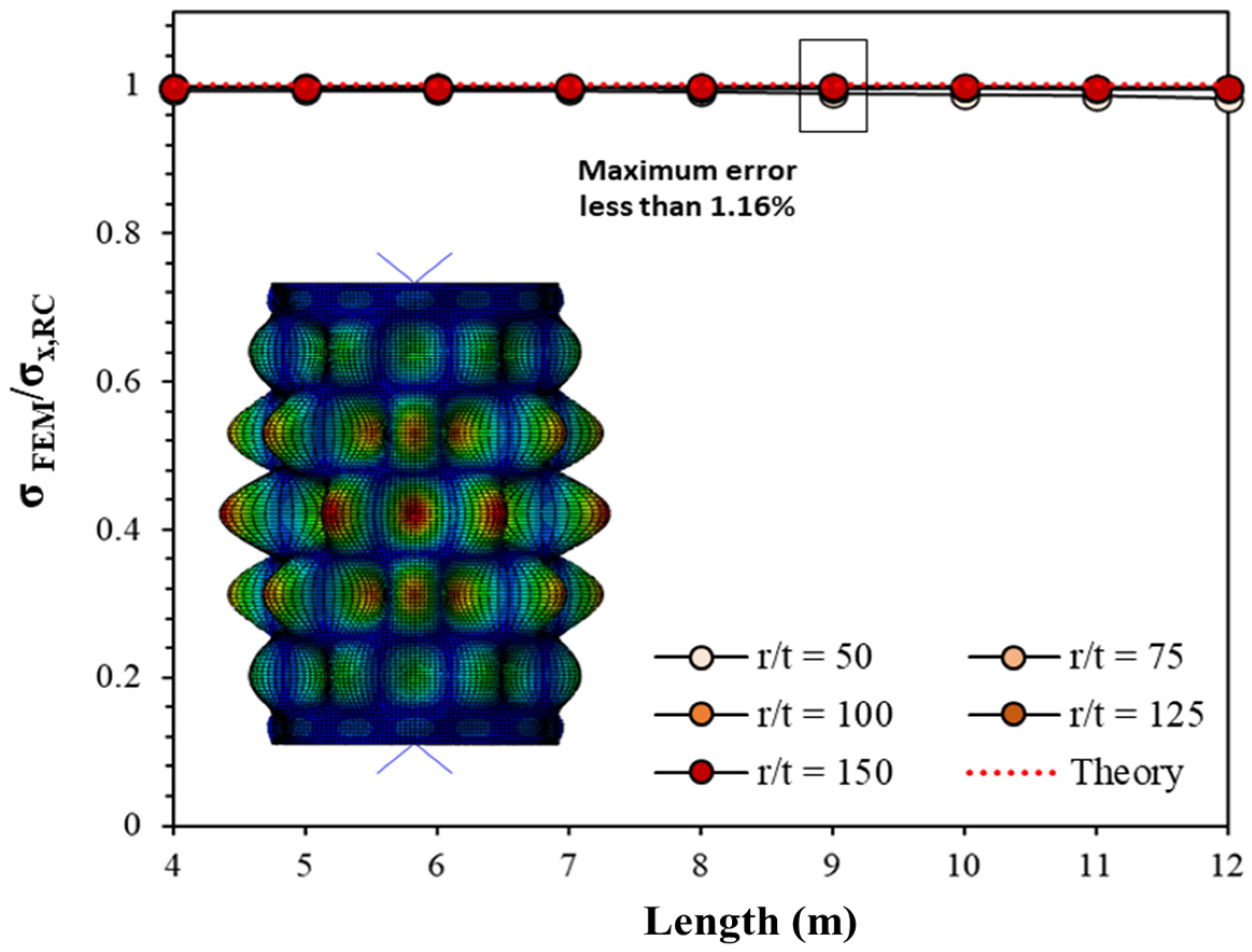
- The eigenvalue analysis results of a cylindrical shell were compared with the elastic strength provided by the theory and design standards, and a parametric model with a maximum error of 1.16% was established.
- As a result of the LBA of a cylindrical shell considering the opening, the effect on the elastic buckling strength by the opening was small as increased. In the variable model for all ratios, the elastic buckling strength of the cylindrical shell converged to a certain thickness as the collar stiffener thickness increased.
- As a result of the GMNA of the cylindrical shell considering the opening, the effect of reinforcing the collar stiffener increased as increased, tending to converge when the thickness reached 180 mm. Comparing the analysis results with the design buckling strength to which the strength reduction factor was applied, the larger the ratio, the smaller the required design thickness of the stiffener, indicating that the cross-sectional loss effect due to the opening being installed in a large-diameter cylindrical shell was reduced.
- The design could thus be optimized by reducing the thickness of the collar stiffener based on the ratio when the opening installation angle was 20° or less. A formula for calculating the minimum collar stiffener thickness was proposed using the finite element analysis results and regression analysis of the design buckling strength.
- The proposed collar stiffener thickness calculation formula could only be used within the limits of the design standard. Therefore, if a follow-up experimental study considers the defects caused by fabrication imperfections (Q, Class A, B, C) and the cylindrical shell strength is verified and supplemented, the proposed formula could be applied to various designs of cylindrical shell structures with openings.
- In this study, the structural behaviors of the large-diameter cylindrical shell with stiffened opening subjected to the uniformly applied compressive force were investigated. However, the non-uniformed compressive force could be applied to the section of the wind turbine tower due to the characteristics of the structures and various loading conditions. Therefore, further study of the investigation of the structural behaviors of the cylindrical shell with an opening under the non-uniformly applied forces should be carried out.
Author Contributions
Funding
Institutional Review Board Statement
Informed Consent Statement
Data Availability Statement
Acknowledgments
Conflicts of Interest
References
- Mehmanparast, A.; Lotfian, S.; Vipin, S.P. A Review of Challenges and Opportunities Associated with Bolted Flange Connections in the Offshore Wind Industry. Metals 2020, 10, 732. [Google Scholar] [CrossRef]
- POWER TECHNOLOGY. “Horns Rev Offshore Wind Farm, Denmark” Projects. Available online: https://www.power-technology.com/projects/hornsreefwind/ (accessed on 14 July 2021).
- Domenico, L. Dynamics of Offshore Wind Turbines. Master’s Thesis, University of Bristol, Bristol, UK, 2010. [Google Scholar]
- Sørensen, J.D. Structural Reliability Aspects in Design of Wind Turbines; The Rackwitz Symposium Technical University: Munich, Germany, 24 November 2006. [Google Scholar]
- Zhao, Z.; Li, X.; Wang, W.; Shi, W. Analysis of Dynamic Characteristics of an Ultra-Large Semi-Submersible Floating Wind Turbine. J. Mar. Sci. Eng. 2019, 7, 169. [Google Scholar] [CrossRef] [Green Version]
- Desmond, C.; Murphy, J.; Blonk, L.; Haans, W. Description of an 8 MW reference wind turbine. J. Phys. Conf. Ser. 2016, 753, 092013. [Google Scholar] [CrossRef] [Green Version]
- NREL Transforming ENERGY. New Reference Turbine Gives Offshore Wind an Upward Draft; NREL: Golden, CO, USA, 2020.
- Guz, A.N.; Chernyshenko, I.S.; Shnerenko, K.I. Stress Concentration Near Openings in Composite Shells. Int. Appl. Mech. 2001, 37, 139–181. [Google Scholar] [CrossRef]
- Zirka, A.I.; Chernopiskii, D.I. Stress Concentration in an Axially Compressed Cylindrical Shell of Medium Thickness with an Elliptic Opening. Int. Appl. Mech. 2003, 39, 1335–1338. [Google Scholar] [CrossRef]
- Golling, S. Stress Concentration at the Door Opening of Steel Towers for Wind Turbine. Master’s Thesis, Lulea University of Technology, Luleå, Sweden, 2009. [Google Scholar]
- Reyno, H.; Park, J.; Kang, S.; Kang, Y.A. Numerical Analysis for Stress Concentration of Openings in Offshore Tubular Steel Tower under Design Loading Condition. J. Korea Acad. Ind. Coop. Soc. 2015, 16, 1516–1523. [Google Scholar]
- Tennyson, R. The effects of unreinforced circular cutouts on the buckling of circular cylindrical shells under axial compression. J. Eng. Ind. 1968, 90, 541–546. [Google Scholar] [CrossRef]
- Starnes, J. Effect of a slot on the buckling load of a cylindrical shell with a circular cutout. AAIA J. 1972, 10, 227–229. [Google Scholar] [CrossRef]
- Jullien, J.F.; Limam, A. Effects of openings of the buckling of cylindrical shells subjected to axial compression. Thin-Walled Struct. 1998, 31, 187–202. [Google Scholar] [CrossRef]
- Shariati, M.; Rokhi, M. Numerical and experimental investigations on buckling of steel cylindrical shells with elliptical cutout subject to axial compression. Thin-Walled Struct. 2008, 46, 1251–1261. [Google Scholar] [CrossRef]
- Shariati, M.; Rokhi, M. Buckling of steel cylindrical shells with an elliptical cutout. Int. J. Steel Struct. 2010, 10, 193–205. [Google Scholar] [CrossRef]
- Ghazijahani, T.G.; Jiao, H.; Holloway, D. Structural behavior of shells with different cutouts under compression: An experimental study. J. Constr. Steel Res. 2015, 105, 129–137. [Google Scholar] [CrossRef]
- Alsalah, A.; Holloway, D.; Ghazijahani, T.G. Recovery of capacity lost due to openings in cylindrical shells under compression. J. Constr. Steel Res. 2017, 137, 169–179. [Google Scholar] [CrossRef]
- Hilburger, M.W.; Starnes, J.H., Jr. Buckling behavior of compression-loaded composite cylindrical shells with reinforced cutouts. Int. J. Non-Linear Mech. 2005, 40, 1005–1021. [Google Scholar]
- Reyno, H. The ultimate strength for the lower segment of tubular steel wind tower with opening. Master’s Thesis, Sangmyung University, Seoul, South Korea, 2016. [Google Scholar]
- Cho, S.J. The Ultimate Strength of Cylindrical Steel Wind Turbine Tower with Opening. Master’s Thesis, Sangmyung University, Seoul, South Korea, 2017. [Google Scholar]
- Santos, R.; Cho, S.J.; Park, J.S. Ultimate Strength of 10 MW Wind Turbine Tower Considering Opening, Stiffener, and Initial Imperfection. Int. J. Steel Struct. 2018, 18, 1318–1324. [Google Scholar] [CrossRef]
- Timoshenko, S.; Gere, J. Theory of Elastic Stability, 2nd ed.; Dover Publications, Incorporated, McGraw-Hill: New York, NY, USA, 1963. [Google Scholar]
- BSI (British Standards Institution). Eurocode 3: Design of Steel Structures-Part 1–6: Strength and Stability of Shell Structures; BSI: London, UK, 2007. [Google Scholar]
- DNV (Det Norske Veritas). DNV-RP-C202: Buckling Strength of Shells; DNVGL: Oslo, Norway, 2017. [Google Scholar]
- DNV (Det Norske Veritas). DNVGL-ST-0126: Support Structures For Wind Turbines; DNVGL: Oslo, Norway, 2018. [Google Scholar]
- BSI (British Standards Institution). Eurocode 3: Design of Steel Structures-Part 1-1: General Rules; BSI: London, UK, 2005. [Google Scholar]
- Ahn, J.T.; Shin, D.K. Ultimate Flexural Strength of Cylindrical Steel Shell for Wind Tower. Korean Soc. Steel Constr. 2015, 27, 109–118. [Google Scholar] [CrossRef]
- BSI (British Standards Institution). Eurocode 3: Design of Steel Structures-Part 1–10: Material Toughness and Through-Thickness Properties; BSI: London, UK, 2007. [Google Scholar]
- DNV (Det Norske Veritas). DNV-RP-C208: Determination of Structural Capacity by Non-Linear FE Analysis Methods; DNVGL: Oslo, Norway, 2013. [Google Scholar]


| Condition | Factor | Type of Cylinder |
|---|---|---|
| Short | ||
| Medium | ||
| Long |
| Opening Angle | S235 | S355 | ||
|---|---|---|---|---|
| 1.00 | 0.0019 | 0.95 | 0.0021 | |
| 0.90 | 0.0019 | 0.85 | 0.0021 | |
| 0.75 | 0.0022 | 0.70 | 0.0024 | |
| Thickness (mm) | |||
|---|---|---|---|
| Elastic modulus [, MPa] | 210,000 | 210,000 | 210,000 |
| First yield stress [, MPa] | 355 | 345 | 335 |
| Second yield stress [, MPa] | 358.4 | 348.4 | 338.4 |
| Ultimate stress [, MPa] | 470 | 470 | 450 |
| First yield strain [] | 0.004 | 0.004 | 0.004 |
| Second yield strain [] | 0.02 | 0.02 | 0.02 |
| Ultimate strain [] | 0.15 | 0.15 | 0.15 |
| Top (RP1) | Bottom (RP2) | ||||
|---|---|---|---|---|---|
| Direction/ Rotation axis | Displacement | Rotation | Direction/ Rotation axis | Displacement | Rotation |
| Longitudinal | Restricted | Free | Longitudinal | Restricted | Restricted |
| Lateral-1 | Free | Free | Lateral-1 | Restricted | Restricted |
| Lateral-2 | Restricted | Free | Lateral-2 | Restricted | Restricted |
| FEM (1st Mode, MPa) | Equation (1) | Equations (2) and (3) | |||
|---|---|---|---|---|---|
(MPa) | Error (%) | (MPa) | Error (%) | ||
| 50 | 2512.36 | 2541.96 | 1.16% | 2541.00 | 1.13% |
| 75 | 1686.18 | 1694.64 | 0.50% | 1694.00 | 0.46% |
| 100 | 1266.10 | 1270.98 | 0.38% | 1270.50 | 0.35% |
| 125 | 1014.46 | 1016.78 | 0.23% | 1016.40 | 0.19% |
| 150 | 845.94 | 847.32 | 0.16% | 847.00 | 0.13% |
| Diameter (, m) | Opening Angle (, Degree) | Length (m) | Thickness (, mm) | Collar Stiffener Thickness (, mm) | Analysis Type | |
|---|---|---|---|---|---|---|
| 50 | 4 | 26 | 9 | 40 | 40~240 | LBA GMNA |
| 75 | 6 | 17 | ||||
| 100 | 8 | 12 | ||||
| 125 | 10 | 10 | ||||
| 150 | 12 | 8 |
| 50 | 70 | 100 | 125 | 150 | |||
|---|---|---|---|---|---|---|---|
| Ratio to without opening shell strength | Collar stiffener thickness (, mm) | 40 | 0.26 | 0.30 | 0.34 | 0.38 | 0.41 |
| 60 | 0.32 | 0.38 | 0.43 | 0.47 | 0.51 | ||
| 80 | 0.41 | 0.48 | 0.53 | 0.57 | 0.60 | ||
| 100 | 0.50 | 0.57 | 0.62 | 0.66 | 0.69 | ||
| 120 | 0.60 | 0.66 | 0.71 | 0.74 | 0.77 | ||
| 140 | 0.68 | 0.74 | 0.79 | 0.82 | 0.85 | ||
| 160 | 0.76 | 0.82 | 0.86 | 0.90 | 0.93 | ||
| 180 | 0.83 | 0.89 | 0.94 | 0.97 | 0.98 | ||
| 200 | 0.90 | 0.96 | 0.99 | 1.00 | 1.00 | ||
| 220 | 0.97 | 1.00 | 1.00 | 1.00 | 1.00 | ||
| 240 | 1.00 | 1.00 | 1.00 | 1.00 | 1.00 | ||
| Without opening shell stress (, MPa) | 2512.36 | 1686.18 | 1266.10 | 1014.46 | 845.94 | ||
| 50 | 70 | 100 | 125 | 150 | |||
|---|---|---|---|---|---|---|---|
| Ratio to without opening shell design strength | Collar stiffener thickness (, mm) | 40 | 0.70 | 0.67 | 0.65 | 0.63 | 0.62 |
| 60 | 0.75 | 0.74 | 0.73 | 0.71 | 0.71 | ||
| 80 | 0.81 | 0.80 | 0.79 | 0.78 | 0.78 | ||
| 100 | 0.85 | 0.85 | 0.84 | 0.83 | 0.83 | ||
| 120 | 0.88 | 0.88 | 0.87 | 0.87 | 0.87 | ||
| 140 | 0.91 | 0.91 | 0.91 | 0.89 | 0.90 | ||
| 160 | 0.93 | 0.93 | 0.92 | 0.93 | 0.93 | ||
| 180 | 0.95 | 0.95 | 0.95 | 0.94 | 0.95 | ||
| 200 | 0.97 | 0.96 | 0.96 | 0.96 | 0.96 | ||
| 220 | 0.98 | 0.97 | 0.97 | 0.96 | 0.96 | ||
| 240 | 0.98 | 0.97 | 0.96 | 0.95 | 0.95 | ||
| w/o opening | 0.98 | 0.97 | 0.96 | 0.96 | 0.95 | ||
| Without opening shell design stress (, MPa) | 280.51 | 262.86 | 247.18 | 232.73 | 219.12 | ||
Publisher’s Note: MDPI stays neutral with regard to jurisdictional claims in published maps and institutional affiliations. |
© 2021 by the authors. Licensee MDPI, Basel, Switzerland. This article is an open access article distributed under the terms and conditions of the Creative Commons Attribution (CC BY) license (https://creativecommons.org/licenses/by/4.0/).
Share and Cite
Kang, S.-Y.; Won, D.; Park, J.-S.; Kang, Y.-J.; Kim, S. Structural Behavior of Large-Diameter Cylindrical Shell with Stiffened Opening. Metals 2021, 11, 1413. https://doi.org/10.3390/met11091413
Kang S-Y, Won D, Park J-S, Kang Y-J, Kim S. Structural Behavior of Large-Diameter Cylindrical Shell with Stiffened Opening. Metals. 2021; 11(9):1413. https://doi.org/10.3390/met11091413
Chicago/Turabian StyleKang, Sung-Yong, Deokhee Won, Jong-Sup Park, Young-Jong Kang, and Seungjun Kim. 2021. "Structural Behavior of Large-Diameter Cylindrical Shell with Stiffened Opening" Metals 11, no. 9: 1413. https://doi.org/10.3390/met11091413
APA StyleKang, S.-Y., Won, D., Park, J.-S., Kang, Y.-J., & Kim, S. (2021). Structural Behavior of Large-Diameter Cylindrical Shell with Stiffened Opening. Metals, 11(9), 1413. https://doi.org/10.3390/met11091413