Article

Crystal Growth on Cenospheres from High-Calcium Fly Ash

by
Sorachon Yoriya
* and
Phattarathicha Tepsri
National Metal and Materials Technology Center, 114 Thailand Science Park, Pahonyothin Road, Khlong Nueang, Khlong Luang, Pathum Thani 12120, Thailand
*
Author to whom correspondence should be addressed.
Crystals 2021, 11(8), 919; https://doi.org/10.3390/cryst11080919
Submission received: 19 July 2021 / Revised: 30 July 2021 / Accepted: 3 August 2021 / Published: 7 August 2021

Abstract

:
This work presents a study of cenosphere separation from lignite high-calcium (~24 wt.%) fly ash by centrifugal method; this is the first report for Mae Moh, Thailand, fly ash with this high calcium content using this technique. The effect of centrifugal parameters on cenosphere yield and properties were investigated. Those properties include physical properties, morphology, chemical composition, and mineral phases. The recovery yields are in the range of 0.34–0.64%, approximately one third of the yield obtained from the general gravity settling method. Density, particle size, and morphology of the collected cenospheres appeared to be independent of sequence of the applied speeds and times. Interrelation of chemical composition and mineral phases was established, with the focus on calcium carbonate formation on cenosphere surface and crystallite size study. The study has revealed the preferential formation of calcite–(104) peak is observed–by cenospheres, with stable growth behavior of crystallite sizes obtained from all the centrifugal conditions. The result was compared to that obtained from the sink-float method for a better insight. The influence and limitation of the centrifugal method, the varied parameters, and the relevant reaction pathways on crystal growth process in terms of important dissolving species (i.e., Ca2+ and CO32−) behavior in the ash suspension were discussed.

1. Introduction

Hollow cenospheres are known as a valuable fraction of fly ash with numerous applications [1,2,3]. Cenospheres are spherical, lightweight, mechanically high strength, and chemically inert shells. True density of the light weight cenospheres normally varies in the range of 0.2–2.9 g/cm3 [4,5,6,7], with such properties thus enabling them to be widely used and a demandable additive component to many industrial products. Due to unique properties and their large availability in the world market, cenospheres are used in a number of significant applications such as construction industry and building materials [8,9,10,11,12,13], refractory [14], insulation [15], composites [16,17,18,19,20], railway [21], and alloys [16,22]. Particularly in synthesis and functionalization applications [1], it is important to know the chemical and phase compositions of cenospheres because they have considerable influence on the predictable and controlled properties of the functional materials. Cenospheres composed of different chemical constituents are known to depend on the coal used and the transformation during the combustion process, and different stages of the phase transformation of ash particles determine their molecular structure and overall chemical composition as manifesting in surface texture [23,24]. Low-calcium fly ash is traditionally produced from bituminous coal, and high-calcium fly ash is mostly from lignite coal. With their distinctly physicochemical characteristics, the differences lead to different orders of applicability and reactivity in the applications. The chemical properties of cenospheres are the matters of considerable concern in determining the favorable directions and subsequently the reaction rate. High-calcium fly ashes have a large content of small particles, possessing various types of crystalline calcium and bearing compounds that could rapidly generate hydration products when being used as the mineral admixture in concrete [25]. The high calcium hydroxide content leading to crystals formed on cenosphere surface limits their applicability in the cement industry.
Density and composition of fly ash and cenospheres play an important role in the separation process of cenospheres, influencing the separation efficiency and quality of the separated product. The lightweight cenospheres content by nature in fly ash varies depending on the type of fly ash and the process parameters, in most cases from ~0.3 to 2 wt.% [1,2,3]. Even though they are a small fraction in fly ash, efforts have been made to obtain high recovery yield of cenospheres from fly ash in the most efficient way by manipulating various separation parameters: water-based [6,23,26,27] and nonaqueous mixtures [5,28,29,30]. The results of cenosphere separation using the low-calcium fly ash have been widely reported [7,26,31]. For the high-calcium fly ash, dealing with chemistry in the solution is an interesting yet challenging topic with particular purpose to obtain good quality of cenospheres and remain high yield. The traditional method used for cenosphere separation is wet separation. The wet separation basically includes sink-float method and centrifuge method. The separation efficiency of the sink-float method is based on the gravity settling mechanism, while that of the centrifugal method is based on the angular moment velocity [32]. The achievement of these two methods is on a mutual basis of the collection of the top layer, which is the floating fraction of low-density cenospheres. Cenosphere separation by using the centrifugal method has been rarely mentioned [6,23,31,33], comparing to the sink-float method. Quantitative data on the relation of the centrifugal separation parameters and the composition-phase chemistry in aqueous system particularly for the high-calcium fly ash up to >20 wt.% CaO level has not been found; it is understandable that different power plants produced fly ash and cenospheres of various chemical compositions predominantly depend on coal type [3,34,35,36]. An elucidation study would be helpful in understanding the separation efficiency of the technique correlating with the properties of cenospheres in a comparison view of different types of cenosphere separation mechanisms. In addition, details about how calcium carbonate crystals formed on cenospheres under the centrifugal conditions, to our knowledge, has not been completely discussed. While for the sink-float method, it has been reported more on the use of high calcium fly ash as prolonged soaking time in water medium is known to result in low quality cenospheres [27,29]. In the suspension of high-calcium fly ash and water mixture, there is a degree of complexity of the process reactions determining the growth of calcium carbonate crystals on cenophere surface. The interaction between dissolving ions and crystal surfaces is essential for understanding the physical-chemical conditions in the crystal formation process; this is essential to obtain good quality cenospheres with appropriate manipulation of the separation process.
Detailed data of cenosphere separation using the general sink-float method have been extensively reported in literature, while the work in area of centrifugation, another sedimentation but with rotation applied, has been rarely mentioned. This work presents the investigation of cenospheres recovery from the high-calcium class C fly ash using centrifugal method, emphasizing the influence of the centrifugal parameters on the properties of cenospheres. In this work, the characterized properties of cenospheres are analyzed in terms of their interrelation of chemical composition, phase, and morphology of calcium carbonate, not only with focus on the crystallographic study to explain the crystal formation in aqueous system, but also comparing types of separation between the centrifugal and sink-float method. That is, we particularly present the crystallographic plane identification and explanation into chemistry (i.e., dissolving ions, reaction steps) for understanding the calcium carbonate crystal formation and its preferential growth behaviors under the centrifugal method, to provide a comparison to the sink-float method for better insight.

2. Materials and Methods

2.1. Cenospheres Separation

High calcium class C fly ash was obtained from Mae Moh thermal power plant, Thailand. Mae Moh power plant uses lignite coal in the combustion process for electricity production. The apparent density of fly ash was 2.48 g/cc and the bulk density was 1.3 g/cc. The average size, D [4,3], of fly ash was 41.51 μm, with a wide range of particle size distribution: <1–10 μm (40.79 wt.%), 11–50 μm (33.08 wt.%), 51–100 μm (14.33 wt.%), 101–250 μm (10.89 wt.%), and 250–500 μm (0.91 wt.%).
The fly ash was oven-dried at 105 °C for 48 h prior to cenospheres separation. The separation of cenospheres was performed through the centrifugal method using water as the medium. The fly ash sample was incorporated into water in the centrifugal tube at 1:10 (g/mL) fly ash–water ratio, at this stage giving a gentle stirring to help them mix thoroughly. Total volume of the centrifugal tube was 500 mL. The centrifugal speed was set at 1000, 2000, 3000, and 4000 rpm. The centrifugal time was fixed at 10 and 30 min for all prepared conditions; three measurements were performed. After centrifuging for a given period at a fixed speed, the supernatant liquid was carefully poured (about 1/3 of the liquid height) and filtered by suction filtration to separate the floating part of cenospheres from the sediment part of fly ash at the bottom of the centrifugal tube. In this study, the sink-float method was also performed for a comparison study. A 1:10 fly ash-to-water ratio mixture was also prepared, then stirred for 5 min before leaving to sediment for 30 min and skimming off the floating layer. pH of all the centrifugal fractions was measured. In this study, the experiment was set for the sink-float in comparison to the centrifugal method. The fly ash-medium mixtures were prepared by varying fly ash contents as follows: 1.25, 2.5, 5, 10, and 20 wt.%, which led to varied fly ash-water ratio of 1:80, 1:40, 1:20, 1:10, and 1:5, respectively. The mixtures were stirred for 5 min before leaving for 30 min to sedimentation. The cenospheres were collected by skimming off the surface after 48-h soaking. The recovered cenospheres from both methods were dried in the oven at 105 °C for 48 h. The cenospheres recovery yield was calculated by determining a ratio of the weight of floating cenospheres to the weight of total fly ash, then multiplying 100 to make it a percent recovery value. The average percentage yields and the standard deviation were determined and plotted against the varied parameters.

2.2. Material Characterization

Characterization of the collected cenospheres was carried out by examining density, particle size, chemical composition, and phase study, and compared with the fly ash. In this study, apparent density was investigated by ultrapycnometer (Ultrapycnometer 1200e, Quantachrome Instruments, Boynton Beach, FL, USA). Particle size and distribution of the samples were determined by laser particle size analyzer using dry dispersion units (Masterizer 2000, Malvern Instrument, Malvern, UK); the resulting average particle size was obtained by means of the volume mean diameter (D [4,3]). Morphological structures of both fly ash and cenospheres was studied by scanning electron microscopy (SEM) (Phenom ProX, Eindhoven, the Netherlands). In addition, the precipitates of interest on cenosphere particle were elementally analyzed by energy-dispersive spectroscopy (EDX) to particularly determine the compositional data of those sizes and shapes depositing on the cenosphere surface. Chemical composition of the bulk samples was carried out using energy dispersive X-ray fluorescence (EDXRF; EDAX Smart Insight, ORBIS PC, Jersey City, NJ, USA); the results were presented as the average value and obtained from three experimental measurements. Mineral phases of the samples were characterized by X-ray diffraction (PANalytical B.V., Almelo, the Netherlands) using a PANalytical XPert PRO diffractometer (Cu Kα radiation (1.540 Å), with a scan range of 2θ = 10–80° and a scan step of 0.5 s. Phase identification was done by MDI Jade software (Materials Data, Inc., Livermore, CA, USA). After phase identifying, the crystallite sizes were estimated from the line broadening of the (104) peak of calcite phase. The crystallite size (D) was calculated from Scherrer equation [37]:
D = 0.9λ/FWHM cosθ
where 0.9 is Scherrer’s constant, λ is wavelength of the Cu Kα radiation (1.540 Å), FWHM is the corrected full width at half-maximum intensity of the target peak, and θ is Bragg reflection angle.

3. Results

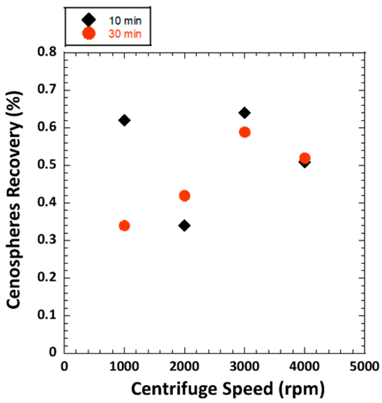
3.1. Cenospheres Recovery by Centrifugal Method
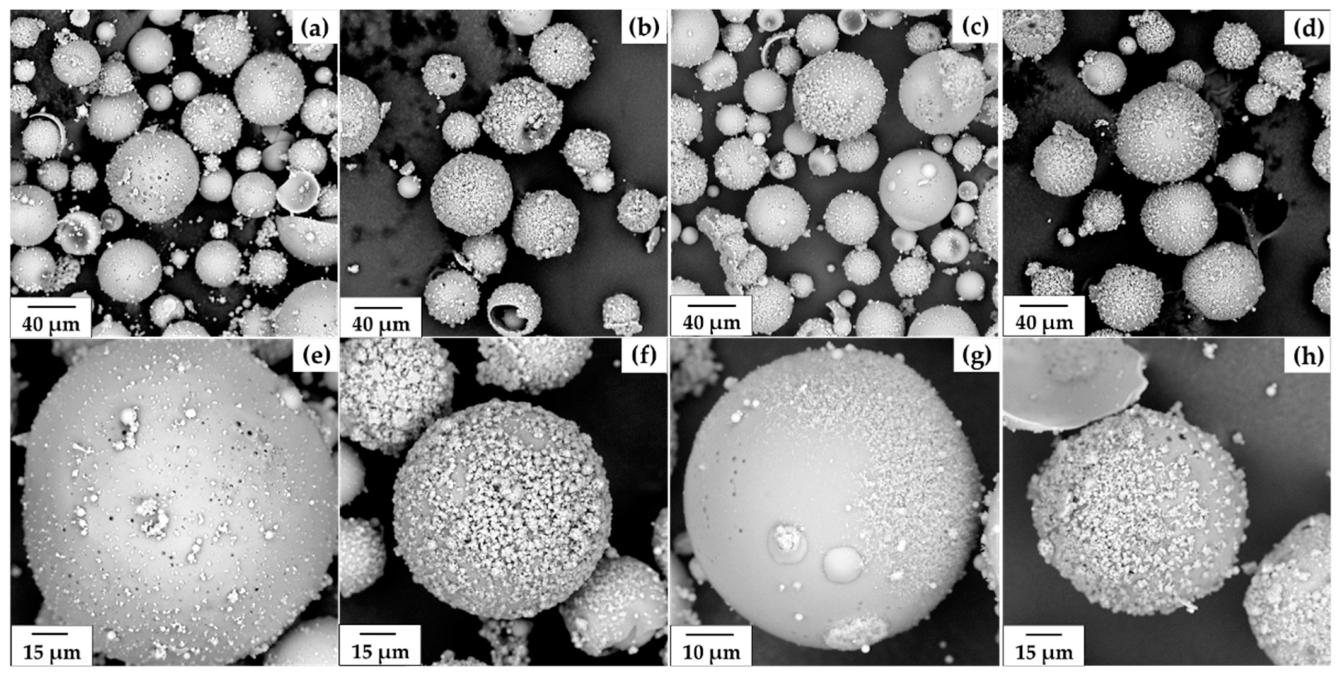
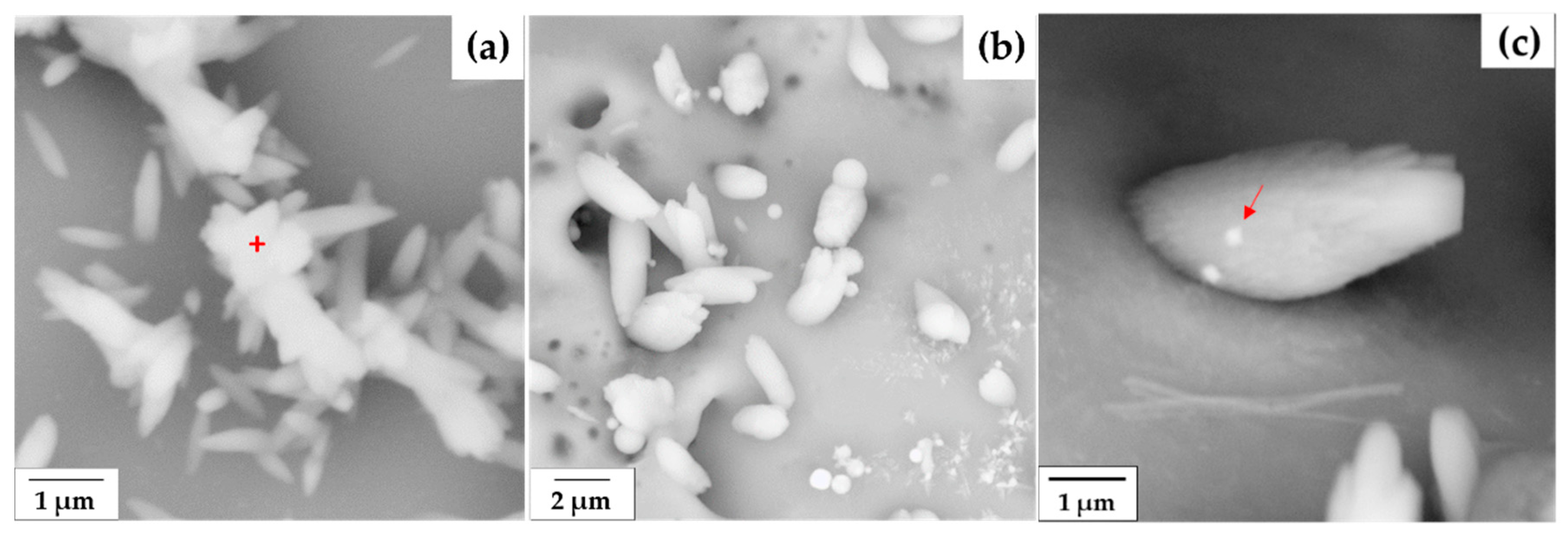
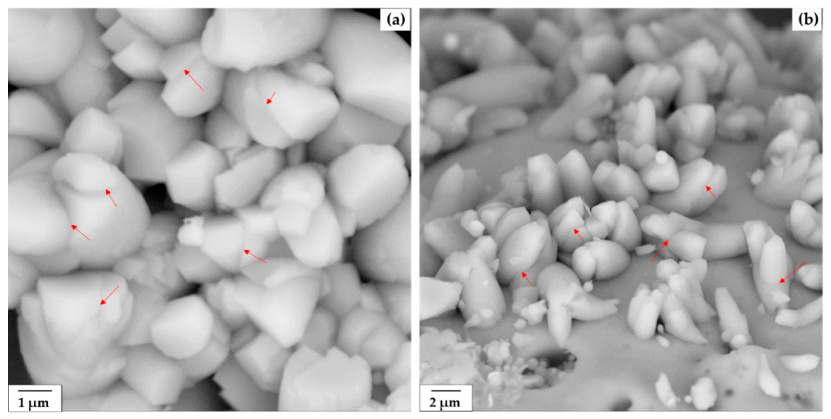
The cenospheres recovery yield of all portions of the centrifugation was calculated and is shown in Figure 1. The trend of percentage yields seemed to show an ambiguous correlation between the centrifugal time and speed. The recovery yields of all samples are closely in the range of 0.34–0.64%. The quantitative yields obtained from the centrifugal method were found to be limited; in the fraction ratio, about one third of the yield was obtained from the sink-float method. The cenospheres yield obtained from the sink-float method by using the same specification of fly ash and the fly ash-medium ratio of 1:10 was ~1.5% [27]. The result obtained in this study is similar to the achievement found for the use of high-calcium fly ash with 33 wt.% CaO; the recovery yield was 0.5% for the collected cenospheres of density <1.6 g/cm3 [23].
Multiple measurements yielded the density and relating average particle size precisely in the narrow ranges of 0.9–1.0 g/cm3 and 43–55 µm, respectively. With the short period of centrifugal times (10 and 30 min), all samples appeared to have similar distribution profiles of particle size, with no significant difference in the particle size distribution of the collected cenospheres. The particle size distribution profiles of the cenosphere fractions obtained from the centrifugal method showed the typical asymmetric particle size distribution—nearly normal Gaussian type, which is similar to those obtained from the sink-float method using water-acetone as a medium, 1:10 fly ash-to-medium ratio [29]. The majority (>90 wt.%) of cenosphere particles ranged in size from ~45 to 250 µm. For the bulk cenospheres collected from Mae Moh lignite fly ash, the typical fraction ratio of the heavier cenosphere particles (density > 1.2 g/cm3) to the lighter particles (density < 0.8 g/cm3) is 1.11, a typical characteristic of cenospheres [27]. The density and particle size values of the cenospheres collected from those varied conditions in Figure 1 were found seemingly independent of the centrifugal parameters. In the method used in this study, there could possibly be degrees of complexity and some uncertainty involving the separation process and determining the cenosphere yield, thus affecting the obtained density and particle size. The detail is described in Section 4.

3.2. Morphology

The color of the collected cenosheres from all samples looked similar, brownish grey. Note that variation of the color to the lighter color indicates the presence of more calcium oxide content, while the darker color was estimated to contain high organic content [38]. The SEM images of cenospheres obtained from 10-min centrifugation at different centrifugal speeds are presented in Figure 2a–h. No distinguishing difference could be observed on the SEM images of cenospheres obtained from the 30-min condition. The cenospheres obtained from the centrifuge method are spherical, irregular in sizes and shapes, smooth and dense, and perforated. The broken particles confirmed the hollow structure as typically characteristic of cenospheres. Mostly observed for Mae Moh cenospheres, the smaller size (<100 µm) preferred the single-ring structure, while the larger size (>100 µm) with thicker shell has porous walls [27]. It is assumed that the surface of cenospheres has an unclean appearance due to being covered in small precipitates (Figure 2a–h) as normally observed for the sink-float method for short periods of ash soaking. Further, the surface appeared to show the thorn-like microstructure (~1–3 µm in size) forming clusters on the particle surface; Figure 3a. This occurrence is similar, but relatively smaller in size, to that observed previously for the sink-float method [27]. The elemental analysis by high-magnification EDX has shown that this thorn-like structure (the marked position in Figure 3a) is calcium enrichment, mainly containing Ca (41.0 wt.%), C (25.3 wt.%), and O (33.8 wt.%). It could be possible that some amorphous phase of calcium compound was formed at the initial stages within minutes. Small structures typically appeared with size less than 1 µm, and then transformed into crystalline calcite as the reaction progressed via coupled dissolution/precipitation governed by mass transport [39]. The calcium carbonate formation occurred within a short-time period of centrifugation and herein is attributed to the acceleration effect due to the rotation of centrifuge that facilitates velocity of the moving particles and thus the consequent calcium carbonate growth reactions and rates [40]. Further, an interesting behavior noticeably observed during the growth of calcium carbonate crystals is that the crystal seemed to take away the iron particles from the ash surface where they were originally located; see the small dots of iron particles on the side of the crystal in Figure 3c. This iron structure was normally observed on the iron-rich cenospheres containing Fe2O3 content of ~7–12 wt.% [27].

3.3. Chemical Composition

Table 1 shows the chemical composition of cenospheres obtained from different centrifugal speeds and times characterized by X-ray fluorescence (XRF). The histogram plots of SiO2, Al2O3, Fe2O3, and CaO are illustrated in Figure 4a,b to provide the overall view of these four majorities of cenospheres obtained from each fraction. The major components in the cenospheres are SiO2 and Al2O3; ~28–46 and ~12–22 wt.%, respectively. The cenospheres contain these four major compositions in a range of 92.65–94.85 wt.%, indicating their siliceous-alumino characteristic, with the values approximately in close range of those found for the sink-float method (several hours of separation) [27] and reported for cenospheres from different countries [23,38,41,42].
Figure 5a shows the plots between silica and alumina for both the 10- and 30-min conditions; the curves are related by the general linear regression equation: SiO2 = 4.46 + 1.94 [Al2O3] and y = 1.60 + 2.06 [Al2O3], respectively. The same siliceous-alumino characteristic relation of magnetic-typed cenospheres of narrow fractions was reported by Fomenko et al.; SiO2 = 3.1 + 3.2 [Al2O3] [41]. The values from the 10-min condition lie in the higher regime compared to those from the 30-min condition, demonstrating the more silica and alumina contents in the collected cenospheres prone to containing larger particles in the fractions [27]. The SiO2-Al2O3 relation values in the lower range for the 30-min condition were also a result of a greater contribution of more calcium oxide in the fraction, agreeing well with the trend seen in Figure 4b. In spite of such significant differences in the major SiO2-Al2O3 composition, the obtained morphology of cenospheres from different centrifugal speeds (Figure 2) appeared to be similar. It is apparent from this finding that the centrifugal time did not show its great effect on the morphology appearance, but did on the finer scale of major siliceous-alumino composition, as the effect of the post-formed calcium carbonate crystals became more pronounced with time on the cenosphere surface, hence reflecting such a significant difference in the chemical composition.
The SiO2/Al2O3 ratio of the cenospheres to confirm the majority constituents was determined. Figure 5b presents the SiO2/Al2O3 ratio of cenospheres collected from different centrifugal speeds and times. The average SiO2/Al2O3 ratios for the fixed centrifugal times at 10 min and 30 min were in the very close range; 2.17 ± 0.02 and 2.16 ± 0.02, respectively. Comparing to those of the sink-float method using the same source of fly ash from the same power plant [27], the average SiO2/Al2O3 ratios were found in a narrow range of 2.1–2.2 (water medium) and 2.21 (water-acetone mixtures) for the cenosphere size range of <45–250 µm [27]. These values clearly confirmed the same chemistry of cenospheres that originated from the same parent coal and the combustion conditions, but independent of the type of cenosphere separation and the medium solution. Those combustion conditions are such as furnace temperature, residence time, and cooling rate [1,3]. Oxide of Si and Al are typically dominant in cenospheres with the SiO2/Al2O3 ratio possibly varying from 1.3 to 2.5 in accordance with the mineralogical phases of cenospheres [43].
The samples contained relatively lower composition fractions of Fe2O3 and CaO; ~7–9.6, and 18–45 wt.%, respectively. The centrifugation did not alter the composition of Fe2O3 significantly, but seemingly did for the CaO; the 30-min centrifugation showed its effect on a slightly increased content of CaO with respect to the 10-min centrifugation. The typical Fe2O3 content in Mae Moh cenospheres obtained in recent years was found in the range of ~7–13 wt.% [27,29]. The increase in Fe2O3 content of 4–21 wt.%. could have led to the increased content of the spotty, nonuniform surface of cenospheres [38]. In the magnetic sphere fraction of fly ash, Fe could possibly present in different forms of iron-bearing species; i.e., magnetite with admixtures of Mg, Mn, and Ca; hematite (α-Fe2O3; 5–17 wt.%); maghemite (γ-Fe2O3); and iron-bearing glass in a paramagnetic phase [44].

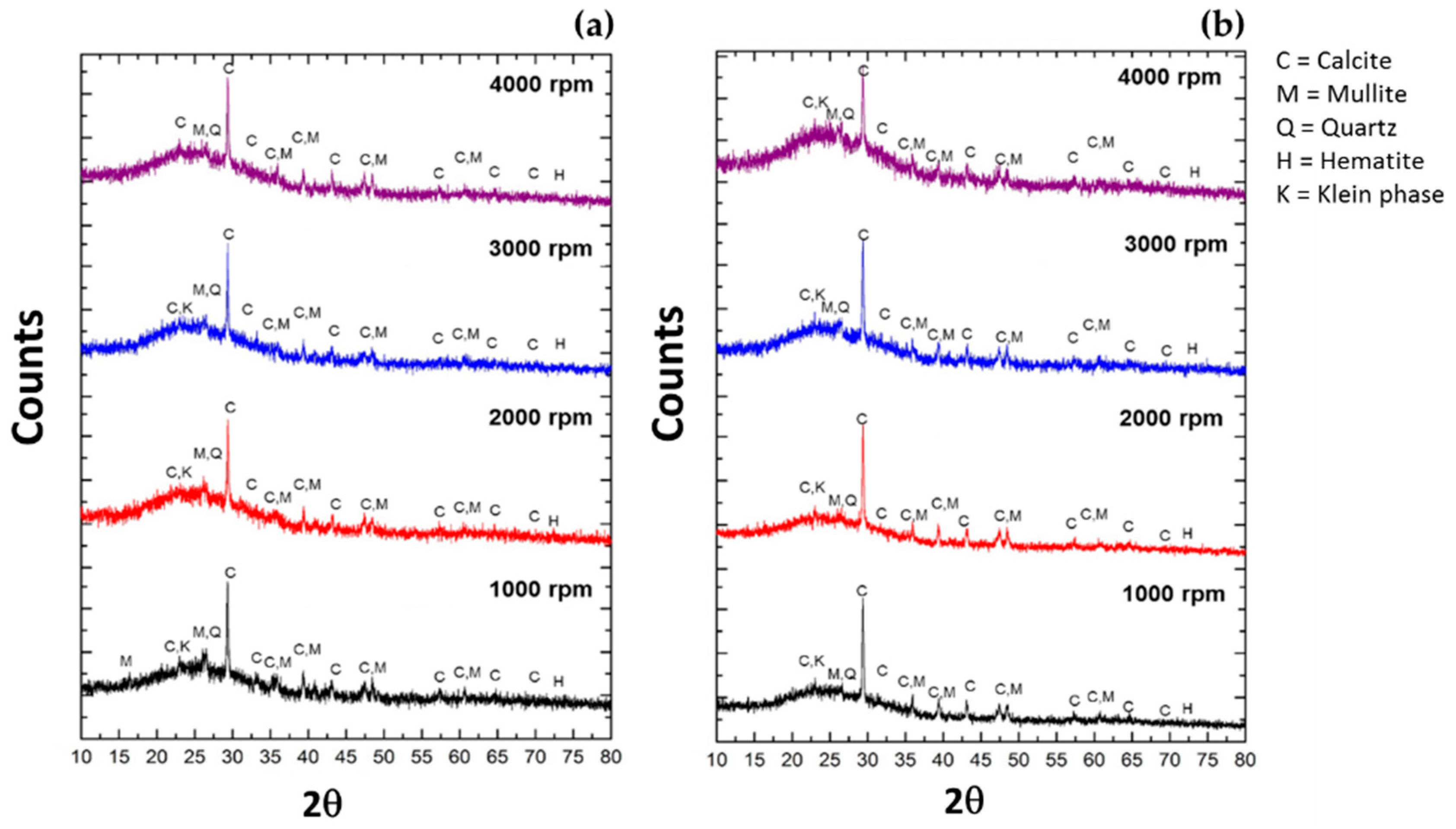
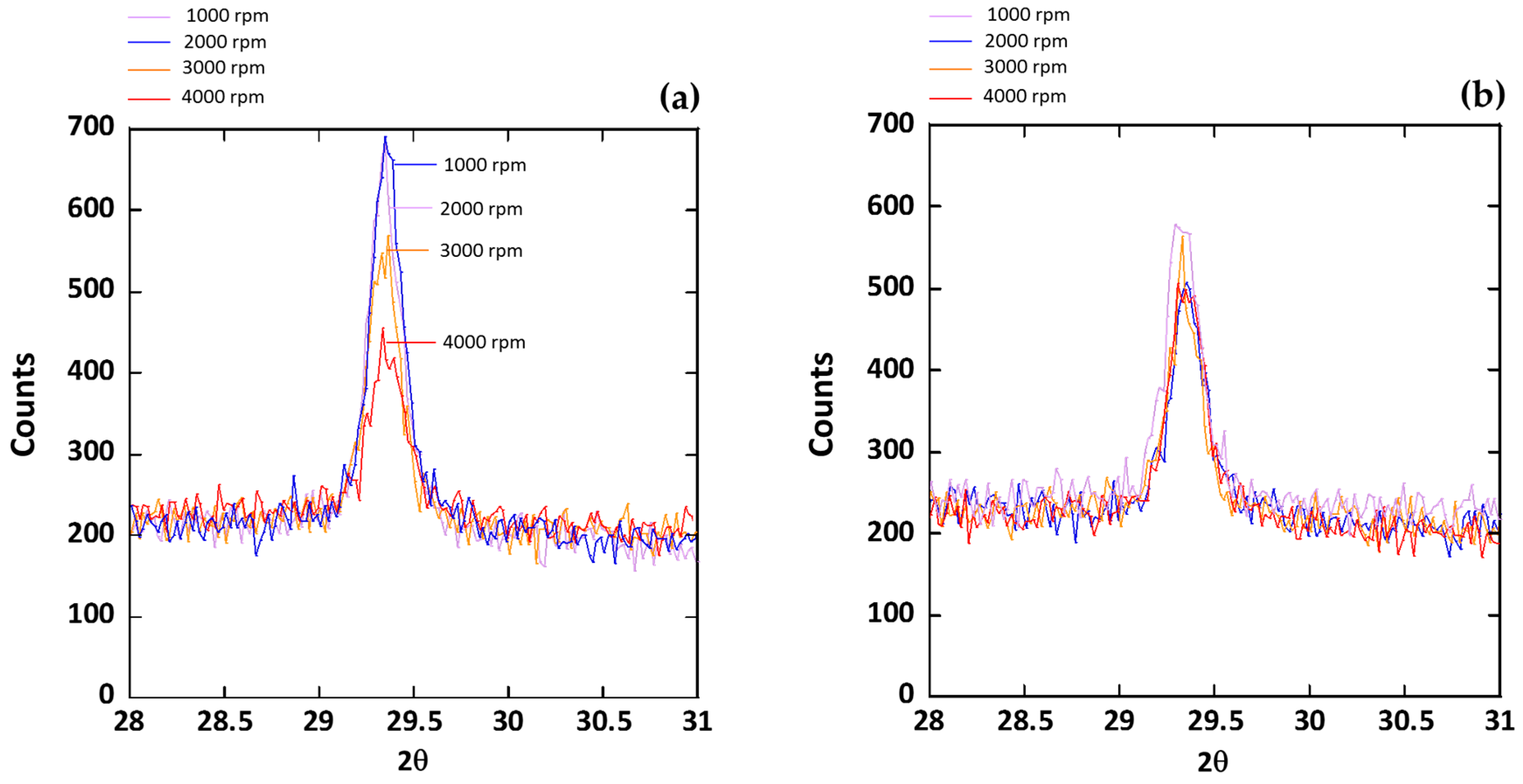
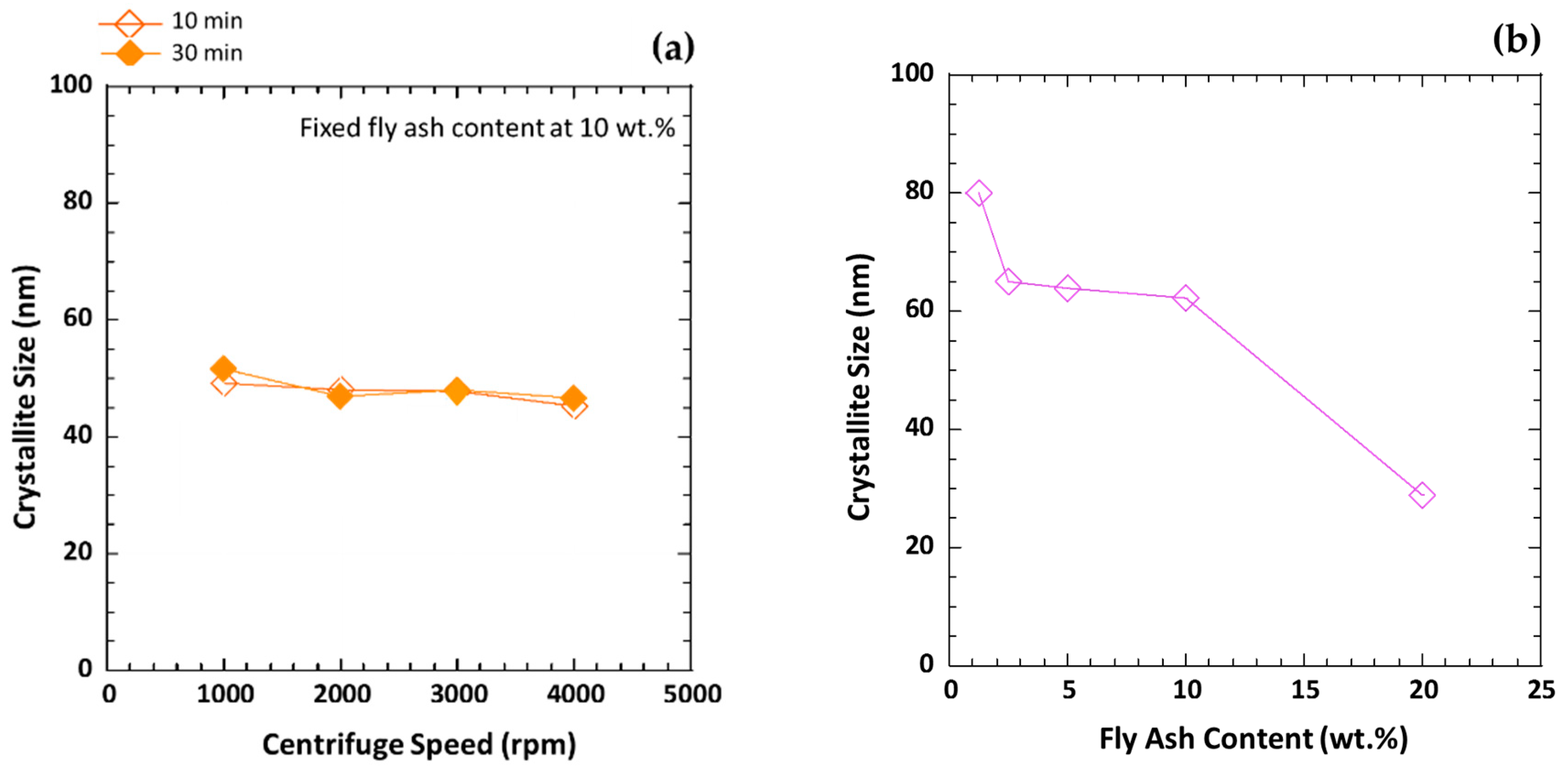
3.4. Minerallogical Phase Study

The phase composition of fly ash used in this study includes anhydrite (CaSO4), mullite (3Al2O3·2SiO2), quartz (SiO2), Lime (CaO), magnetite (Fe3O4), potassium magnesium silicate (K2MgSi5O12), portlandite (Ca(OH)2), merwinite (Ca3Mg(SiO4)2), and srebrodolskite Ca2((Fe1.559Al0.441)O5) [27]. The bulk cenospheres obtained from different centrifugal conditions were subject to mineralogical study to investigate their phase compositions. Figure 6a,b shows the XRD patterns of cenospheres containing both amorphous (hump) and crystalline (distinct peak) characteristics. The broad elevation forming a hump seen for all cenosphere samples, indicating the characteristic of glass diffraction maxima, is in the 2θ range between 17 and 35°, being centered roughly at 26°. The different position of the hump, being centered at lower or higher angle, may reflect a significant difference in the glass structure in the low- or high-calcium ash spheres, respectively [45]. In the high-calcium fly ash, there it was evident that the glass structure within the siliceous type was progressively modified by the greater calcium content. The crystalline mineral phases were identified as follows: calcite (CaCO3), mullite (3Al2O3·2SiO2), quartz (SiO2), hematite (Fe2O3), and klein phases (calcium, aluminum, sulfur bearing minerals), which are preferably soluble species in high-calcium fly ash [46].
In Figure 6, the high intensity peaks of calcite (104) appearing at 2θ = 29.40° for all samples are obviously observed. The lattice parameters of calcite (104) are as follows: a = 4.9887 Å, b = 4.9887 Å, and c = 17.0529 Å (hexagonal). In addition, the peaks with lower intensity were obtained such as the (110) plane (2θ = 35.795°) and the (116) plane (2θ = 48.519°); the growth on different planes depended on the formation energy and the thermodynamic stability of the calcium carbonate nucleation in the solution. The sharp peak generally is a result from homogeneities in chemical composition and extremely fine crystallite size [47]. As seen in Figure 7, intensity of the (104) peak decreased with the increased centrifugal speeds for the 10 min centrifugation, but seemingly no change was observed for the 30 min. The crystallite sizes of the collected cenospheres from the centrifugal method, calculated from the Scherrer formula, are shown in Figure 8a. This is despite the obvious trend with the increased centrifugal speeds where a significant decrease in the peak intensity was obtained. The CaCO3 (104) crystallite sizes of for all samples seemed to be in the approximate range, ~47–49 nm (avg. 47.99 nm), almost unaffected by the applied centrifugal speeds in such short periods of centrifugation.
Variation of calcite crystallite size with process parameters was found in another system. In the sink-float system without the centrifugation effect, using the same fly ash-to-medium ratio (1:10) but prolonged soaking time (48 h) resulted in the average CaCO3 (104) crystallite size of 62.2 nm, which is 29.6% larger in size compared to that of the centrifugal method. Nonetheless, this finding revealed that the growth of CaCO3 on cenosphere particles was on the same specific growth sites, calcite (104) surface. A further attempt was made to consider the effect of fly ash concentration on calcite crystallite size by varying fly ash content in water; see the result in Figure 8b as variation of CaCO3 crystallite size was obtained between ~25 to 80 nm. The crystallite size tended to decrease from ~80 nm, then drastically from ~65 nm to ~30 nm, with the increased fly ash content from 10% to 20%, respectively.

4. Discussion

In sedimentation centrifuge, the centrifugal force is used with a purpose to separate solids from liquids. On the basis of centrifugation, the rate of separation by gravitational force mainly depends on the particle size and density; the particles of higher density typically travel at a faster rate and will be separated from the lighter less dense. Considering the relationship governing ideal sedimentation, the velocity of sedimentation (ν) of a small spherical particle is dependent upon its radius (r) and density (σp) in a liquid medium of density (σm) and viscosity (η) under the influence of a centrifugal force [32].
ν   =   2 r 2 σ p     σ m ω 2 x 9 η
where ω is angular velocity, and x is the distance of the particle from the center of rotation. This relationship can only be valid if the particle is spherical shape, the motion of the particle is uniform, and the particle is unhampered (moving freely) by neighboring particles. In the present case, this correlation could not exactly apply to both fly ash and cenospheres of broad particle size distributions and densities, especially with the hollow cenospheric characteristically large size but light weight. The ash particles are spherical but rather irregular in shape; to some extent, vesicular spheres with small and agglomerated particles attached, forming a somewhat non-spherical shape [48]. Additionally, the ash surface is perforated and has a porous surface, leading to friction and probably a nonuniform movement. In the suspension, the ash particles with these distinct properties could probably produce their effect at points in the settling system in different degrees, hence contributing more complication to the sedimentation-separation behaviors. Under a specific centrifugal speed, the general physical characteristics of these particles are believed to play a role acting as a resistant factor governing the particles’ movement and reflecting the recovery yield. As seen in Figure 5a, the centrifugal speed is inversely proportional to the SiO2 and Al2O3 relationship for the centrifugal time at 10 min, but directly proportional for the 30 min condition. This is presumably because of a specifically combined effect of rotational velocity and ash-water contact period, resulting in different degrees of complexity in the solution and, therefore, governing the sedimentation behaviors and relevant reactions. Further, possibly disturbing influences encountered in the centrifugation of the ash suspension could probably be from the convection effect, generated due to the temperature gradient and so preventing uniform motion of the sedimenting particles; the mechanical vibration that occurs during the start and stop processes directly tends to stir up the sediment if it is not tightly packed at the bottom; and sampling by decanting at the end of the run operation was done carefully to avoid serious mixing of the liquid [32].
Considering the reactions in the solution, the reaction pathways are quite complicated and occur simultaneously [49,50]. Coexisting ions or reactants have significant effects on the reactions and equilibria. In the open system of water containing carbon dioxide that dissolved into water via diffusion, carbon dioxide (CO2) was hydrolyzed to generate carbonate (CO32−). The reaction steps that occurred through absorption and dissolution of CO2 in the alkaline solution formed carbonic acid (H2CO3) and dissociation of H2CO3 as bicarbonate (HCO3) and CO32− ions; Equations (3)–(6).
CO2 ⇌ CO2 (gas)
CO2 + H2O ⇌ H2CO3
H2CO3 ⇌ HCO3 + H+
HCO3 ⇌ CO32− + H+
Ca(OH)2 (s) → Ca2+ (aq) + 2OH (aq)
Ca2+ (surface) + CO32− ⇌ CaCO3 (solid)
Ca2+ (excess) + CO32− ⇌ CaCO3 (solid)
Ca2+ + OH ⇌ CaOH+
Ca(OH)2 + CO2 → CaCO3 + H2O
When the high-calcium fly ash came into contact with water, it produced a water solution having a high pH and contributed to dissolving ions such as calcium, aluminum, and sulfur that released from calcium aluminate glass, which is known to be the reactive mineral phase in fly ash and hence have high solubility in water due to hydration [46,51]. In this study, all the solution fractions for the centrifugal separation had high pH, ~12. Dissolution of calcium hydroxide (Ca(OH)2) from the portlandite phase in fly ash released calcium ion (Ca2+) and hydroxyl (OH) ions (Equation (7)). Then Ca2+ ions in the solution immediately adsorbed onto the surface of the ash spheres due to the porous characteristic [41,42]. The porous nature of the spheres (clearly seen in Figure 2e) provided a surface on which ions could be easily accessible and then strongly adsorbed; ions could pass through the wall via the passage of water molecules entering the pore channels. The reaction of Ca2+ on the ash sphere surface and CO32− facilitated the crystallization of calcium carbonate (CaCO3) on fly ash and cenospheres (Equation (8)). Variations in the phase and morphology of CaCO3 depend on pH, temperature, and supersaturation. Several slow processes (by means of the rate-limiting reactions) control the dissolution of calcite, while the calcite dissolution kinetics are highly pH-dependent. Those process reactions include the mass of calcium ions moving away from the solid interface, conversion of carbon dioxide in the solution, and mass transport by diffusion [52].
The crystallization mechanisms of calcium carbonate (CaCO3) in several systems and applications have been extensively reported and well explained in the literature. The proposed models and simulations have shown to define the reaction pathways and understand the mechanisms of calcium carbonate crystallization that spontaneously occur in particular conditions [39,40,49,53,54]. Crystallization of calcium carbonate has three polymorphs, including calcite, vaterite, and aragonite. Calcite is thermodynamically the most stable form appearing in nature with low solubility product (log Ksp = −8.48 at 25 °C) [49]. In an aqueous solution at ambient temperatures, it was found that amorphous calcium carbonate initially formed and spontaneously crystallized, leading to the formation of a polymorph, particularly depending on the physical and chemical conditions [39]. Impurities (e.g., magnesium) added to the solution could influence the crystallization pathway to preferentially crystallize as calcite, with no vaterite intermediate [39]. In this study, the XRD characterization showed that only calcite was found for the short-time centrifugation condition (several tens of minutes), with no other forms of polymorph appearing in the patterns. In such condition, calcite crystallization mechanism was assumed to occur through sequential steps of reaction, namely via a dissolution-reprecipitation mechanism as the amorphous calcium carbonate rapidly precipitated and within minutes transformed to vaterite and finally calcite. Typically, in the ash solution, interference of impurities from other dissolving cation species [46,51] could also be possible and probably get involved in facilitating crystallization on the calcite surfaces.
Precipitation of CaCO3 is theoretically heterogeneous nucleation due to spontaneously forming nuclei in the solution. When Ca2+ ion was saturated on the ash surface, free Ca2+ ions available in the solution further reacted with CO32 to generate CaCO3 as free molecules and precipitated after reaching supersaturation (Equation (9)). The excess Ca2+ ions prefer their adsorption on the calcite surface at pH > 8.5, with such calcium metal adsorption possibly leading to the abundant presence of a strongly hydrated OH surrounding, forming CaOH+ (Equation (10)). The overall reaction of calcium hydroxide with carbon dioxide, forming calcium carbonate, is shown in Equation (11). At high pH with a high concentration of OH ions, those abundant OH favor the dehydration of Ca2+ ions from CaOH+, hence enabling them to be freely available, which in turn results in their direct adsorption and incorporation at the calcite surface. That is, as pH rises with sufficient Ca2+ and CO32 ions presenting in the solution, the reactions in turn revert to a re-growth process. The reactions further propagated and formed larger particles even though the ash surface was covered with the CaCO3 molecules, especially seen for the solution with high concentration of calcium hydroxide exceeding 20%.
It should be noted that, irrespective of the type of separation, the ratios of [Ca2+]/[CO32−] are always higher than 1 due to the excess Ca2+ ions presenting in the solution. Controlling the phase, morphology, and physical properties can normally be done by adjusting the concentration of the reactants (supersaturation), [Ca2+]/[CO32−] ratio, and using additives [55]. Cizer et al. [50] suggested that only Ca2+ and CO32− are potential determining ions in the formation of calcite. Change in the CaCO3 crystal structure in the solution was found to depend on the effect of Ca2+ ion concentration, governing the crystal nuclei formation. Nada et al. proposed a potential model for CaCO3 crystal growth in a water-surrounding system in which the structure of the (104) plane was energetically stable, as Ca2+ and CO32− ions locating at the outermost layer of the plane were arranged stably into the ideal lattice sites of calcite [56]. From the mineral study using XRD in Figure 6 and Figure 7, the result revealed the preferential adsorption of calcium ions on calcite (104) surface and hence the calcium carbonate crystal formation. The excess Ca2+ concentration associated with the ratio of [Ca2+]/[CO32−] was presumed to play an important role in controlling the growth on specific sites in a water system.
Basically, the stirring action could promote a degree of mass transfer of CO2 gas in the solution under the open system. The stirring speed created a large number of bubbles and accelerated the mass transfer rate of CO2 in the solution; as a consequence, an increased concentration of carbonate ions induced favorable dissolution of calcium hydroxide, thus promoting the Ca2+-CO32− ion-pair formation in the system and driving the growth of CaCO3 crystal. Combining with the effect of soaking time, ash aging led to difference in the compositions and morphologies of cenospheres [27]. In this study, for the sink-float method, the stirring was done for 5 min and the solution was left for sedimentation in the open system. Under precise chemistry, the use of different ash concentrations yielded varied concentrations of Ca2+ ions and subsequently varied the degree of their adsorption on the calcium carbonate crystal face. Further, the structure of surrounding water near the calcite surfaces was believed to play an important role in the growth of calcite crystal in thermodynamically stabilizing the binding conformation—the arrangement of Ca2+ and CO32 ions toward water molecules at the calcite plane, and finally affecting the stability and uniformity of nuclei growth [39,55,56]. It is speculated that the heterogeneous crystal formation occurs spontaneously to different extents in varied conditions based on the conceptual mechanisms above mentioned. Resulted by the effect of these phenomena, different growth directions of the calcium crystals can be seen in Figure 9, correlating with the different growth planes shown in Figure 6. This effect was also clearly observed in our previous work by varying fly ash contents and process parameters in the sink-float method [56].
In the centrifugal method, the separation was performed under the applied speeds and times set at 10 and 30 min, particularly in the closed centrifuge tube with closed cap. In such a case, the concentration of CO2 gas in the solution was assumed to be restricted, providing a limited [CO32−] for the reaction between CO32− and Ca2+ to generate the CaCO3 formation, in turn leaving the more excess Ca2+ ions in the solution to encourage their adsorption and reach supersaturation in an early time. Thus, a certain degree of heterogeneous formation could be obtained for this case, as can be seen by the morphologies in Figure 2 and Figure 3 under the microscope. As the mass transfer rate of CO2 in the solution was controlled by the fixed centrifugal speed, the Ca2+-CO32− ion-pair formation remained favorable to proceed. Only the crystal nuclei were restricted to achieve a critical size in a window of time. Thus, this is prone to stabilization of the crystallite size with the presence of a large amount of excess Ca2+ ions [55,56]. As particularly independent of the centrifugal parameters in this case, uniform growth of the calcium carbonate crystals was obtained, as seen in Figure 8a. The crystallite sizes from all conditions appeared to be stable and unaffected by the centrifugal speeds and times applied. Regarding the phenomena presenting in this specific system, the CO2 dissolution was presumably considered as one of the rate-determining steps influencing the crystal growth in this environment. We attribute the dependence of crystallite size on the fly ash concentration to the fact that the base CaCO3 reaction rate is probably constant in all centrifuge samples under the particular centrifugal speeds and times used in this study, while the calcite growth rates of the sink-float method would all vary with varying fly ash content and the combined effect of soaking time. The degree of centrifugation and time period are overall considered important factors considerably governing the yield of cenospheres and their properties.

5. Conclusions

In this paper, we presented cenosphere separation of lignite high-calcium (~24 wt.%) fly ash by a centrifugal method using water as a medium. The effect of centrifugal parameters on the cenosphere yield and properties was investigated. The recovery yields were in the range of 0.34–0.64%, about one third of the yield obtained from the sink-float method. It was found that the applied centrifugal speeds and times showed no significant effect on the density, particle size, and surface morphology appearance of the collected cenospheres, but did on the finer scale of major siliceous-alumino composition; the linear regression relation was expressed. The SiO2/Al2O3 ratios (2.16–2.17) of the cenospheres obtained from the centrifuge method were found to be in the same range as those (2.1–2.2) obtained from the sink-float method using water-based solution, confirming the same chemistry originated from the same coal type, herein high-calcium lignite, and combustion conditions. For the mineral phase study, the finding revealed that the growth of CaCO3 on cenosphere particles was on the specific growth sites, i.e., calcite (104) plane. The crystallite sizes of calcite (104) from all centrifugal conditions appeared to be stable and unaffected by the centrifugal speeds and times; 47–49 nm at 1:10 fly ash-to-water ratio. Varying chemistry by fly ash content resulted in a wide variation of crystallite size between 25–80 nm. The interrelations of chemical composition, phase, and morphology of calcium carbonate were discussed in terms of the influence and limitation of the centrifugal conditions on the crystal growth of calcium carbonate. The relevant reactions and important dissolving species behavior involving the heterogeneous nucleation of the calcite growth under the specific conditions was also described. Based on the limitation concept described in this study, the crystal growth rate considerably depended on the dissolution of carbon dioxide gas into the solution, which is associated with the natural high pH of the high-calcium fly ash solution, contributing its effect on the regrowth process of the calcium carbonate crystal. Accordingly, putting this into perspective for further studies, investigating at pH < 7 and/or performing the experiment in a closed reactor system or under a nitrogen atmosphere would provide further insight into the effect of particular chemistry and process parameters on the growth control of crystals on the cenosphere surface.

Author Contributions

Conceptualization, S.Y.; methodology, S.Y.; validation, S.Y.; formal analysis, S.Y.; investigation, S.Y. and P.T.; experiment and material characterization; partially analyzed the material properties; P.T.; data curation, S.Y.; data summary; S.Y. and P.T.; writing-original draft preparation, S.Y.; writing-review and editing, S.Y.; visualization, S.Y.; supervision, S.Y.; project administration, S.Y.; funding acquisition, S.Y. All authors have read and agreed to the published version of the manuscript.

Funding

This research work received funding supported from the Electricity Generating Authority of Thailand (EGAT), grant number 59–B104000–172–IO.SS03B3008261-MTEC and the National Metal and Materials Technology Center (MTEC), project number P1651949 and P1751264. The APC was funded by MTEC, National Science and Technology Development Agency (NSTDA), Thailand.

Data Availability Statement

Not applicable.

Acknowledgments

This research was mainly supported by the Electricity Generating Authority of Thailand (EGAT), who not only supported funding, but kindly provided high-calcium fly ash raw material for this study. We also acknowledge MTEC and NSTDA Characterization and Testing Center, Thailand, for a complete support on the experimental and instrument facilities.

Conflicts of Interest

The authors declare no conflict of interest.

References

  1. Danish, A.; Mosaberpanah, M.A. Formation mechanism and applications of cenospheres: A review. J. Mater. Sci. 2020, 55, 4539–4557. [Google Scholar] [CrossRef]
  2. Blissett, R.S.; Rowson, N.A. A Review of the Multi-Component Utilization of Coal Fly Ash. Fuel 2012, 97, 1. [Google Scholar] [CrossRef]
  3. Ranjbar, N.; Kuenzel, C. Cenospheres: A review. Fuel 2017, 207, 1–12. [Google Scholar] [CrossRef]
  4. Acar, I.; Atalay, M.U. Recovery Potentials of Cenospheres from Bituminous Coal Fy Ashes. Fuel 2016, 180, 97. [Google Scholar] [CrossRef]
  5. Sarkar, A.; Rano, R.; Mishra, K.K.; Mazumder, A. Characterization of Cenospheres Collected from Ash-pond of a Super Thermal Power Plant. Energy Sources Part A Recover. Util. Environ. Eff. 2007, 30, 271–283. [Google Scholar] [CrossRef]
  6. Kolay, P.; Bhusal, S. Recovery of hollow spherical particles with two different densities from coal fly ash and their characterization. Fuel 2014, 117, 118–124. [Google Scholar] [CrossRef]
  7. Drozhzhin, V.S.; Shpirt, M.; Danilin, L.D.; Kuvaev, M.D.; Pikulin, I.V.; Potemkin, G.A.; Redyushev, S.A. Formation processes and main properties of hollow aluminosilicate microspheres in fly ash from thermal power stations. Solid Fuel Chem. 2008, 42, 107–119. [Google Scholar] [CrossRef]
  8. Tiwari, V.; Shukla, A.; Bose, A. Acoustic properties of cenosphere reinforced cement and asphalt concrete. Appl. Acoust. 2004, 65, 263–275. [Google Scholar] [CrossRef]
  9. Blanco, F.; García, P.; Mateos, P.; Ayala, J. Characteristics and Properties of Lightweight Concrete Mmanufactured with Cenospheres. Cem. Concr. Res. 2000, 30, 1715–1722. [Google Scholar] [CrossRef]
  10. Hanif, A.; Lu, Z.; Li, Z. Utilization of fly ash cenosphere as lightweight filler in cement-based composites—A review. Constr. Build. Mater. 2017, 144, 373–384. [Google Scholar] [CrossRef]
  11. Liu, Z.; Zhao, K.; Tang, Y.; Hu, C. Preparation of a Cenosphere Curing Agent and Its Application to Foam Concrete. Adv. Mater. Sci. Eng. 2019, 2019, 1–9. [Google Scholar] [CrossRef] [Green Version]
  12. Zhou, H.; Brooks, A.L. Thermal and mechanical properties of structural lightweight concrete containing lightweight aggregates and fly-ash cenospheres. Constr. Build. Mater. 2019, 198, 512–526. [Google Scholar] [CrossRef]
  13. Wasekar, P.A.; Kadam, P.G.; Mhaske, S.T. Effect of Cenosphere Concentration on the Mechanical, Thermal, Rheological and Morphological Properties of Nylon 6. J. Miner. Mater. Charact. Eng. 2012, 11, 807–812. [Google Scholar] [CrossRef]
  14. Kruger, R.A. The Use of Cenospheres in Refractories. Energeia 1996, 7, 1–5. [Google Scholar]
  15. Sahu, P.K.; Mahanwar, P.A.; Bambole, V.A. Effect of Hollow Glass Microspheres and Cenospheres on Insulation Properties of Coatings. Pigment Resin Technol. 2013, 42, 223–230. [Google Scholar] [CrossRef]
  16. Braszczyńska-Malik, K.N.; Kamieniak, J. The Role of Ni-P Coating Structure on Fly Ash Cenospheres in the Formation of Magnesium Matrix Composites. Metall. Mater. Trans. A 2017, 48, 5649–5657. [Google Scholar] [CrossRef] [Green Version]
  17. Cardoso, R.; Shukla, A.; Bose, A. Effect of Particle Size and Surface Treatment on Constitutive Properties of Polyester-Cenosphere Composites. J. Mater. Sci. 2002, 37, 603–613. [Google Scholar] [CrossRef]
  18. Chalivendra, V.B.; Shukla, A.; Bose, A.; Parameswaran, V. Processing and mechanical characterization of lightweight polyurethane composites. J. Mater. Sci. 2003, 38, 1631–1643. [Google Scholar] [CrossRef]
  19. Shao, Y.; Jia, D.; Zhou, Y.; Liu, B. Novel Method for Fabrication of Silicon Nitride/Silicon Oxynitride Composite Ceramic Foams Using Fly Ash Cenosphere as a Pore-Forming Agent. J. Am. Ceram. Soc. 2008, 91, 3781–3785. [Google Scholar] [CrossRef]
  20. Rugele, K.; Lehmhus, D.; Hussainova, I.; Peculevica, J.; Lisnanskis, M.; Shishkin, A. Effect of Fly-Ash Cenospheres on Properties of Clay-Ceramic Syntactic Foams. Materials 2017, 10, 828. [Google Scholar] [CrossRef] [Green Version]
  21. Ferdous, W.; Manalo, A.; Van Erp, G.; Aravinthan, T.; Ghabraie, K. Evaluation of an Innovative Composite Railway Sleeper for a Narrow-Gauge Track under Static Load. J. Compos. Constr. 2018, 22, 04017050. [Google Scholar] [CrossRef]
  22. Anand, R.L.; Gaitonde, V.N.; Mokashi, P. Delaminatino Analysis in Epoxy/Cenosphere Composite Drilling. Mater. Today Proc. 2018, 5, 23499–23507. [Google Scholar] [CrossRef]
  23. Ghosal, S.; Self, S.A. Particle Size-Density Relation and Cenosphere Content of Coal Fly Ash. Fuel 1995, 74, 522–529. [Google Scholar] [CrossRef]
  24. Goodarzi, F.; Hower, J.C. Classification of carbon in Canadian fly ashes and their implications in the capture of mercury. Fuel 2008, 87, 1949–1957. [Google Scholar] [CrossRef]
  25. Atla, S.B.; Huang, Y.-H.; Yang, J.; Chen, H.-J.; Kuo, Y.-H.; Hsu, C.-M.; Lee, W.-C.; Chen, C.-C.; Hsu, D.-W.; Chen, C.-Y. Hydrophobic Calcium Carbonate for Cement Surface. Crystals 2017, 7, 371. [Google Scholar] [CrossRef] [Green Version]
  26. Vassilev, S.V.; Menendez, R.; Diaz-Somoano, M.; Martinez-Tarazona, M. Phase-mineral and chemical composition of coal fly ashes as a basis for their multicomponent utilization. 2. Characterization of ceramic cenosphere and salt concentrates. Fuel 2004, 83, 585–603. [Google Scholar] [CrossRef]
  27. Yoriya, S.; Tepsri, P. Separation Process and Microstructure-Chemical Composition Relationship of Cenospheres from Lignite Fly Ash Produced from Coal-Fired Power Plant in Thailand. Appl. Sci. 2020, 10, 5512. [Google Scholar] [CrossRef]
  28. Alcalá, J.F.C.; Dávila, R.M.; Quintero, R.L. Recovery of Cenospheres and magnetite from coal burning power plant fly ash. Trans. Iron Steel Inst. Jpn. 1987, 27, 531–538. [Google Scholar] [CrossRef]
  29. Yoriya, S.; Intana, T.; Tepsri, P. Separation of Cenospheres from Lignite Fly Ash Using Acetone–Water Mixture. Appl. Sci. 2019, 9, 3792. [Google Scholar] [CrossRef] [Green Version]
  30. Manocha, L.; Ram, K.; Manocha, S. Separation of Cenospheres from Fly Ashes by Floatation Method. Eurasian Chem. J. 2010, 13, 89–95. [Google Scholar] [CrossRef]
  31. Kolay, P.; Singh, D. Physical, chemical, mineralogical, and thermal properties of cenospheres from an ash lagoon. Cem. Concr. Res. 2001, 31, 539–542. [Google Scholar] [CrossRef]
  32. Elford, W.J. Centrifugation Studies: I. Critical Examination of a New Method as Applied to the Sedimentation of Bacteria, Bacteriophages and Proteins. Br. J. Exp. Pathol. 1936, 17, 399–422. [Google Scholar]
  33. Ramme, B.W.; Noegel, J.J.; Rohatgi, P.K. Separation of Cenospheres from Fly Ash. U.S. Patent 807,480,4B2, 13 December 2011. [Google Scholar]
  34. Vassilev, S.; Menendez, R.; Alvarez, D.; Diaz-Somoano, M.; Martinez-Tarazona, M. Phase-Mineral and Chemical Composition of Coal Fly Ashes as a Basis for Their Multicomponent Utilization. 1. Characterization of Feed Coals and Fly Ashes. Fuel 2003, 82, 1793–1811. [Google Scholar] [CrossRef]
  35. Tepsri, P.; Chumphu, A.; Yoriya, S. High-Calcium Fly Ash Recovery from Wet-Stored Condition and Its Properties. Mater. Res. Express 2018, 5, 115506. [Google Scholar] [CrossRef] [Green Version]
  36. Vassilev, S.V.; Vassileva, C.G. Mineralogy of combustion wastes from coal-fired power stations. Fuel Process. Technol. 1996, 47, 261–280. [Google Scholar] [CrossRef]
  37. Zhou, Y.; Rahaman, M. Hydrothermal synthesis and sintering of ultrafine CeO2 powders. J. Mater. Res. 1993, 8, 1680–1686. [Google Scholar] [CrossRef]
  38. Fomenko, E.V.; Anshits, N.N.; Vasilieva, N.G.; Mikhaylova, O.A.; Rogovenko, E.S.; Zhizhaev, A.M.; Anshits, A.G. Characterization of Fly Ash Cenospheres Produced from the Combustion of Ekibastuz Coal. Energy Fuels 2015, 29, 5390–5403. [Google Scholar] [CrossRef]
  39. Rodriguez-Blanco, J.D.; Shaw, S.; Benning, L.G. The kinetics and mechanisms of amorphous calcium carbonate (ACC) crystallization to calcite, viavaterite. Nanoscale 2011, 3, 265–271. [Google Scholar] [CrossRef] [PubMed]
  40. Fan, H.; Song, H.; Rao, Y.; Wang, X.; Zhu, G.; Wang, Q.; Qi, Y.; Zhu, G.; Gao, D.; Liu, J. Effect of Calcium Hydroxide Concentration and Stirring Rate on the Crystallization of the Calcium Carbonate on the Surface of Fly Ash. BioResources 2018, 13, 7017–7025. [Google Scholar]
  41. Fomenko, E.; Anshits, N.; Solovyov, L.; Mikhaylova, O.A.; Anshits, A. Composition and Morphology of Fly Ash Cenospheres Produced from the Combustion of Kuznetsk Coal. Energy Fuels 2013, 27, 5440–5448. [Google Scholar] [CrossRef]
  42. Agrawal, U.S.; Wanjari, S.P. Physiochemical and Engineering Characteristics of Cenosphere and Its Application as a Light Weight Construction Material—A Review. Mater. Today Proc. 2017, 4, 9797–9802. [Google Scholar] [CrossRef]
  43. Joseph, K.V.; Francis, F.; Chacko, J.; Das, P.; Hebbar, G.S. Fly Ash Cenosphere Waste Formation in Coal Fired Power Plants and Its Application as a Structural Material—A Review. Int. J. Eng. Res. Technol. 2013, 2, 1236–1260. [Google Scholar]
  44. Sokol, E.; Maksimova, N.; Volkova, N.; Nigmatulina, E.; Frenkel, A. Hollow silicate microspheres from fly ashes of the Chelyabinsk brown coals (South Urals, Russia). Fuel Process. Technol. 2000, 67, 35–52. [Google Scholar] [CrossRef]
  45. Diamon, S. On the Glass Present in Low-Ca and High-Ca Fly Ash. Cem. Concr. Res. 1983, 13, 459–464. [Google Scholar] [CrossRef]
  46. Hooton, R.; Tishmack, J.; Olek, J.; Diamond, S. Characterization of High-Calcium Fly Ashes and Their Potential Influence on Ettringite Formation in Cementitious Systems. Cem. Concr. Aggreg. 1999, 21, 82. [Google Scholar] [CrossRef]
  47. Bischoff, W.D.; Bishop, F.C.; Mackenzie, F.T. Biogenically Produced Magnesian Calcite Inhomogeneities in Chemical and Physical-Properties Comparison with Synthesis Phases. Am. Mineral. 1983, 68, 1183–1188. [Google Scholar]
  48. Kutchko, B.; Kim, A. Fly ash characterization by SEM–EDS. Fuel 2006, 85, 2537–2544. [Google Scholar] [CrossRef]
  49. Sawada, K. The mechanisms of crystallization and transformation of calcium carbonates. Pure Appl. Chem. 1997, 69, 921–928. [Google Scholar] [CrossRef]
  50. Cizer, O.; Rodrigues-Navarro, C.; Ruiz-Agudo, E.; Elsen, J.; Gemert, D.V.; Balen, K.V. Phase and Morphology Evolution of Calcium Carbonate Precipitated by Carbonation of Hydrated Lime. J. Mater. Sci. 2012, 47, 6151–6165. [Google Scholar] [CrossRef] [Green Version]
  51. McCarthy, G.J.; Solem-Tishmack, J.K. Hydration Mineralogy of Cementitious Coal Combustion byproducts. In Advances in Cement and Concrete, Proceedings of the Engineering Foundation Conference, Materials Engineering Division, Durham, NH, USA, 24–29 July 1994; ASCE: New York, NY, USA, 1994. [Google Scholar]
  52. Kaufmann, G.; Dreybrodt, W. Calcite Dissolution Kinetics in the System CaCO3–H2O–CO2 at High Undersaturation. Geochim. Cosmochim. Acta 2007, 71, 1398–1410. [Google Scholar] [CrossRef]
  53. Fedyaeva, O.A.; Poshelyuzhnaya, E.G. Investigation of Interactions in the Cenospheres- Electrolyte System. Dyn. Syst. Mech. Mach. 2019, 7, 012116. [Google Scholar] [CrossRef]
  54. Koga, N.; Nakagoe, Y.; Tanaka, H. Crystallization of amorphous calcium carbonate. Thermochim. Acta 1998, 318, 239–244. [Google Scholar] [CrossRef]
  55. Usmany, Y.; Putranto, W.A.; Bayuseno, A.P.; Muryanto, S. Crystallization of calcium carbonate (CaCO3) in a flowing system: Influence of Cu2+ additives on induction time and crystalline phase transformation. In Proceedings of the 3rd International Conference on Advanced Materials Science and Technology (ICAMST 2015); AIP Publishing: Melville, NY, USA, 2016; Volume 1725, p. 020093. [Google Scholar]
  56. Nada, H. Importance of water in the control of calcite crystal growth by organic molecules. Polym. J. 2014, 47, 84–88. [Google Scholar] [CrossRef]
Figure 1. Average percentages of cenospheres recovery yield plotted against centrifugal speed, as the centrifugal time fixed at 10 and 30 min. The SD of each all points is less than 0.01.
Crystals 11 00919 g001
Figure 2. SEM images of cenospheres collected by centrifugal method using the centrifugal speeds of (a,e) 1000, (b,f) 2000, (c,g) 3000, and (d,h) 4000 rpm, and the centrifugal time of 10 min.
Crystals 11 00919 g002
Figure 3. (a) Needle-like structure forming on the surface of the cenosphere obtained from using the centrifugal speed of 4000 rpm at 10 min. (b) Crystal growth observed for the ash soaking time at 48 h. (c) The arrow shows the iron particles attached to the crystal.
Crystals 11 00919 g003
Figure 4. Histograms displaying chemical compositions of cenospheres plotted against centrifugal speed for the centrifugal times of (a) 10 min and (b) 30 min.
Crystals 11 00919 g004
Figure 5. Dependence of (a) Al2O3 and SiO2 contents and (b) Al2O3 content and SiO2/Al2O3 ratio of cenospheres collected by centrifugal method using centrifugal speeds of 1000, 2000, 3000, and 4000 rpm, and the centrifugal times of 10 min and 30 min.
Crystals 11 00919 g005
Figure 6. X-ray diffraction patterns of cenospheres collected by centrifugal method using the centrifugal speeds of 1000, 2000, 3000, and 4000 rpm, and the centrifugal times of (a) 10 min and (b) 30 min.
Crystals 11 00919 g006
Figure 7. XRD peaks of calcite (104) of cenospheres collected by centrifugal method using the centrifugal speeds of 1000, 2000, 3000, and 4000 rpm, and the centrifugal times of (a) 10 min and (b) 30 min.
Crystals 11 00919 g007
Figure 8. Average crystallite sizes of calcite (104) contained in cenospheres collected by (a) centrifugal method at different centrifugal speeds and times using 10 wt.% fly ash content (1:10 fly ash-to-medium ratio) and (b) sink-float method at different fly ash contents and fixed soaking time at 48 h.
Crystals 11 00919 g008
Figure 9. Growth morphologies of calcium carbonate crystals showing various precipitation directions on the surface of cenospheres obtained from sink-float method, 1:10 fly ash-to-medium ratio, and 48 h soaking. The SEM images show (a) magnified area and (b) top view of the crystal precipitation.
Crystals 11 00919 g009
Table 1. Chemical compositions characterized by XRF of the cenospheres collected by centrifugal method using the centrifugal speeds of 1000, 2000, 3000, and 4000 rpm, and the centrifugal times of 10 min and 30 min.
ItemComposition (wt.%)
SiO2Al2O3Fe2O3CaOSO3K2OTiO2MnOCr2O3
Fly ash32.12 ± 0.2913.82 ± 0.1914.55 ± 0.2724.49 ± 0.0512.03 ± 0.262.31 ± 0.020.55 ± 0.020.55 ± 0.010.05 ± 0.00
Cenospheres
10 min
1000 rpm43.78 ± 0.3620.29 ± 0.339.06 ± 0.1019.03 ± 0.632.28 ± 0.114.73 ± 0.040.72 ± 0.000.05 ± 0.000.05 ± 0.00
2000 rpm41.02 ± 1.6118.75 ± 0.699.69 ± 0.1624.27 ± 2.381.39 ± 0.064.00 ± 0.030.78 ± 0.020.05 ± 0.010.06 ± 0.00
3000 rpm45.77 ± 0.9521.34 ± 0.437.43 ± 0.3518.11 ± 1.371.41 ± 0.125.15 ± 0.060.70 ± 0.010.05 ± 0.000.05 ± 0.00
4000 rpm38.17 ± 0.8117.43 ± 0.319.60 ± 0.3328.41 ± 1.311.62 ± 0.073.91 ± 0.050.76 ± 0.030.05 ± 0.000.06 ± 0.00
30 min
1000 rpm28.04 ± 2.4212.71 ± 1.178.72 ± 0.6045.38 ± 4.251.27 ± 0.033.14 ± 0.050.70 ± 0.05-0.06 ± 0.00
2000 rpm32.14 ± 1.2815.02 ± 0.738.89 ± 0.5338.27 ± 1.661.41 ± 0.093.51 ± 0.130.72 ± 0.01-0.06 ± 0.00
3000 rpm39.40 ± 1.2418.36 ± 0.648.83 ± 0.4027.37 ± 1.481.02 ± 0.074.17 ± 0.070.75 ± 0.020.04 ± 0.000.05 ± 0.00
4000 rpm40.45 ± 0.8318.77 ± 0.448.62 ± 0.3325.44 ± 1.231.64 ± 0.054.26 ± 0.080.72 ± 0.010.04 ± 0.000.05 ± 0.00
Publisher’s Note: MDPI stays neutral with regard to jurisdictional claims in published maps and institutional affiliations.

