Article

A New Thermal-Solar Field Configuration: The Rotatory Fresnel Collector or Sundial

by
Javier Cano-Nogueras
1,2,*,
Javier Muñoz-Antón
2 and
José M. Martinez-Val
2
1
Fundación para el Fomento de la Innovación Industrial, Universidad Politécnica de Madrid, José Gutiérrez Abascal 2, 28006 Madrid, Spain
2
Grupo de Investigaciones Termoenergéticas (GIT), Universidad Politécnica de Madrid, José Gutiérrez Abascal 2, 28006 Madrid, Spain
*
Author to whom correspondence should be addressed.
Energies 2021, 14(14), 4139; https://doi.org/10.3390/en14144139
Submission received: 19 May 2021 / Revised: 30 June 2021 / Accepted: 30 June 2021 / Published: 8 July 2021
(This article belongs to the Special Issue Recent Advances in Solar Power Plants)

Abstract

:
A new type of Fresnel array has been devised and constructed as an answer to the need to reduce the investment costs of solar thermal collectors, without jeopardizing their efficiency in capturing solar radiation at high temperatures. The array of mirror bands is fixed onto a horizontal platform, which rotates around a virtual vertical axis, so that the sun is in the extrapolated vertical plane of symmetry of the array. The receptor central line is also placed in said plane, and it is physically made of at least one tube at each side of the plane. The geometrical relation between the mirrors and the receptor is therefore fixed. The platform rotates with the same speed as that of the sunlight’s azimuthal component. On the contrary, the angle of incidence of the sunlight on the mirrors changes as the sun rises and declines in its daily apparent motion, but this effect does not disturb the radiation concentration kinematics, although it induces a shift along the receptor. This is a new configuration based on the use of simple and cheap flat mirrors to obtain circular cylindrical mirrors. These mirrors are made of originally flat mirrors that are bent by applying an inexpensive and simple bending technique patented by our research group. The radius of curvature of each mirror is tuned to the distance from the mirror to the receiver central line. The integration of different scientific domains (such as structural analysis) and elementary technologies (such as 3D printing) in this innovative solar radiation concentrator and receiver can lead to a large reduction in costs. Nevertheless, the first experimental campaign has shown additional problems in the receiver configuration, which should be addressed in a next stage of research. This paper explains the methodology used and procedures in the development of the first prototype of the Sundial.

1. Introduction

It is well known that solar radiation powers the main physical and biological cycles on Earth [1]. This is notorious in the case of water evaporation and precipitation, as well as in the carbon cycle of biological CO2, activated by photosynthesis [2], but the direct use of solar radiation to satisfy artificial human demands has been negligible so far [3].
The anthropogenic demand for energy implies an average power close to 13 TW [4]. The power of the solar radiation reaching the sea level is about 120,000 TW, although most of it falls onto inaccessible territories (the seas) [3].
There are some regions, such as southern Europe, which present sites with high enough solar irradiation levels, where solar power plants could attain good performance in terms of electricity generation, or in other applications requiring high temperatures [4]. In order to attain those performance levels, solar radiation must be concentrated in intensity (W/m2) and this is mainly produced through reflection using a set of mirrors [5]. The alternative method using concentration by refraction, very common in photovoltaics (PVs) [6], does not seem to fit well with the thermal receivers, where most of the heat from the solar radiation is transferred to a heat carrier fluid [7]. This fluid is then used to activate the final goal, which is usually electricity generation by means of a thermodynamic cycle moving the rotor of an alternator [8].
In addition to being brighter, solar thermal energy must be cheaper. The cost of energy is one of the main factors, and is critical for sustainable development and economic and social well-being. This development will not be achievable if renewable and clean energies need subsidies to remain active [9].
Concentrating solar power must also contribute as much as possible to the security of the electricity supply [10]. This is a complex requirement related to very different risks, from geopolitical ones to the lack of reliability in power plants, although there is a very positive feature in relation to the security of supply: energy storage [11]. Some of the most outstanding and promising renewable energies, such as wind power and photovoltaics, generate electricity directly, and their product (kWh) goes immediately to the grid [12]. There is not any actual storage opportunity in the energy chain, from the original source (wind, light) to the final product; and there are indeed very limited ways to store an eventual surplus of electricity generation with the general means of the electricity industry [13]. On the contrary, solar thermal energy can be stored as “heat” (thermal energy, properly speaking) and the operation of the plant can be adjusted (to a large extent) to the variations of electricity demand [14].
One of the negative features of concentrated solar power (CSP) is the huge amount of materials needed to build a solar thermal unit. For a 50-MWe facility with some storage capability, more than 70 km of trough collectors are needed, if this type of “concentrator” is used in the plant, embodying more than 5000 tons of glass, 7000 tons of steel, and 10,000 tons of concrete [15,16].
This is a clear hint in regard to the goal of reaching better CSP economics by making simpler units, which offer remarkable savings in material and significant reductions in complex embodiments [17]. This implies the design of new geometrical structures to achieve high radiation concentration factors, plus the identification of heat carrier fluids that are able to capture a very high fraction of the impinging radiation, plus the use of thermodynamic cycles that are well fitted to the features of solar radiation [18]. In particular, those cycles must react rapidly, because they must face discontinuous fueling by radiation from the sun.
The first stage in this quest is solar radiation concentration. A robust, efficient, and cheap method must be developed in order to reduce the investment cost per unit of nominal power (USD/kW) [17]. In this quest, a decrease in efficiency could be accepted in the selected plant, if it confers a much lower specific investment cost [19].
This idea is particularly useful in CSP because of the many options one can find in designing a radiation concentrator. It either can have a concentrated receptor or a linear one. The former can be epitomized by a central tower and the latter by a standard Fresnel array [20].
Another difference relates to the number of independent rotations of the mirrors. This number is one for parabolic trough collectors and it is two for a field of independent mirrors aiming at the top of a tower [6].
These observations mean that there are many potential designs to be analyzed, which is an advantage and a drawback at the same time. It is a drawback because of the extraordinary effort required to cover the full field, and it is an advantage because of the higher probability of finding an inexpensive design.
In next section, a fixed Fresnel array on a rotatory platform is introduced as the design to be studied. Although rotatory platforms are not new in sun tracking and the like, this complete design had not been studied before, until a small prototype was built by the authors’ team in Getafe [21], an industrial city south of Madrid. In addition to being a novelty in itself, this prototype includes some inventions for specific parts, such as the bending of flat mirrors to produce close-to-parabolic ones.
This specific novelty is addressed in the subsequent sections, as analytical elements to be integrated in the apparatus as a unit.
Although this prototype is relatively small (40 m2 mirror surface), it has been built with all the necessary elements for an industrial device, which is useful as a reference to evaluate the costs of a large-scale solar thermal power plant. The objective of building modular blocks to be connected to the power unit with an investment cost of 2 EUR/Wth seems attainable, with less than 1 EUR/Wth required for the radiation concentrator itself.

1.1. Solar Thermal Power Plant Structure Literature Review

Solar thermal power plants are composed of the set of systems that are briefly described below and that constitute a chain of thermal energy. The systems that are part of that chain must be properly connected to each other. This is a very important requirement that affects both the total “captured heat” and its temperature [22]. In thermal engineering, this is expressed through exergy analysis, which aids in the design of CSP plants [23,24]. The list of elements of the thermal chain is as follows:
  • The concentrator, or mirror field: Rays from the sun are reflected onto a focal zone; in the focal zone, radiation reaches much higher intensities than the maximum value of the direct solar radiation, which will be around 1 kW/m2 in very good atmospheric conditions [1]. The named “concentration factor” is the value that characterizes the optical performance of the concentrator. There are several concentrator morphologies, which can achieve different values of radiation concentration. A piece of advice stemming from exergy analysis points out that the concentration factor should be as low as required for producing the thermal map desired in the receiver [25,26]. In this sense, Fresnel or trough collectors with small aperture systems can achieve concentration features that are enough for some applications [27]. In some systems curved and modified shapes are sufficient to reach adequate concentration/temperatures [28]. Photovoltaics gives another point of view, i.e., that the use of azimuthal tracking systems [29] can create new possibilities for solar thermal tracking systems, hence resulting in new concentrator possibilities.
  • The receiver is a tube or a bundle of tubes that can have very different geometries, where a high fraction of the concentrated radiation is captured and transformed into thermal energy and is used by the heat carrier fluid that flows inside the tube or tubes to increase its enthalpy. The size of the receiver and its shape, as well as the flow pattern in its tubes, are critical elements of the design (to reduce thermal losses, above all) [30]. The suitable material temperature is the main restrictive factor of the receiver’s performance. It is worth noting that operating temperature increases thermal losses from the receiver. This is another limiting effect [31].
  • Heat carrier fluid piping: the usual solar thermal power plant is very large, because of the low intensity of the solar resource, which conveys very long pipes for connecting all the systems [32]. Pressure drops along circuit pipes can reach very high values, which involves very high values of pumping power (which eventually can become even higher than the plant’s electric power, creating a curious problem) [33].
  • Thermal energy storage (TES) is another relevant system but is not mandatory at all. It can contribute to attaining the best results from these plants [34]. There is a large variety of configurations and materials for building these systems [35], but molten salts seem to be the most suitable for current investments, although they present important disadvantages, such as the risk of solidifying at relatively high temperatures. It goes without saying that charging and discharging the storage implies some loss of thermal energy, as well as a decrease in temperature.
  • Block of power (BOP): The heat carrier fluid piping drives the main part of the collected thermal energy to the BOP, where it is delivered to a thermodynamic cycle [36]. The most popular one nowadays is the standard steam Rankine cycle, although some proposals have been made to use the Joule–Brayton cycle [37] or the hybrid Rankine–Brayton cycle [38]. It is also worth remembering that the cycle efficiency increases with the temperature of the hot focus (which is the hottest flow of the heat carrier fluid) [39].
The thermal losses from the collectors increase with the operating temperature, this is particularly true for high Th (the higher temperature in the receiver), because radiation losses are function of the fourth power of temperature (T4) [19]. A receiver’s efficiency is defined as the ratio between the thermal power captured by the heat carrier fluid and the total thermal power at the receiver due to concentrated radiation. This efficiency for Th = Tc (Tc environment temperature) is practically one and goes down asymptotically to zero as Th increases [19].
For Th = Tc, and for Th going to infinity [19], the product of both efficiencies is zero. Therefore, between these two points there will be a maximum [19], and this is the goal of the designers, although other factors must also be considered, such as material behavior under different conditions. For instance, the selective coating on which the concentrated radiation impinges can undergo degradation at very high temperatures.
There are several alternatives but the choice of receiver type and concentrator type is closely related and they can be considered as a set. A primary factor is the solar tracking, which is achieved through the relationship between the hardware and software, aiming to follow the sun and produce the desired footprint on the receiver [40]. The final result of this set of technical tasks is the capture of solar energy that can be applied to a thermodynamic cycle to generate electricity or for other types of applications, such as the production of synthetic fuel [41].
The criteria considered for the analysis of the solar domains of the plant must be:
-
Safety;
-
Low cost of electricity;
-
Operational reliability;
-
Generation flexibility and regulation.
These conceptual goals must be materialized through developments looking for:
-
Robustness, avoiding weak parts.
-
Reduced weight. This is likely the main route to a low cost. Note that a standard 50-MW solar plant with trough collectors and a small solar multiple [19] (about 1.1) has more than 5000 tons of steel, 4000 tons of glass, and 13,000 tons of concrete [15,16]. Some innovative proposals suggest using epoxy resins instead of steel and substituting aluminum foils for glass mirrors, although reflectivity is poorer in this case. Of course, some alternatives present a higher potential for reducing weight. In this context, it is worth noting that PV costs have undergone an important decline in the last decade, due to weight reductions. In poly-c Si cells, grams per watt have decreased from 10 to less than four [42]. The change has been even more dramatic in CdTe thin films, with a negligible weight (as compared to the production cost) and a final cell cost of 1 USD/W (from more than 5 USD/W 5 years ago) [43].
-
Higher efficiency in thermal-to-electric power conversion, which implies going to a higher T in the BOP, as well as in the final section of the solar field [44].
-
Reduced water consumption. Solar radiation reaches its highest values in very dry places, where water is very expensive or does not exist at all. Note that in very hot places with air temperatures over 40 °C and relative humidity below 25%, cooling with an evaporative tower can consume 1 kg of water per kWh, which is something that is absolutely out of scope. Dry cooling methods must be considered, which is also a promising line of research [45].
-
Simplified operation and maintenance, particularly in relation to cleaning. Reflectivity decreases a lot with dirtiness and lower transparency values. Efficient cleaning methods are necessary, and they depend greatly on the geometry of the mirrors and the receiver. This fact also affects water consumption, which must be minimized. Dirtiness can become the worst enemy of concentrating solar power [46].

1.2. The Chosen Structure for the Solar Field: Linear Fresnel Reflector

A simple way to perform optical concentration using parabolic shapes is to chop the parabolic curve into several mirrors with independent movement around a fixed axis; they are simple and robust (without ball joints or mobile parts in the heat transfer fluid circuit) and cheaper (the important budget that represents the tracking system is avoided) but the optical efficiency is lower. [47] presents an optical performance comparison of parabolic trough collectors and a linear Fresnel reflector with the FresDemo configuration [48]. The linear Fresnel efficiency is around 20% lower than that of parabolic troughs.
Reflection Fresnel mirrors present some advantages; particularly, they do not use rotating joints, as conventional troughs do at the end of each collector line. Fluid leakage through those joints can become an important problem for troughs.
Fresnel collectors can use multi-tube receivers, which do not have metal–glass welds at the end of each module of the receiver tube. This fact creates an additional degree of freedom for optimizing the cost-benefit ratio of the collector. Figure 1 show a reflection Fresnell collector sketch that can be considered the state of the art of these collectors type [49].
Taking into account the state of the art of Fresnel linear arrays, this article presents a new concept of a CSP solar field, described in the following sections:
-
General solar field layout (Section 2).
-
Detailed analysis of the concentration by means of curved mirrors (Section 3).
-
Application of new solar field layout and concentration by means of curved mirrors in the Sundial system (Section 4).
-
Economic analysis (Section 5).
-
Experimental results (Section 6).
-
Conclusions and work in process (prototype in Tecnogetafe [21]).

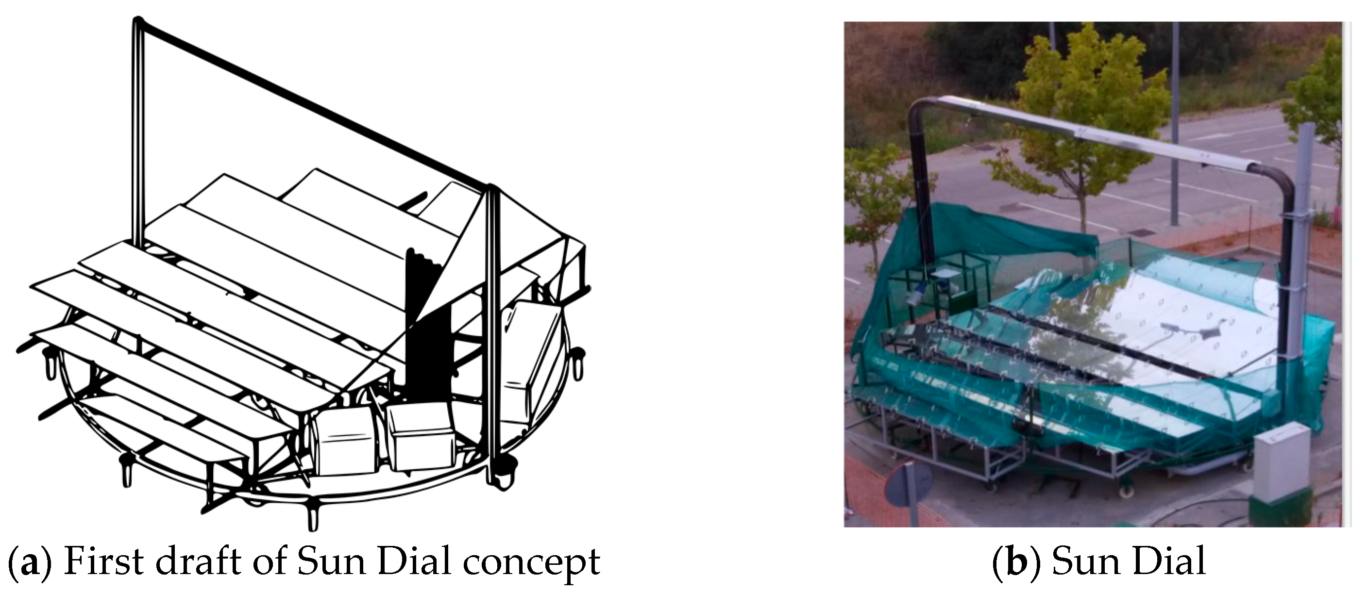
2. A New Concept of a Solar Field. The Rotatory Fresnel Collector or Sundial

2.1. The New Concept

A new concept has been developed, which has been given the name of Sundial. It is intended to achieve commercial competitiveness in the area of concentrated solar power (CSP). The aim is to concentrate the solar radiation following the example of a sun clock and, using much simpler and cheaper mirrors, to significantly reduce the cost of generating electric energy by solar thermal energy.
This workaround is based on the development of granted patents ES2537607 [50], ES1138715U [51], ES2596294 [52], and ES2578804 [53].
Sundial (“Reloj de Sol”) uses longitudinal cylindrical mirrors, with the same focal axis, fixed on a platform that rotates horizontally like the shadow of the pointer in a Sundial [54]. All solar radiation concentrators that use rotating mirrors to focus radiation involve the use of considerable weights, for rigidizing the structure.
With this new configuration, the amount of structural material in the solar field is much lower, as will be shown in Section 5Economic Analysis.
The first planned design is shown in Figure 2a, and the final constructed prototype can be seen in Figure 2b. The absorber will always be in the same relative position to the mirrors, resulting in a stiff and simple system.
Figure 3 shows a side view of the elements that are part of the prototype and their arrangement and relationships.
-
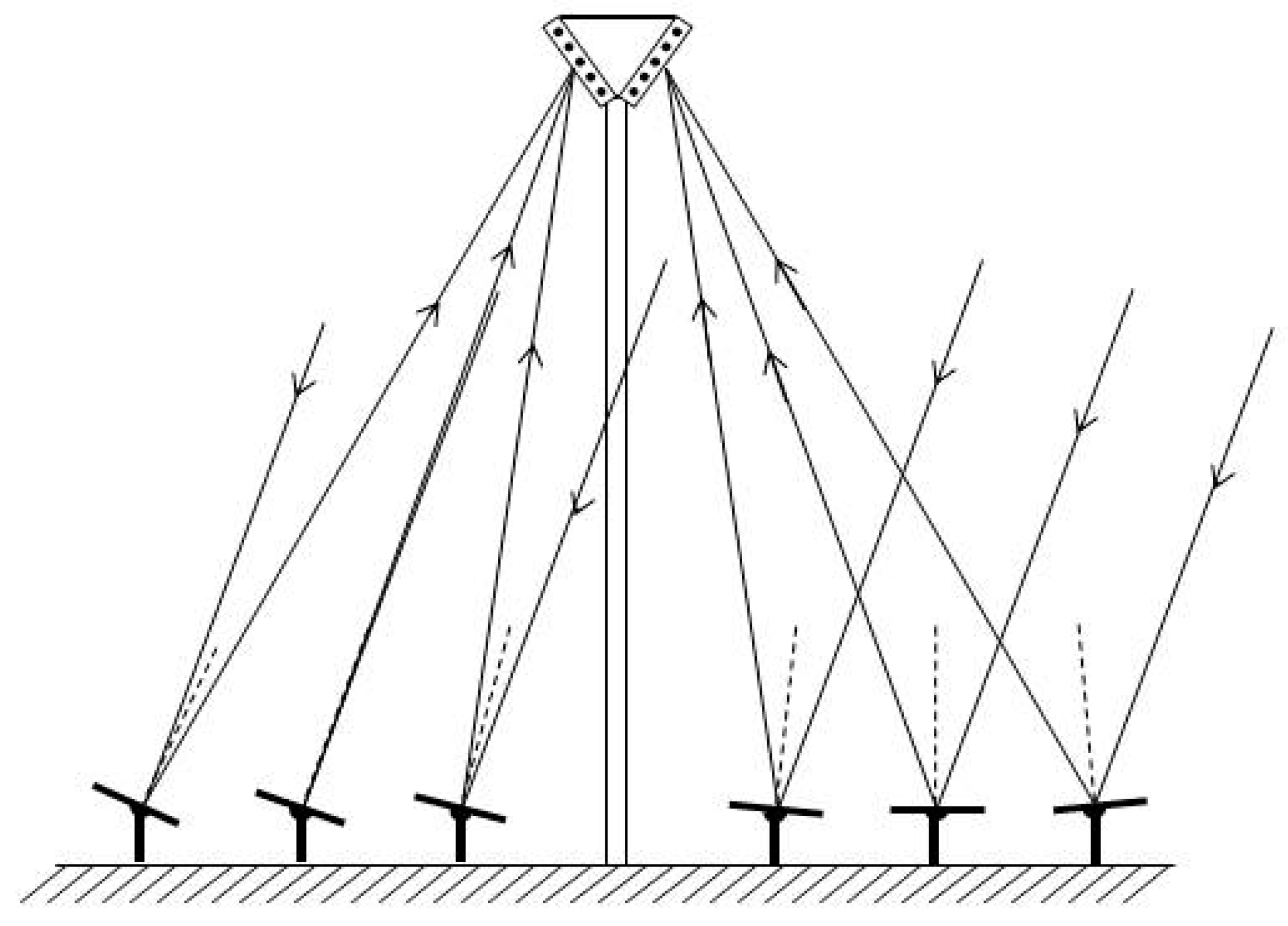
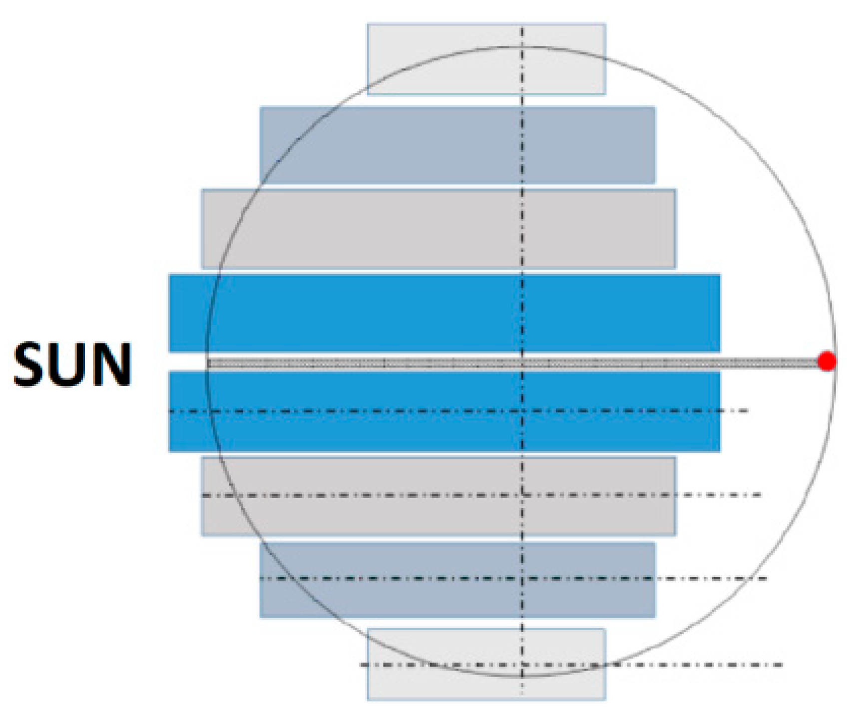
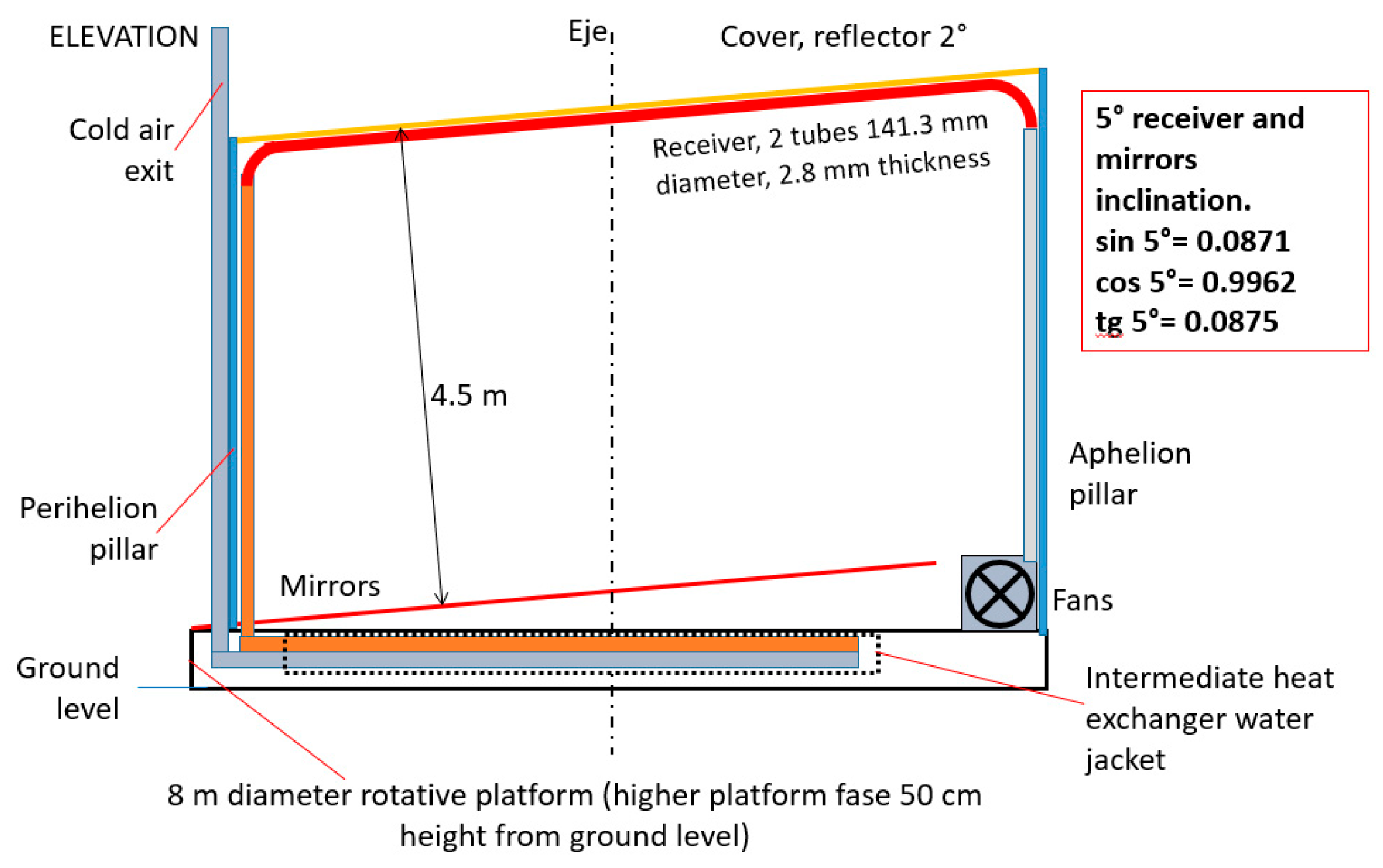
The absorber position corresponds to the intersection of the narrow bundle of mirror focal lines.
-
Considering the platform as the reference system means that the only change will be the zenithal angle of the sun, which will always be in the symmetry plane.
-
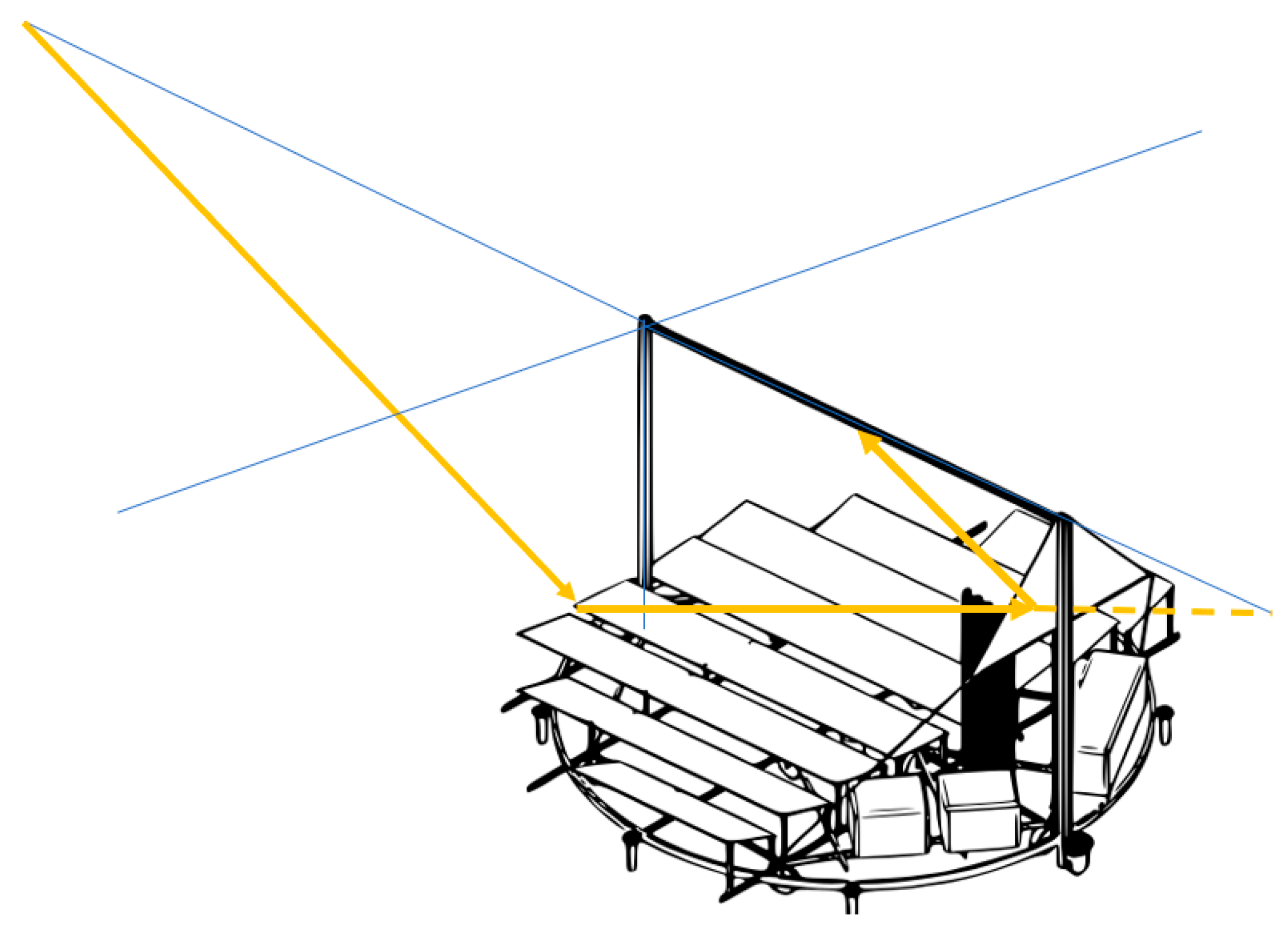
The incidence longitudinal angle has to be taken into account because it produces end losses in the opposite side to that of the sun’s position. Those losses can be reduced by tilting the mirrors towards the sun, but this is not sufficient for avoiding those losses. It is necessary to include some vertical mirrors close to the back end of the symmetry plane.

2.2. Coherent Integration of Elements to Oobtain an Optimum Configuration

The first step to assess the validity of this concept was centered in the mirror field, i.e., the concentrator. It is worth noting again that the main advantage of this concept is that the relative position between any mirror and the focal line of the receiver does not ever change. This conveys a strong reduction in focusing uncertainties, but it requires the detailed development of the elements to fix the mirrors in the platform.
There are some considerations to keep in mind in relation with the platform; it must be considered in several aspects:
-
The platform size does not have strict limitations, other than the tilting angle.
-
A trade-off is needed between the benefits of tilting the mirrors and increasing the platform size in order to obtain the optimum configuration.
The platform is moved by several wheels. In relation to this, as the first design, we propose a group of wheels that will roll over a track.
The track of the wheels can be either horizontal or conical:
-
A conical configuration would ensure that the vertical axis is kept fixed.
-
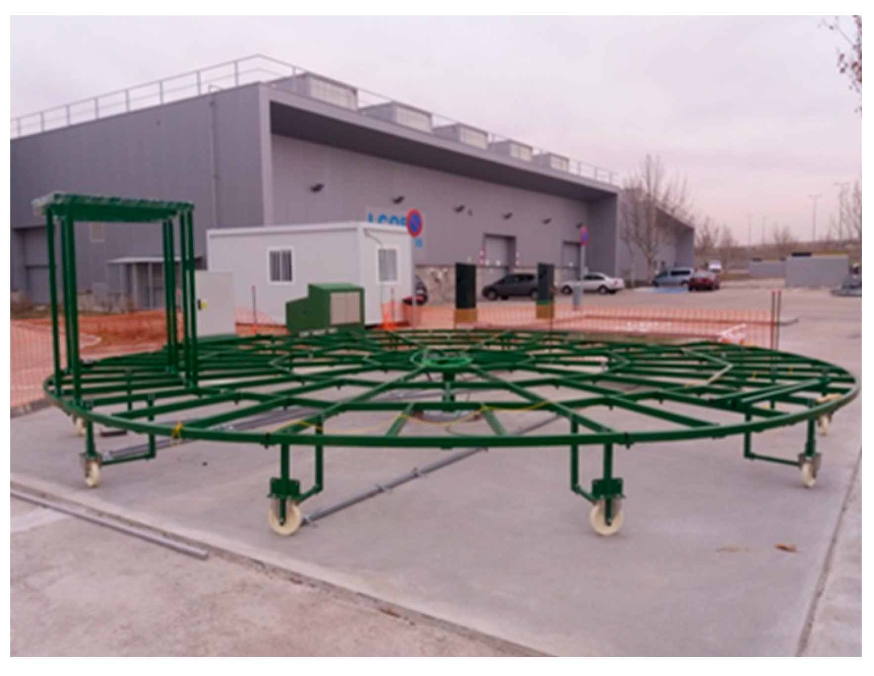
However, the accuracy required for the sun tracking is attained with commercial wheels for scaffoldings and other industrial applications. Those wheels (40 cm in diameter) withstand 500 kg with a width narrower than 20 cm, which means that the pressure on the wheel trail can exceed 50 N/cm2, and a suitably resistant round track is needed to that end.
One of the essential parts of this new solar field concept is the configuration of the mirrors. We use thin flat mirrors that are very cheap compared to mirrors used by parabolic trough collectors (permanent curvature is needed for the application). These mirrors require a special but simple device that bends these flat mirrors in the Rotatory Fresnel collectors (RFC). This device can modify mirror curvature as required.
Due to its relevance and novelty, this part will be explained in detail in the following section.
Its main advantages over other linear concentrators are that not all the mirrors need tracking, just the horizontal platform. This ensures the simplicity of the system, and less material means a cheaper system.
During the construction phase, various forms of rotation or turning of the platform were studied, and we finally opted for a central axis supported by bearings and a set of wheels near the outside of the circumference. Two of these wheels have a coupled motor to carry out the movement of the platform.

3. Solar Concentration Capacity with Flat Mirrors

One of the main features of the RFC is the use of inexpensive standard flat mirrors, which are bent on the rotatory platform itself.
This section begins with the explanation of the bending mechanism. It includes the study of the mirror deformation and the interaction of the solar radiation with the bent mirrors to generate an appropriate reflected radiation impinging on the receiver.

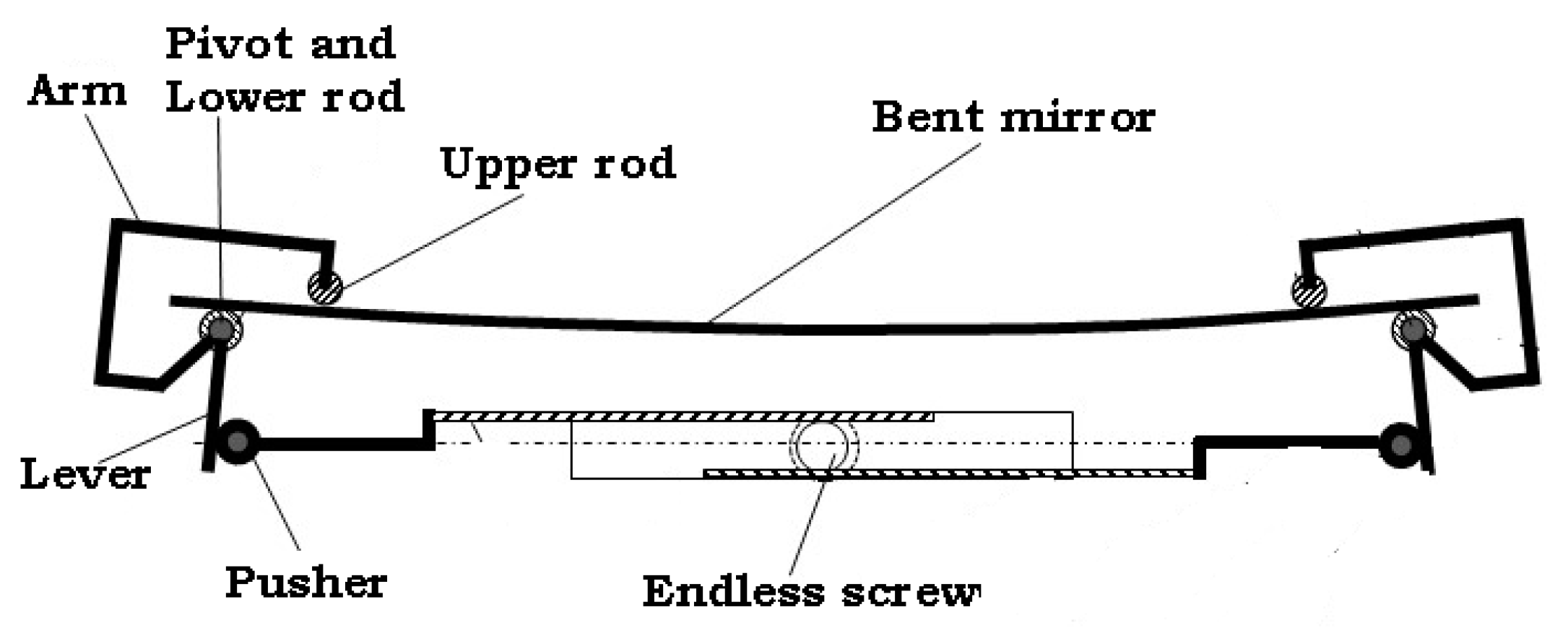
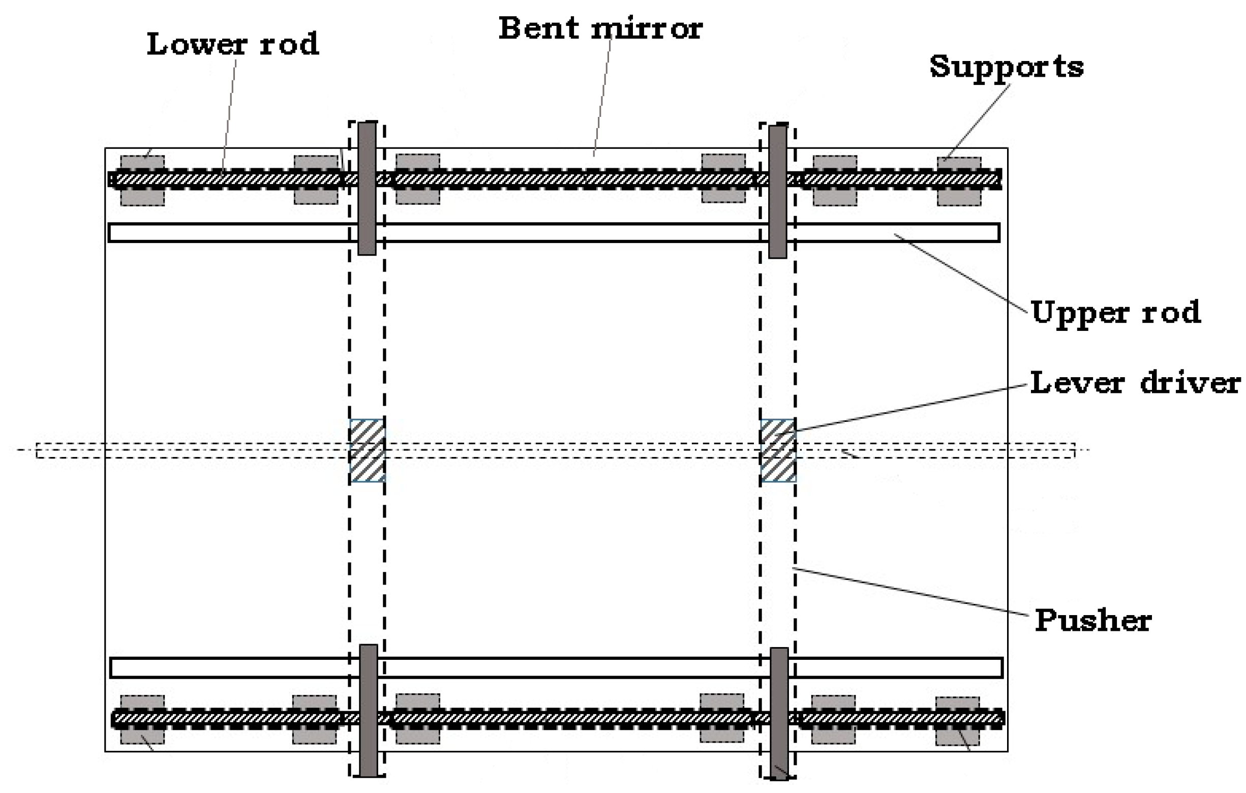
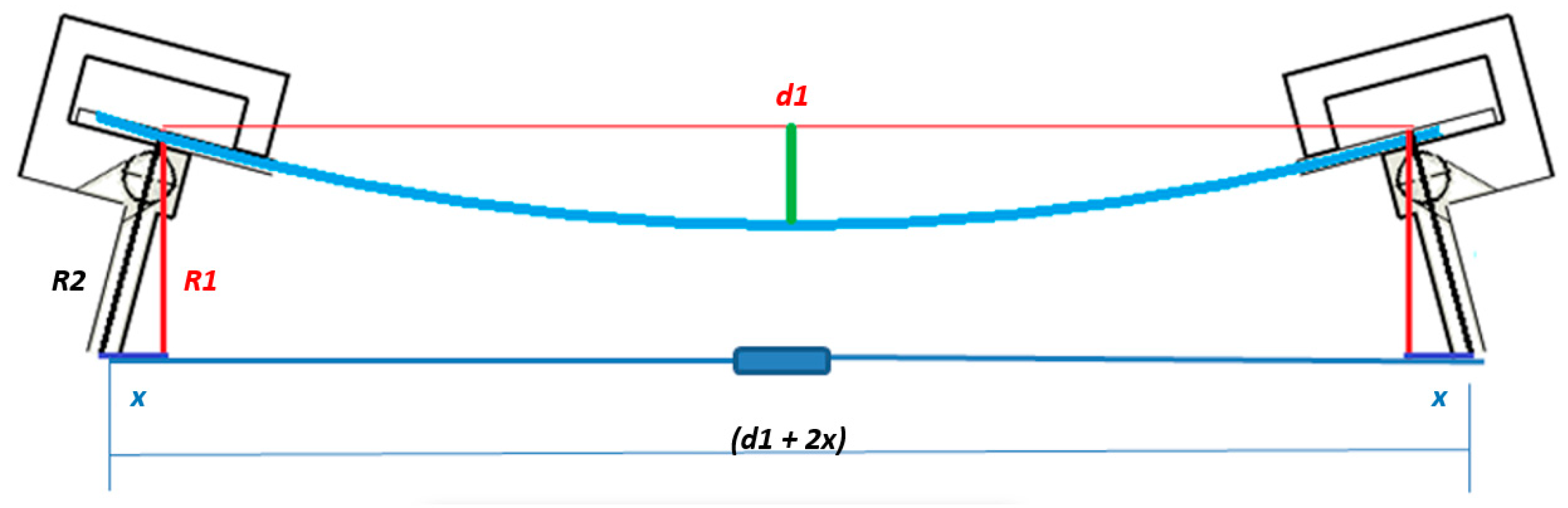
3.1. Bending Flat Mirrors

In order to guarantee the construction, handling, and assembly, each longitudinal section of mirrors is made up of smaller, simple mirrors. Flat mirrors can be bent in order to improve their concentration features. This is done by applying an external pair of forces in the lateral edges of the mirrors. A simple bending device is used for this purpose, made of a double bar with a lever at each end, as depicted in Figure 4.
Moreover, the weight of the mirror must be considered in both the transversal and longitudinal directions. Actually, there must be some rods in the longitudinal direction to avoid excessive bending in that direction.
It should be remembered that the mirrors will have some tilt in both directions, and the deformation by weight will be decreased by the cosine of the tilting angle. As the tilting will usually be lower than 22.5°, the minimum effective gravity required to bend the mirror will be 9 m/s2 (which represents a second-order effect).
The bending, or ‘bending system’, of the mirrors was registered in the patent ES-2596294-B2 [52] and it is described as follows:
-
A way to apply a bending moment at each beam end is depicted in Figure 5 and Figure 6.
-
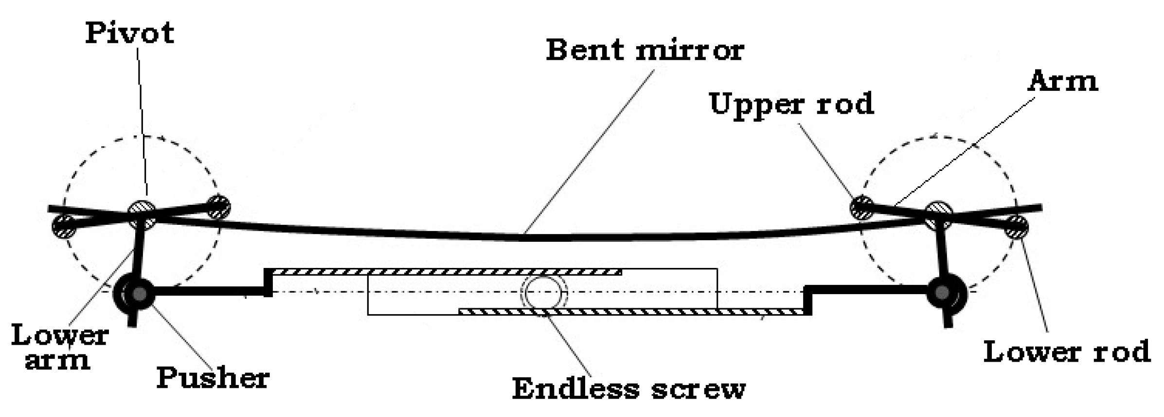
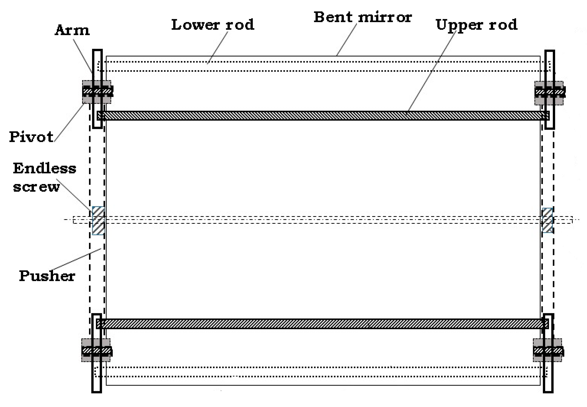
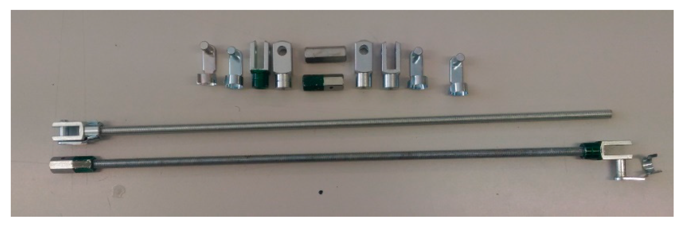
There are two rods, one at each side, above and below the glass of the mirror; they are rotated until reaching the slope predicted by the former analysis. Both rods are pushed by a radial arm turning around a pivot. Once the mirror has obtained its corrected curved shape, the pusher is kept fixed.
Figure 7 and Figure 8 show another way for applying the same bending moment. In this case, the rotating levers are placed on the sides of a mirror. The rotating axis is in the rear face of the mirror and the lever acts on the upper rod.

3.1.1. Transversal Deformation

Deformation of beams and plates is well known in the field of material resistance; therefore, a simplification by means of a 1D beam can be used to explain the phenomenon: the beam under study will be a cut of the mirror from Figure 4 with the XZ plane. Therefore, the length of the beam will be the width of the mirror (L). The origin of the beam will be situated in the center of the cut, i.e., in the center of the mirror cross-section. This origin helps to normalize the beam with a value of −1/2 at the left end and 1⁄2 at the right one.
The dependent variables of interest are the bending moment, M; the slope of the bent curve, θ; and the ordinate of the curve, z, which will be expressed as a function of the coordinate x.
The equations of the bending moment M(x), the slope of the bent curve θ(x), and the ordinate of the new shape z(x) are:
M e x t ( x ) = M 0
θ e x t ( x ) = L M 0 E I x
z e x t ( x ) = M 0 L 2 2 E I ( x 1 2 ) ( x + 1 2 )
where E is Young’s modulus and I is the moment of inertia, defined as follows:
I = b a 3 12
where b is the length of the facet and a is its thickness.
In addition to the external momentum, the influence of the mirror weight has to be analyzed by means of Equations (5)–(7), where p is the weight per unit of length:
M w ( x ) = p L 2 12 [ 6 ( x + 1 2 ) ( 1 2 x ) 1 ]
θ w ( x ) = p L 3 6 E I ( x + 1 2 ) ( x 1 2 ) x
z w ( x ) = p L 4 24 E I ( x + 1 2 ) 2 ( x 1 2 ) 2
Based on Equations (5)–(7) it can be seen that the largest bending moment at x = 0 is pL2/24 and the absolute maximum value at x = 1/2 (the end of the beam) is −pL2/12. Furthermore, there is a change of concavity when the bending moment becomes zero at x = 0.2882 and x = −0.2882.
The total deformation of the mirror will be the sum of that caused by the external bending moment and that caused by the mirror weight. As mentioned, the influence of gravity will always be present, and the deformation caused by the external bending moment must be sufficiently large compared to that caused by the mirror weight.
We define the ratio of ordinates as (8)
z w   z e x t = 1 G ( x 1 2 ) ( x + 1 2 )
where G, the ratio of moments, is defined as (9):
G = M 0 p L 2 / 12
Note that, in absolute value, this ratio is always smaller than ¼·G. So, ratios of moments larger than four will obtain acceptable shapes of the bent mirrors.

3.1.2. Radius of Curvature

It has been shown that the deformation of a mirror under the effort of a bending momentum corresponds to a parabola (Equation (3)). A parabola shape can be approximated to a circumference in points close to the origin if the focal distance is twice the radius of the circumference. This simplification will allow us to relate the deformation and the momentum (10).
R = E I M 0
The equation of a circle with the lowest point in the origin (0,0) and radius R is as indicated in (11).
y c i r c ( x ) = R R 2 x 2
The equations of a parabola with the same lowest point and focal point (0,R/2) is expressed in (12).
y p a r a b ( x ) = x 2 2 R
Calculating the error as per (13), the error depends on the ratio x/R. Of course, the lesser the ratio x/R the lesser the error will be.
e R ( x R ) = | y p a r a b ( x ) y c i r c ( x ) | | y p a r a b ( x ) |
In the case of a beam with length L, the error in considering the ratios of curvature to define the deformation shape will be less than 0.4 % if the ratio L/R is less than 1/4, which will be true always for this application.

3.1.3. Longitudinal Deformation

By example, for a one-meter-wide mirror that is 5 mm thick and indefinitely long, knowing that Young’s modulus E of glass is about 70 GPa, for bending radius of 10 m, this corresponds to a focal length of 5 m. Based on Equations (4) and (10) the bending moment per meter length would be M0 = 73 N·m.
This means that the rods, shown in Figure 5, Figure 6, Figure 7 and Figure 8, must bend the facets along the mirror boundary with enough strength and this bending must be provided by the rods at the contact points in each cross section (see Figure 5 and Figure 6). If it is considered that the distance between those points must be less than 10% of the said width to avoid more perturbations, then for 8 cm of distance between parallel rods the force applied per meter of length will be 875 N.
The momentum produced by this force must be as uniform as possible along the longitudinal direction of the mirror, that is, a rigid enough rod is needed but the final simplified solution does not include this rod.
If a hollow steel tube is selected with an elastic modulus of 220 GPa and the maximum deflection is set at 0.2 mm for a separation between consecutive torque levers of 0.5 m, then Equation (7) can be used to calculate the minimum moment of inertia needed: 0.324 cm4.
The moment of inertia for a tube of outer diameter D and inner diameter d is expressed in Equation (4).
I = π 64 ( D 4 d 4 ) .  
A rod with D = 2 cm and d = 1.6 cm would be valid as the moment of inertia is 0.464 cm4, and thus the maximum deflection would be 0.135 mm.
In this section, it has been shown that it is possible to bend flat mirrors and obtain bent mirrors with a circular cross-section with a suitable radius of curvature. The simple behavior of these techniques is fundamental for achieving cheap solar fields.

3.2. Concentration with Flat Bent Mirrors

Mirrors with parabolic profiles allow us to concentrate rays parallel to the symmetry axis into a focal axis or point; however, the rays falling on linear reflectors, such as the RFC or standard Fresnel, are not parallel to this symmetry axis.
Figure 9 shows a scheme of the mentioned reflection: the mirror, characterized by its width (L), radius of curvature (R), aperture half-angle (γ), and tilt (α), reflects the solar radiation into an area where the absorber will be placed. The focal point is the main reference of this area, and the length between this point and the mirror central point is named the focal distance (identified by V).
The focal area is composed by the intersection of the reflected rays from the different points of the mirror. It can be seen in Figure 9 how the rays do not converge into an axis or point, but into several ones. The focal plane is formed by the intersection of the reflected rays from both ends of the mirror and the central point between the intersections of the reflected rays from the center and both ends of the mirror. The intersection of the reflected rays from left and right is a point, always placed closer to the symmetry plane than the focal point, and below this one.
Figure 10 shows the position of the left-right cross-point for different values of γ, taking the focal point as the origin of coordinates, for a specific mirror with R = 20 m, α = 15°, and focal distance V = 9.66 m. The distance between the focal point and the reflected beam at the focal plane is below 3 cm for the maximum considered aperture half-angle, 3°. The rest of the distances at lower apertures will be even smaller.
The distance between the focal point and the reflected beam at the focal plane is below 3 cm for the maximum considered aperture half-angle, 3°. The rest of distances at lower apertures will be even smaller.
It must be taken into account that the solar radiation comes with an aperture of about 0.0093 radians, so the reflected rays due to the sun shape would be distributed along a 9-cm segment for this specific case. This means that errors due to natural factors have more influence and errors due to the use of cylindrical mirrors can be even negligible if the radius of curvature is adequately chosen.
As previously mentioned, the parabolic shape of the mirror (approximated to a cylindrical shape in the domain of this application) will be slightly modified by the influence of gravity. The error can be calculated as (15) indicates.
e s l o p e ( x ) = | d d x z w ( x ) | | d d x z e x t ( x ) |
The maximum slope perturbation appears approximately at a distance L/4 from its center, which results in an error equal to 12/32 × G.
Introducing the slope of the circumference at x = L/4, the maximum slope perturbation is obtained as (16).
S m a x = 3 L 32 G R
Linear Fresnel reflector optical performance is 11–23% lower than that of a parabolic trough collector’s reflector [47]; however, the proposed configuration is more competitive as it manages to reduce costs by using simpler and lighter structures, reducing the amount of material used and using common mirrors. The cost reduction, as can be seen later in Section 5, is greater than the reduction in optical performance indicated above.

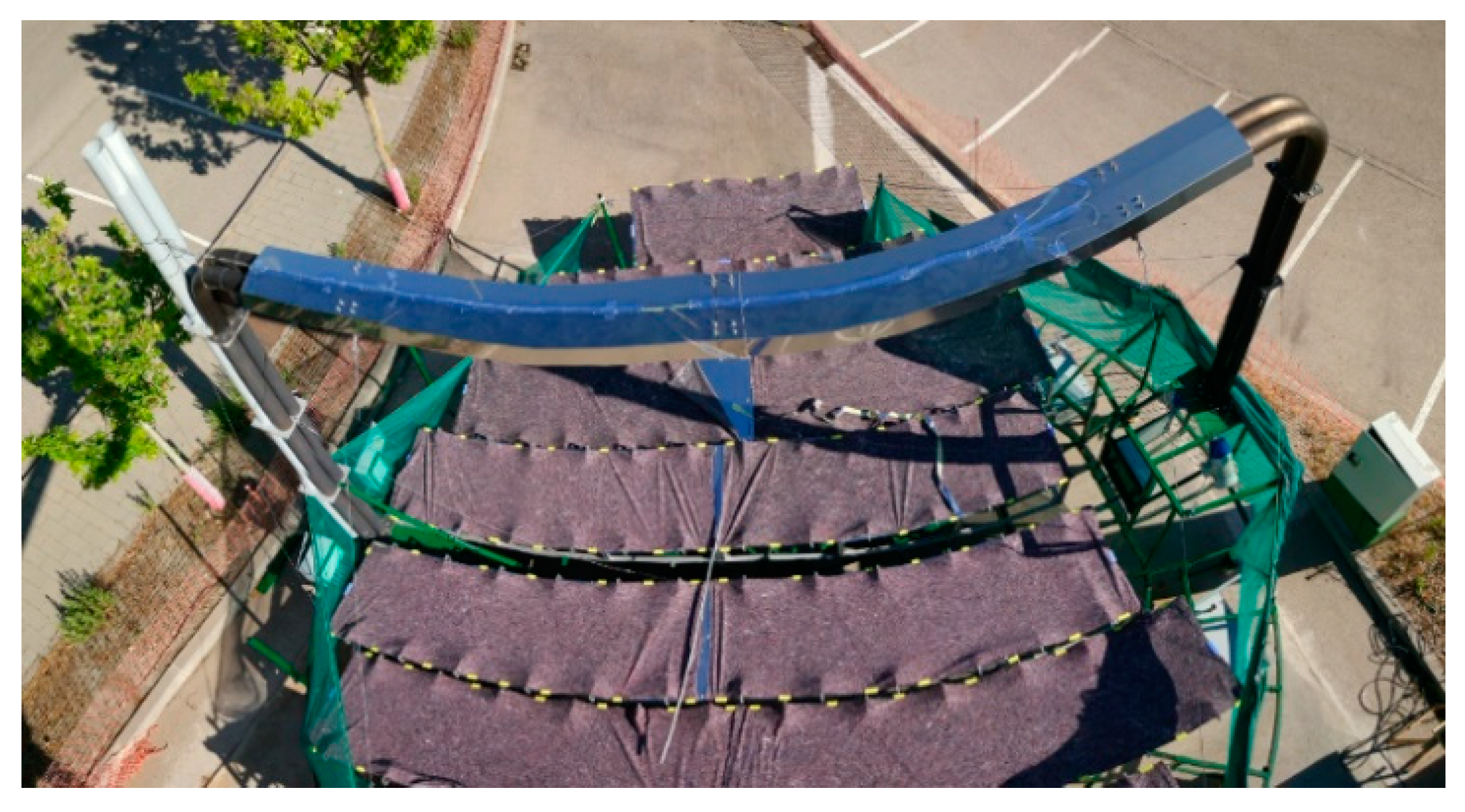
4. Application Example: Sundial

In the development of the present prototype, a Thermo-economic optimization of solar thermal devices was applied through the coherent integration of technologies [55]. The concept of “thermal coherence” was introduced by Rovira and Martínez-Val [56], and it is a tool actually suited for Solar Thermal design, because this type of design can easily be decomposed in modules with clear functionality, which can be characterized by an “energy efficiency” value and a unitary cost.
In [48] the experimental facility of the Sundial concept was introduced; it is a small-scale prototype that has been built in the Tecnogetafe campus of the Universidad Politécnica de Madrid [21], with a very reduced budget. The total amount invested in the development of the prototype was EUR 65,756 for a nominal power over 30 kW with a final temperature above 300 °C, and nearly 40 m2 of mirrors spread over eight stripes.
Sundial is a development of the GIT research group of the Universidad Politécnica de Madrid with funds and collaboration from the Fundación Para el Fomento de la Innovación Industrial, F2I2 [57]. The main features of the prototype are summarized in Table 1.
The solar field can be broadly divided into two parts, the concentrator and the receiver. The following paragraphs focus on the concentrator, where direct solar radiation is concentrated onto a focal spot via reflection (mirrors).

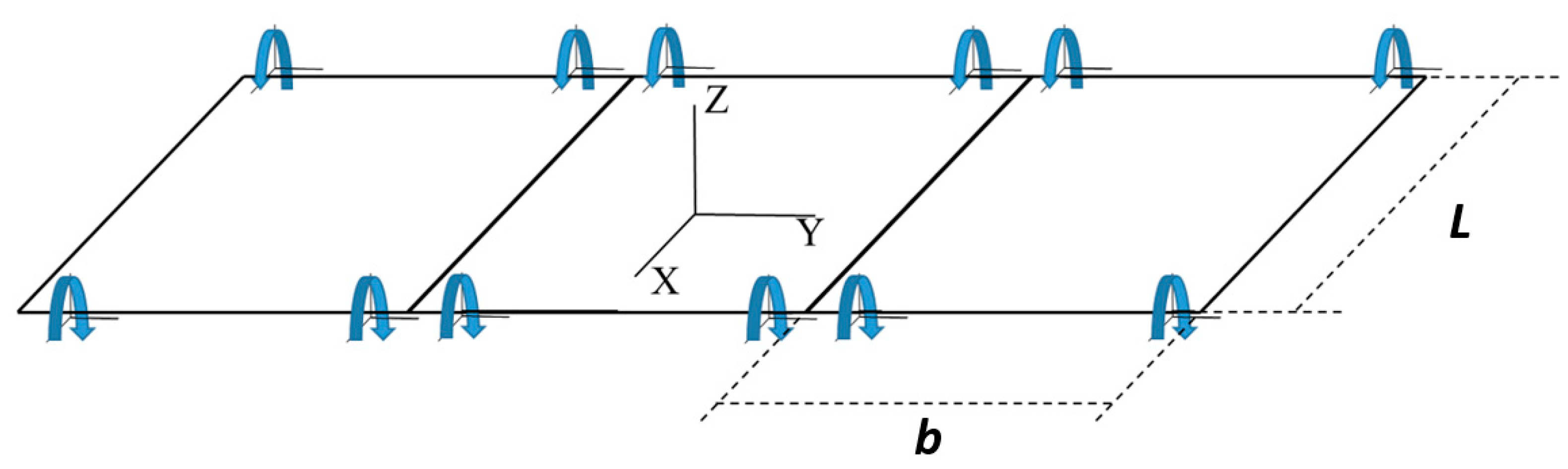
4.1. Solar Field Layout

In the reference system used in this section, the perihelion of the prototype platform is located at the coordinate (0,0,0), the (x, y) plane corresponds to the horizontal surface of the platform, and the plane (y, z) is the plane of symmetry. The receiver’s central focus line is in this plane. The ‘Y’ axis inclination angle of the mirror field is 5° (Figure 11).
The relative base position for the mirrors can be seen in Figure 12. The position of the mirrors was calculated to ensure that the axis of each row of mirrors is located at a distance equal to the focal distance from the receiver. To avoid the interference of the reflected solar beams, the necessary inclinations and separations between rows of mirrors were previously calculated.
To verify that the calculations are correct, we used 3D mechanical modeling software, in which we transferred the mirror’s position data. This allowed us to verify that the axes were correctly aligned over their axes and that the angle of inclination of each mirror corresponded to the initial design data.

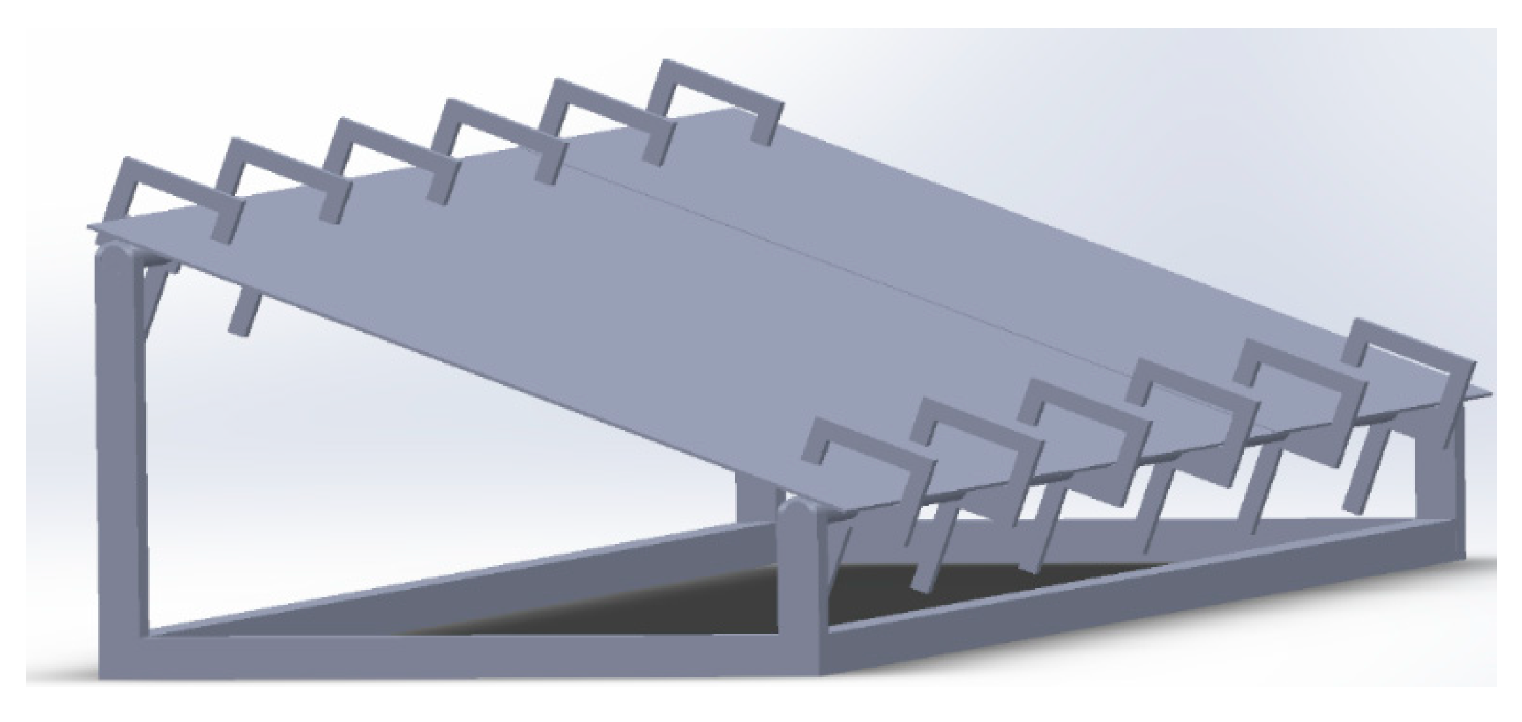
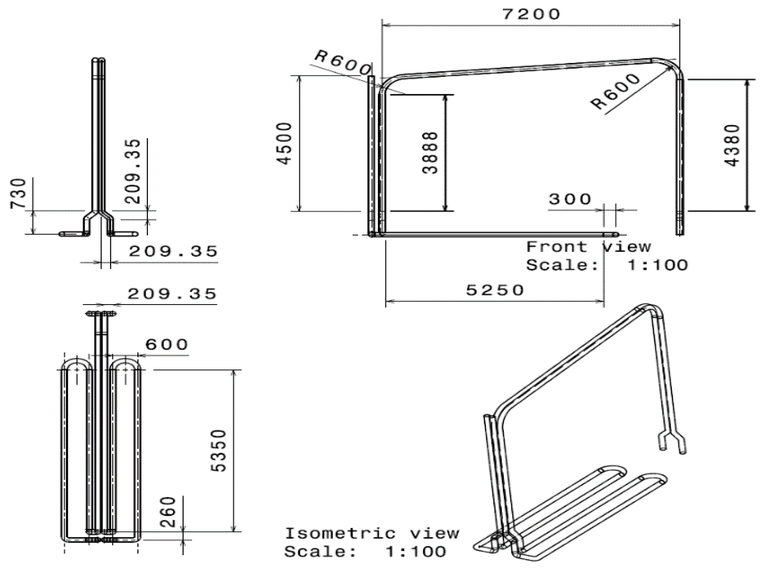
4.2. Mirror Support Structure

As already indicated before, one of the advantages that characterizes this prototype is the simplicity and robustness of the devised system, in which the support for the mirrors is static since the entire platform is moving and the mirrors are not.
This allowed us to choose a robust quick-assembly system that considerably reduces construction times. The mirror support structure prototype was made of Bosch Rexroth aluminum with a 45 × 45 mm profile; this profile can be found on the manufacturer Bosch Rexroth’s website with reference 3842992427 [58].
The use of this type of aluminum structure is not the most economical solution, but it is the solution that allows greater freedom, versatility, and time savings to build a prototype. For a final industrial solution it would be replaced by cheaper options.
To guarantee a homogeneous movement of the mirror folding system, a ribbed round tube, a Bosch Rexroth 28-mm round tube, was chosen (ref: 3842996191) [58]. The profiles and the axis of the clamps were fixed to the structure by means of a part designed for this purpose.
In summary, with all the aforementioned conditions, a structure was built that guaranteed that the mirrors had an inclination of 5° in the Y axis (equal to the inclination that had been given to the receiver) and an inclination in the X axis that increased as it moved away from the axis of symmetry to maintain the focal length on the receiver. This structure had the shape and arrangement shown in Figure 13.

4.3. Mirror Bending System—Model Design

A main advantage of the prototype is the use of cheap, flat mirrors. In order to use this type of mirror it is necessary to develop a system for bending the mirrors. This is the application of patent No. ES2596294 B2 from [52]; the variant used was “the variant of conformation of the clamp, with arm in C”, shown in Figure 7. Then, the first element to design was the clamp of Figure 14.
For the calculated sizes of the mirrors, the point of contact of the clamp that supports the mirror is over a rotating axis at 5 cm from the inside wall of it (with at least a 5-mm safety margin). Figure 15 illustrates the perfect operation of the system.
The solution provided and realized to guarantee the bending of the mirror and obtain the curvature (which was already calculated) involved the use of a set of 10 mm threaded rods with clockwise and counterclockwise nut rotators and steel short clevis fasteners. The elements that are part of this subsystem are shown in the Figure 16.
For each mirror, it was verified that the deflection was the same as the value calculated in the design phase. This was done with a tool made specifically for the task and a dial indicator with a plunger.

4.4. End Losses Solution

The place where the prototype was built presented a handicap due to the latitude. The prototype was built in Getafe (Madrid), Spain, located at latitude 40.2722406N, which means that the maximum solar elevation was around 73.2° during the summer solstice, as can be seen in elevation charts.
This situation means that during much of the year and early in the morning and late afternoon there are large losses due to the aphelion, called end losses [59,60].
The reduction of the end losses is crucial to improve the performance of the system.
As an example, the central row of mirrors has a relative position with respect to the receiver of +0.5 m; for a solar elevation of 40° we calculated that the reflection of sunlight appears at 4.42 m, that is, half of the receiver does not receive solar radiation under these conditions. To mitigate this problem, it is decided to use a set of vertical mirrors, perpendicular to the platform, located in the aphelion, which redirect the solar rays, which would be lost, back towards the receiver. Figure 17 shows this solution schematically.
The use of the closing mirrors as proposed, also allowed us to avoid unwanted effects on the environment, such as the one shown in Figure 18, in which a branch—of which the height coincided with the focal length of the solar field that was behind the aphelium—was calcined by the solar concentration.

5. RFC Component Description and Costs

Rotatory Fresnel collectors simplify the concept of concentrators. A Parabolic trough collectors (PTC) or standard lineal Fresnel collector can achieve better performance, particularly in the concentration factor, and can intercept more radiation per unit of the mirror surface than a horizontal RFC. However, tilting the RFC improves this interception performance. As the main first step in harnessing solar radiation is concentration, the first phase of the development of this new concept was determining the concentrator features, without forgetting the problem of cost. These objectives led us to consider CSP plants as a combination of:
  • Industrial materials and components (high level of maturity and low prices);
  • Avoiding complex assemblies and very specialized operations;
  • Reducing the required weight of the main materials.
This section presents a summary of the main items of the prototype in order to make a first comparative estimate of the advantage of applying the Sundial concept due to the savings it achieves in terms of the necessary investment costs.
It is recommended to analyze in depth the economics of the RFC prototype for a better understanding of the technology. The total costs of the prototype amount to EUR 65,756. However, as it is a prototype, not all expenses are attributable to the different areas considered; for example, sometimes it is necessary to follow a trial-and-error process and acquire equipment or materials that are later discarded. Considering only the elements that have been used in the final prototype and discarding the rest, the expenses are summarized in the last column of Table 2.
The costs reflected in the different tables are the costs of equipment and materials purchased from local retailers. This means that in an industrial construction with economies of scale, significant cost reductions can be achieved.
The prototype construction costs have been divided into two main groups—the steel base structure and the platform movement system on the one hand and the rest of the mechanical elements, support structures, receiver, and mirror field on the other.

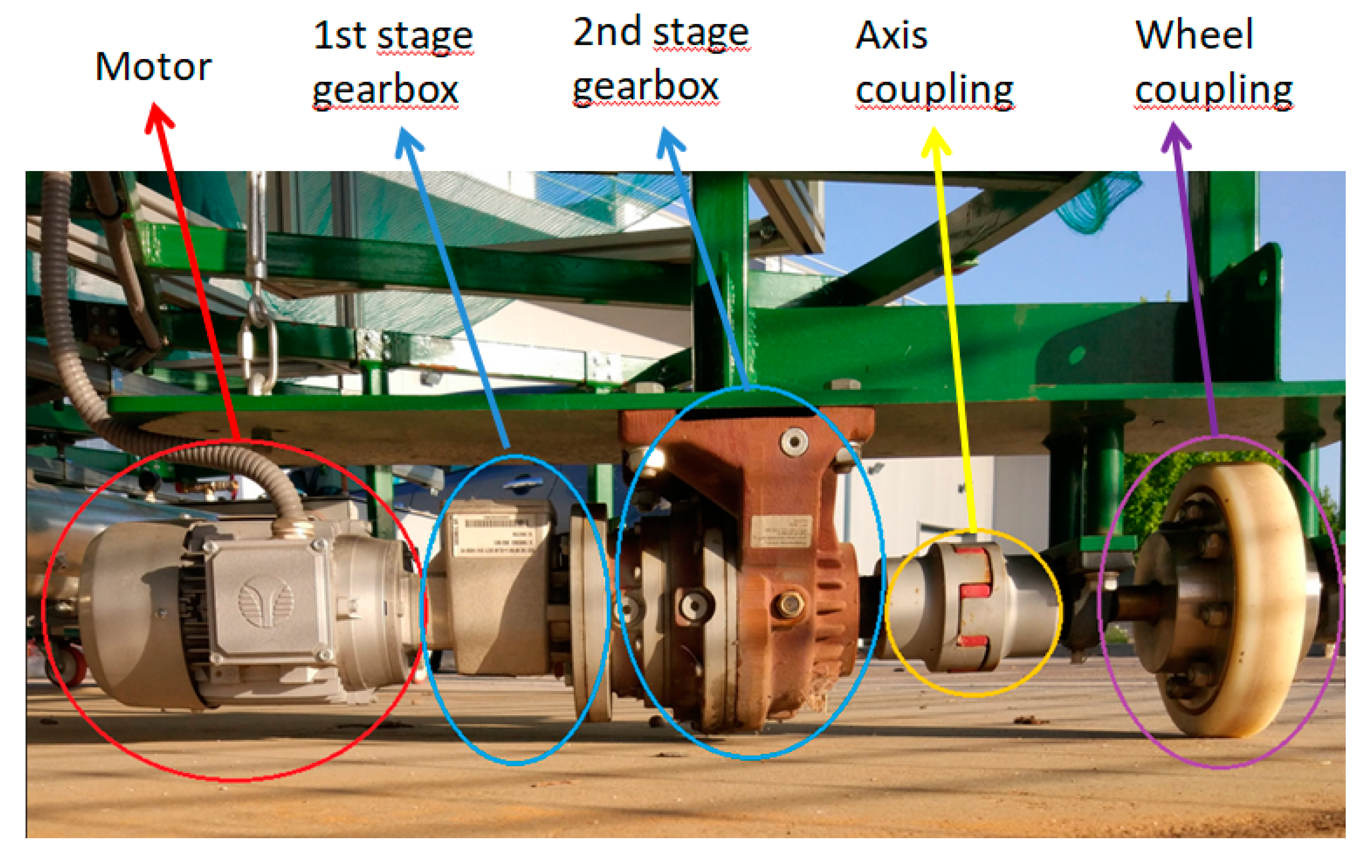
5.1. Platform Base and Traction System Cost

The main elements of this budget item were the steel structure, the platform itself, the centering and guiding system and the motor or traction system that guarantees the movement of the platform.
The platform was built with rectangular steel tube of 60 × 40 mm; it has a round shape with a diameter of 8 m, as can be seen in Figure 19.
For the construction of the traction system, it was necessary to reach a compromise between the speed of movement during the periods of operation of the platform (angular speed equal to the apparent speed of the sun) and the speed of movement to bring it from its final position at the last time in the afternoon to its starting position to start a new day. The torque required to move the platform has also been taken into account. As a result, the set shown in Figure 20 was built. Two of these sets were installed.
The total cost related to the platform base and traction system are show in Table 3.

5.2. Mechanical Parts Except Base and Traction System

The second important investment group is related to the mechanical parts of the receivers and solar field.
The receiver tube is a self-supporting tube to which the fluid inlet is connected, in this case air, and configures an exchanger at its outlet to the outlet chimney. Figure 21 show the pipe distribution and its size.
The second main cost of this section is the mirror field formed by cheap and flat mirrors, the structure that gives the mirrors shape and allows us to obtain the curved mirror and its fixation to the base. Figure 19 shows a top view of the solar field; in this case, the solar field is covered to avoid the unwanted effects of end losses on the environment, as can be seen in Figure 22.
Mirrors are the first large component interacting with the solar radiation. Flat mirrors have a weight in the range of 10 kg/m2 to 15 kg/m2. The mirrors were acquired from a local manufacturer [61] and a distributor with retail prices 14.45 EUR/m2, which can translate into a cost of less than 10 EUR/m2 for a construction company with a large volume of purchases.
The costs related to mechanical parts are show in Table 4.

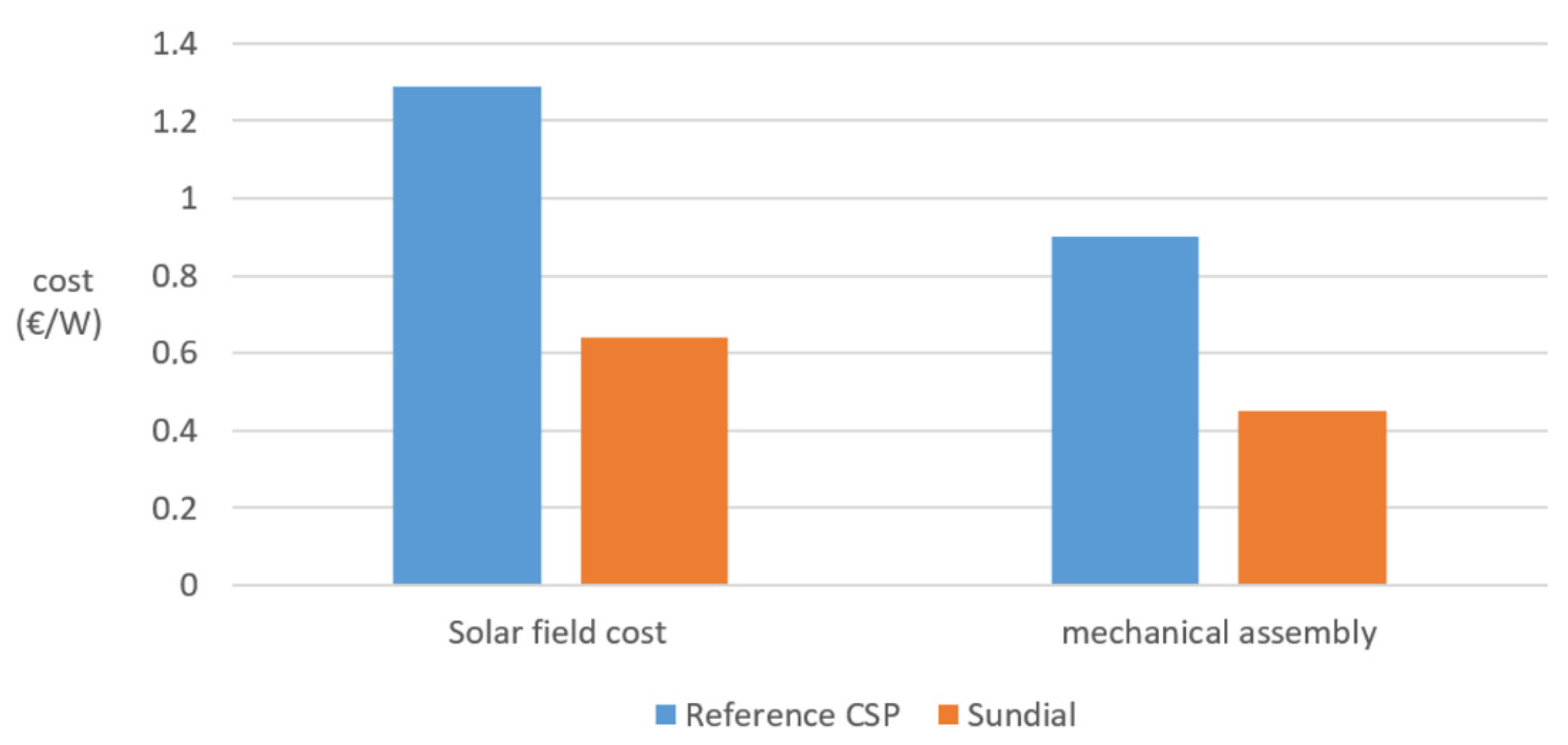
5.3. Comparison with Common Parabolic Trough

To give an idea of the advantage of adopting a Sundial model in the construction of a solar thermal plant, a coarse comparison of the main construction costs of a conventional plant is shown in this section, considering the different components used in each type of solar thermal collector family. First, we have selected real construction data from an engineering consulting company (RENOVETEC) [62] working in the sector. These data are summarized in the Table 5, presenting the real construction cost data for a 50 MW CSP in 2016.
Based on these data, we can see that the two main costs are the solar field, at 1.29 EUR/W, and the mechanical assembly, at 0.90 EUR/W.
In the Sundial prototype of a 30 kW system, the total cost of the solar field and support was EUR 19,041.00, that is, a solar field cost of 0.64 EUR/W. The cost of the mechanical assembly was 13,467.00 EUR, that is, 0.45 EUR/W. Figure 23 graphically shows the comparison of these costs.
It is worth pointing out that a prototype does not have the advantages of large-scale economy, but we must also admit that the prototype should also be charged with a fraction of the research effort. Indeed, this belongs to the learning curve of the initiative, that must be shared by all the followers, although this sharing starts with the prototype. Furthermore, we must remember that a horizontal RFC will collect around 20% less energy per mirror area than a PTC [47]. Other estimations about the Sundial’s overall energy production give a range of 70–85% of the production of a parabolic trough collector [63].
Based on the previous data, the savings in construction costs are very high, up to 38% in solar field and mechanical assembly items. If we calculate the total savings over the total cost of the installation, this would mean an overall saving of 20%.

6. Results and Discussion

The main goal of the prototype was accomplished from the technical point of view—to be able to concentrate the solar radiation in the receiver. In addition, the prototype obtained local temperatures over 300 °C.
The main objective of the construction of the prototype was to analyze the concentration capacity; therefore, air was used as a fluid and the thermal possibilities have not yet been studied. Moreover, the receiver configuration was far from optimal, because it was made of just two pipes, large enough to capture all the reflected radiation in order to better characterize the concentration features. Nevertheless, this configuration conveyed a significant drawback, because the radiating surface of the receiver was much larger than the active zone on which radiation impinges. This means that the surface for thermal losses is much higher than the surface directly heated by the concentrated radiation. In the next stage of development of this concept, a different receiver will be used, with a secondary reflector placed above a multi-tube receiver, as described in the Spanish patent ES 2397205.
Although the receiver requires a new design, it is worth showing the results of monitoring the temperatures in the receiver with thermocouples (Figure 24) and thermographic images (Figure 25).
Both the temperature measurements obtained through the data acquisition system and the thermocouples and by means of a thermographic camera demonstrated that the correct operation of the platform resulted in temperature measurements in the receiver above 300 °C. Note that the absorber on the receiver surface was not encapsulated in a glass vacuum cylinder, inhibiting convection losses. This is also a deficiency that will be addressed in the future. Additionally, a selective coating will have to be identified for the external painting or treatment of the absorber surface. In the prototype, some types of Nickel black were used, but the conclusions for making a final decision have not been reached yet.

7. Conclusions and Future Work

The Sundial prototype demonstrates that the construction cost of a solar thermal plant can be significatively reduced. For this first prototype, the savings in construction costs are up to 38% and applying this data to the total cost of the installation would mean a global saving of 20%. The prototype was built with a cost per installed watt that is significantly lower than the traditional costs of a conventional solar thermal plant.
The work in this line is far from finished because the prototype has not yet been connected with a suitable block of power. In the first steps of this project, the emphasis was put on the solar field and the validation of optic models, which is the specific part of a solar thermal power plant. At this design stage, temperatures up to 300 °C have been reached.
With the conceptual design of the project having been clearly defined, the first novelty in the construction of concentrating mirrors was developed, using simple flat mirrors. The flat mirrors were bent by applying external torques of force on the edges parallel to the axis of rotation.
The second main novelty was proposed for carrying out the tracking of the sun in a simple and robust way—all elements of the collector were placed on a platform rotating around a vertical axis.
The angular speed of rotation was equal to the apparent speed of the Sun in the azimuthal plane of the platform. The geometric relations among the mirrors and the receiver were kept constant over time.
The construction and the results obtained from this prototype have produced results that, together with new ideas and analytical developments, have led us to continue with this line of research, looking for improvements under the same technical spirit.
During the second half of 2021, the design and construction of a second prototype with two degrees of freedom will begin.
The best performance for the Sundial would be located in latitudes close to the equator due to its design and construction; therefore, increasing the degrees of freedom of the rotation of the mirrors by one would allow the system to increase the number of daily operating hours and its application in northern and southern latitudes.
The considered scope for this concept includes applications where the available space and the lack of solar-specialized maintenance are more relevant than higher temperatures/efficiency, such as in urban areas or in heat processes for industrial applications (heating and cooling by sorption cycles).
The next prototype experiments will include tests with different fluids cooling the receiver, in order to measure the thermal efficiency of the concept.

Author Contributions

J.C.-N.: Main paper wrtiter, prototype developer, concept development. J.M.-A.: Concept development, paper writing. J.M.M.-V.: Main idea and concept, theoretical approach. All authors have read and agreed to the published version of the manuscript.

Funding

This paper has been partially supported by the project “ACES 2030 CM: Energía solar de concentración” granted by the Comunidad de Madrid (Madrid regional government) and the European Structural Funds. ACES2030-CM project (S2018/EMT-4319).

Data Availability Statement

Not applicable.

Acknowledgments

Discussions with the rest of our Research Group (Grupo de Investigaciones Termoenergeticas-GIT) are greatly acknowledged.

Conflicts of Interest

The authors declare no conflict of interest.

References

  1. World Meteorological Organization. Available online: https://public.wmo.int/en/sun’s-impact-earth (accessed on 16 June 2021).
  2. Muneer, T. Solar Radiation and Daylight Models (with Software Available from Companion Web Site); Elsevier Butterworth-Heinemann: Amsterdam, The Netherlands, 2004. [Google Scholar]
  3. Castells, X.E. El Modelo Energético Español; Ediciones Díaz de Santos: Madrid, Spain, 2012. [Google Scholar]
  4. Muradov, N.Z.; Veziroğlu, T.N. Green path from fossil-based to hydrogen economy: An overview of carbon-neutral technologies. Int. J. Hydrogen Energy 2008, 33, 6804–6839. [Google Scholar] [CrossRef]
  5. Abbas, R.; Montes, M.J.; Piera, M.; Martínez-Val, J.M. Solar radiation concentration features in linear fresnel reflector arrays. Energy Convers. Manag. 2012, 54, 133–144. [Google Scholar] [CrossRef]
  6. Luque, A.L.; Viacheslav, A. Concentrator Photovoltaics; Springer: Berlin/Heidelberg, Germany, 2007. [Google Scholar]
  7. Benoit, H.; Spreafico, L.; Gauthier, D.; Flamant, G. Review of heat transfer fluids in tube-receivers used in concentrating solar thermal systems: Properties and heat transfer coefficients. Renew. Sustain. Energy Rev. 2016, 55, 298–315. [Google Scholar] [CrossRef]
  8. Shigenari, H.; Shuhei, S.; Ichita, K. Solar Thermal Receiver and Solar Thermal Electric Generation System. U.S. Patent 12/708, 17 June 2013. [Google Scholar]
  9. Clements, B. Energy Subsidy Reform: Lessons and Implications; International Monetary Fund: Washington, DC, USA, 2013. [Google Scholar]
  10. Forrester, J. The value of CSP with thermal energy storage in providing grid stability. Energy Procedia 2014, 49, 1632–1641. [Google Scholar] [CrossRef] [Green Version]
  11. Sangster, A. Massive energy storage systems enable secure electricity supply from renewables. J. Mod. Power Syst. Clean Energy 2016, 4, 659–667. [Google Scholar] [CrossRef] [Green Version]
  12. Vukosavic, S.N. Grid-Side Converters Control and Design: Interfacing Between the AC Grid and Renewable Power Sources; Springer International Publishing: Cham, Switzerland, 2018. [Google Scholar]
  13. Shivakumar, A.; Pye, S.; Anjo, J.; Miller, M.; Rouelle, P.; Densing, M.; Kober, T. Smart energy solutions in the EU: State of play and measuring progress. Energy Strategy Rev. 2018, 20, 133–149. [Google Scholar] [CrossRef]
  14. Vadari, M. Electric System Operations: Evolving to the Modern Grid; Artech House: Boston, FL, USA, 2013. [Google Scholar]
  15. TAseri, K.; Sharma, C.; Kandpal, T.C. Estimating capital cost of parabolic trough collector based concentrating solar power plants for financial appraisal: Approaches and a case study for india. Renew. Energy 2020, 156, 1117–1131. [Google Scholar]
  16. Fundación de la Energía de la Comunidad; de Madrid and Madrid (Comunidad Autónoma) Consejería de Economía, y Hacienda. Guía técnica de la energía solar termoeléctrica. Madrid, Madrid Fundación de la Energía de la Comunidad de Madrid Consejería de Economía y Hacienda. 2012. Available online: https://www.fenercom.com/publicacion/guia-tecnica-de-la-energia-solar-termoelectrica-2012/ (accessed on 16 June 2021).
  17. Sait, H.H.; Martinez-Val, J.; Abbas, R.; Munoz-Anton, J. Fresnel-based modular solar fields for performance/cost optimization in solar thermal power plants: A comparison with parabolic trough collectors. Appl. Energy 2015, 141, 175–189. [Google Scholar] [CrossRef] [Green Version]
  18. Kolios, A.J.; Paganini, S.; Proia, S. Development of thermodynamic cycles for concentrated solar power plants. Int. J. Sustain. Energy 2013, 32, 296–314. [Google Scholar] [CrossRef]
  19. Duffy, A. Renewable Energy and Energy Efficiency: Assessment of Projects and Policies; Wiley Blackwell: West Sussex, UK, 2015. [Google Scholar]
  20. Reddy, V.S.; Kaushik, S.C.; Ranjan, K.R.; Tyagi, S.K. State-of-the-art of solar thermal power plants—A review. Renew. Sustain. Energy Rev. 2013, 27, 258–273. [Google Scholar] [CrossRef]
  21. Tecnogetafe. Tecnogetafe. Available online: https://www.tecnogetafe.es/en/ (accessed on 18 June 2021).
  22. Wang, Z. Design of Solar Thermal Power Plants; Academic Press: London, UK, 2019. [Google Scholar]
  23. Padilla, R.V.; Fontalvo, A.; Demirkaya, G.; Martinez, A.; Quiroga, A.G. Exergy analysis of parabolic trough solar receiver. Appl. Therm. Eng. 2014, 67, 579–586. [Google Scholar] [CrossRef]
  24. Tsatsaronis, G. Definitions and nomenclature in exergy analysis and exergoeconomics. Energy 2007, 32, 249–253. [Google Scholar] [CrossRef]
  25. Montes, M.J.; Barbero, R.; Abbas, R.; Rovira, A. Performance model and thermal comparison of different alternatives for the fresnel single-tube receiver. Appl. Therm. Eng. 2016, 104, 162–175. [Google Scholar] [CrossRef]
  26. Muñoz, J.; Martinez-Val, J.; Ramos, A. Thermal regimes in solar-thermal linear collectors. Sol. Energy 2011, 85, 857–870. [Google Scholar] [CrossRef]
  27. Ituna-Yudonago, J.; Galindo-Luna, Y.; García-Valladares, O.; Brown, R.B.Y.; Shankar, R.; Ibarra-Bahena, J. Review of solar-thermal collectors powered autoclave for the sterilization of medical equipment. Alex. Eng. J. 2021, 60, 5401–5417. [Google Scholar] [CrossRef]
  28. Wu, G.; Yang, Q.; Zhang, Y.; Fang, H.; Feng, C.; Zheng, H. Energy and optical analysis of photovoltaic thermal integrated with rotary linear curved fresnel lens inside a chinese solar greenhouse. Energy 2020, 197, 117215. [Google Scholar] [CrossRef]
  29. Singh, R.; Kumar, S.; Gehlot, A.; Pachauri, R. An imperative role of sun trackers in photovoltaic technology: A review. Renew. Sust. Energ Rev. 2018, 82, 3263–3278. [Google Scholar] [CrossRef]
  30. Dabiri, S.; Khodabandeh, E.; Poorfar, A.; Mashayekhi, R.; Toghraie, D.; Zade, S. Parametric investigation of thermal characteristic in trapezoidal cavity receiver for a linear fresnel solar collector concentrator. Energy 2018, 153, 17–26. [Google Scholar] [CrossRef]
  31. López-Martín, R.; Vicente, G.S.; Morales, A.; Valenzuela, L. Radiant emittance calculated by heat transfer analysis of a PTC receiver tested with vacuum versus measurement of an absorber sample using spectrophotometer. AIP Conf. Proc. 2019, 2126, 120010. [Google Scholar]
  32. Bai, Y.; Bai, Q. Chapter 14—Heat Transfer and Thermal Insulation; Elsevier Inc.: Paris, France, 2010. [Google Scholar] [CrossRef]
  33. Ranganayakulu, C.; Seetharamu, K.N. Compact Heat Exchangers Wiley; Wiley: Bangalore, India, 2018; pp. 45–100. [Google Scholar]
  34. Boukelia, T.E.; Mecibah, M.S.; Kumar, B.N.; Reddy, K.S. Investigation of solar parabolic trough power plants with and without integrated TES (thermal energy storage) and FBS (fuel backup system) using thermic oil and solar salt. Energy 2015, 88, 292–303. [Google Scholar] [CrossRef]
  35. Cabeza, L.F. Advances in Thermal Energy Storage Systems: Methods and Applications; Woodhead Publishing: Cambridge, UK, 2015. [Google Scholar]
  36. Wu, C. Thermodynamics and Heat Powered Cycles a Cognitive Engineering Approach; Nova Science Publishers: New York, NY, USA, 2007. [Google Scholar]
  37. Padilla, R.; Too, Y.; Benito, R.; Stein, W. Exergetic analysis of supercritical CO2 brayton cycles integrated with. solar central receivers. Appl. Energy 2015, 148, 348–365. [Google Scholar] [CrossRef]
  38. Muñoz, M.; Rovira, A.; Sánchez, C.; Montes, M.J. Off-design analysis of a hybrid rankine-brayton cycle used as the power block of a solar thermal power plant. Energy 2017, 134, 369–381. [Google Scholar] [CrossRef]
  39. Kalogirou, S.A. Solar Energy Engineering: Processes and Systems, 2nd ed.; Elsevier/Academic Press: Amsterdam, The Netherlands, 2014. [Google Scholar]
  40. Prinsloo, G.; Dobson, R. Solar Tracking, Sun Tracking, Sun Tracker, Solar Tracker, Follow Sun, Sun Position. 2015. Available online: https://www.researchgate.net/publication/263128579_Solar_Tracking_Sun_Tracking_Sun_Tracker_Solar_Tracker_Follow_Sun_Sun_Position (accessed on 16 June 2021).
  41. Patterson, B.D.; Mo, F.; Borgschulte, A.; Hillestad, M.; Joos, F.; Kristiansen, T.; Sunde, S.; van Bokhoven, J.A. Renewable CO2 Recycling and Synthetic Fuel Production in a Marine Environment. Proc. Natl. Acad. Sci. USA 2019, 116, 12212–12219. [Google Scholar] [CrossRef] [Green Version]
  42. Polysilicon Market Outlook 2020—Research and Markets; Business Wire: New York, NY, USA, 2017.
  43. Horowitz, K.A.W.; Fu, R.; Silverman, T.; Woodhouse, M.; Sun, X.; Alam, M.A. An Analysis of the Cost and Performance of Photovoltaic Systems as a Function of Module Area; National Renewable Energy Lab.: Golden, CO, USA, 2017. [Google Scholar]
  44. Greaves, C. The direct conversion of heat into electricity. thermoelectric conversion and thermionic conversion. Phys. Educ. 1968, 3, 330–338. [Google Scholar] [CrossRef]
  45. Espargilliere, H.; del Campo, L.; Echegut, P.; Py, X.; Muselli, M.; Rochier, D. Applicability of CSP solar fields to the dry cooling of related thermodynamic cycles. Appl. Therm. Eng. 2017, 127, 319–329. [Google Scholar] [CrossRef]
  46. Ontology Systems: OSS/BSS Data Misalignment is Causing Havoc for CSPs; New Industry Research Highlights Just How Much Dirty Data Is Killing CSP Efficiency, Causing Revenue Leakage and Disrupting Both Customer Experience And Service Management. M2 Presswire. 2010. Available online: https://www.proquest.com/docview/288258396 (accessed on 16 June 2021).
  47. Abbas, R.; Montes, M.J.; Rovira, A.; Martínez-Val, J.M. Parabolic trough collector or linear fresnel collector? A comparison of optical features including thermal quality based on commercial solutions. Sol. Energy 2016, 124, 198–215. [Google Scholar] [CrossRef]
  48. Kusgen, F.; Kueser, D. Fresnel CSP: A startling technology for solar generation. Power Eng. Int. 2009, 17, 44. [Google Scholar]
  49. Martinez-Val Penalosa, J.M.; Abbas Camara, R.; Amengual Matas, R.; Montes Pita, M.J.; Rovira De Antonio, A. Sistema de Espejos Transversales en los Extremos de un Concentrador Longitudinal de la Radiación Solar. 2014. Available online: https://worldwide.espacenet.com/publicationDetails/biblio?FT=D&date=20140930&DB=EPODOC&locale=&CC=ES&NR=2449167B2&KC=B2&ND=1 (accessed on 16 June 2021).
  50. Martinez-Val Penalosa, J.M.; Muñoz Anton, J.; Camara, R.A.; Carrete, M.P.; Rovira De Antonio, A.J.; Montes Pita, M.J. Dispositivo Rotatorio Horizontal de Concentración de la Radiación Solar. 2016. Available online: https://worldwide.espacenet.com/publicationDetails/biblio?FT=D&date=20151021&DB=EPODOC&CC=ES&NR=2537607B2# (accessed on 16 June 2021).
  51. Martinez-Val Penalosa, J.M.; Muñoz Anton, J.; Cámara, R.A.; Carrete, M.P.; Pita, M.J.M.; Rovira De Antonio, A.J. Dispositivo Rotatorio de Seguimiento del Azimut Solar. 2015. Available online: https://worldwide.espacenet.com/publicationDetails/biblio?FT=D&date=20150728&DB=EPODOC&CC=ES&NR=1138715Y# (accessed on 16 June 2021).
  52. Martinez-Val Penalosa, J.M.; Muñoz Anton, J.; Cámara, R.A.; Carrete, M.P.; Rovira, A.; Pita, M.J.M. Dispositivo Para Combar Placas Planas y Procedimiento de Uso. 2017. Available online: https://worldwide.espacenet.com/publicationDetails/biblio?FT=D&date=20170905&DB=EPODOC&CC=ES&NR=2596294B2# (accessed on 16 June 2021).
  53. Martinez-Val Penalosa, J.M.; Muñoz Anton, J.; Cámara, R.A.; Carrete, M.P.; Pita, M.J.M.; Rovira De Antonio, A.J. Dispositivo Rotatorio Horizontal de Concentración de la Radiación Solar. 2015. Available online: https://worldwide.espacenet.com/publicationDetails/biblio?FT=D&date=20151021&DB=EPODOC&CC=ES&NR=2537607B2# (accessed on 16 June 2021).
  54. Muñoz-Antón, J.; Martínez-Val, J.M.; González-Portillo, L.F.; Cano, J.; Millán, J.S. Experimental facility for a new thermal-solar field configuration: The rotatory fresnel collector or sundial. AIP Conf. Proc. 2019, 2126, 060007. [Google Scholar]
  55. Nogueras, J.C. Thermo-Economic Optimization of Solar Thermal Devices by Coherent Integration of Technologies. Energy Power Eng. 2020, 12, 671–707. [Google Scholar] [CrossRef]
  56. Rovira, A.; Martínez-Val, J.M.; Valdés, M. Thermoeconomic coherence: A methodology for the analysis and optimisation of thermal systems. Entropy 2016, 18, 250. Available online: https://search.proquest.com/docview/1803832133 (accessed on 12 June 2021). [CrossRef] [Green Version]
  57. Fundación Fomento Innovación Industrial. Fundación Para el Fomento de la Innovación Industrial. Available online: http://www.f2i2.net/ (accessed on 18 June 2021).
  58. Bosch Rexroth. Bosch Rexroth. Available online: https://www.boschrexroth.com/es/es/ (accessed on 1 March 2021).
  59. Bellos, E.; Tzivanidis, C.; Moghimi, M.A. Reducing the optical end losses of a linear fresnel reflector using novel techniques. Sol Energy 2019, 186, 247–256. [Google Scholar] [CrossRef]
  60. Yang, M.; Zhu, Y.; Taylor, R.A. End losses minimization of linear fresnel reflectors with a simple, two-axis mechanical tracking system. Energy Convers. Manag. 2018, 161, 284–293. [Google Scholar] [CrossRef]
  61. Cristaleria Madrid. Available online: https://www.cristaleriamadrid.es/ (accessed on 12 April 2021).
  62. Garrido, S.G. Ingeniería de Centrales termosolares CCP; Renovetec: Madrid, Spain, 2011. [Google Scholar]
  63. Martínez-Val, J.M.; Abbas, R.; Montes, M.J.; Rovira, A.; Muñoz-Antón, J.; Valdés, M.; Villagrá, M.R. A new thermal-solar plant configuration with vertical axis. In Proceedings of the SolarPACES, Abu Dhabi, United Arab Emirates, 11–14 October 2016. [Google Scholar]
Figure 1. A reflection Fresnel collector sketch with two receivers, which can have parallel fluid circuits or series ones, going back and forth [49]. This scheme can be considered the state of the art of these collectors. Mirrors must rotate on an axis to maintain focus.
Energies 14 04139 g001
Figure 2. The left image (a) shows the concept for the Sun Dial construction. The right image (b) is a photograph of a constructed Sun Dial, showing the distribution and relative position of the mirrors in relation to the axis of rotation and the receiver.
Energies 14 04139 g002
Figure 3. Elevation plan. Atmospheric air, impelled by two fans located at the entrance of the receiver double pipe, is used as the primary coolant of the receiver. After measuring the thermal data of the air hot stream, this is channelized into an intermediate heat exchanger, cooled by water, which is placed under the mirror bands, in order to study the problems and potential solutions for retrieving heat from the receiver. The water does not boil. It is not intended for a thermodynamic cycle. It is considered that the main use of future Sundial commercial units will be to process heat.
Energies 14 04139 g003
Figure 4. Schematic transverse-direction force applied. The blue lines show the torque applied on each mirror of length L and width b to obtain the necessary curvature.
Energies 14 04139 g004
Figure 5. Cross-section of a mirror bent by means of torque applied to both lateral sides.
Energies 14 04139 g005
Figure 6. Upper view of the bent mirror.
Energies 14 04139 g006
Figure 7. Cross-section of a mirror bent by means of torque applied to both lateral sides with lateral levers.
Energies 14 04139 g007
Figure 8. Upper view of the bent mirror.
Energies 14 04139 g008
Figure 9. Scheme of the reflection.
Energies 14 04139 g009
Figure 10. Position of the left-right cross-point for different values of γ.
Energies 14 04139 g010
Figure 11. Mirrors are placed on the (x, y) platform, with a tilt of the mirrors towards the sun. This is equivalent to giving an inclination angle to the y axis.
Energies 14 04139 g011
Figure 12. Top view of the mirror field on the rotating platform. Mirror stripes are shorter as they separate from the symmetry plane. Each stripe is made of several modules of 1 m2, which are bent as described above.
Energies 14 04139 g012
Figure 13. 3D mirror support structure view. 3D model, in which the concept shown in Figure 12 is applied.
Energies 14 04139 g013
Figure 14. Final clamp and safety distance from the mirror to the clamp. Clamp that supports the mirrors for bending with the system shown in Figure 13.
Energies 14 04139 g014
Figure 15. Illustrative image of the operation of the bending system. The horizontal red line shows the mirror’s rest position; once the torque is applied, the mirror curves following the blue line.
Energies 14 04139 g015
Figure 16. Bending pressure system set. Simple and economical system formed by two threaded rods with normal and reverse threads that allow us to achieve the necessary torque to bend the mirrors.
Energies 14 04139 g016
Figure 17. Illustrative diagram of the solution proposed to avoid end losses.
Energies 14 04139 g017
Figure 18. Unwanted effect of end losses; tree leaf burned by the concentrated solar energy from the receiver prototype.
Energies 14 04139 g018
Figure 19. Image of platform base construction with rectangular profile of 60 × 40 mm.
Energies 14 04139 g019
Figure 20. Complete traction unit detail. Two-stage gearboxes with an 1883 5:1 reduction ratio, giving an output torque of 1893 Nm.
Energies 14 04139 g020
Figure 21. Pipe distribution and size. This image corresponds to the item named the steel tube in the cost table.
Energies 14 04139 g021
Figure 22. Solar field top view, covered to avoid unwanted effects.
Energies 14 04139 g022
Figure 23. Solar field and mechanical assembly construction cost comparison.
Energies 14 04139 g023
Figure 24. Temperature recorded with a thermocouple located inside the receiving pipe near the aphelion during a test day.
Energies 14 04139 g024
Figure 25. Receiver thermal image.
Energies 14 04139 g025
Table 1. Sundial prototype main features.
DescriptionValue
Thermal power30 kW
Basis diameter8 m
Aperture area20.25 m2
Receiver diameter140 mm
Working fluidAir
Working pressureAtmospheric pressure
Working temperaturesUp to 325 °C
Receiver absorptivity/emissivity80
Table 2. Summarized cost, total cost, and prototype cost.
DescriptionProject Total BudgetPrototype Total Budget
Sundial cost47,547 EUR33,255 EUR
Civil work cost18,209 EUR17,773 EUR
Total cost65,756 EUR51,028 EUR
Table 3. Platform base and traction system cost.
DescriptionCost
Elements of the platform base and traction and rolling system. (Total)15,027 EUR
Platform (Figure 19)6391 EUR
Centering device649 EUR
Central support and auxiliary devices1500 EUR
Traction (Figure 20)4635 EUR
Others1852 EUR
Table 4. Mechanical costs excluding the platform base and traction system.
DescriptionCost (EUR)
Mechanical elements (not including the platform base and traction system) (Total)19,041.00 EUR
Steel tubes (Figure 21)9695.00 EUR
Bracing1027.00 EUR
Heat exchangers0.00 EUR
Mirror field (Figure 22)5746.00 EUR
Joints456.00 EUR
Reflector cover over receiver749.00 EUR
Electrical installation1368.00 EUR
Table 5. Construction cost for a 50-MW CSP in 2016 (trough collector technology) [62].
DescriptionCost% of Total Cost
Engineering12,496,000.00 EUR6.40%
Solar field64,408,006.00 EUR33.00%
Civil work/BOP7,980,000.00 EUR4.09%
HTF system9,680,000.00 EUR4.96%
Steam generation4,800,000.00 EUR2.46%
AV cycle10,340,000.00 EUR5.30%
Turbo group15,000,000.00 EUR7.69%
BOP6,100,000.00 EUR3.13%
Electric system7,500,000.00 EUR3.84%
Control system5,000,000.00 EUR2.56%
Mechanical assembly44,974,080.00 EUR23.04%
Start-up6,900,000.00 EUR3.54%
Total195,178,086.00 EUR100.00%
Publisher’s Note: MDPI stays neutral with regard to jurisdictional claims in published maps and institutional affiliations.

