Featured Application
Non-evaporable getters (NEG) with low activation temperature are more compatible with devices and can be widely applied in particle accelerators, the Tokamak fusion test reactor, field-emission display, vacuum packaged MEMS and neutron tubes.
Abstract
The activation process of Zr, ZrVHf and TiZrV non-evaporative getter (NEG) thin films, prepared by direct current magnetron sputtering, is investigated by in situ synchrotron radiation photoemission spectroscopy. The activation temperatures of Zr and ZrVHf films are found to be 300 °C and 200 °C, respectively, and the activation temperature of TiZrV film is 120 °C—the lowest activation temperature reported on TiZrV. As the heating temperature increases, the transformation of metal-C bond follows the orders of V–C, Ti–C, Zr–C, Hf–C. It is found that the order of reduction difficulty of the same element oxides, that is, Zr oxide and V oxide in different films follows Zr film > ZrVHf film > TiZrV film. The order of difficulty in the reduction of oxides in the same alloy NEG films follows HfO2 > ZrO2 > TiO2 > V2O5. We propose that the above phenomena can be explained by interstitial diffusion, grain boundary diffusion of residual gas atoms and grain boundary precipitation of V and Ti in the solid solution of the NEG films.
1. Introduction
Non-evaporable getters (NEG) technology was first invented at CERN in the 1990s [1] and are now widely employed in particle accelerators [2] the Tokamak fusion test reactor [3], field-emission display, vacuum packaged MEMS [4] and neutron tubes [5].NEG materials have become an integral component of many ultrahigh vacuum environments mainly due to their unique surface properties, which are conducive to achieving ultrahigh vacuum (UHV) of the order of at least Pa [6,7] by chemically adsorbing gas molecules on their surface. Heat needs to be applied to the NEG to allow the surface gas to residually diffuse into the bulk before it can have pumping performance; this process is called “activation”. If one coats the inner wall of a vacuum chamber with NEG film, it actually turns the outgassing vacuum chamber into a vacuum pump without any need of additional space and energy. It is critical to reduce the temperature needed for activation to protect the adjacent vacuum components from overheating damage [8]. Efforts [9,10,11,12,13] have been made to reduce the activation temperature; the lowest activation temperature of TiZrV films reported was 150 °C [14]. The activation temperature of the NEG can be characterized by the pressure distribution of the custom-made pumping speed measurement setup [11,15], the ultimate vacuum after activation [16] and the change in valence states by X-ray photoelectron spectroscopy (XPS), secondary ion mass spectroscopy (SIMS), low-energy ion scattering (LEIS) and Auger electron spectroscopy (AES) [17,18,19,20,21,22]. The models [23] to evaluate diffusion and solution in the activation process are only applicable to single crystals, hence the search for NEG films of lower activation temperatures is currently posteriori. The challenge is to further reduce the activation temperature of NEG films and understand the activation process.
In this context, we fabricated Zr, ZrVHf and TiZrV NEG films by direct current (DC) magnetron sputtering and investigated their activation process by in situ synchrotron radiation photoemission spectroscopy (SRPES).
2. Materials and Methods
The activation process of the NEG films was investigated by in situ SRPES, performed at the photoelectron spectroscopy station (4B9B beamline) in the Beijing Synchrotron Radiation Facility, equipped with a SCIENTA R4000 analyzer. The synchrotron radiation light is monochromated by four high-resolution gratings and equipped with a hemispherical energy analyzer. The light source covers photon energies in the range from 10 eV to 1100 eV. During measurements, the base pressure was better than Pa. The photon energy was calibrated by measuring the 4f XPS peak of a clean sheet of polycrystalline gold foil that was electrically connected to the sample. The samples were heated in a heating treatment chamber and transferred to a SRPES analysis chamber through a transfer chamber under vacuum. The background vacuum of all chambers was around Pa.
The Zr, ZrVHf and TiZrV films were deposited on oxygen-free electrolytic (OFE) copper substrates by direct current (DC) magnetron sputtering. The cathode voltage and current were approximately 300 V and 0.25 A, respectively. The working gas (Krypton) pressure was approximately 1.5 Pa. The magnetic field was kept at approximately 200 Gauss. The duration of deposition was about 11 h. After deposition, the NEG films were intentionally exposed in the air before mounting into the load lock chamber. The NEG films were annealed in the heating treatment chamber at a pre-set temperature measured by an infrared thermometer. After annealing, the NEG films were transferred to the in situ SRPES analysis chamber. The SRPES spectra were acquired at a photon energy of 700 eV. A series of core level SRPES spectra (O 1s, C 1s, Ti 2p, V 2p, Zr 3d and Hf 4f) were acquired at room temperature after degassing the NEG films at 80 °C for 6 h, and heating at 120 °C, 180 °C, 200 °C, 250 °C and 300 °C for 0.5 h, respectively, under UHV conditions. The spectra fitting was done using a Gaussian–Lorentzian line shape with XPSPEAKS developed by Raymund Kwok after having performed the Shirley background corrections.
Rutherford back-scattering (RBS)/channeling measurements were performed on a collimated 2.0-MeV He+ beam produced by 5SDH-2 Pelletron at Peking University. The accelerator provides a He+ beam. The sample was mounted on a high precision (0.01°) three-axis goniometer in a vacuum chamber, so that the orientation of this sample relative to the He+ beam could be precisely controlled. A detector coupled to a multichannel analyzer was located about 7.5 cm from the sample. The backscattered particles were accepted by an Au–Si barrier detector. The detection angle was 160° and its energy resolution was about 18 keV. The size of the crystallites was investigated by X-ray diffraction (XRD) (Bruker D8 Advance) on the NEG films. The X-ray source was a copper anode with a wavelength of 0.1540 nm. A diffractometer was used in a mode, varying from 20° to 100° in steps of 0.02°/sec. Under the assumption of a homogeneous single phase and of roughly equiaxed crystal grains, the Scherrer formula was applied to determine the average dimension of the crystallites, where is the source wavelength 0.154 nm, is the measured angle in radians and is the full width at half-maximum in radians.
3. Results
The elemental composition of the NEG thin films was measured by RBS at different positions, showing that the composition is very uniform. From the RBS spectrum, the elemental concentrations of TiZrV were 24 atomic % Ti, 50 atomic % Zr, 26 atomic % V. The elemental concentrations of ZrVHf were 37 atomic % Zr, 42 atomic % V, 21 atomic % Hf.
Figure 1 shows SRPES spectra of the C 1s core-level peak of different NEG films recorded after heating at various temperatures. The differentiation of the C 1s spectra gave several component peaks representing carbon in various chemical states. After degassing at 80 °C, the spectra of all films showed peaks of adventitious carbon contamination with C–C/C–H, O–C–O and O–C=O at binding energies of 284.8 eV, 286 eV and 288.5 eV, respectively [24].
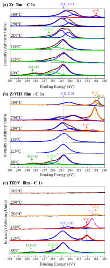
Figure 1.
SRPES spectra of the C 1s core-level peaks of (a) Zr film, (b) ZrVHf film and (c) TiZrV film recorded after heating at various temperatures.
For the Zr film (Figure 1a) at temperatures of 300 °C, there was a chemical shift to a lower binding energy of 281.1 eV, typical for zirconium carbide [25]. This suggests that the surface carbon partly desorbs and is partly transformed to zirconium carbide.
For ZrVHf film (Figure 1b), the chemical shift to metal carbide appeared after heating at 200 °C, a temperature much lower than that of the Zr film. After heating at 200 °C, the C 1s spectra showed a detectable quantity of V–C at 282.2 eV [25] and Zr–C at 281.3 eV. After heating at 250 °C, the metal carbide peak shifted to a lower binding energy of 281.1 eV, typical for Zr–C, with still a possible small amount of V–C at 282.2 eV. After heating at 300 °C, the Zr–C peak partly shifted to 280.8 eV, typical for Hf–C [25]. The above shifting of the metal carbide peaks suggests that as the heating temperature increases from 200 °C to 300 °C, the transformation of metal-C bond follows the order of V–C, Zr–C, Hf–C.
For TiZrV film (Figure 1c), the chemical shift from adventitious carbon to metal carbide at 282.1 eV, typical for V–C, appeared at temperatures as low as 120 °C. After heating at 180 °C, the intensity of carbon peak reduced and the V–C peak shifted to 281.5 eV, typical for Ti–C [25], suggesting that the surface carbon desorbs and vanadium carbide is transformed to titanium carbide. After heating at 200 °C, the surface carbon peak disappeared, and the carbide peak shifted to 281.1 eV, typical for Zr–C. After heating at temperatures above 250 °C, the Zr–C peak disappeared. The above shifting of the metal carbide peaks suggests that as the heating temperature increases from 120 °C to 200 °C, the transformation of metal-C bond follows the order of V–C, Ti–C, Zr–C. After heating at temperatures above 250 °C, the carbon bonded to zirconium diffused from the surface into the bulk [26].
Figure 2 shows SRPES spectra of the O 1s core-level peak of different NEG films recorded after heating at various temperatures. The deconvolution of O 1 s spectra resulted in the observation of O–C bond at 533.2 eV, -OH bond at 532.0 eV and lattice-O bonds ranging from 531.0 eV to 530.0 eV [27].
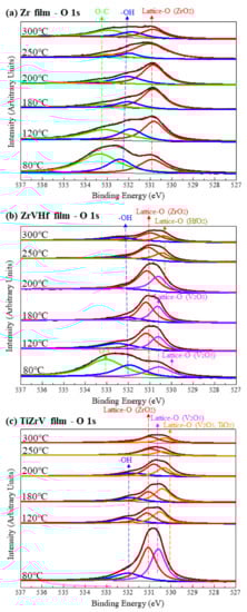
Figure 2.
SRPES spectra of the O 1s core-level peaks of (a) Zr film, (b) ZrVHf film and (c) TiZrV film recorded after heating at various temperatures.
For Zr film (Figure 2a), as the heating temperature increased from 80 °C to 250 °C, the intensity of the O–C and -OH group gradually reduced. After heating at 300 °C, the intensity of the lattice-O peak at 531.0 eV corresponding to O in ZrO2 [28] partly reduced.
For the ZrVHf film (Figure 2b), the intensity of the O–C and -OH group almost fully reduced after heating at 180 °C. After heating at 80 °C, the lattice-O peak at 530.5 eV showed a mixture of ZrO2, V2O3, V2O5 and HfO2. After heating at 120 °C, V2O5 reduced to V2O3 at 530.7 eV [28], which can be cross validated by the V 2p spectrum of the ZrVHf film mentioned later. After heating at 200 °C, the lattice-O peak started to shift to a lower binding energy, suggesting the reduction in V–O. After heating at 250 °C, the lattice-O peak had two components—ZrO2 at 531.0 eV and HfO2 at 530.4 eV [28]. The intensity of the ZrO2 and HfO2 components is partly reduced after heating at 300 °C. The shifting of the lattice-O peaks suggests that the ease of breaking the metal-O bond follows the order of V–O, Zr–O, Hf–O. After heating at temperatures above 250 °C, most O was bonded to Zr and Hf.
For TiZrV film (Figure 2c), after heating at 80 °C, metal-O bonds showed components of V2O5/TiO2 at 530.0 eV, V2O3 at 530.7 eV and ZrO2 at 531.0 eV [28]. The intensity of all components of the O 1s peak was significantly reduced at only 120 °C, suggesting that 120 °C may be the activation temperature for the TiZrV film. After heating at 300 °C, the intensity of the lattice-O was significantly reduced.
Figure 3 shows the SRPES spectra of the Zr 3d core-level peak of different NEG films recorded after heating at various temperatures. In all these cases, the deconvolution of Zr 3d spectra resulted in two peaks which corresponded to the Zr 3d5/2 and Zr 3d3/2, respectively.
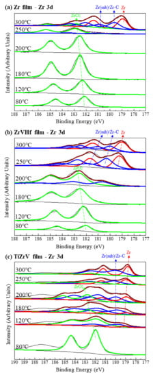
Figure 3.
SRPES spectra of the Zr 3d core-level peaks of (a) Zr film, (b) ZrVHf film and (c) TiZrV film recorded after heating at various temperatures.
In Figure 3a, for the 80 °C degassed Zr film, the binding energy of the Zr 3d5/2 is 182.2 eV, a value that corresponds to fully oxidized Zr (IV) [29]. After heating at 250 °C, the peak intensity of Zr (IV) significantly reduced, with a possible amount of Zr (sub) [30]. At high temperatures of 300 °C, the Zr (IV) peak shifted to a lower binding energy and consisted of several elementary peaks, with the majority corresponding to metallic Zr (0) at 178.8 eV [29], suggesting that Zr (IV) reduced to a large extent.
Compared to the Zr film, the reduction in Zr (IV) in the ZrVHf film occurred at a lower temperature of 200 °C, as can be seen in Figure 3b. Furthermore, in the TiZrV film as shown in Figure 3c, the Zr (IV) was partly reduced to Zr (sub) and Zr (0) after heating at a temperature as low as 120 °C. The tail at the binding energy of 187.4 eV is attributed to Auger peaks. It should be noted that since the binding energy of Zr–C is very close to that of ZrO (sub), the corresponding peaks could be a mixture of both.
Figure 4 shows SRPES spectra of the V 2p, Ti 2p and Hf 4f core-level peaks of ZrVHf and TiZrV films recorded after heating at various temperatures. The peak position resolved in Figure 4 is consistent with references [31,32,33]. In Figure 4a–c, the reduction in the fully oxidized states of V 2p and Ti 2p in ZrVHf and TiZrV films occurred after heating at a temperature of only 120 °C.
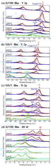
Figure 4.
(a) SRPES spectra of the V 2p core-level peak of ZrVHf film; (b) SRPES spectra of the V 2p core-level peak of TiZrV film; (c) SRPES spectra of the Ti 2p core-level peak of TiZrV film; (d) SRPES spectra of the Hf 4f core-level peak of ZrVHf film. All were recorded after heating the films at various temperatures indicated in the figures.
The integrated peak areas can be used to determine the content ratios of different states to understand the activation process. In Figure 4a, at 120 °C, there is no V (0), but V (sub). In Figure 4b, at 120 °C, V (0) and V (sub) appear with the percentages of 68.7 at% and 31.3 at%, respectively. Therefore, the activation of V in TiZrV is easier than that in ZrVHf. Comparing Hf 4f spectrum in Figure 4d and Zr 3d spectrum in Figure 3b of the ZrVHf film, both Hf 4f and Zr 3d started to move to a lower binding energy at 200 °C. It should be noted that since the binding energy of carbide is very close to that of sub-oxide, the corresponding peaks could be a mixture of both. In Figure 4d at 200 °C, Hf (sub) and Hf (IV) appear with the percentages of 16.6 at% and 83.4 at%, respectively. In Figure 3b at 200 °C, Zr (sub) and Zr (IV) appear with the percentages of 29.9 at% and 70.1 at%, respectively. Therefore, the activation of Zr is easier than Hf.
4. Discussion
After heating the TiZrV film at 120 °C for 0.5 h, the metal states of Ti 2p, V 2p and Zr 3d appeared, the intensity of the O 1s peak significantly reduced and metal carbide states of C 1s emerged. Therefore, it is reliable to state that the activation temperature of the TiZrV film is 120 °C. This is the lowest activation temperature reported for TiZrV. In other words, the TiZrV film can be fully activated by heating at 120 °C for a longer time. In a similar manner, the activation temperature for Zr and ZrVHf films were found to be 300 °C and 200 °C. Comparing to reference [19] (TiZrV film activated at 120 °C for 0.5 h), and reference [14] (TiZrV film activated at 150 °C for 1 h), the reduction degree of the TiZrV film found in this work after heating at 120 °C for 0.5 h is to a higher extent.
In addition, there are three phenomena worth noting. The first phenomenon is that as the heating temperature increases, the transformation of metal-C bond follows the order of V–C, Ti–C, Zr–C, Hf–C. The first phenomenon is found for films containing the same element. The temperature required to break the Zr–O bond on Zr, ZrVHf and TiZrV films is about 300 °C, 200 °C and 120 °C, respectively, suggesting that the difficulty of the reduction of Zr oxide in different NEG films follows the order of Zr film > ZrVHf film > TiZrV film. By comparing the content ratios of the V(0), V(sub) and V(V) states on TiZrV and ZrVHf films, the activation of V in TiZrV film is easier than that in ZrVHf film. The third phenomenon is found in the activation of different elements in the same film. The elemental carbon absorbed on the surface of the Zr, ZrVHf and TiZrV films started to transform to metal carbide phase after heating at 300 °C, 200 °C and 120 °C, respectively. On TiZrV film, the metal carbide phase was fully removed after heating at 250 °C or above. This confirmed the reported order of stabilities of the metallic oxides as follows: ZrO2 > TiO2 > V2O5 [34]. Combining the comparison of content ratios of Hf (sub)/Hf (IV) to Zr (sub)/Zr (IV) on ZrVHf film after heating 200 °C, the complete difficulty of the reduction of oxides follows the order of HfO2 > ZrO2 > TiO2 > V2O5.
The above phenomena can be explained by the thermodynamics of materials. The ZrVHf and TiZrV alloy films are substitutional solid solutions. The atomic radii of Ti, Zr, V and Hf elements are 176 pm, 206 pm, 171 pm and 208 pm, respectively. The electronegativities of Ti, Zr, V and Hf elements are 1.38, 1.32, 1.53, 1.16, respectively. Since they possess similar crystal structures, their atomic radius difference is within 15% and their electronegativities are similar, the solid solutions have high solubility. For NEG elements, at a typical temperature of activation, the free energy of formation of the oxide is larger than that of the solid solution per oxygen/carbon atom, so the solid solution phase is favored, that is, during activation, O and C diffuse into the bulk of the films. As the electronegativities of H, C, O are much higher and their atomic radii are much smaller, they diffuse in NEG crystals by interstitial diffusion. The overall diffusion coefficient of H, C, O in single crystals follows the order of V > Ti > Zr > Hf [8]. The difficulty of the reduction can also be explained by analysis of Gibbs free energy of the formation of oxides: in which and is the enthalpy difference and Gibbs free energy of reaction at 298 K as a reference [35]. The order of the stability of these metal oxides is HfO2 > ZrO2 > TiO2 > V2O5.
The alloy films prepared by sputtering are nanocrystalline or even amorphous. The grain size (<100 nm) can be calculated by the Scherrer formula: , where D is the average grain size, is the scattering angle, is the wavelength of X-ray (0.15406 nm), is the half height and width of the diffraction peak, and K is the Scherrer constant (0.89). The grain sizes of the Zr, ZrVHf and TiZrV films were measured and calculated to be 17, 23 , 133 , respectively. In addition to the interstitial diffusion, grain boundary diffusion (including free surface diffusion) plays an important role in the reduction of the alloy NEG film. Since there are many defects (holes, impurity atoms and dislocations) at the grain boundary, and the atoms at the grain boundary deviate from the equilibrium, and hence, have higher energy, the diffusion coefficient at the grain boundary is generally greater than that in the bulk. At room temperature, the irregular arrangement of the atoms at the grain boundaries will hinder the movement of dislocations, resulting in high strength and hardness [36] of the NEG films at macroscopic scale. The grain boundary is like a short-circuit for the residual gas atoms to diffuse much easier at a lower activation temperature. Since Ti, Zr and Hf are hexagonally close-packed (hcp) and V is body-centered-cubic (bcc), V cannot form an infinite solution with Zr, V and Hf. This difference is aggravated during the film growth process and heating treatment, resulting in the precipitation of V at the grain boundaries. The content of V and Ti is relatively higher at grain boundaries, while the content of Zr and Hf is relatively higher in the bulk [37]. The V and Ti precipitates protect Zr and Hf from oxidation to a certain extent. Consequently, the break of the Zr–O bond is easier at a relatively lower temperature in the TiZrV films.
5. Conclusions
The Zr, ZrVHf and TiZrV NEG films were prepared by DC magnetron sputtering. The activation process of the NEG films was investigated by in situ SRPES after heating at 80 °C for 6 h, and 120, 180, 200, 250 and 300 °C for 0.5 h, respectively, under UHV conditions.
From the emergence of the metal states and the change in O 1s and C 1s bonds, the activation temperature for the TiZrV film was found to be 120 °C—the lowest activation temperature ever reported on TiZrV. The activation temperature for Zr and ZrVHf films were 300 °C and 200 °C. The Zr, ZrVHf and TiZrV NEG films were able to be fully activated after the heating treatment at 300 °C, 200 °C and 120 °C, respectively, for a longer time.
There were three noteworthy phenomena: (1) as the heating temperature increased, the transformation of the metal-C bond followed the order of V–C, Ti–C, Zr–C, Hf–C; (2) in this work, it was found that for different NEG films containing the same elements, the order for reduction difficulty of the same element oxides, Zr oxide and V oxide in different films, followed Zr film > ZrVHf film > TiZrV film; and (3) it was also found that the order of difficulty in the reduction of Ti, Zr, V and Hf oxides in the same alloy NEG film followed HfO2 > ZrO2 > TiO2 > V2O5.
We propose that the above phenomena can be explained by thermodynamics of a solid solution. The overall diffusion coefficient of the residual gas atoms in single crystals follows the order of V > Ti > Zr > Hf. Since the alloy films prepared by sputtering is nanocrystalline or even amorphous, grain boundary diffusion plays a decisive role in the reduction. Due to the crystal structure difference, V cannot form an infinite solution with Zr, V and Hf. During the film growth process and heating treatment, V and Ti tend to precipitate more at the grain boundaries. The V and Ti precipitates act as a protection layer for Zr and Hf in the bulk. Consequently, the reduction of ZrO2 is easier at relatively lower temperature in TiZrV films. At a similar grain size, TiZrV has a lower activation temperature than ZrVHf. TiZrV is suitable for applications requiring a low operating temperature.
Author Contributions
Conceptualization, Y.Y. and P.H.; methodology, T.H. and Y.M.; software, Y.Y. and S.C.; validation, J.W.; formal analysis, Y.Y.; investigation, Y.Y., Z.C. and X.P.; resources, F.S.; data curation, Y.Y., B.L. and X.W.; writing—original draft preparation, Y.Y.; writing—review and editing, Y.Y. and J.W.; visualization, Y.Y.; supervision, H.D.; project administration, P.H.; funding acquisition, P.H. and H.D. All authors have read and agreed to the published version of the manuscript.
Funding
This work is supported by High Energy Photon Source (HEPS), a major national science and technology infrastructure.
Institutional Review Board Statement
Not applicable.
Informed Consent Statement
Not applicable.
Data Availability Statement
The data presented in this study are available on request from the corresponding author.
Conflicts of Interest
The authors declare no conflict of interest. The funders had no role in the design of the study; in the collection, analyses, or interpretation of data; in the writing of the manuscript, or in the decision to publish the results.
References
- Benvenuti, C.; Chiggiato, P.; Cicoira, F.; Ruzinov, V. Decreasing surface outgassing by thin film getter coatings. Vacuum 1998, 50, 57–63. [Google Scholar] [CrossRef]
- Li, Y.; Liu, X. Vacuum Science and Technology for Particle Accelerator; USPAS Vacuum Albuquerque: Albuquerque, NM, USA, 17–21 June 2019. [Google Scholar]
- Santucci, A.; Farina, L.; Tosti, S.; Frattolillo, A. Novel non-evaporable getter materials and their possible use in fusion ap-plication for tritium recovery. Molecules 2020, 25, 5675. [Google Scholar] [CrossRef]
- Lin, S.; Huang, X.; Gu, D.; Lv, W.; Wang, L. Investigation on Nickel-Based Nano-Scaffold Getter With Induction Heating and Rapid Activation. IEEE Trans. Nanotechnol. 2019, 19, 67–70. [Google Scholar] [CrossRef]
- Wang, J.; Gao, Y.; You, Z.; Fan, J.; Zhang, J.; Yang, S.; Guo, S.; Wang, S.; Xu, Z. Laser Processed Oxygen-Free High-Conductivity Copper with Ti and Ti–Zr–V–Hf Films Applied in Neutron Tube. Appl. Sci. 2019, 9, 4940. [Google Scholar] [CrossRef]
- Chuntonov, K.; Setina, J.; Douglass, G. The Newest Getter Technologies: Materials, Processes, Equipment. J. Mater. Sci. Chem. Eng. 2015, 3, 57–67. [Google Scholar] [CrossRef][Green Version]
- Benvenuti, C.; Chiggiato, P.; Pinto, P.C.; Santana, A.E.; Hedley, T.; Mongelluzzo, A.; Ruzinov, V.; Wevers, I. Vacuum properties of TiZrV non-evaporable getter films. Vacuum 2001, 60, 57–65. [Google Scholar] [CrossRef]
- Prodromides, A.; Scheuerlein, C.; Taborelli, M. Lowering the activation temperature of TiZrV non-evaporable getter films. Vacuum 2001, 60, 35–41. [Google Scholar] [CrossRef]
- Ferreira, M.; Seraphim, R.; Ramirez, A.; Tabacniks, M.; Nascente, P. Characterization and Evaluation of Ti-Zr-V Non-evaporable Getter Films Used in Vacuum Systems. Phys. Procedia 2012, 32, 840–852. [Google Scholar] [CrossRef]
- Wu, M.; Moulin, J.; Coste, P.; Perrot, S.; Perrossier, J.-L.; Renard, C.; Bosseboeuf, A. Comparative study of Au/Ti, Au/V and Au/Zr films oxygen gettering ability. Thin Solid Films 2016, 616, 543–549. [Google Scholar] [CrossRef]
- Malyshev, O.B.; Valizadeh, R.; Hannah, A.N. Pumping and electron-stimulated desorption properties of a dual-layer nonevaporable getter. J. Vac. Sci. Technol. A 2016, 34, 061602. [Google Scholar] [CrossRef]
- Wang, J.; Zhang, J.; Gao, Y.; Hu, Y.; You, Z.; Xie, Y.; Li, H.; Wu, Y.; Yang, S.; Wang, D.; et al. The Activation of Ti-Zr-V-Hf Non-Evaporable Getter Films with Open-Cell Copper Metal Foam Substrates. Materials 2020, 13, 4650. [Google Scholar] [CrossRef] [PubMed]
- Bibienne, T.; Gosselin, C.; Bobet, J.-L.; Huot, J. Replacement of Vanadium by Ferrovanadium in a Ti-Based Body Centred Cubic (BCC) Alloy: Towards a Low-Cost Hydrogen Storage Material. Appl. Sci. 2018, 8, 1151. [Google Scholar] [CrossRef]
- Wang, S.; Wang, Z.; Shu, X.; Wei, W.; Gao, Y.; Wang, Y. Activation characterization of the Ti-Zr-V getter films deposited by magnetron sputtering. Appl. Surf. Sci. 2020, 528, 147059. [Google Scholar] [CrossRef]
- Bansod, T.; Sindal, B.K.; Kumar, K.V.A.N.P.S.; Shukla, S.K. Evaluation of Ti-Zr-V (NEG) Thin Films for their pumping speed and pumping Capacity. J. Phys. Conf. Ser. 2012, 390, 012023. [Google Scholar] [CrossRef]
- Chiggiato, P.; Pinto, P.C. Ti–Zr–V non-evaporable getter films: From development to large scale production for the Large Hadron Collider. Thin Solid Films 2006, 515, 382–388. [Google Scholar] [CrossRef]
- Šutara, F.; Matolínová, I.; Skála, T.; Masek, K.; Matolin, V. Residual surface oxide on ZrV getter—XPS, LEIS and SIMS study. Vacuum 2004, 74, 305–309. [Google Scholar] [CrossRef]
- Li, C.C.; Huang, J.L.; Lin, R.J.; Chen, C.H.; Lii, D.F. Characterization of activated non-evaporable porous Ti and Ti–Zr–V getter films by synchrotron radiation photoemission spectroscopy. Thin Solid Films 2006, 515, 1121. [Google Scholar] [CrossRef]
- Li, C.-C.; Huang, J.-L.; Lin, R.-J.; Lii, D.-F.; Chen, C.-H. Activation characterization of non-evaporable Ti–Zr–V getter films by synchrotron radiation photoemission spectroscopy. Thin Solid Films 2009, 517, 5876–5880. [Google Scholar] [CrossRef]
- Scheuerlein, C.; Taborelli, M. Electron stimulated carbon adsorption in ultrahigh vacuum monitored by Auger electron spectroscopy. J. Vac. Sci. Technol. A 2002, 20, 93–101. [Google Scholar] [CrossRef][Green Version]
- Ge, X.; Wang, Y.; Shao, J.; Wei, W.; Zhang, B.; Wang, S.; Zhang, Y.; Li, W.; Wang, Y. Testing the activation temperature of non-evaporable Ti-Zr-Hf-V getter films by XPS. Nuclear Inst. Methods Phys. Res. A 2020, 967, 163864. [Google Scholar] [CrossRef]
- Henrist, B.; Hilleret, N.; Scheuerlein, C.; Taborelli, M. The secondary electron yield of TiZr and TiZrV non-evaporable getter thin film coatings. Appl. Surf. Sci. 2001, 172, 95–102. [Google Scholar] [CrossRef]
- Prodromides, A. Non-Evaporable Getter Thin Film Coatings for Vacuum Applications. Ph.D. Thesis, Ecole Polytechnique Federale de Lausanne, Lausanne, Switzerland, 2002. No. 2652. [Google Scholar]
- Barr, T.L.; Seal, S. Nature of the use of adventitious carbon as a binding energy standard. J. Vac. Sci. Technol. A 1995, 13, 1239–1246. [Google Scholar] [CrossRef]
- Ramqvist, L.; Hamrin, K.; Johansson, G.; Fahlman, A.; Nordling, C. Charge transfer in transition metal carbides and related compounds studied by ESCA. J. Phys. Chem. Solids 1969, 30, 1835. [Google Scholar] [CrossRef]
- Fabik, S.; Chab, V.; Dudr, V.; Masek, K.; Prince, K.C.; Sutara, F.; Veltruska, K.; Tsud, N.; Vondracek, M.; Matolin, V. Activa-tion of binary Zr-V non-evaporable getters: A soft X-ray photoemission study of carbide formation. Surf. Sci. 2004, 566–568, 1246–1249. [Google Scholar] [CrossRef]
- Barreca, D.; Battiston, G.A.; Gerbasi, R.; Tondello, E.; Zanella, P. Zirconium dioxide thin films characterized by XPS. Surf. Sci. Spectra 2000, 7, 303. [Google Scholar] [CrossRef]
- Noda, H.; Oikawa, K.; Ogata, T.; Matsuki, K.; Kamada, H. Preparation of Titanium (IV) Oxides and Its Characterization. ChemInform 1986, 8, 1084. [Google Scholar]
- Moulder, J.F.; Stickle, W.F.; Sobol, P.E.; Bomben, K.D. Bomben Handbook of X-ray Photoelectron Spectroscopy; Perkin-Elmer Corporation Physical Electronics Division: Eden Prairie, MN, USA, 1992; p. 40. [Google Scholar]
- Petti, D.; Cantoni, M.; Leone, M.; Bertacco, R.; Rizzi, E. Activation of Zr–Co–rare earth getter films: An XPS study. Appl. Surf. Sci. 2010, 256, 6291–6296. [Google Scholar] [CrossRef]
- Biesinger, M.C.; Lau, L.W.; Gerson, A.R.; Smart, R.S.C. Resolving surface chemical states in XPS analysis of first row transi-tion metals, oxides and hydroxides: Sc, Ti, V, Cu and Zn. Appl. Surf. Sci. 2010, 257, 887–898. [Google Scholar] [CrossRef]
- Wu, L.-H.; Lin, T.-C.; Cheng, C.-M.; Chang, C.-C.; Chan, C.-K.; Perng, S.-Y.; Sheng, I.-C. Comparative study of Ar-implanted Ti-Zr-V non-evaporable getter films on the Al-alloy substrate. AIP Adv. 2018, 8, 075025. [Google Scholar] [CrossRef]
- Hernández-Arriaga, H.; López-Luna, E.; Martínez-Guerra, E.; Turrubiartes, M.M.; Rodríguez, A.G.; Vidal, M.A. Growth of HfO2/TiO2 nanolaminates by atomic layer deposition and HfO2-TiO2 by atomic partial layer deposition. J. Appl. Phys. 2017, 121, 064302. [Google Scholar] [CrossRef]
- Jeffes, J.H.E. Ellingham Diagrams. In Encyclopedia of Materials: Science and Technology; Buschow, K.H.J., Cahn, R.W., Flemings, M.C., Ilschner, B., Kramer, E.J., Mahajan, S., Veyssière, P., Eds.; Elsevier: Oxford, UK, 2001; pp. 2751–2753. [Google Scholar]
- Haynes, W.M. Handbook of Chemistry and Physics, 94th ed.; CRC Press: Boca Raton, FL, USA, 2013; ISBN 9781466571143. [Google Scholar]
- Lee, T. Variation in Mechanical Properties of Ti-13Nb-13Zr Depending on Annealing Temperature. Appl. Sci. 2020, 10, 7896. [Google Scholar] [CrossRef]
- Ping, T. The Microstructure and Hydrogen Storage Property of NbTiZrV(Hf) Alloys. Ph.D. Thesis, Harbin Institute of Technology, Harbin, China, June 2015. [Google Scholar]


Publisher’s Note: MDPI stays neutral with regard to jurisdictional claims in published maps and institutional affiliations. |
© 2021 by the authors. Licensee MDPI, Basel, Switzerland. This article is an open access article distributed under the terms and conditions of the Creative Commons Attribution (CC BY) license (https://creativecommons.org/licenses/by/4.0/).