Article

Simulated Annealing for Resource Allocation in Downlink NOMA Systems in 5G Networks

by
Osama Abuajwa
,
Mardeni Bin Roslee
* and
Zubaida Binti Yusoff
Faculty of Engineering, Multimedia University, Cyberjaya 63100, Malaysia
*
Author to whom correspondence should be addressed.
Appl. Sci. 2021, 11(10), 4592; https://doi.org/10.3390/app11104592
Submission received: 9 April 2021 / Revised: 12 May 2021 / Accepted: 14 May 2021 / Published: 18 May 2021
(This article belongs to the Special Issue 5G Network Planning and Design)

Abstract

:
In this work, we investigate resource allocation and user pairing to improve the system’s Throughput for the downlink non-orthogonal multiple access (NOMA)-based 5G networks. The proposed resource allocation involves user pairing, subchannel power allocation, and proportional power allocation among the multiplexed users. The resource allocation is a non-deterministic polynomial (NP-hard) problem that is difficult to tackle throughput maximization. The user pairing and power allocation are coupled to address the substantial requirements of the NOMA system. The NOMA system requires an efficient deployment of resource allocation techniques to enhance the system’s throughput performance. In this work, we propose simulated annealing (SA) to optimize the power allocation and perform user pairing to maximize the throughput for the NOMA system. Also, we provide mathematical proof on the near-optimal solution for subchannel power and mathematical analysis on the optimal value of the power ratio for the multiplexed users in the NOMA system. The SA provides a significant throughput performance that increases by 7% compared to the existing numerical optimization methods. Results obtained show that SA performs with sufficient reliability and low time complexity in terms of Throughput improvement.

1. Introduction

1.1. Preliminaries

In wireless communication, each generation from 1st generation (1G), 2nd generation (2G), 3rd generation (3G), 4th generation (4G), and 5th generation (5G) is required to adopt different multiple access techniques to satisfy the system capacity and data traffic demand. The ever-increasing demand on data traffic for mobile users, while exacerbating the challenges of the spectrum and resource allocation problem in the 5G networks [1,2,3]. 5G networks require a technology that can meet this massive connectivity, high data rate, and high spectral efficiency demand. In previous network generations, the traditional orthogonal multiple access (OMA) can serve multiple users using the available orthogonal resources. These orthogonal resources are restricting the number of users employed in the system. Thus, OMA is an inadequate system to satisfy the requirements of the 5G network. Currently, non-orthogonal multiple access (NOMA) has been developed to overcome the inadequacy of OMA to meet 5G network requirements. NOMA is a promising technique, where multiple users can share the frequency, code, or time with different power levels in NOMA power domain multiplexing. Hence, NOMA technologies apply signal interference cancellation (SIC) at one of the receiving ends to mitigate the multiplexed users’ interference. NOMA technologies have enormous potential advantages in providing low latency, supporting more devices, allowing massive connectivity, and providing better throughput fairness [4].
The NOMA’s full potential requires an optimal resource allocation such as user pairing, channel power allocation, and sufficient power for each multiplexed user on the same channel. Furthermore, an overview of the literature related to the resource allocation schemes in NOMA is presented in the subsection.

1.2. Related Work

The resource allocation schemes involve user pairing and power allocation as an interactive approach to improving NOMA performance. The literature is reviewed to examine the available user pairing and power allocation approaches as tabulated in Table 1. The summary of the investigated methods is discussed based on the objectives and the proposed methods for resource allocation in the NOMA system.
The authors in [5] proposed a closed-form solution for power allocation scheme under conditions of the Karush-Kuhn-Tucker (KKT) condition for single-input single-output (SISO) and multiple-input multiple-output (MIMO) in downlink NOMA. Similarly, the closed-form solution is derived for optimal power using KKT condition for sum-rate maximization in the NOMA system with imperfect channel state information (CSI) transmitter [6]. Sun. et al. [7] proposed an optimal power allocation solution using a bisection search algorithm with high computational complexity for ergodic capacity maximization under statistical channel state information (CSI) for the MIMO NOMA system. The authors in [8] have proposed a user selection approach based on an exhaustive search and power allocation method using the minimum mean square error (MMSE) to maximize the weighted sum rate of a downlink NOMA system. Further, the optimal solution is found by employing the KKT condition for the power allocation problem. Parida [9] proposed user and channel matching and iterative power allocation scheme to maximize the total sum-rate for orthogonal frequency-division multiple-access (OFDM) based NOMA. The optimization problem in [9] is divided into subproblems, where greedy users and channel matching are employed based on heuristic solutions. Then the difference of convex (DC) programming is used to obtain the suboptimal power for each subchannel and power ratio between the multiplexed users.
The authors in [10] proposed subchannel matching for user and subchannel assignment and DC to determine the subchannel and user’s power to improve the NOMA network’s Throughput and energy efficiency. The DC achieved a suboptimal solution for power allocation, also outperforming the OFDMA scheme. Wang et al. [11] proposed a joint allocation scheme based on simulated annealing (SA) for subcarrier assignment and DC for power allocation to maximize the throughput for the NOMA-enhanced relay network. The joint resource allocation is divided into two subproblems to reduce the coupled resources’ complexity between the subcarrier and power allocation. The SA is used for the subcarrier assignment with fixed power, then replaces the fixed power with the power obtained DC-based Lagrangian dual method to optimize the power allocation.
The authors in [12] proposed an optimal transmission power for each user by deriving two closed-form suboptimal solutions using the Lagrange multiplier to maximize the NOMA’s system total sum rate. In terms of complexity, the work initially derived the suboptimal power for two-user configuration and was then extended for multi-user by subbands transmission using bandwidth division.
Choi et al. [13] proposed a proportional fairness scheduling (PFS) approach to achieving optimal power allocation and maximize the sum-rate under the minimum rate constraint for downlink NOMA with two users. The PFS scheme maximized the minimum rate with a 0.1% variation of the transmission rate. The authors in [14] proposed a power allocation scheme based on the iterative fractional quadratic transformation to solve the non-convexity complexity and employed user scheduling to maximize the weighted sum-rate (WSR) while considering imperfect SIC in multi-carrier NOMA (MC-NOMA) system.
Ahmed et al. [15] proposed generalized power allocation (GPA) to calculate the different power for many users with no requirement to adjust any of the NOMA parameters based on the wireless communication system. The proposed power allocation scheme showed a slight variation percentage than the arbitrary power allocation and performed with similar behavior as the conventional power allocation for the NOMA system.
The authors in [16] investigated user pairing schemes by testing the channel gain difference of the two users in the case of NOMA while allocating fixed power (F-NOMA) and another NOMA inspired by cognitive radio (CR-NOMA). The F-NOMA has shown a large Throughput that is better than the conventional OMA scheme where the user pairing is performed based on the two users experiencing good channel conditions. In CR-NOMA, the users with the best channel gain are paired with the second-best channel gain user, while the F-NOMA paired that user with the lowest channel gain. Thus, CR-NOMA showed different behavior than F-NOMA, but F-NOMA outperformed CR-NOMA because of the constraints on transmit power allocated to other users in the CR-NOMA.
Bao. et al. [17] proposed a joint optimization scheme to maximize throughput in the NOMA system by the Lyapunov optimization framework that converted the original long-term optimization problem into a series of online rate controls in the network layer and power allocation problems in each time slot in the physical layer. The work also obtained the optimal global solution with a polynomial computational complexity using a power allocation algorithm based on dynamic programming and it explored the two optimal solutions.
The authors in [18] proposed a near-optimal solution using a two-sided matching scheme by combining the power allocation and maximum fairness (MMF) to improve throughput for the NOMA system. The proposed joint optimal resource allocation scheme is used iteratively to refine the solution. Al-Abbasi et al. [19] proposed hybrid multiple access schemes that combined the properties of NOMA and OFDMA for sum-rate maximization under constraints of total power and the proportional rate of the NOMA system. The suboptimal solution is obtained for two users, and the work is extended to serve the multiuser using a hierarchical pairing power allocation (HPPA) process in the NOMA system.
The authors in [20] proposed a projected gradient descent algorithm as a centralized power allocation method for a fixed subcarrier assignment, along with a greedy heuristic search for the user and subchannel matching to maximize the sum rate for MC-NOMA. The achieved solution is near-optimal with lower computational complexity than other near-optimal solutions. In [21], we proposed a power allocation scheme with two user configurations using the ant colony optimization (ACO) method to optimize the subchannel power and the power ratio among the multiplexed users. The proposed method is developed for a system with two users, and bandwidth division is adopted to extend the work to serve a larger number of users in the network. Therefore, the NOMA potentially enables the users to access the entire bandwidth, where the bandwidth division cannot meet that concept.
Resource allocation is defined as a non-convex problem [9,14,17], where the direct numerical method is not efficient in solving it. A method is required to transform the non-convex problem into a convex problem in order to achieve an effective solution. However, no tractable solutions can be guaranteed for a non-convex optimization problem by converting it into a sub-problem. Furthermore, the optimal solution obtained by changing the non-convex into the convex may not be the optimal solution but can be the approximate solution. Most numerical optimization algorithms can only optimize the power allocation while requiring a user pairing scheme to achieve a comparable optimal resource allocation solution. Therefore, the optimal resource allocation can only be achieved in parallel with the optimal user pairing scheme.
Simulated annealing (SA) is one of the metaheuristic optimization algorithms that work dynamically and iteratively to obtain the optimal solution, which can be more realistic and reliable in solving a non-convex optimization problem. The SA algorithm mimics the physical annealing process where it puts the material under a high temperature, then reduces the temperature slowly until a crystalline state is formed with the minimum energy and larger crystal size. The SA starts from a melting phase based on the physical crystal form, then the temperature of the molten crystal is reduced very slowly until the structure of the crystal is formed and stabilized without any defects [22]. The SA algorithm can find the global solution fast and guarantees a convergence upon running enough iterations. This is a significant advantage of the SA, while the gradient descent algorithm obtains the local solution. Moreover, SA is applied to both combinatorial and continuous optimization problems.
The NOMA system’s resource allocation challenge can be designed and modeled using SA since tuning the parameters is relatively controllable. In NOMA system-based power domain multiplexing, multiple users share the same radio resources, requiring an optimal resource allocation. Heretofore, no literature has reported applying SA to the issues related to resource allocation in the NOMA system. The SA algorithm is used to solve the user pairing and power allocation to maximize the total Throughput in the NOMA system. Moreover, SA is developed to determine the subchannel power and the power ratio for the multiplexed users, where the channel difference is the primary criteria to form the users and subchannels matching scheme. The user pairing scheme is designed using the two types of channel gain difference as a hot and cold configuration that ensures optimal user and subchannel matching.
In this work, we propose a novel resource allocation scheme to maximize the Throughput for the downlink 5G NOMA system using SA. We also provide mathematical proof that equal power allocation can be the near-optimal solution for the NOMA system’s subchannel power allocation problem. Further, we mathematically prove that the proportional power ratio can be fixed to a value between 0 to 1 that can maximize the Throughput based on the NOMA concept. The remainder of the paper is organized as follows. Section 2 presents the downlink NOMA system model and the mathematical formulation of the resource allocation optimization problem. In Section 3, we provide full detail of the proposed method used for resource allocation. The system model parameters and the analysis of the results are presented in Section 4. Finally, the work conclusion is drawn in Section 5.

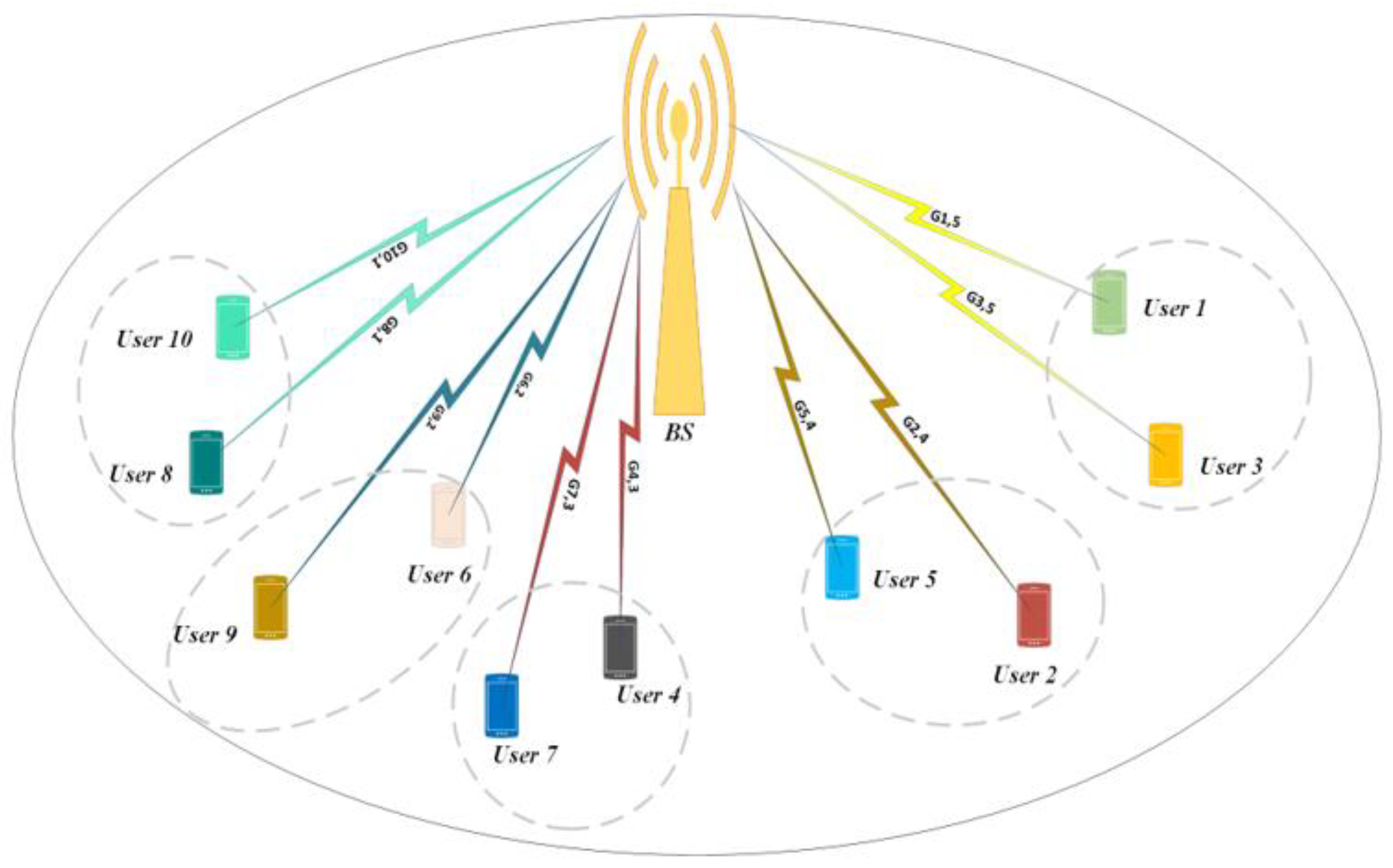
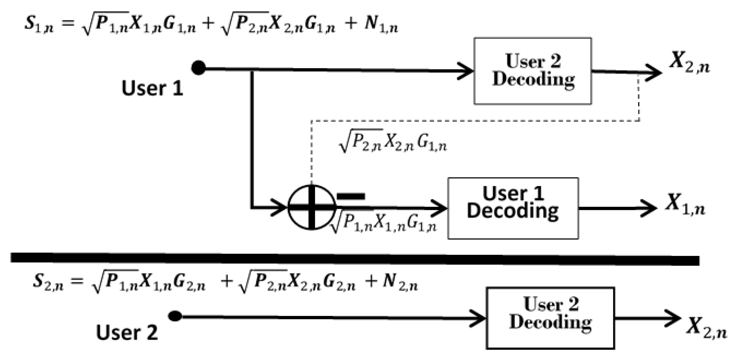
2. NOMA System Model

In this work, we design the downlink NOMA system as a SISO scenario equipped with BS at the cell’s center with a uniform distribution of U total number of users. The BS serves multiple users at the same time, code, or frequency with different power levels according to the NOMA-based 5G system. The NOMA power domain multiplexing scheme is the standard NOMA system that offers the fundamental concept of multiplexing two users on the same channel by allocating different power levels. Figure 1 illustrates the concept of the downlink NOMA system with 10 users.
The system run with a total bandwidth B t o t a l that is equally allocated among the subchannels where the subchannel bandwidth B s c = B W t o t a l / N s c . The BS serves a total U number of users that receive their signals through a total number of subchannels N s c . In the system, we use u as index of u t h users where u { 1 , 2 , ... , U } and n as index of n t h subchannel where n { 1 , 2 , ... , N s c } . In this system, we assume that only two users are multiplexed on the same subchannel. The system employs superposition coding for the multiplexed users, where the design considers U n { U 1 , U 2 , ... , U N s c } is the number of users multiplexed on the same n t h subchannel and U i , n denotes the i t h user on the subchannel n . The BS transmits a signal carrying a superposition coded symbol on the intended subchannel n as shown below:
x n = i = 1 U n p i , n x ¨ i
where x ¨ i is the transmitted symbol of i t h user on the subchannel n and the power allocated to i t h user is p i , n . The total allocated power to the subchannel n is P n where i = 1 U n P i , n = P n , while if ith user is not assigned to subchannel n , then the p i , n = 0 . The received signal at m t h user on subchannel n is given as follows:
S m , n = g m , n x n + N m , n = P m , n g m , n x m + i = 1 , i m U n p i , n   g m , n   x i + Z m , n
where g m , n is the coefficient between the base station and the desired user U n on subchannel n , where g m , n = h m , n / ( d ) . The ( d ) is the function of the path loss at a distance (d) between the BS and U m , n with Rayleigh fading channel gain as h m , n . The additive Gaussian white noise (AWGN) is denoted as Z m , n with zero mean and σ 2 variance, where Z m , n ~ C N ( 0 , σ 2 ) . The variance is σ 2 = ( B W t o t a l / N s c ) N ° , where N ° is the power spectral density. Each user receives a mixed signal, where the successful reception of the user’s message is guaranteed by separating the received user’s messages. Since the BS send a superimposed message signal on the same subchannel for the multiplexed users, the co-channel interference is an active phenomenon in NOMA.
The successive interference cancellation (SIC) is adopted to solve the interference phenomena in NOMA. The received signal-to-interference-plus-noise ratio (SINR) without SIC of the m t h user on subchannel n is given below:
S I N R m , n = P m , n   g m , n σ n 2 + i = 1 , i m U n P i , n   g m , n = P m , n   G m , n   1 + i = 1 , i m U n P i , n G m , n  
where G m , n is the channel response normalized by noise (CRNN) of m t h on S C n that represented as G m , n | g m , n | 2 / σ n 2 , where σ n 2 = Ε | N m , n | 2 the noise power on subchannel n . According to Shannon’s capacity formula, the throughput of subchannel n is given below:
R n = B s c   i = 1 U n log 2 ( 1 + P m , n   | G m , n | 2 1 + i = 1 , i m U n P i , n   G m , n ) = B s c   i = 1 U n log 2 ( 1 + S I N R m , n )
The user U m , n receives interference from the other user, where the interferences S I N R m , n , also denoted as γ m , n , are expressed as follows:
γ m , n = i = 1 , i m U n P i , n   G m , n
The NOMA’s basic principle is to perform SIC at one receiver to reduce the interference between the multiplexed users on the same subchannel. The SIC technique enables the user with stronger CRNNs to decode the user’s signal with poorer CRNNs and cancel it from the superimposed message. However, the user with the poorer CRNNs decodes the intended signal and treats the other signal as noise. Moreover, the increasing order of CRNNs achieves the optimal decoding order for appropriate SIC performance. Hence, any user can decode the other user’s signal successfully and correctly based on the CRNNs order.
In power domain multiplexing, the NOMA system allocates more power to the user with lower CRNN to maximize the throughput and achieve balanced Throughput between the multiplexed users. For instance, the two users U 1 , n and U 2 , n are multiplexed on the same subchannel n with | G 1 , n | 2 | G 2 , n |   2 , and the user fairness is ensured by the power allocation scheme of P 1 , n P 2 , n based on the NOMA power allocation protocol [4,23,24].
In Figure 2, SIC application is performed for each subchannel, where each user can extract the intended signal. Consider that the users allocated on the same subchannel n are U U n , n . The user multiplexing scheme is adopted based on CRNNs in order to assign users on the same subchannel as | G 1 , n | | G 2 , n | | G m , n | | G m + 1 , n | | G U n   ,   n | . The user U E m decodes and cancels the interference power from the user with a weaker channel condition as U E m + 1 .. U E m + 2 , , U E U n , according to the optimal SIC decoding order where the interference is cancelled successfully. However, during the decoding process user U E m experiences a weaker channel condition and will not be able to remove the interference from the user U E m 1 , who experiences better channel conditions, so it treats the interference power as noise. The standard NOMA design is assumed to allocate more power ratio to the user with a weak channel gain and less power ratio to the user with a strong channel gain. In the first step, SIC will decode the data signal of the user with a weak channel gain as more power is assigned. In the second step, the second data signal is decoded for the user with a strong channel gain, where the lower power ratio is assigned. The optimal SIC application depends on the power ratio for the multiplexed users, where the power level difference is the main factor in reducing the SIC complexity. Therefore, the user U m , n performs SIC, while SINR is expressed as follows:
S I N R m , n S I C = P m , n   G m , n   1 + i = 1 , i m m 1 P i , n G m , n  

Problem Formulation

The optimization problem is formulated for resource allocation. In mobile communication networks, the optimization aims to maximize the system’s capacity with minimum power allocation to achieve Throughput maximization. In the NOMA system, each subchannel is assigned by power P n , and the throughput over subchannel n is defined as R n . The total throughput is given as:
R T o t a l = n = 1 N s c R n
In the downlink NOMA system, only two users are multiplexed on the same subchannel to reduce the complexity of the SIC performance. In this system, two users share the same subchannel n while considering G 1 , n G 2 , n , and the throughput of the subchannel with respect to P n can be expressed in (8).
f ( P n ) = B s c 1 , n l o g 2 ( 1 + δ n P n G 1 , n ) + B s c 2 , n l o g 2 ( 1 + ( 1 δ n ) P n G 2 , n 1 + δ n P n G 2 , n )
where δ n is the proportional power factor for the two multiplexed users on subchannel n . In general, the δ n ( 0 , 1 ) and the user with high channel gain always performs SIC. The proposed user pairing scheme is deployed to ensure the optimality of the power allocation scheme and guarantee that more power is assigned to the second user who is experiencing weaker channel conditions. In the system, the throughput optimization problem is formulated as below:
max   P n > 0 n = 1 N s c m = 1 U n R m , n ( P m , n ) =   n = 1 N s c R n ( P n )
subject to:
C 1 : n = 1 N s c P n P M a x
C 2 : n = 1 N s c R m , n ( P n ) R M i n
The objective function is limited by the summation of the subchannels power not exceeding the maximum transmit power P M a x according to C 1 . Also, the minimum user’s throughput is ensured as a minimum target throughput in C 2 . The resource allocation in NOMA is considered a non-convex and NP-hard problem. Therefore, finding the global solution within the polynomial-time is a challenge. The subchannel, user assignment, and power allocation are separated to solve the coupled problem.

3. Simulated Annealing Based Resource Allocation

The simulated annealing algorithm is adopted to maximize the overall throughput for the downlink NOMA system. The SA algorithm allocates power for each subchannel and the proportional power for each multiplexed user on the same subchannel and assigns multiple users on the same subchannel. The SA algorithm imitates the physical annealing process by putting the metal into a high temperature with high energy, then reducing the heat to obtain the crystal structure with minimum energy [22]. The energy function in the physical annealing is defined as the throughput objective function in the proposed SA algorithm. The objective function is formulated to maximize the total throughput, as shown in (8). The algorithm evaluates the objective function based on the allocated power for each subchannel P n and the power ratio δ n among the multiplexed users, as well as the user and subchannel matching. The SA design defines the parameters a n = P n / P M a x , as a fraction of the total transmitted power P M a x . The δ n is the power ratio for the multiplexed users on the same subchannel, and the channel gain difference is the main factor for the user and subchannel matching scheme. The SA system started by assigning random channel power based on the factional value of a n , random value of power ratio δ n , and multiplexing two users randomly on the same subchannel. The initial design of the SA algorithm is considered as the current best solution for the objective function, then one parameter is changed according to the system mode. The SA algorithm accepted the solution after each change if the new solution is better than the current best solution, otherwise accepted with probability. The accepted new solution for each system mode is updated in the current best solution set, then the temperature is reduced and used for the next iteration temperature. The parameters are used to estimate throughput by changing one parameter every iteration while keeping the other two parameters fixed. This process can reduce the time complexity of re-calculating the objective function every iteration until the total throughput is achieved. The system initiates with two different configurations of user and subchannel matching. The change of one parameter every iteration can offer less computational time, and decouple the resource allocation problem since the problem is coupled. One parameter is changed in each iteration based on the system mode, and the mode is chosen according to the random value of μ . The user pairing is conducted when μ = 1 , the subchannel power is changed when μ = 2 , and the proportional power ratio is changed when μ = 3 . Moreover, SA is a flexible standalone algorithm that ensures an optimal solution for the coupled problem of resource allocation and user and subchannel matching. SA is a minimization algorithm, so we use a minus sign in the objective function. The SA algorithm is described in the three following subsection steps.

3.1. SA for User Pairing

The SA algorithm performed the user pairing scheme when the system mode μ = 1 . In this system, the SA algorithm started with two different configurations, such as hot and cold configurations, based on the channel’s gain difference. This considers that subchannels are accessible by all users. This assumption addresses the impact of the channel gain difference on the user pairing scheme and the throughput performance [16]. Furthermore, the user pairing scheme exploits the channel gain difference for the multiplexed users, which should be investigated to guarantee the minimum target data rate for the user with the weakest channel gain. The hot configuration started the initial design by randomly multiplexing the user with high channel gain with the user with low channel gain on the same subchannel as the current best solution. The cold configuration established the initial design by matching the users randomly based on descending order of channel gain on the same subchannel as a current best solution [16]. The users and subchannels matching scheme are performed in the cold configuration, enabling the search to start based on both users’ good channel gain conditions [16]. The average channel gain for each subchannel is employed in the cold configuration as calculated in (12):
G A v = i = 1 U G i , n U
where U is the total number of users accessing the particular subchannel and G i , n is the channel gain corresponding to the users.
Algorithm 1: Proposed SA Subchannel and User Matching Scheme.
  • Set the number of iterations j { 1 , 2 , .... , J M a x } , the initial temperature T = 100:
  • Initialize the users set and subchannel set.
  • Estimate the channel gain G   g ^ u , n U × N .
  • Initialize the U U n a s s i g n e d   and   N U n a s s i g n e d in the system.
  • Pair two users on the same subchannel according to Hot Config as current Best Solution C B
    Pair two users on the same subchannel according to Cold Config as current Best Solution C B   .
  • Calculate Throughput function of the Initial design f C B   :
  • System Mode If μ = 1 .
  • Choose two random subchannels 1 : N s c while fixing the initial values of a n   and   δ n .
  • Exchange the users with high channel gain for both selected subchannels.
  • Check if the Second selected subchannel is still giving high channel gain to the shifted user.
  • If yes; exchange the two users with high channel gain.
  • If no; check the user with low channel gain to exchange.
  • Check the low channel gain user U u s e r n < G A v ; then exchange the users.
  • If no; check a different subchannel.
  • When Users and Subchannels are matched, denote the new configuration C A .
  • Calculate the Throughput function after f C A   :
  • If f C A < f C B ; accept the configuration.
  • Else f C A > f C B ; Calculate: Δ f = f b f a ; Generate random number of ε ( 0 , 1 )
  • If ε < e Δ f T ; then accept the new solution Throughput function f C A .
  • Reduce the temperature ( T j = T j 1 α   T j 1 ).
  • Accept the solution.
  • End the Algorithm.
The SA started the search with the initial configuration, where the user pairing condition is used to guarantee the SIC optimality. Each configuration is practically tested for random power allocation and equal power allocation. The scenarios are adopted to ensure the practicality of the channel’s gain difference in improving the system’s throughput. The users and subchannel matching scheme is performed according to the two configurations where the channel gain threshold is set for the cold configuration and the channel gain condition for the hot configuration. The initial design started with a random user pairing according to the proposed initial configurations as the current best solution for the objective function, then two random channels are chosen to exchange the users according to the channel gain condition. The objective function is evaluated after the exchange, and the new solution is accepted if it is better than the current best solution. The new solution of the user pairing is updated in the current best solution set, and the temperature is reduced in the current iteration. The user pairing scheme is described in Algorithm 1.
In the hot configuration, the matching process pairs the highest channel gain user with the lowest channel gain user, regardless of the channel gain threshold. Meanwhile, the matching process in the cold configuration matches the highest channel gain user with the first listed user below the average channel gain. The condition in the cold configuration selected the first listed user below the threshold and multiplex it on the same subchannel with the highest channel gain user to suit the condition S e c o n d   u s e r   g a i n n G A v . Hence, the matching process tests all possible users and subchannels involved in Throughput maximization.

3.2. SA for Subchannel Power Allocation

SA is applied to determine the optimal subchannel power according to the system mode as μ = 2 , where a n is defined as the power ratio of the total BS transmitted power to determine each subchannel power. The parameter a n is a factor of the changes of the P n value, where this factor is necessary to assign the power needed for each subchannel. Practically the subchannel power is evaluated as a fraction of the total transmitted power, which is a fixed value in the system. The factor a n is defined as 0 a n 1 , where n = 1 N s c a n 1 and n = 1 N s c P n = n = 1 N s c a n × P m a x = P m a x . The initial design established with random allocation of channel power P n according to a n factor as the current best solution for the objective function, then a n factor is changed to modify channel power P n for one chosen channel. The objective function is evaluated after the channel power P n is modified, and the new solution is accepted if it is better than the current best solution. The accepted new solution is updated in the current best solution set, and the temperature is reduced for the current iteration. The subchannel power optimization process is modeled in Algorithm 2.
The initial system design started with the random values of P n , where a n determines the required subchannel power with respect to the maximum transmitted power. Moreover, equal power allocation is applied where a n is not used in the optimization process. The SA determined the subchannel power is observed as close to equal power allocation. An overview of the mathematical proof is presented in Appendix A, where it shows that equal power allocation can be the optimum solution under certain assumptions.

3.3. SA for Proportional Power Allocation δ n

SA is performed to determine the power ratio for each subchannel according to the system mode as μ = 3 , where the power ratio δ n is a value between 0 and 1. In this system design, we consider only two users, U 1 and U 2 , sharing the same subchannel S C n while considering G 1 , n > G 2 , n and that more power is assigned to U 2 and less power to U 1 . In the NOMA system, U 1 can cancel the signal interference power from U 2 according to the SIC principle and U 2 treats the U 1 signal as noise.
Algorithm 2: Proposed SA-based Subchannel Power Scheme.
  • Set the number of iterations j { 1 , 2 , .... , J M a x } :
  • Initialize temperature T = 100.
  • Set the maximum displacements Δ a m a x = 1 .
  • Initialize the user pairing configuration.
  • Initialize random values for a n as current Best Solution C B for iteration j.
  • Calculate Throughput function of the initial design f j :
  • If μ = 2 .
  • Choose a random channel from n : N s c .
  • Change the corresponding a n ; where a n = a n + ρ   Δ a m a x   and   ρ   [ 1 , 1 ] .
  • Then denote the change in the new configuration C A for iteration j + 1.
  • Calculate the Throughput function after f j + 1
  • If f j + 1 < f j we accept the configuration.
  • Else f j + 1 > f j
  • Calculate: Δ f = f j f j + 1 .
  • Generate random number of ε ( 0 , 1 )
  • if ε < e Δ f T .
  • Accept the new solution.
  • Reduce the temperature ( T j = T j 1 α   T j 1 ).
  • Accept the solution.
  • End the Algorithm.
Since the power ratio δ n is designed in the objective function to allocate more power to the user with a weak channel condition and less power to the user with a good channel condition. The user with a weak channel condition receives the interference power from the user with a good channel condition. For instance, U 2 received the signal with the interference of U 1 , where the power ratio of U 1 is a small value due to a small power ratio and weak channel gain. Hence, this looks like the noise same as AWGN. The proportional power factor δ n is used to distribute the power for the multiplexed users. The user’s throughput on S C n can be maximized by determining the proportional power factor δ n while considering the application of SIC according to the NOMA concept. The SA algorithm is applied in order to find the optimal value of δ n , where the power ratio δ n ( 0 , 1 ) . The initial design started with a random value of power ratio δ n as the current best solution for the objective function, then the power ratio is changed on the selected channel. The objective function is evaluated on the selected channel after the change of the power ratio, and the new solution is accepted if it is higher than the current best solution. Then this new solution is updated in the current best solution set, and the temperature is reduced for the current iteration. The SA algorithm estimated the value of the power ratio, as described in Algorithm 3.
The SA algorithm searches for the value of δ n that varies between 0 and 1 to maximize the user’s throughput. Moreover, the analytical solution of the objective function with respect to δ n can be solved by the first derivative. The objective function increases to the near value to a maximum of δ n because the first derivative is positive, as proved in Appendix B. Since δ n is another variable for objective function maximization, that defined as the maximum boundary value of δ n in order to give maximum Throughput. Thus, the proportional power ratio δ n can be fixed to a value between 0 to 1 that can maximize the throughput based on the NOMA concept.
Algorithm 3: Proposed SA-based proportional Power Scheme.
  • Set the number of iterations j { 1 , 2 , .... , J M a x } .
  • Initialize temperature T = 100.
  • Set the maximum displacements Δ δ m a x = 1 .
  • Initialize the user pairing configuration.
  • Initialize random values for δ n as current Best Solution C B for iteration j.
  • Calculate the Throughput function of the Initial design f j   :
  • If μ = 3 .
  • Choose one random channel from 1 : N s c .
  • Change the corresponding δ n according to δ n = δ n + ρ   Δ δ m a x , where ρ [ 1 , 1 ] .
  • Then denote the change in the new configuration C A for iteration j + 1.
  • Calculate the Throughput function f j + 1   .
  • If f j + 1 < f j , then accept the configuration.
  • Else f j + 1 > f j .
  • Calculate: Δ f = f j   f j + 1 .
  • Generate the random number of ε ( 0 , 1 ) .
  • If ε < e Δ f T , then accept the new solution.
  • Reduce the temperature ( T j = T j 1 α   T j 1 ).
  • Accept the solution.
  • End the algorithm.

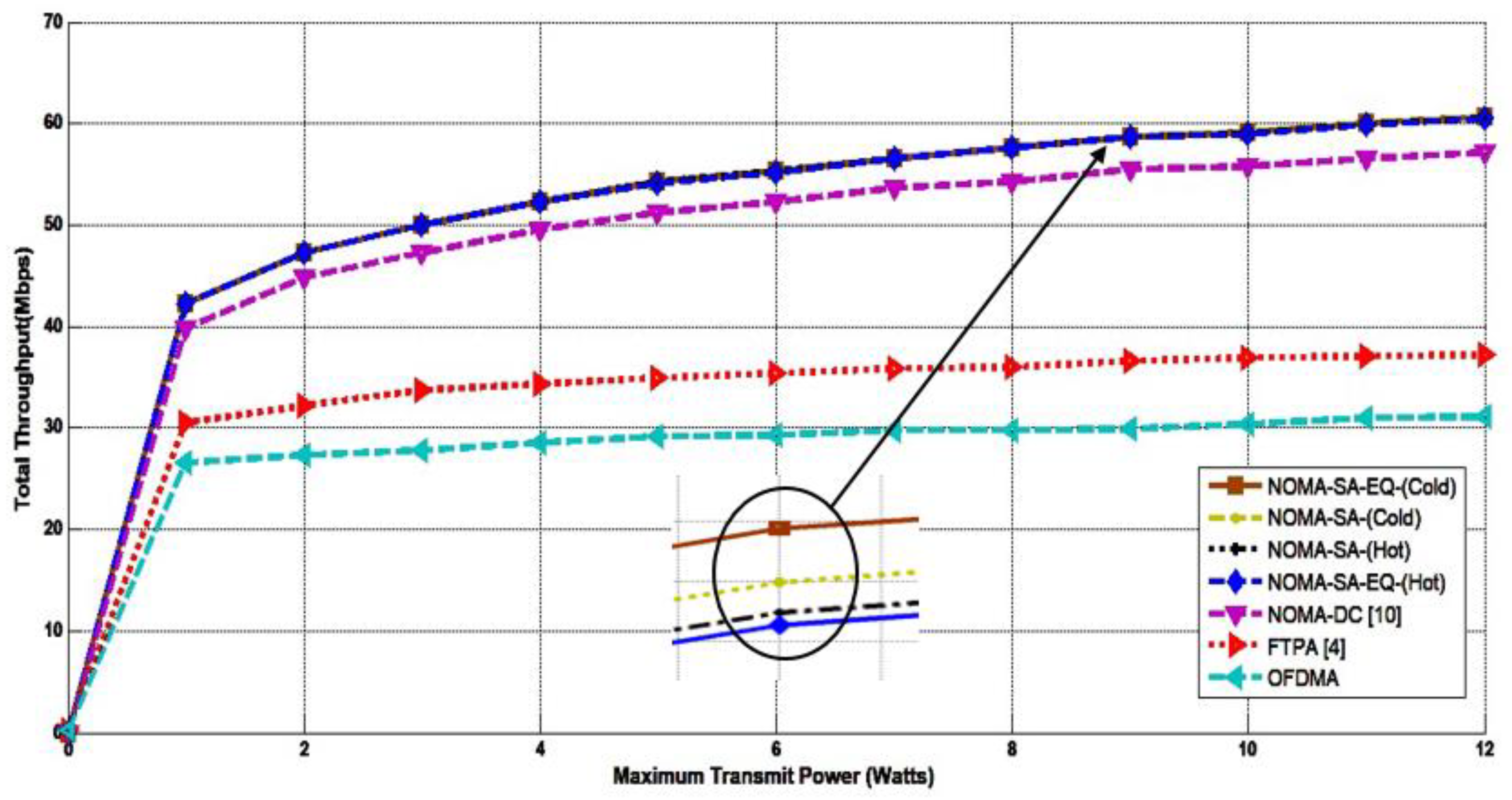
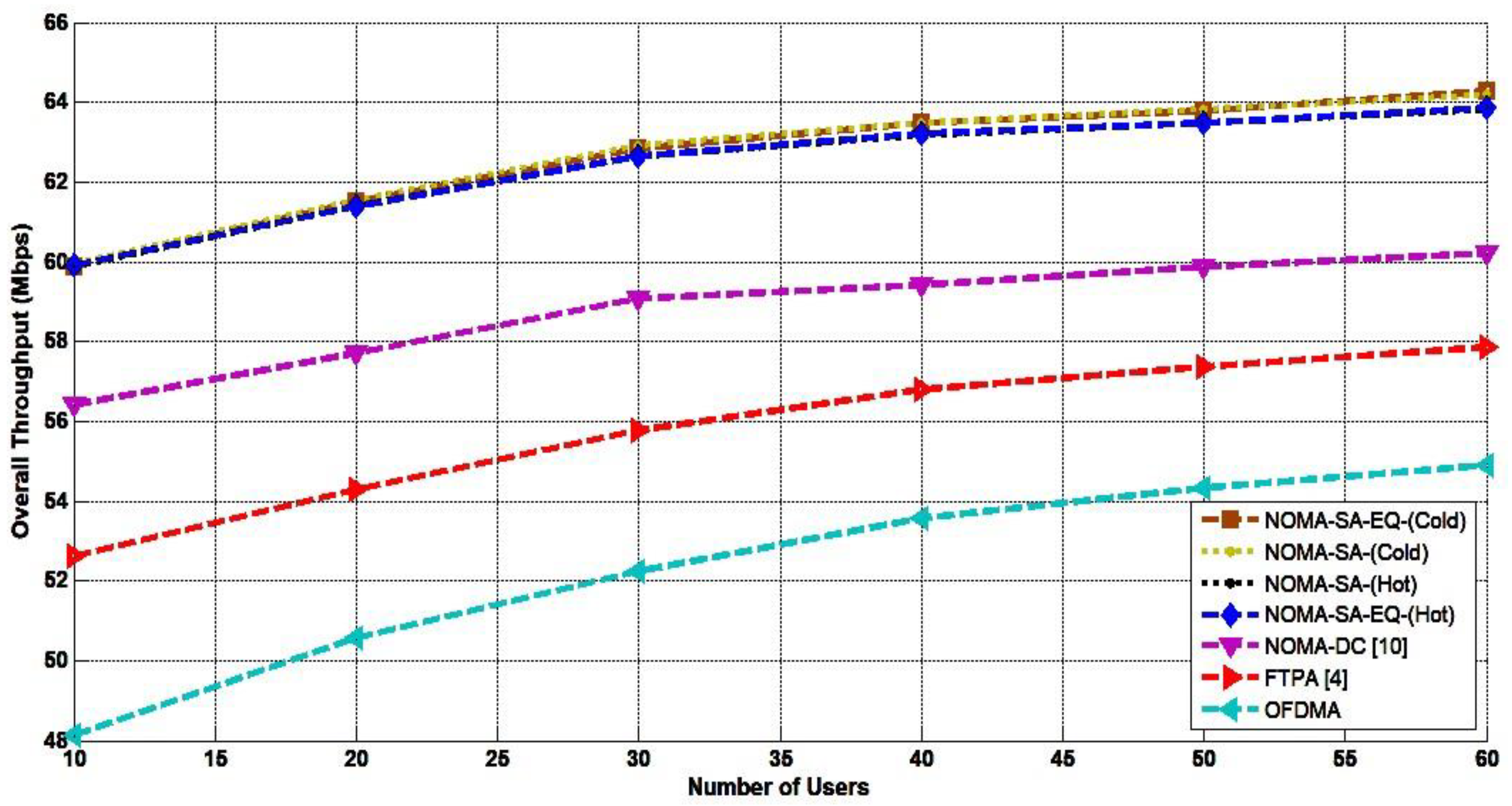
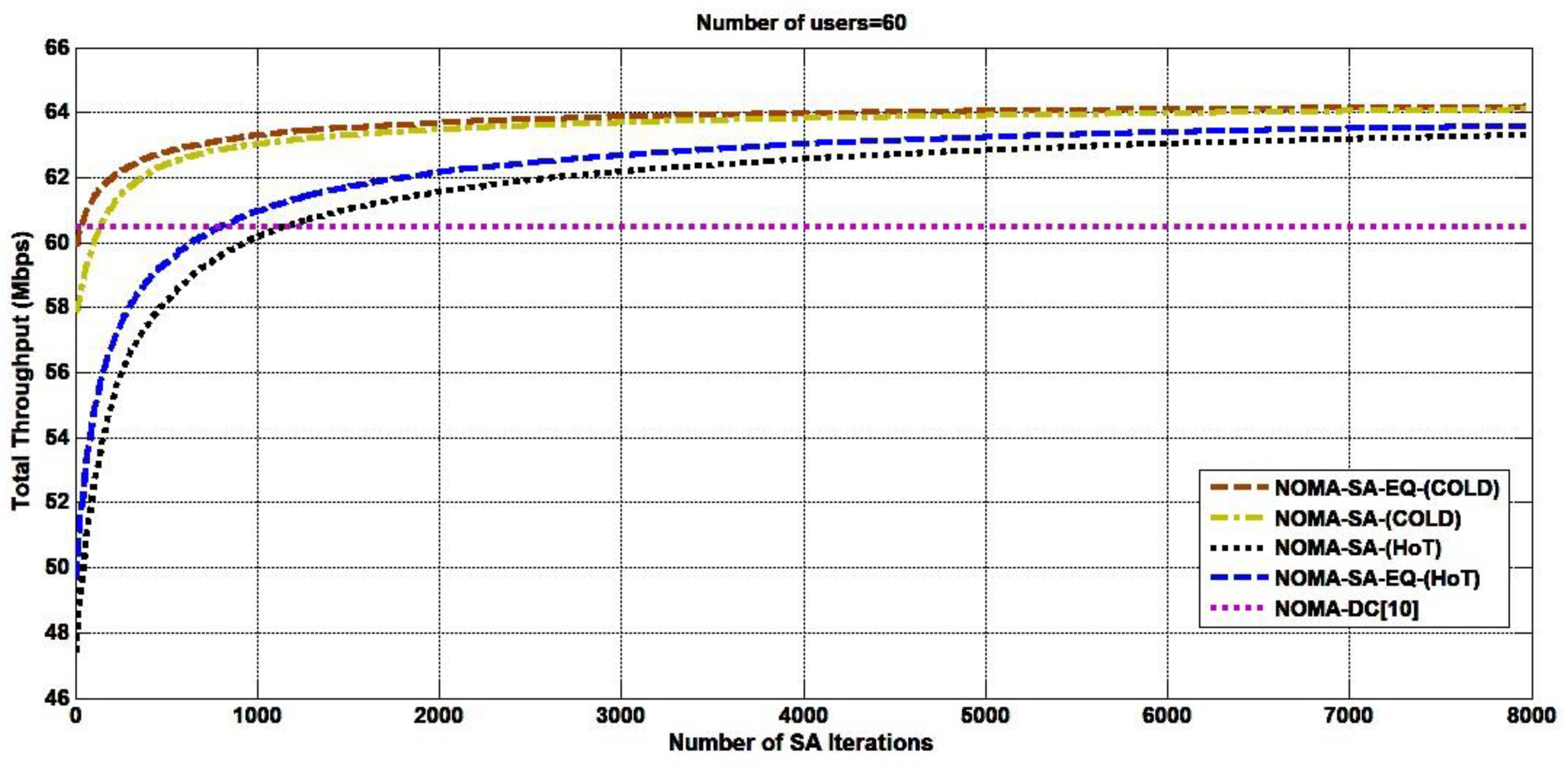
4. Result and Performance Analysis

The downlink NOMA system is simulated using MatLab and is designed with a base station at the cell’s center with a 500 m radius. In the simulation, the users are uniformly distributed to at least a 50 m minimum distance from the base station, and 40 m is the minimum distance between users. The proposed algorithm has been simulated with the system parameters shown in Table 2.
The proposed SA parameters are tuned to achieve the objective function’s maximum and ensure the algorithm’s convergence. The initial temperature is defined as T i n i t i a l = 100 , which is the highest temperature for the optimization process. Furthermore, the temperature is reduced slowly by (   T i = T i 1 α   T i 1 ) where α = 2 / 3 , which can guarantee a slow cooling schedule to obtain a global solution [22]. The SA algorithm achieves system performance with a minimum of 2000 iterations for the system that has many users.
In Figure 3, the system throughput is evaluated for 10 users versus the maximum transmission power. The SA configurations are compared to NOMA-DC [10], the fractional transmission power allocation (FTPA) [4], and OFDMA. The SA-EQ cold configuration outperforms both scenarios of the hot configuration. The search in the cold configuration starts with users experiencing a good channel gain condition that is much better than the hot configuration search. In the cold configuration, the multiplexed users’ channel condition is better than the hot configuration channel’s condition. This channel gain difference induces a reasonable solution, which can give higher Throughput for the cold configuration. The user pairing in the cold configuration is performed based on the second user channel gain on the same subchannel is better than that of the second user channel gain in the hot configuration. The SA accepts good solutions directly, but the worst solutions are accepted with a probability that can check all feasible solutions. The difference between the neighbouring solutions will not be large enough to vary the optimal solution’s probability. Both configurations show a slow increment when the power increases and reaches the maximum transmit power because of the system’s power constraints. The SA performed a power allocation that performs as 7% better than NOMA-DC and 43% higher than the FTPA performance and OFDMA. The SA computational time is 93.05 s for the system with 10 users, where the NOMA-DC is 113.5 s. Hence, SA is faster by 20.45 s than NOMA-DC because the SA reaches the optimum solution faster at the beginning and iteratively slows down to end the algorithm with limited steps.
Figure 4 shows the SA configurations compared to NOMA-DC [10], FTPA [4], and OFDMA when the number of users increased from 10 to 60 users. The presented algorithms and both SA configurations achieved a lower throughput when the system tested with 10 users, and the throughput gradually increased when the number of users increased to 60 users. The cold configuration gives higher Throughput than the hot configuration when the number of users increased. The EQ-cold configuration outperforms the other schemes because only two parameters are tuned in the system model that enhanced and expedited the search for more users. The SA computational time is 116.5 s for the system with 60 users, where the NOMA-DC is 394.05 s. Thus, the SA is faster than NOMA-DC, which is one advantage of SA for a large number of users. The equal power allocations in the cold and the hot configurations slightly outperform the other power allocations in the cold and hot configurations, hence the equal power allocation can be an optimum solution for the power allocation scheme in the NOMA system.
Figure 5 shows the cold-EQ configuration converges earlier than the hot configuration when observed on the system with 60 users. Both SA configurations converge higher than NOMA-DC, but the cold configuration shows a higher convergence than the hot configuration. For a large number of users, more iterations are required for the hot configuration which needs over 2000 iterations to converge, but these amounts of iterations are enough for cold configuration. Moreover, as the number of users increase, the SA with a cold configuration performs better because it starts from a better solution. On the other hand, the NOMA-DC is very slow for a large number of users, while the SA algorithm is relatively faster.

5. Conclusions

Simulated annealing (SA) is applied to optimize the resource allocation problem and to maximize the overall throughput in the downlink NOMA system. The SA algorithm is deployed to accomplish user assignment, determine the subchannel power, and apply the proportional power factor to the multiplexed users. The user pairing scheme is performed based on two configurations of the channel gain difference to ensure the scheme’s optimality. The power allocation is used to assign the power for each subchannel and determine the power ratio for the multiplexed users on the same subchannel. The design tested the NOMA system with a minimum of users as 10 and a maximum of 60 users. The SA algorithm outperformed by 7% the NOMA-DC, 43% FTPA, and 48% OFDM schemes with less computational time.
The SA also shows fast execution time for a large number of users and higher throughput achievement. The SA equal power allocation outperformed other power allocation schemes. It also mathematically proved that equal power allocation is the optimum power allocation scheme for the NOMA system. Moreover, according to NOMA concepts, the multiplexed users’ proportional power ratio can be fixed to a fractional value that can reduce the optimization’s complexity. The results show SA as a solution to both resource allocation problem and a way to maximize the Throughput in the NOMA-based 5G.

Author Contributions

Conceptualisation, O.A.; methodology, O.A.; software, O.A.; validation, O.A., M.B.R. and Z.B.Y.; investigation, O.A., M.B.R. and Z.B.Y.; writing–original draft preparation, O.A., M.B.R. and Z.B.Y.; writing–review and editing, O.A., M.B.R. and Z.B.Y.; visualisation, O.A., M.B.R. and Z.B.Y.; supervision, M.B.R.; project administration, O.A. All authors have read and agreed to the published version of the manuscript.

Funding

This research received no external funding.

Institutional Review Board Statement

Not applicable.

Informed Consent Statement

Not applicable.

Conflicts of Interest

The authors declare no conflict of interest.

Appendix A

The total rate of the NOMA can be expressed as:
R = B W T o t a l   n = 1 N s c l o g 2 ( 1 + δ n p n G 1 n ) + l o g 2 ( 1 + p n G 2 n ) l o g 2 ( 1 + δ n p n G 2 n )
We will define the Throughput per Bandwidth R B W = R / B W T o t a l
R B W = n = 1 N s c l o g 2 ( 1 + δ n p n G 1 , n ) + l o g 2 ( 1 + p n G 2 , n ) l o g 2 ( 1 + δ n p n G 2 , n )
Define the power allocation factor a n = P n P T o t a l , (with 1 N s c a n = 1 and 0 < a n < 1 ) where P T o t a l is the total transmit BS power and P n = a n P T o t a l we get:
R B W = n = 1 N s c l o g 2 ( 1 + δ n p n G 1 , n ) + l o g 2 ( 1 + p n G 2 , n ) l o g 2 ( 1 + δ n p n G 2 , n )
R B W = n = 1 N s c l o g 2 ( 1 + δ n a n P t G 1 , n ) + l o g 2 ( 1 + a n P t G 2 , n ) ( 1 + δ n a n P t G 2 , n )
After we simplify the equation, we get the expression 2 R B W :
2 R B W = n = 1 N s c ( ( 1 + δ n a n P t G 1 n ) ( 1 + a n P t G 2 n ) ( 1 + δ n a n P t G 2 n ) )
Under the assumption of G 1 , n > G 2 , n and δ n a n P t G 1 , n 1 ,   δ n a n P t G 2 , n 1 , which are in general valid assumptions, we get:
2 R B W ~ n = 1 N s c ( ( δ n a n P t G 1 n ) ( a n P t G 2 n ) ( δ n a n P t G 2 n ) )   ~ n = 1 N s c ( a n P t G 1 n ) = n = 1 N s c a n n = 1 N s c P t G 1 n
We know that the maximum of n = 1 N s c a n with n = 1 N s c a n = 1   and 0 < a n < 1 is the equal power allocation a n = 1 N s c where a n = P n P T o t a l , Hence P n P T o t a l = 1 N s c ; then P n = P T o t a l N s c which the exact expression of the equal power allocation.

Appendix B

Proof of the δ n power ratio:
 
The fitness function with respect to power ration δ n as following:
f ( δ n ) = B s c log 2 ( 1 + δ n P n G 1 , n ) + B s c n log 2 ( 1 + ( 1 δ n ) P n G 2 , n 1 + δ n P n G 2 , n )
With the assumption that Subchannel bandwidth is an equal distribution among the users.
f ( δ n ) = B s c log 2 ( 1 + δ n P n G 1 , n ) + B s c n log 2 ( 1 + P n G 2 , n ) B s c n log 2 ( 1 + δ n P n G 2 , n )
f ( δ n ) = B s c [ log 2 ( 1 + δ n P n G 1 , n ) + log 2 ( 1 + P n G 2 , n ) log 2 ( 1 + δ n P n G 2 , n ) ]
Change the function from log to l n :
f ( δ n ) = B s c [ log 2 ( 1 + δ n P n G 1 , n ) + log 2 ( 1 + P n G 2 , n ) log 2 ( 1 + δ n P n G 2 , n ) ]
f ( δ n ) = B s c ln 2 [ ln ( 1 + δ n P n G 1 , n ) + ln ( 1 + P n G 2 , n ) ln ( 1 + δ n P n G 2 , n ) ]
f ¯ ( δ n ) = B s c ln 2 [ P n G 1 , n ( 1 + δ n P n G 1 , n ) P n G 2 , n ( 1 + δ n P n G 2 , n ) ]
f ¯ ( δ n ) = B s c ln 2 [ P n G 1 , n ( 1 + δ n P n G 2 , n ) P n G 2 , n ( 1 + δ n P n G 1 , n ) ( 1 + δ n P n G 1 , n ) ( 1 + δ n P n G 2 , n ) ]
f ¯ ( δ n ) = B s c ln 2 [ P n G 1 , n + δ n P n 2 G 1 , n G 2 , n P n G 2 , n δ n P n 2 G 1 , n G 2 , n ( 1 + δ n P n G 1 , n ) ( 1 + δ n P n G 2 , n ) ]
f ¯ ( δ n ) = B s c ln 2 [ P n G 1 , n P n G 2 , n ( 1 + δ n P n G 1 , n ) ( 1 + δ n P n G 2 , n ) ]
f ¯ ( δ n ) = B s c ln 2 [ P n G 1 , n P n G 2 , n ( 1 + δ n P n G 1 , n ) ( 1 + δ n P n G 2 , n ) ] > 0
The function definitely increasing with respect to the increment of δ n because of the first derivative f ¯ ( δ n ) > 0 . □

References

  1. Dai, L.; Wang, B.; Yuan, Y.; Han, S.; Chih-Lin, I.; Wang, Z. Non-orthogonal multiple access for 5G: Solutions, challenges, opportunities, and future research trends. IEEE Commun. Mag. 2015, 53, 74–81. [Google Scholar] [CrossRef]
  2. Al-Falahy, N.; Alani, O.Y. Technologies for 5G networks: Challenges and opportunities. IT Prof. 2017, 19, 12–20. [Google Scholar] [CrossRef] [Green Version]
  3. Wu, Q.; Li, G.Y.; Chen, W.; Ng, D.W.K.; Schober, R. An overview of sustainable green 5G networks. IEEE Wirel. Commun. 2017, 24, 72–80. [Google Scholar] [CrossRef] [Green Version]
  4. Razavi, R.; Dianati, M.; Imran, M.A. Non-orthogonal multiple access (NOMA) for future radio access. 5G Mob. Commun. 2016, 135–163. [Google Scholar] [CrossRef]
  5. Wang, C.L.; Chen, J.Y.; Chen, Y.J. Power allocation for a downlink non-orthogonal multiple access system. IEEE Wirel. Commun. Lett. 2016, 5, 532–535. [Google Scholar] [CrossRef]
  6. Zamani, M.R.; Eslami, M.; Khorramizadeh, M. Optimal sum-rate maximization in a NOMA system with channel estimation error. In Proceedings of the 26th Iranian Conference Electrical Engineering (ICEE), Mashhad, Iran, 8–10 May 2018; pp. 720–724. [Google Scholar] [CrossRef]
  7. Sun, Q.; Han, S.; Chin-Lin, I.; Pan, Z. On the ergodic capacity of MIMO NOMA systems. IEEE Wirel. Commun. Lett. 2015, 4, 405–408. [Google Scholar] [CrossRef]
  8. Shi, H.C.; Lanjie, L.B. Pairing and power allocation for downlink nonorthogonal multiple access systems. IEEE Trans. Veh. Technol. 2017, 66, 10084–10091. [Google Scholar] [CrossRef]
  9. Parida, P.; Das, S.S. Power Allocation in OFDM Based NOMA Systems: A DC Programming Approach. In Proceedings of the 2014 IEEE Globecom Work, GC Workshops, Austin, TX, USA, 8–12 December 2014; pp. 1026–1031. [Google Scholar] [CrossRef]
  10. Fang, F.; Zhang, H.; Cheng, J.; Leung, V.C.M. Energy-efficient resource allocation for downlink non-orthogonal multiple access network. IEEE Trans. Commun. 2016, 64, 3722–3732. [Google Scholar] [CrossRef]
  11. Wang, Q.; Zhao, F. Joint spectrum and power allocation for noma enhanced relaying networks. IEEE Access 2019, 7, 27008–27016. [Google Scholar] [CrossRef]
  12. Al-Abbasi, Z.Q.; So, D.K.C. Power Allocation for Sum Rate Maximisation in Non-Orthogonal Multiple Access System. In Proceedings of the PIMRC IEEE International Symposium on Personal Indoor Mobile Radio Communications, London, UK, 7–10 September 2015; Volume 2015, pp. 1649–1653. [Google Scholar] [CrossRef]
  13. Choi, J. Power allocation for max-sum rate and max-min rate proportional fairness in NOMA. IEEE Commun. Lett. 2016, 20, 2055–2058. [Google Scholar] [CrossRef]
  14. Wang, X.; Chen, R.; Xu, Y.; Meng, Q. Low-complexity power allocation in NOMA systems with imperfect SIC for maximizing weighted sum-rate. IEEE Access 2019, 7, 94238–94253. [Google Scholar] [CrossRef]
  15. Ahmed, T.; Yasmin, R.; Homyara, H.; Hasan, M.A.F.R. Generalized power allocation (GPA) Scheme for non-orthogonal multiple access (NOMA) Based wireless communication system. Int. J. Comput. Sci. Eng. Inf. Technol. 2018, 8, 1–9. [Google Scholar] [CrossRef]
  16. Ding, Z.; Fan, P.; Poor, H.V. Impact of user pairing on 5G non-orthogonal multiple-access downlink transmissions. IEEE Trans. Veh. Technol. 2016, 65, 6010–6023. [Google Scholar] [CrossRef]
  17. Bao, W.; Chen, H.; Li, Y.; Vucetic, B. Joint rate control and power allocation for non-orthogonal multiple access systems. IEEE J. Sel. Areas Commun. 2017, 35, 2798–2811. [Google Scholar] [CrossRef] [Green Version]
  18. Zhu, J.; Wang, J.; Huang, Y.; He, S.; You, X.; Yang, L. On optimal power allocation for downlink non-orthogonal multiple access systems. IEEE J. Sel. Areas Commun. 2017, 35, 2744–2757. [Google Scholar] [CrossRef] [Green Version]
  19. Al-Abbasi, Z.Q.; So, D.K.C. Resource allocation in non-orthogonal and hybrid multiple access system with proportional rate constraint. IEEE Trans. Wirel. Commun. 2017, 16, 6309–6320. [Google Scholar] [CrossRef] [Green Version]
  20. Fu, Y.; Salaun, L.; Sung, C.W.; Chen, C.S. Subcarrier and power allocation for the downlink of multicarrier NOMA systems. IEEE Trans. Veh. Technol. 2018, 67, 11833–11847. [Google Scholar] [CrossRef]
  21. Abuajwa, O.; Tan, C.K.; Ng, Y.H.; Lee, C.K. ACO-based power allocation for throughput maximization in the downlink 5G NOMA systems. Int. J. Eng. Res. Technol. 2020, 13, 3072–3079. [Google Scholar] [CrossRef]
  22. Gallo, C.; Capozzi, V. A simulated annealing algorithm for scheduling problems. J. Appl. Math. Phys. 2019, 7, 2579–2594. [Google Scholar] [CrossRef] [Green Version]
  23. Benjebbour, A.; Li, A.; Kishiyama, Y.; Jiang, H.; Nakamura, T. System-Level Performance of Downlink NOMA Combined with SU-MIMO for Future LTE Enhancements. In Proceedings of the 2014 IEEE Globecom Work, GC Workshops, Austin, TX, USA, 8–12 December 2014; pp. 706–710. [Google Scholar] [CrossRef]
  24. Benjebbour, A.; Saito, K.; Li, A.; Kishiyama, Y.; Nakamura, T. Non-orthogonal multiple access (NOMA): Concept, Performance Evaluation and Experimental Trials. In Proceedings of the International Conference on Wireless Networks Mobile Communication (WINCOM), Marrakech, Morocco, 20–23 October 2015; pp. 1–6. [Google Scholar] [CrossRef]
Figure 1. The basic concept of the NOMA scheme with 10 users.
Applsci 11 04592 g001
Figure 2. SIC application in NOMA for each multiplexed user.
Applsci 11 04592 g002
Figure 3. System’s Throughput Versus Maximum Transmit Power 12 Watt for 10 Users.
Applsci 11 04592 g003
Figure 4. Throughput Versus Number of Users (10–60) with Maximum Transmission Power of 12 Watts.
Applsci 11 04592 g004
Figure 5. Convergence and Iterations.
Applsci 11 04592 g005
Table 1. Literature Review Summary.
ReferenceObjectiveProposed Algorithm
[5]To maximize the sum rate for SISO and MIMO NOMA system.Closed-form solution for power allocation with KKT condition.
[6]Maximize the sum rate for the NOMA system with imperfect channel state information (CSI).Optimal power using KKT condition.
[7]Maximization of the ergodic capacity.Bisection search-based power allocation.
[8]Maximize the weighted sum rate of a downlink NOMA system. Minimum mean square error (MMSE).
[9]Maximize the total sum rate for orthogonal frequency-division multiple-access (OFDM) based NOMA. User, channel matching, and iterative power allocation scheme based on the difference of convex (DC) programming.
[10]Improve Throughput and energy efficiency for the NOMA system.Subchannel matching for user and subchannel assignment and DC.
[11]Maximize the Throughput for the NOMA-enhanced relay network.Simulated annealing (SA) for subcarrier and user assignment and DC for power allocation
[12]Maximize the NOMA’s system total sum rate.Two closed-form suboptimal solutions using the Lagrange multiplier.
[13]Maximize the sum rate with minimum rate constraint for downlink NOMA with two users.The proportional fairness scheduling (PFS).
[14]Maximize the weighted sum rate (WSR).Iterative fractional quadratic transformation algorithm.
[15]Maximize the sum rate and investigate the BER performance in the NOMA system.Generalized power allocation (GPA).
[16]Maximize the sum rate by evaluating the impact of user pairing.Channel gain difference with fixed power allocation.
[17]Maximize the Throughput in the NOMA system.Lyapunov optimization framework.
[18]Improve the Throughput for the NOMA system.Two-sided matching scheme combining the power allocation and maximum fairness (MMF).
[19]Sum-rate maximization under constraints of total power and proportional rate.Hierarchical pairing power allocation (HPPA).
[20]Maximize the sum rate for MC-NOMA.Projected gradient descent algorithm and greedy heuristic search.
[21]Maximize the sum rate for NOMA.Ant colony optimization (ACO) and LTE bandwidth division.
Table 2. System Design Parameters.
ParametersValues
Bandwidth BW5 MHz
Subcarrier BW2 kHz
Cell Radius 500 m
Min distance between UE-BS50 m
Min distance between UE-UE40 m
Number of Subchannels ( N s c )128
Maximum Transmit Power ( P M a x )12 Watt
Maximum multiplexed users on the same subchannel 2 users
Total Number of users 60 users
Noise Power Spectral Density (No)−174 dBm/Hz
User Minimum Data Rate 500 b/s
Number of Transmit Antenna 1
Noise Figure 9 dBm
Shadow Standard Deviation 8 dB
Throughput calculationShannon’s capacity
Publisher’s Note: MDPI stays neutral with regard to jurisdictional claims in published maps and institutional affiliations.

