Abstract
Recently, free-space optical (FSO) communication systems utilizing unmanned aerial vehicle (UAV) relays have garnered significant attention. Integrating UAV relays into FSO communication and employing cooperative diversity techniques not only fulfill the need for long-distance transmission but also enable flexible adjustments of relay positions based on the actual environment. This paper investigates the performance of a parallel-UAV-relay-based FSO communication system. In the considered system, the channel fadings include atmospheric loss, atmospheric turbulence, pointing errors, and angle-of-arrival fluctuation. Using the established channel model, we derive a tractable expression for the probability density function of the total channel gain. Then, we derive closed-form expressions of the system outage probability (OP) and average bit error rate (ABER). Moreover, we also derive the asymptotic OP and ABER for a high-optical-intensity regime. Our numerical results validate the accuracy of the derived theoretical expressions. Additionally, the effects of the number of relay nodes, the field of view, the direction deviation, the signal-to-noise ratio threshold, the atmospheric turbulence intensity, the transmit power, and the transmission distance on the system’s performance are also discussed.
1. Introduction
1.1. Background and Motivation
Recently, free-space optical (FSO) communication has drawn widespread attention because of its inherent advantages, which include strong confidentiality, no requirement for spectrum licensing, and a high communication capacity [1,2]. However, FSO signals are highly susceptible to various fadings, such as atmospheric turbulence, atmospheric loss, and pointing errors [3]. Moreover, the performance of FSO systems is severely limited by the strict line-of-sight (LoS) alignment requirements between their transmitter and receiver [4]. To address these limitations, relay-assisted FSO communication has emerged as a promising solution [5], which is where relays are strategically deployed between the transmitter and the receiver to improve the overall performance of the system. Currently, most terrestrial FSO systems utilize fixed relays. However, due to potential obstructions in the environment in which they are deployed, the optimal placement of these relays is often unattainable, thereby restricting their practical applicability.
As unmanned aerial vehicle (UAV) technology develops rapidly, UAV relay-based FSO communication systems have received increasing amounts of attention [6]. Unlike traditional fixed terrestrial relays, UAV-assisted relays can easily establish LoS links by dynamically adjusting their positions, which can effectively address the challenges associated with relay deployment. Recently, UAV-relay-based FSO communication has become a promising candidate in many research fields, such as emergency communication and military operations [7,8,9]. In this paper, we will analyze the key performance indicators of a parallel-UAV-relay-based FSO communication system. This analysis will enable the rapid performance evaluation of such systems without the need for time-consuming simulations.
1.2. Related Works
In terms of FSO communication systems based on UAV relays, current related research primarily focuses on channel modeling and system parameter optimization. A tractable performance indicator expression is crucial for an effective system performance analysis. Specifically, the outage probability (OP) of an FSO system under a log-normal channel was analyzed [10]. An integral form of the OP for the multi-hop FSO communication system was obtained [11]. In [12], the authors analyzed the throughput of a UAV-based hybrid FSO/radio frequency (RF) system with buffer constraints. In [13], the authors studied the performance of a dual-hop fixed-gain FSO relaying system with differential detection and direct detection. In [14], a theoretical expression of the OP for FSO communication systems based on a Markov chain was obtained. However, these studies [10,11,12,13,14] fail to account for the impact of the angle of arrival (AoA) fluctuations resulting from the orientation deviations of hovering UAVs. In [15], a multi-rotor UAV-based air channel was established by comprehensively considering path loss, atmospheric turbulence, pointing error, and AoA fluctuation. For FSO communication with a high-altitude UAV, the weak atmospheric turbulence, path loss, pointing deviation, and AoA fluctuation were considered while modeling the UAV-to-UAV link [16]. In [17], an FSO channel model with weak turbulence, pointing errors, and AoA fluctuation was considered. For the multi-rotor UAV relay-based air channel, the AoA fluctuation was also discussed to demonstrate the impact of the UAV jitter [18]. However, the derived system performance expressions in [15,16,17,18] are cumbersome and intractable. Therefore, to obtain further insights, it is necessary to develop tractable theoretical expressions.
Moreover, the majority of current research on UAV-based FSO communication has primarily focused on serial relaying. For instance, in a serial UAV-based multi-hop relaying FSO system, exact and asymptotic expressions of OP were derived [19]. The performance of a triple-hop FSO system with amplification-and-forward relaying has been analyzed [20]. In [21], a regenerate-and-forward relaying scheme was proposed for an FSO serial relay-assisted system to expand its transmit distance. Using the decode-and-forward (DF) scheme, the authors of another paper optimized key parameters to minimize the outage probability of a UAV-based FSO system [22]. The throughput of a dual-hop FSO/RF hybrid system based on serial UAV relays, was maximized in [23]. When multiple UAV relays exist in the system and cooperate and communicate, the use of parallel relays can further enhance the overall performance of the system. However, the performance of a parallel-UAV-relay-based FSO system has not been extensively investigated in the available literature.
1.3. Contributions and Organization
Motivated by the issues mentioned above, this paper focuses on the error performance analysis of an FSO communication system based on parallel UAV relays. The main focus in this paper is error probability, which is a key aspect of reliable communication in Claude Shannon’s information theory. The main contributions of this paper are as follows:
- We establish a system model for parallel-UAV-relay-based FSO communication systems. We consider an FSO communication scenario with a source node, M relay nodes, and a destination node. The received signal and signal-to-noise ratio (SNR) are analyzed. We establish an FSO channel model that considers atmospheric loss, atmospheric turbulence, pointing error, and AoA fluctuation.
- We analyze the performance of a system for parallel-UAV-relay-based FSO communication. For the considered system, we obtain tractable closed-form expressions of the OP and average bit error rate (ABER). Our numerical results indicate that the simulation results are in good agreement with the theoretical results, which verifies the correctness of the expressions we derived.
- We analyze the asymptotic performance of the considered system. The theoretical expressions of the asymptotic OP and asymptotic ABER are derived at high optical powers. Through analysis, it is found that the asymptotic OP is restricted by the number of relay nodes, the field of view (FoV) of the receiver, and the standard deviation of direction deviation. However, the asymptotic ABER is only related to the FoV and the standard deviation of the direction deviation, and is independent of the number of relay nodes.
The rest of this paper is organized as follows: Section 2 provides the system model. In Section 3, closed-form expressions of the OP and ABER are derived, and the asymptotic performance of the system is also analyzed. Section 4 presents several numerical results. Finally, the conclusions are provided in Section 5.
Notation: Throughout this paper, regular font indicates a scalar. is the Gamma function; is the modified Bessel function of the second kind with order n [24]; is the Dirac delta function; is Meijer’s G-function [24]; is the probability of an event; is the cumulative distribution function (CDF) of ; and is the complementary error function.
2. System and Channel Models
2.1. System Model
We consider a parallel-UAV-relay-based FSO system consisting of a source node (S), M relay nodes (), and a destination node (D), as illustrated in Figure 1. In this system, node S and node D are installed on the top of buildings, and hovering UAVs are used as the relay nodes. We suppose that the direct transmission link between node S and node D is blocked. Moreover, node S uses laser diodes as its transmitter to send optical signals; each UAV relay node employs the DF protocol and node D uses photodiodes to receive the signal and perform photoelectric conversion.
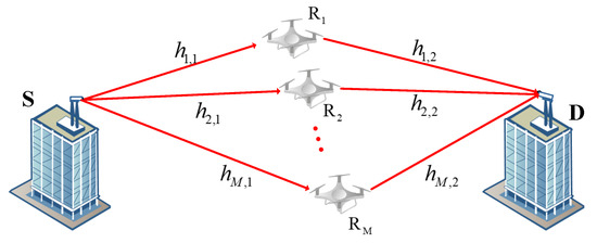
Figure 1.
Model of FSO communication system based on parallel UAV relays.
The entire communication system includes M parallel paths, and each path contains two hops. For the first hop, node S transmits the same signal to M UAV relay nodes; the signal received by UAV relay node can be written as
where T denotes the photoelectric conversion efficiency of the receiver’s photodiode at , is the channel gain between node S and node , and is the additive white Gaussian noise (AWGN) at with mean zero and variance .
In addition, the transmitted signal consists of symbols that are randomly selected with equal probability from the on–off keying (OOK) constellation such that , where denotes the average optical power of transmission. After that, the received electrical SNR of the mth link is given by
For the second hop, the node adopts the DF protocol. That is, the received signal is first decoded, and then the re-encoded signal is sent to node D. Therefore, the signal received at node D is expressed as
where is the channel gain between node and node D and is the AWGN at node D with mean zero and variance .
Similarly, the transmitted signal at each UAV relay is also considered as symbols were selected with equal probability from the OOK constellation such that , where is the average transmit power of each relay. Then, the SNR of the second hop is given by
For each path, the end-to-end SNR can be written as
To combine the received signal, a selection combining (SC) receiver is used. Compared to other combining schemes, the SC receiver is easier to implement since only one path is used for transmission. Moreover, the SC receiver is more robust in dealing with channel estimation errors since the weakest paths are excluded from the combining process. Therefore, the total SNR of the system can be expressed as
2.2. Channel Model
In this paper, the channel gain is mainly influenced by four factors [19], i.e.,
where is atmospheric loss, is atmospheric turbulence, is pointing error, and is AoA fluctuation.
According to the exponential Beers–Lambert law, the atmospheric loss can be modeled as [19]
where is the length of the jth hop of the mth path and represents the atmospheric attenuation coefficient.
For atmospheric turbulence, the Gamma–Gamma distribution is employed since it is suitable for all turbulence conditions [25]. The probability density function (PDF) of can be expressed as [26]
where and are the effective numbers of large-scale and small-scale eddies in the scattering process and given by
where denotes the Rytov variance, denotes the index of refraction structure parameter, denotes the number of light waves, and denotes the wavelength.
Based on [10], we assume that the random variances in position at each UAV are Gaussian-distributed with zero mean and variance , the random variances in the direction deviation of the UAVs are Gaussian-distributed with zero mean and variance , and the random variances in position deviation at the ground platform are Gaussian-distributed with zero mean and variance . Therefore, the PDF of the pointing error is written as
where ; is the maximal fraction of collected power, with ; is the aperture radius; is the beam waist radius at distance ; and is the equivalent beam waist. Moreover, is the variance in the total displacement for different links, which is given by
From [9,27], it is known that the link between transmitter and receiver is interrupted when the AoA of the received beam falls outside the FoV of the receiver. The PDF of can be modeled as
where is the FoV of the mth receiver at the jth hop and is the variance in the direction deviation at each UAV.
3. Performance Analysis
This section will analyze the OP and ABER of the parallel-UAV-relay-based FSO communication system before carrying out an asymptotic analysis of the system’s performance.
3.1. Outage Probability
The OP is a common metric for measuring the reliability of a wireless communication system. The OP is defined as the probability of the received SNR being smaller than a given threshold . Therefore, the OP can be expressed as
where represents the CDF of . Note that the last equality holds because the M paths are independent of each other.
According to (5), can be expressed as
where and represent the CDFs of and , respectively.
According to (2), (14), and (9.31.5) in [24], can be further written as
where is the corresponding threshold of the channel gain.
Similarly, the expression of can be obtained as
3.2. Asymptotic Outage Probability
In this subsection, the asymptotic OP will be analyzed when the average transmitted optical power at node S and the average optical power at each relay are sufficiently large.
When tends to infinity, the corresponding channel gain threshold will approach zero. According to the series expression of Meijer’s G-function [28], we can simplify (17) to
where , if ; and , if .
In (21), the term containing becomes zero when tends to infinity. Thus, the asymptotic expression of can be expressed as
Similarly, when in (18), we can derive the asymptotic expression of as
Remark 1.
By observing (25), it can be found that when the average transmit optical power and are sufficiently large, increasing the optical power does not further improve the outage performance of the system. In this case, the OP of the system is only related to the number of UAV relay nodes M, FoV , and the standard deviation of the direction deviation .
3.3. Average Bit Error Rate
The ABER is another metric commonly used to measure the performance of communication systems. It reflects the average accuracy of the data transmitted by the considered wireless communication system under all possible channel states.
For the considered system, the end-to-end ABER is related to the ABER of each path, which is their minimum bit error value. In particular, when all paths are independent and identically distributed, the end-to-end ABER of the system is equal to the ABER of a single path. In this case, the ABER of the system can be derived.
Assuming that the receiver uses OOK modulation and direct detection, the end-to-end BER conditioned on the channel gain for the path is expressed as
where and are the probabilities that the transmitted power is 0 and , respectively.
Since and , Equation (26) can be further written as
where is the average transmit optical power of node S or each relay and is the standard variance of noise at each relay or node D. Specifically, when , and ; when , and .
Due to the effect of channel fading, the jth hop’s ABER can be expressed as
where denotes the ABER of the first hop (i.e., the source-to-relay link) and denotes the ABER of the second hop (i.e., the relay-to-destination link).
Substituting (14) and (29) into (30), we can obtain the expression for the jth hop ABER, which is as follows:
According to [30], the ABER of the dual-hop system meets the following conditions:
where is the ABER from the source node to the relay node or destination node .
Thus, the total ABER from node S to node D can be expressed as
3.4. Asymptotic Average BER
This subsection will derive the asymptotic bound of the ABER when the average transmit optical power is sufficiently large.
According to the series expression of Meijer’s G-function [24], when tends to infinity, we can express (31) as
where , if . Moreover, if .
In (35), when the average transmitted optical power tends to infinity, the term containing tends to zero. Thus, the asymptotic expression of can be expressed as
Remark 2.
In (37), when , increasing will not further improve the ABER of the system. In this situation, the ABER of the system is only related to the FoV and the standard deviation of direction deviation and is independent of the number of relay nodes.
4. Numerical Results
In this section, Monte-Carlo simulations will be provided to verify the correctness of the theoretical expressions we have derived, and the impacts of various parameters on the system’s performance will be provided. In all simulation figures, the theoretical results of the OP and asymptotic OP are determined by (20) and (25), respectively. The theoretical results of the ABER and asymptotic ABER are determined by (34) and (37), respectively. To evaluate Meijer’s G-function in our theoretical expressions, we use the software MATLAB R2023a. To facilitate the simulation, the optical power transmitted at node S and each relay are assumed to be the same, i.e., . The main simulation parameters used in this paper are shown in Table 1.

Table 1.
The main parameters used in this paper.
4.1. OP Results
Figure 2 shows the OP versus the average transmitted optical power for different relay numbers M when and . As can be observed, for a given M, the OP gradually decreases with the . Under the same , the OP decreases significantly with an increase in M. This means that increasing the number of parallel relay nodes can significantly improve the system’s outage performance. In addition, when is large, the OP of the system does not decrease with the increase in but tends to the corresponding asymptotic bound. This indicates that increasing the average transmitted optical power cannot always improve the outage performance of the system, which verifies the conclusion in Remark 1.
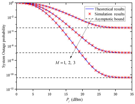
Figure 2.
System OP versus under different M when and .
Figure 3 shows the OP versus for different when and . As can be seen, when is small, the system’s OP gradually decreases with the decrease in . Obviously, the smaller the link transmission distance is, the better the channel quality is. However, when is sufficiently large, the OP does not continuously decrease with the increase in but gradually approaches its asymptotic bound, which verifies the accuracy of (25). Such an observation suggests that when is sufficiently large, the average transmitted optical power will no longer affect the OP performance of the system. In this situation, the relay numbers M, the FoV , and the standard deviation of the direction deviation limit the system’s outage performance. In addition, when is large, the system’s OP curves tend to the same asymptotic bound under different . That is to say, its asymptotic bound is independent of . Therefore, the limiting factor affecting the system’s OP is no longer , which verifies the conclusion in Remark 1.

Figure 3.
System OP versus under different when and .
Figure 4 shows the OP versus for different when and . As can be observed, when is small, the OP performance becomes worse as increases. By observing (9) and (10), we can conclude that the PDF of is only affected by . Therefore, when is small, the effect of atmospheric turbulence on the OP is reduced by reducing . When is large, the OP curves of the system tend to the same asymptotic bound under different . It should be noted that the asymptotic value is independent of and the turbulence condition of , which verifies Remark 1.

Figure 4.
System OP versus under different when and .
Figure 5 shows the OP versus for different SNR threshold values when and . It can be observed from the figure that when is small, the system’s OP performance becomes worse as the increases, which suggests that a better OP performance for the system can be obtained by reducing the value of . In addition, when is large, the OP curves of the system tend to the same asymptotic bound, which is independent of and the SNR threshold , thus verifying Remark 1.
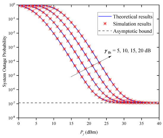
Figure 5.
System OP versus average transmitted optical power for different when and .
Figure 6 shows the OP versus for different when and . As seen in the figure, the OP gradually decreases as is increased for a given . However, when is large, the OP performance does not improve as increases, but tends to different asymptotic bounds due to different values. This indicates that the system’s OP performance cannot always be improved by increasing without limitation, which verifies the accuracy of Remark 1.
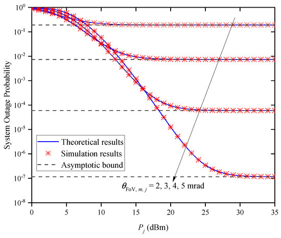
Figure 6.
System OP versus for different when and .
Figure 7 shows the OP versus the FoV for different average transmitted optical powers when and . It can be observed that the OP decreases first and then increases as the increases for a given . This indicates that there is an optimal value for obtaining the best outage performance, and the optimal value gradually increases with the increase in .
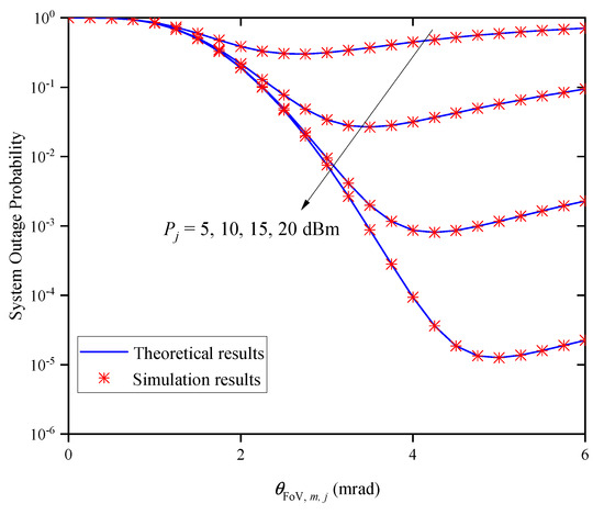
Figure 7.
System OP versus FoV for different when and .
Figure 8 shows the OP versus for different when and . In this figure, the OP gradually decreases with the increase in for a fixed . When the transmitted optical power conditions are the same, the system OP increases with the increase in , which suggests that a better OP performance for the system can be obtained by decreasing the value of . Moreover, when is large, the OP performance does not decrease with the increase in but approaches different asymptotic bounds due to different values. This indicates that the system’s OP performance cannot be enhanced by increasing without limitation, which verifies the accuracy of Remark 1.

Figure 8.
System OP versus for different when and .
From Figure 2, Figure 3, Figure 4, Figure 5, Figure 6, Figure 7 and Figure 8, it can be observed that the performance gaps between all theoretical and simulation results are so small that they can be ignored. This indicates that the obtained theoretical expression of the OP can be utilized to evaluate a system’s outage performance without the need for time-intensive simulations.
4.2. ABER Results
Figure 9 shows the system’s ABER versus for different numbers of relay nodes M when and . It can be seen that the system’s ABER gradually decreases with the increase in for a given M value. Under the same transmitted optical power condition, the system’s ABER does not change with the increase in M, because the system ABER is equal to the ABER of a single path and is independent of M, when the states of each path are independent and identically distributed. Moreover, the system ABER does not decrease with the increase in , but approaches the same asymptotic bound. This indicates that increasing the cannot always improve the system’s ABER performance, which verifies the accuracy of Remark 2.
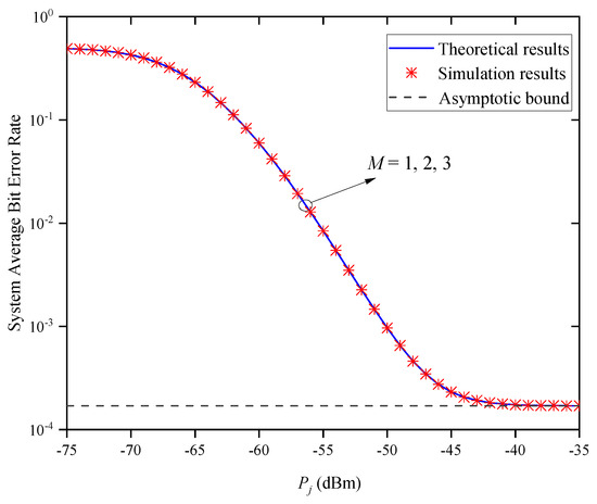
Figure 9.
System ABER versus for different M when and .
Figure 10 shows the system’s ABER versus for different when and . In Figure 10, the system’s ABER dramatically decreases with the decrease in when is small. This is obvious because the shorter the link transmission distance is, the better the channel quality is. However, when is large, the system’s ABER does not continuously decrease with the increase in , but gradually approaches the asymptotic bound, which verifies the accuracy of (37). This phenomenon suggests that when is large enough, the average transmitted optical power does not affect the system’s ABER. Moreover, the system’s ABER curves approach the same asymptotic bound when is large; that is, the asymptotic bound is independent of and the parameter that affects the system’s ABER is no longer , which verifies the accuracy of Remark 2.
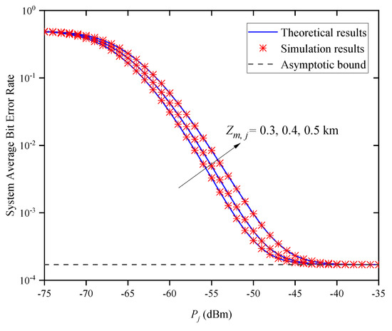
Figure 10.
System ABER versus for different when and .
Figure 11 shows the system’s ABER versus for different when and . In the figure, we find that the system BER increases with the increase in when is small. According to (9) and (10), we can conclude that the PDF of is only determined by . Thus, when the average transmitted optical power is small, we can reduce the effect of atmospheric turbulence on the system’s BER by decreasing . Under different conditions, the system’s BER curves approach the same asymptotic bound as when the average transmitted optical power is large; this asymptotic value is independent of and the turbulence condition , which verifies the accuracy of Remark 2.
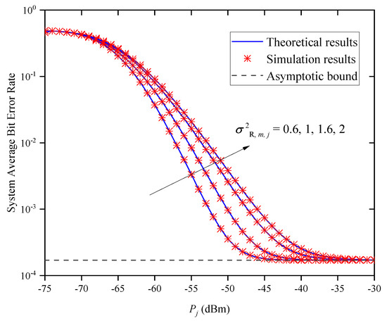
Figure 11.
System ABER versus for different when and .
Figure 12 shows the system’s ABER versus for different FoVs when and . In the figure, we find that the system’s ABER gradually decreases with the increase in for a given . When is large, the system’s ABER does not decrease with the increase in , but approaches different asymptotic bounds due to the different values of . This indicates that the system’s ABER cannot always be decreased by increasing , which verifies the accuracy of Remark 2.

Figure 12.
System ABER versus for different when and .
Figure 13 shows the system’s ABER versus the FoV for different values of when and . In this figure, we find that the system’s ABER decreases first and then increases as increases for a given . This indicates that there is an optimal value for obtaining the minimum system ABER, and the optimal value increases gradually with the increase in .
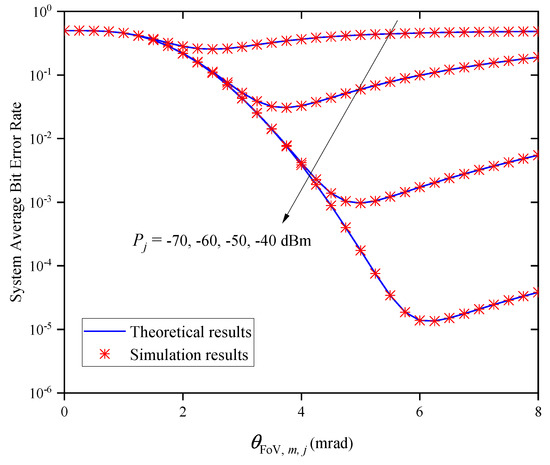
Figure 13.
System ABER versus FoV for different when and .
Figure 14 shows the system ABER versus for different standard deviations of the direction deviation when and . In this figure, we find that the system’s ABER decreases with the increase in for a given . Under the different conditions, the system’s ABER increases with the increase in . This indicates that we can obtain a smaller ABER by reducing the value of . In addition, when is large, the system’s ABER does not decrease with the increase in but approaches different asymptotic bounds because of different values of . This indicates that the system’s ABER cannot always be decreased by increasing , which verifies the accuracy of Remark 2.
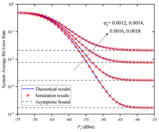
Figure 14.
System ABER versus average transmitted optical power for different when and .
From Figure 9, Figure 10, Figure 11, Figure 12, Figure 13 and Figure 14, we can conclude that all theoretical values match the simulation values well. Thus, the obtained ABER expression could be directly employed to evaluate the system’s error performance without the need for time-consuming simulations.
5. Conclusions
In this work, we investigated the outage and error performance of a parallel-UAV-relay-based FSO communication system. By considering the atmospheric loss, atmospheric turbulence, pointing error, and AoA fluctuation, we derived the PDF of the overall channel gain and closed-form expressions of the OP and the ABER. Moreover, we also analyzed the asymptotic bounds of the OP and ABER. Our numerical results verified the accuracy of the theoretical expressions we derived. Moreover, the results indicated that the system’s OP is related to the number of relay nodes, the FoV, and the standard deviation of the direction deviation, while the ABER is only related to the FoV and the standard deviation of the direction deviation.
Author Contributions
Conceptualization, S.-H.L.; methodology, J.-Y.W.; software, S.-H.L.; validation, X.H. and J.-Y.W.; investigation, X.H.; resources, J.-Y.W.; writing—original draft preparation, S.-H.L. and J.-Y.W.; writing—review and editing, S.-H.L., X.H. and J.-Y.W. All authors have read and agreed to the published version of the manuscript.
Funding
This research was funded by the National Natural Science Foundation of China, under Grant 62472233, and the Natural Science Foundation of Jiangsu Province, under Grant BK20221328.
Institutional Review Board Statement
Not applicable.
Data Availability Statement
The data presented in this study are available on request from the corresponding author.
Acknowledgments
The authors thank the anonymous reviewers and the Editor for their helpful comments and review of this article.
Conflicts of Interest
Author Xinyi Hua was employed by the Jiangsu Province Special Equipment Safety Supervision Inspection Institute. The remaining authors declare that the research was conducted in the absence of any commercial or financial relationships that could be construed as a potential conflict of interest.
Abbreviations
The following abbreviations are used in this manuscript:
| ABER | average bit error rate |
| AoA | angle of arrival |
| AWGN | additive white Gaussian noise |
| CDF | cumulative distribution function |
| DF | decode-and-forward |
| FoV | field of view |
| FSO | free-space optical |
| OOK | on–off keying |
| OP | outage probability |
| probability density function | |
| RF | radio frequency |
| SC | selection combining |
| SNR | signal-to-noise ratio |
| UAV | unmanned aerial vehicle |
References
- Fayad, A.; Cinkler, T.; Rak, J. Toward 6G optical fronthaul: A survey on enabling technologies and research perspectives. IEEE Commun. Surv. Tutor. 2025, 27, 629–666. [Google Scholar] [CrossRef]
- Elamassie, M.; Uysal, M. Multi-layer airborne FSO systems: Performance analysis and optimization. IEEE Trans. Commun. 2025, 73, 2522–2537. [Google Scholar] [CrossRef]
- Xu, F.; Duo, B.; Xie, Y.; Pan, G.; Yang, Y.; Zhang, L.; Ye, Y.; Bao, T.; Gulliver, T.A.; Wang, Y. Multi-UAV assisted mixed FSO/RF communication network for urgent tasks: Fireness oriented design with DRL. IEEE Trans. Veh. Technol. 2025, 74, 1736–1741. [Google Scholar] [CrossRef]
- Wang, J.-Y.; Wang, J.-B.; Chen, M.; Tang, Y.; Zhang, Y. Outage analysis for relay-aided free-space optical communications over turbulence channels with nonzero boresight pointing errors. IEEE Photonics J. 2014, 6, 1–15. [Google Scholar]
- Zhang, X.; Zhao, S.; Wang, Y.; Wang, X.; Song, X.; Li, X.; Li, J. 3-D trajectory optimization for UAV-assisted hybrid FSO/RF network with moving obstacles. IEEE Trans. Aerosp. Electron. Syst. 2025, 61, 1692–1704. [Google Scholar] [CrossRef]
- Fawaz, W.; Abou-Rjeily, C.; Assi, C. UAV-aided cooperation for FSO communication systems. IEEE Commun. Mag. 2018, 56, 70–75. [Google Scholar] [CrossRef]
- Alzenad, M.; Shakir, M.Z.; Yanikomeroglu, H.; Alouini, M.-S. FSO-based vertical backhaul/fronthaul framework for 5G+ wireless networks. IEEE Commun. Mag. 2018, 56, 218–224. [Google Scholar] [CrossRef]
- Dong, Y.; Hassan, M.Z.; Cheng, J.; Hossain, M.J.; Leung, V.C.M. An edge computing empowered radio access network with UAV mounted FSO fronthaul and backhaul: Key challenges and approaches. IEEE Wirel. Commun. 2018, 25, 154–160. [Google Scholar] [CrossRef]
- Zeng, Y.; Wu, Q.; Zhang, R. Accessing from the sky: A tutorial on UAV communications for 5G and beyond. Proc. IEEE 2019, 107, 2327–2375. [Google Scholar] [CrossRef]
- Farid, A.A.; Hranilovic, S. Outage capacity optimization for free-space optical links with pointing errors. J. Light. Technol. 2017, 25, 1702–1710. [Google Scholar] [CrossRef]
- Safari, M.; Uysal, M. Relay-assisted free-space optical communication. IEEE Wirel. Commun. 2008, 7, 5441–5449. [Google Scholar] [CrossRef]
- Lee, J.H.; Park, K.H.; Ko, Y.C.; Alouini, M.S. Throughput maximization of mixed FSO/RF UAV-aided mobile relaying with a buffer. IEEE Trans. Wirel. Commun. 2021, 20, 683–694. [Google Scholar] [CrossRef]
- Zedini, E.; Soury, H.; Alouini, M.S. Dual-hop FSO transmission systems over Gamma-Gamma turbulence with pointing errors. IEEE Trans. Wirel. Commun. 2017, 16, 784–796. [Google Scholar] [CrossRef]
- Abou-Rjeily, C.; Fawaz, W. Buffer-aided serial relaying for FSO communications: Asymptotic analysis and impact of relay placement. IEEE Trans. Wirel. Commun. 2018, 17, 8299–8313. [Google Scholar] [CrossRef]
- Najafi, M.; Ajam, H.; Jamali, V.; Diamantoulakis, P.D.; Karagiannidis, G.K.; Schober, R. Statistical modeling of FSO fronthaul channel for drone-based networks. In Proceedings of the 2018 IEEE International Conference on Communications (ICC), Kansas City, MO, USA, 20–24 May 2018. [Google Scholar]
- Mai, V.V.; Kim, H. Beam size optimization and adaptation for high-altitude airborne free-space optical communication systems. IEEE Photonics J. 2019, 11, 7902213. [Google Scholar] [CrossRef]
- Huang, S.; Safari, M. Free-space optical communication impaired by angular fluctuations. IEEE Trans. Wirel. Commun. 2017, 16, 7475–7487. [Google Scholar] [CrossRef]
- Dabiri, M.T.; Sadough, S.M.S.; Khalighi, M.A. Channel modeling and parameter optimization for hovering UAV-based free-space optical links. IEEE J. Sel. Areas Commun. 2018, 36, 2104–2113. [Google Scholar] [CrossRef]
- Wang, J.-Y.; Ma, Y.; Lu, R.-R.; Wang, J.-B.; Lin, M.; Cheng, J. Hovering UAV-based FSO communications: Channel modelling, performance analysis, and parameter optimization. IEEE J. Sel. Areas Commun. 2021, 39, 2946–2959. [Google Scholar] [CrossRef]
- Mohd, N.; Ghassemlooy, Z.; Zvanovec, S.; Khalighi, M.A.; Bhatnagar, M.R.; Bohata, J.; Komanec, M. Experimental analysis of a triple-hop relay-assisted FSO system with turbulence. Opt. Switch. Netw. 2019, 33, 194–198. [Google Scholar] [CrossRef]
- Nor, N.A.M.; Komanec, M.; Bohata, J.; Ghassemlooy, Z.; Bhatnagar, M.R.; Zvanovec, S. Experimental all-optical relay-assisted FSO link with regeneration and forward scheme for ultra-short pulse transmission. Opt. Exp. 2019, 27, 22127–22137. [Google Scholar] [CrossRef]
- Dabiri, M.T.; Sadough, S.N.S. Optimal placement of UAV-assisted free-space optical communication systems with DF relaying. IEEE Commun. Lett. 2020, 24, 155–158. [Google Scholar] [CrossRef]
- Lee, J.H.; Park, K.H.; Alouini, M.S.; Ko, Y.C. On the Throughput of Mixed FSO/RF UAV-Enabled Mobile Relaying Systems with a Buffer Constraint. In Proceedings of the ICC 2019—2019 IEEE International Conference on Communications (ICC), Shanghai, China, 20–24 May 2019. [Google Scholar]
- Gradshteyn, I.S.; Ryzhik, I.M. Table of Integrals, Series, and Products, 7th ed.; Academic: New York, NY, USA, 2007. [Google Scholar]
- Andrews, L.C.; Phillips, R.L.; Hopen, C.Y.; Al-Habash, M.A. Theory of optical scintillation. J. Opt. Soc. Amer. A 1999, 16, 1417–1429. [Google Scholar] [CrossRef]
- Pham, T.V.; Thang, T.C.; Pham, A.T. Average achievable rate of spatial diversity MIMO-FSO over correlated Gamma-Gamma fading channels. IEEE/OSA J. Opt. Commun. Netw. 2018, 10, 662–674. [Google Scholar] [CrossRef]
- Wang, J.-Y.; Liu, C.; Wang, J.-B.; Wu, Y.; Lin, M. Physical-layer security for indoor visible light communications: Secrecy capacity analysis. IEEE Trans. Commun. 2018, 66, 6423–6436. [Google Scholar] [CrossRef]
- Abou-Rjeily, C.; Noun, Z. Impact of inter-relay co-operation on the performance of FSO systems with any number of relays. IEEE Trans. Wirel. Commun. 2016, 15, 3796–3809. [Google Scholar] [CrossRef]
- Sandalidis, H.G.; Tsiftsis, T.A.; Karagiannidis, G.K.; Uysal, M. BER performance of FSO links over strong atmospheric turbulence channels with pointing errors. IEEE Commun. Lett. 2008, 12, 44–46. [Google Scholar] [CrossRef]
- Wang, J.-B.; Sheng, M.; Song, X.-Y.; Jiao, Y.; Chen, M. Comments on ‘BER performance of FSO links over strong atmospheric turbulence channels with pointing errors’. IEEE Commun. Lett. 2012, 16, 22–23. [Google Scholar] [CrossRef]
Disclaimer/Publisher’s Note: The statements, opinions and data contained in all publications are solely those of the individual author(s) and contributor(s) and not of MDPI and/or the editor(s). MDPI and/or the editor(s) disclaim responsibility for any injury to people or property resulting from any ideas, methods, instructions or products referred to in the content. |
© 2025 by the authors. Licensee MDPI, Basel, Switzerland. This article is an open access article distributed under the terms and conditions of the Creative Commons Attribution (CC BY) license (https://creativecommons.org/licenses/by/4.0/).