2.1. Basic Composition and Mathematical Model of NRPCS
A system block diagram provides a clear and intuitive understanding of the entire system’s operation.
Figure 1 presents the transmitter block diagram of the Noise-like Multi-Carrier Random Phase Communication System (NRPCS). The transmitter primarily comprises modules for amplitude spectrum formation, random phase mapping, time-domain basis function generation via an inverter, data modulation, data memory, radio frequency transmission, and antenna components. Additionally, modules for energy and power regulation as well as storage are included to facilitate efficient signal processing. At the core of the NRPCS is the construction of basic modulation waveforms possessing specialized characteristics. Specifically, waveforms are generated through random phase mapping and amplitude spectrum shaping, subsequently transformed to synthesize time-domain basis functions exhibiting covert characteristics. Data modulation is then achieved by mapping these synthesized time-domain basis functions in various manners, enabling effective information transmission. The NRPCS utilizes random-phase waveforms, which demonstrate prominent noise-like characteristics, significantly enhancing covert communication capabilities and physical-layer security.
As illustrated in
Figure 1, the basic implementation process of NRPCS is as follows: the electromagnetic environment is dynamically sampled within a designed system bandwidth, after which spectrum estimation is performed. The resulting estimated amplitude spectrum vector
is then evaluated against a predetermined threshold to identify spectrum segments experiencing interference and those that remain unoccupied, thereby suitable for signal transmission. By employing a targeted thresholding technique, interference is effectively suppressed, producing a “clean” amplitude spectrum vector
that excludes interfered or occupied frequency components. This step is known as amplitude spectrum shaping. The vector
is then multiplied by a complex random phase vector of equal length
, generated by a phase mapper. The result is
, which serves the purpose of assigning a random phase to each available frequency point, giving the time-domain communication signal a noise-like characteristic.
The receiver structure of the NRPCS is depicted in
Figure 2, representing the inverse operation of the transmitter. The receiving end primarily comprises components such as an antenna, RF receiver, data cache and synchronization modules, a peak finder, and demodulation circuits. To maintain consistency with the fundamental modulation waveform produced by the transmitter, the receiver must similarly execute procedures like amplitude spectrum generation and random phase mapping to reconstruct the time-domain basis functions. Amplitude spectrum generation ensures that the frequency-domain characteristics of the received signals match those of the transmitted modulation signals. Random phase mapping at the receiver aims to compensate for and correct random phase shifts introduced during signal transmission. Phase variations may occur due to environmental noise, multipath propagation effects, or other environmental factors. Thus, accurate phase correction at the receiver is essential for effective demodulation and accurate retrieval of the transmitted data.
Each CCSK sequence is generated through a periodic shift of the base sequence. According to this feature, the receiver employs a cyclic correlation detection method for signal recovery [
16]. Specifically, the received signal undergoes a cyclic correlation operation with the locally stored base sequence. By analyzing the positional difference between the resultant correlation peak and the inherent peak of the base sequence, the receiver determines the shift value of the CCSK codeword. Consequently, the corresponding data information encoded in the shifted code is effectively extracted.
2.2. Amplitude Spectrum Molding
Amplitude spectrum shaping is a technique used to optimize the signal transmission spectrum. It involves comparing the environmental spectral information matrix with a predefined threshold to determine which frequencies within a specified bandwidth are unavailable and which remain unoccupied and suitable for transmission. This procedure results in a usable spectral matrix, serving as the amplitude spectrum for the corresponding time-domain basis function.
According to the findings presented in Reference [
17]. The amplitude spectrum design primarily determines the amplitude of the Fundamental Modulation Waveform (FMW). Specifically, the amplitude spectrum is derived from processing the Power Spectral Density (PSD) estimated from the signal spectrum. The threshold utilized in this context is determined based on the average power across the system bandwidth, effectively suppressing interference spectral components. Currently, two primary methods are employed for spectrum shaping: flat amplitude molding and coded amplitude molding.
In flat amplitude molding, if the amplitude of an interference spectrum exceeds the preset threshold, the amplitude at that frequency point is set to zero; otherwise, it is set to one, resulting in an FMW amplitude spectrum composed exclusively of binary values (0 or 1). Conversely, coded amplitude molding takes channel conditions into account by setting the amplitude spectrum based on the channel transmission function. In this approach, if the interference amplitude surpasses the threshold, the spectral component’s amplitude is set accordingly.
According to the findings presented in Reference [
18]. Previous research has applied coded amplitude molding to analyze spectrum shaping performance under multipath fading channels. The findings indicate that, when the number of multipath components varies from 2 to 50, the coded amplitude molding method achieves an improvement in Signal-to-Noise Ratio (SNR) of approximately 1 to 2.75 dB compared to flat amplitude molding. Furthermore, in practical applications, Doppler frequency shifts also represent a significant channel factor that must not be neglected. Therefore, investigating spectrum shaping techniques under Doppler frequency shift conditions remains essential for comprehensive performance assessment.
2.3. Noise-like Random Phase Signal Generation Method
This section focuses on the generation method of noise-like random phase signals. Random phase mapping serves three primary purposes in the NRPCS system. First, it imparts noise-like characteristics to the transmitted signals, thereby enhancing the system’s low probability of detection and low probability of interception. Second, the cross-correlation between different random phase sequences is minimal, while the autocorrelation of an individual sequence is highly prominent. This property supports the system’s multiple access capability. Third, the inherent correlation characteristics facilitate efficient modulation and demodulation processes.
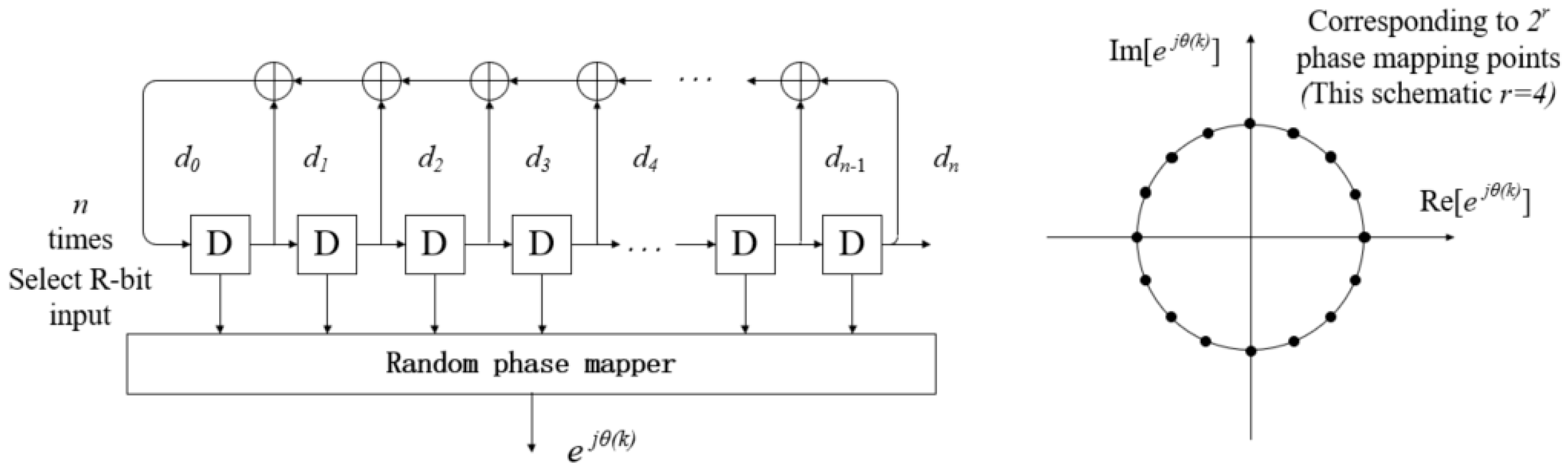
In random phase communication systems, random phase mapping is often implemented using m-sequences. As shown in
Figure 3, these sequences are generated based on the cyclic operation of a Linear Feedback Shift Register (LFSR) [
19]. To begin, the number of register stages
must be determined, and a primitive polynomial—one that is irreducible and possesses a maximum period—is selected as the feedback logic coefficient. During initialization, the register is typically set to all zeros, except for the last bit, which is initialized to one to avoid the all-zero deadlock state. In each shift operation, a new bit is produced by performing XOR operations on specific register bits, as dictated by the coefficients of the primitive polynomial. Subsequently, all register states are shifted one position to the right, and the newly generated bit is inserted into the leftmost register position.
During the phase mapping process, registers are selected from the -stage LFSR to serve as the input to the phase mapper. These register values can map up to random phase points. The selection of the registers can be any arbitrary combination or a consecutive set of registers. Consecutive selection helps ensure a more uniform distribution of values in the resulting pseudo-random multivariate sequence.
Let the generated random phase sequence be
among
,
,
.
By altering the primitive polynomial configuration of the Linear Feedback Shift Register (LFSR), multiple distinct pseudo-random polyphase sequences can be generated through random phase mapping. These sequences serve as the basis for constructing different fundamental modulation waveforms. By assigning specific pseudo-random polyphase sequences to individual users and leveraging the quasi-orthogonality among the resulting fundamental modulation waveforms, multi-user access can be effectively achieved in a random phase communication system.
2.4. Time Domain Basis Function Generation
Time-Domain Basis Function Generation refers to the process of constructing fundamental time-domain waveforms that act as the foundational elements for signal modulation in communication systems. These basis functions are essential for shaping the characteristics of the transmitted signal. The corresponding frequency-domain basis function matrix is obtained by performing an element-wise multiplication (inner product) between the constructed amplitude spectrum matrix
and the generated random phase matrix
. This operation yields a composite frequency-domain representation, which is then transformed into the time domain to produce the desired basis functions with noise-like properties [
20].
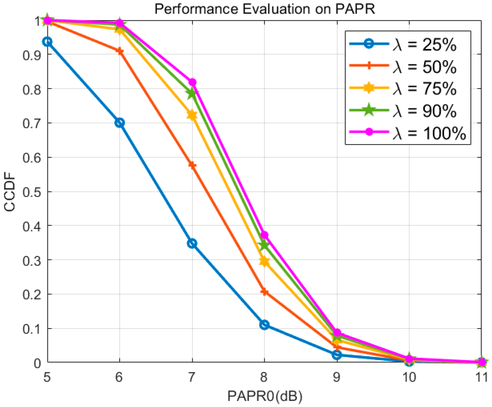
Due to the uncertainty in the number of subcarriers available within the usable spectrum, it is necessary to perform amplitude adjustment of the basis function in the frequency domain. This adjustment is crucial to mitigate excessive power fluctuations that may arise from variations in the spectral matrices. By normalizing the amplitude, the system not only reduces circuit complexity but also eliminates the requirement for automatic gain control prior to signal amplification at the transmitter end. Here, the adjustment factor
is introduced, where
is all the frequency points and
is the available frequency points, thus the frequency domain basis function after amplitude adjustment is
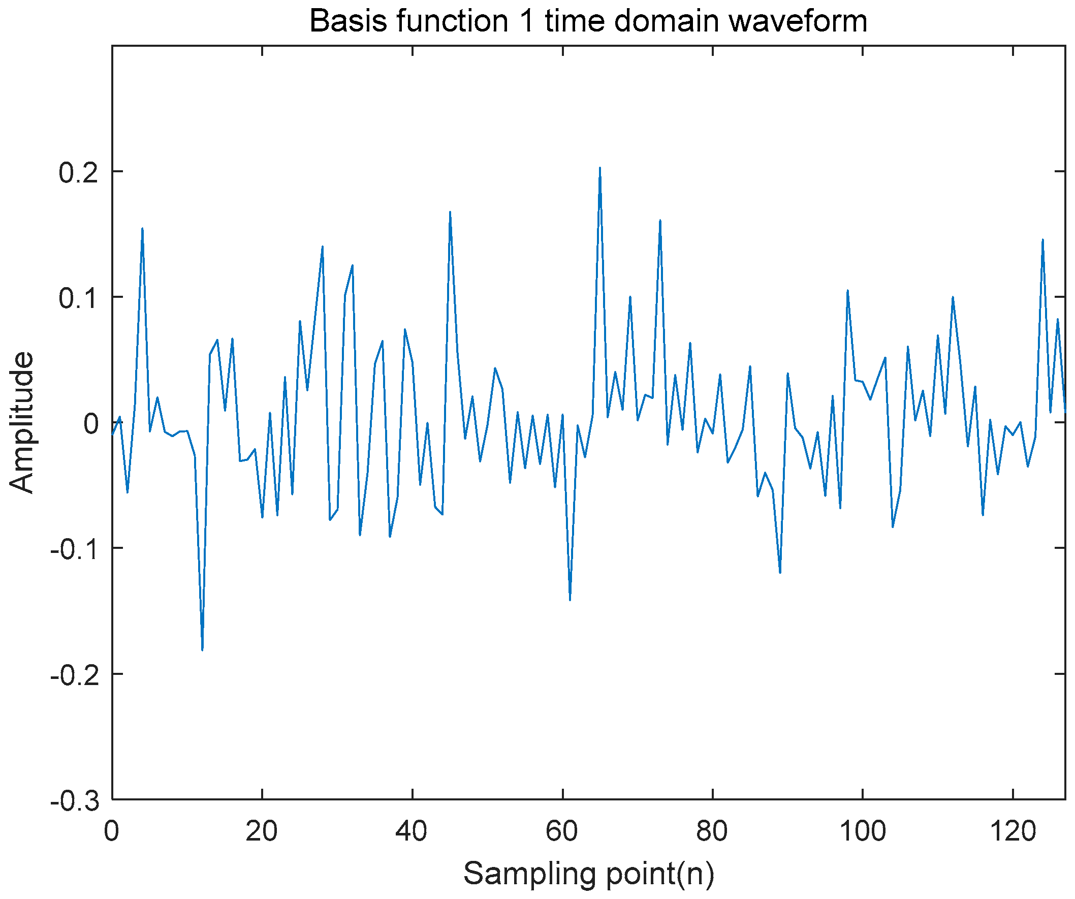
The Inverse Discrete Fourier Transform (IDFT) is subsequently applied to the frequency-domain basis function to generate the corresponding time-domain basis function sequence. This transformation facilitates the conversion of the designed frequency-domain representation into a time-domain waveform suitable for transmission.
The generated time-domain basis function is stored for reuse, provided that the external environment remains unchanged. This storage capability enables efficient reuse of the waveform without repeated computation, and facilitates further modification and dynamic adjustment of the amplitude, power, and phase of the time-domain basis function. Additionally, it supports subsequent modulation processes and enables flexible control of the data transmission rate.
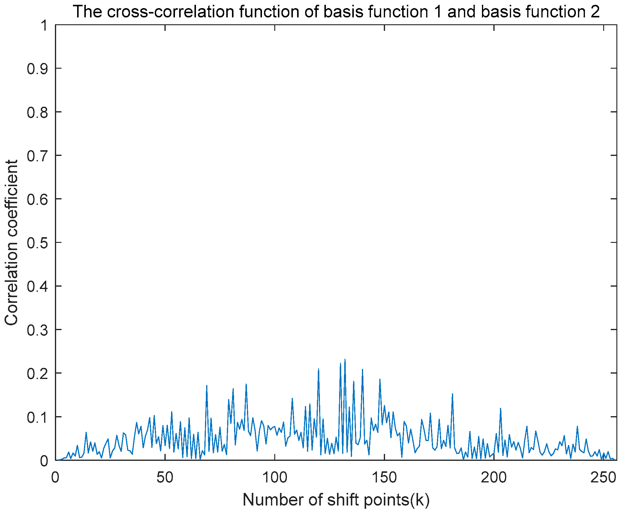
Suppose that the time domain basis functions generated by two different random phases are
and
respectively, and the cross-correlation function can be obtained by the definition of the cross-correlation function
where
is the relative time shift between two different time-domain basis function.
Based on the definition of the autocorrelation function, the autocorrelation of the time-domain basis function can be expressed as follows:
When
, the maximum value of the autocorrelation function
.
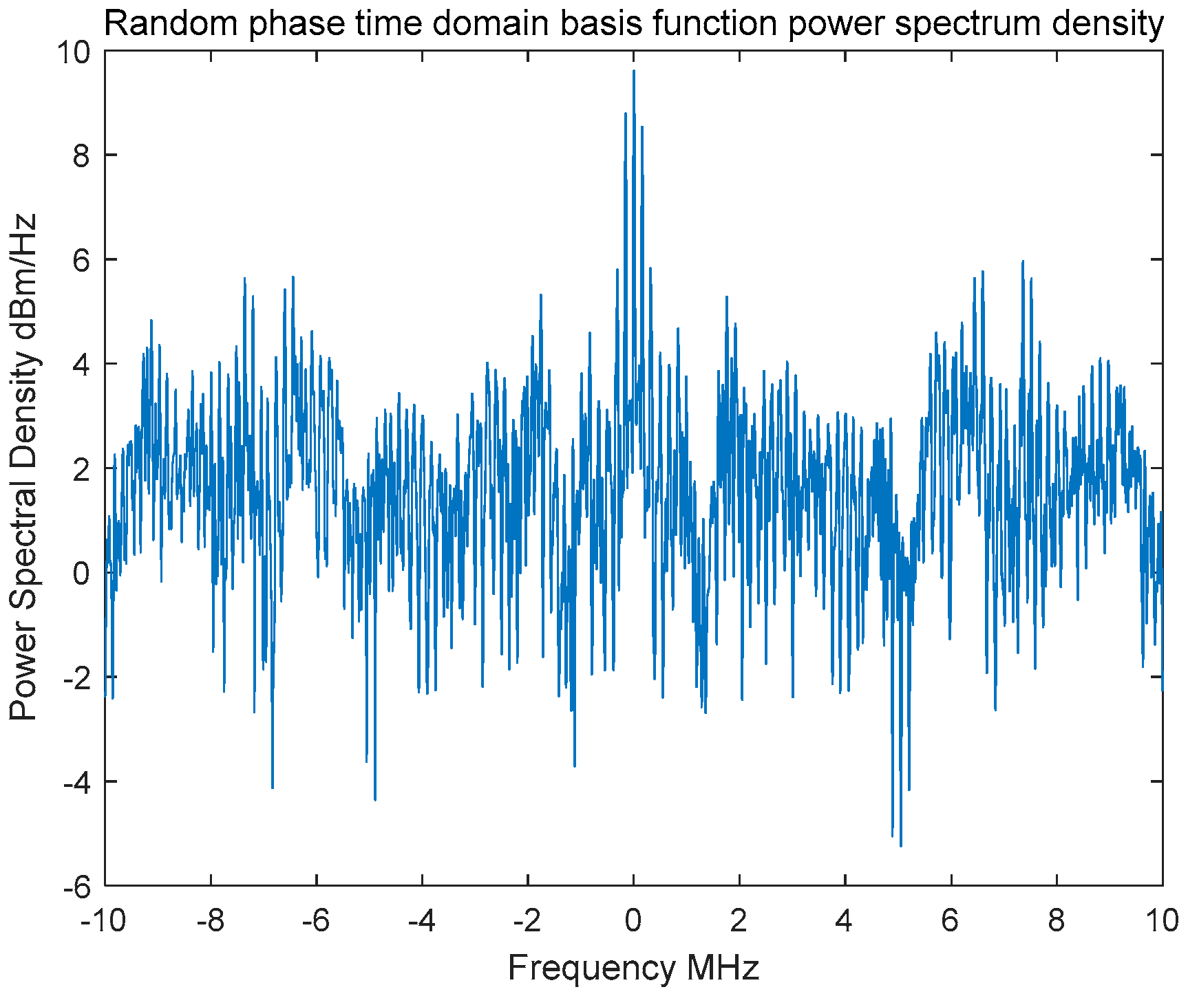
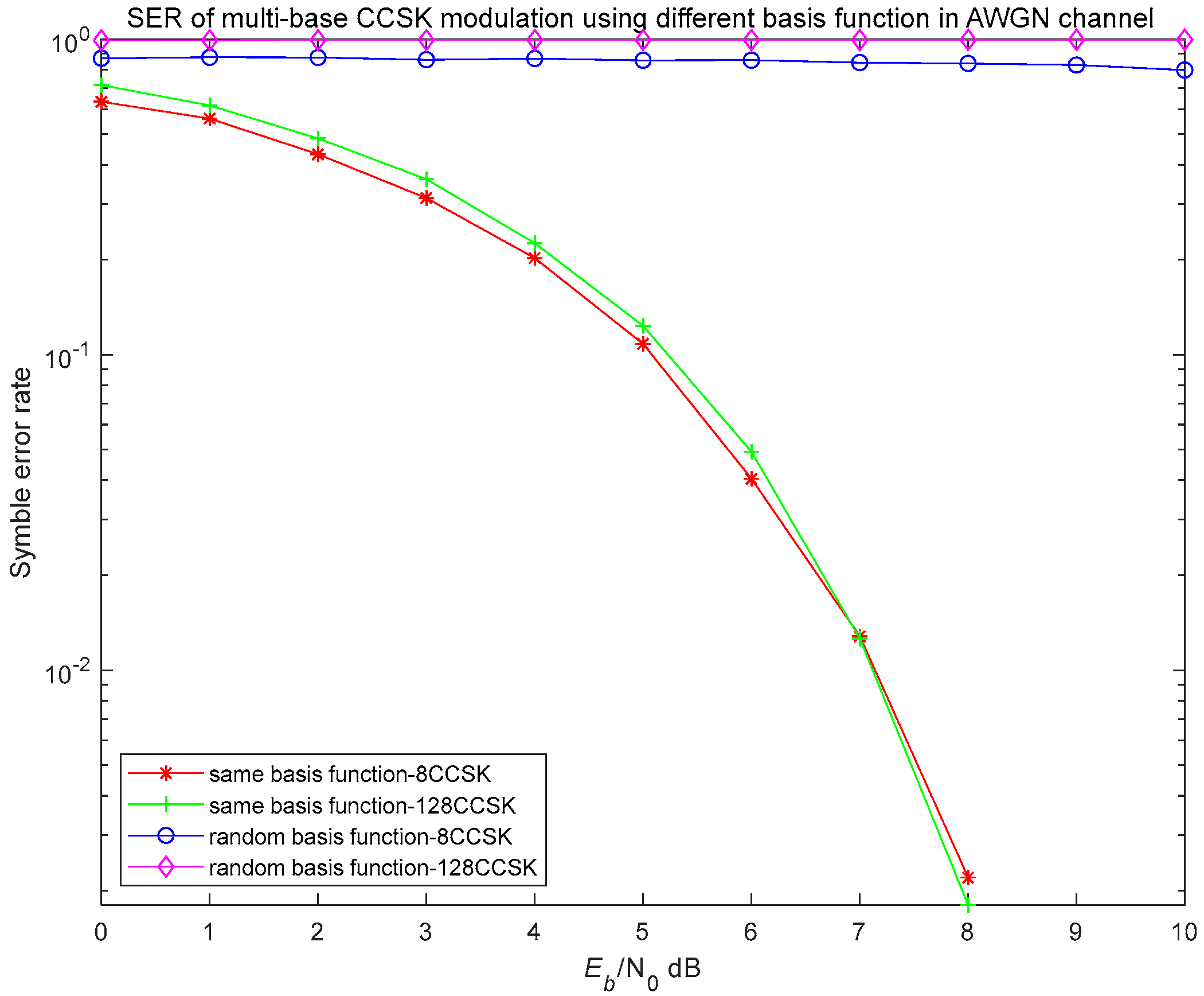
Based on the multistage shift register, two distinct pairs of
-sequences are generated using two different primitive polynomials and initial states, as determined by the previously described formula. From each interval, 3 consecutive bits are extracted and mapped to one of 8 distinct random phase mapping points. A total of 128 random phases are selected in this manner to construct the random phase matrix.
The above formula outlines a pseudorandom sequence generation process based on a primitive polynomial and a shift register, where specifies the register bits involved in determining the output, and represents the initial state of the register. The sequence is generated by cyclically shifting the register and extracting values at defined intervals, which are subsequently mapped to corresponding random phase values.
2.5. Modulation and Demodulation of NRPCS
This section focuses on transferring the signal from the time domain to the frequency domain to enable efficient data transmission and processing.
While traditional communication systems typically employ carrier modulation, the NRPCS achieves modulation through waveform modulation, specifically by transforming the generated time-domain basis functions. The modulation techniques used in noise-like communication systems primarily include bipolar modulation and orthogonal modulation. An enhanced version of Cyclic Code Shift Keying (CCSK) modulation, which builds upon these two methods, is adopted to improve system performance.
CCSK modulation transmits data by cyclically shifting a basis function waveform that possesses favorable periodic autocorrelation properties. Let the time-domain basis function sequence of length
be defined as follows:
The corresponding cyclic shift sequence can be expressed as:
Each sequence can represent a data information,
is generally a multiple of 2, so
elements can represent at most
bits of data information. For example, if the sequence length
and the modulation order
is 32, the CCSK modulation mapping is shown in
Table 1.
Multi-base CCSK modulation imposes stringent requirements on synchronization. In practical applications, correlation operations are typically employed during demodulation to detect correlation peaks. However, if there is any delay in the occurrence of these peaks, their positions may be misidentified, potentially leading to demodulation errors.
Therefore, the sequence length
is generally set to be greater than the modulation order
, so that the number of cyclic shift elements is often greater than 1. As shown in
Table 2 is the CCSK modulation mapping mode with sequence length
and modulation order
. Cyclic shift every 4 code elements represent a data to be transferred.
A time-domain cyclic shift is mathematically equivalent to multiplication by a phase factor in the frequency domain. As illustrated in
Figure 4, CCSK modulation can also be implemented through frequency-domain multiplication.
CCSK modulation can be interpreted as a specialized form of spread spectrum communication that employs a coding-like approach to simultaneously achieve spectrum spreading and information transmission. Compared to binary Direct Sequence Spread Spectrum (DSSS), CCSK can achieve a data transmission rate that is times higher, where is the number of CCSK elements, given the same channel bandwidth and spreading code length.
The selection of the CCSK basis function is critical. To facilitate demodulation at the receiver, it is generally required that the main peak of the periodic autocorrelation function of the basis function is high, while the peak of the periodic cross-correlation function is low. These properties are essential for accurate demodulation and to support multiple access in the system.
Correlation-based demodulation is typically employed in CCSK systems. Two common implementation approaches include matched filtering and frequency-domain demodulation. The frequency-domain method transforms the time-domain convolution operation into a frequency-domain multiplication, offering significant advantages in terms of hardware efficiency and implementation complexity.
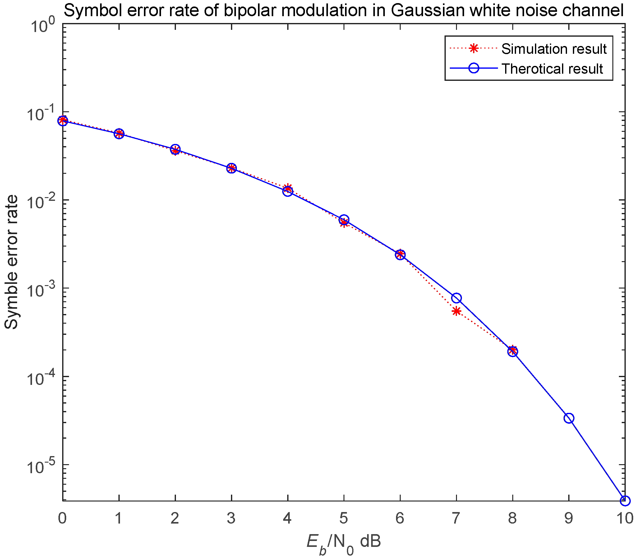
The CCSK correlation demodulation method is primarily based on the fundamental principle of correlation detection. For an -order CCSK system, both the receiver and transmitter generate the time-domain basis function and its cyclically shifted versions. Each of these is then multiplied and integrated with the received signal, followed by sampling at time .
Let the transmitted signal be denoted as
. Assuming the channel is an additive white Gaussian noise (AWGN) channel, the received signal can be expressed as
A set of received signals are first multiplied by the conjugate of the basis function and then integrated
where
is Gaussian white noise,
is the conjugate of the basis function, the two are independent of each other, the integral result is approximately 0, the above equation can be further simplified to
When the received signal has the same number of shifts as the multiplied basis function (
), the output is a constant; the output is approximately 0.
Sampling is conducted at time
. If a peak value is detected at this sampling point, it indicates that data corresponding to this specific path have been transmitted, thereby completing the demodulation process.
The correlation demodulation method for multi-base CCSK is consistent with demodulation techniques used in most modulation schemes. However, it presents certain challenges, notably the requirement for the receiver to reconstruct multiple fundamental modulation waveforms and the necessity for multiple multipliers and integrators to perform correlation operations. These factors result in increased structural complexity and hardware implementation difficulties. Consequently, practical implementations frequently adopt alternative demodulation techniques, such as the matched filter method derived from correlation demodulation and the frequency-domain demodulation method.
The matched filter approach effectively achieves CCSK demodulation by designing an appropriate matched filter at the receiver. The transmitted data are determined by evaluating the relative position of the output correlation peaks generated by the matched filter. Utilizing this approach, the demodulation structure transitions from employing multiple correlators to a single matched filter, significantly simplifying the hardware architecture. Additionally, the availability of FIR Intellectual Property (IP) cores in FPGA implementations further facilitates and simplifies hardware realization.
If the matched filter function is denoted by
, the duration of one code element is
, and the basis function is
, then the matched filter function can be expressed as follows
The received signal
is subsequently processed by the matched filter
, which is equivalent to performing a convolution operation between the signal and the filter, resulting in the filtered output.
Similar to correlation demodulation,
is approximately 0, so a set of matched filter output signals can be approximated as
The received signals represent cyclically shifted versions of the transmitted signal . Consequently, applying a matched filter to these signals generates correlation peaks. The demodulation process is completed by identifying the locations of these peaks, as each peak corresponds directly to the transmitted data.
The frequency-domain demodulation method operates under the same fundamental principle as the previously described approaches, but differs in that it transforms the signal processing from the time domain into the frequency domain. Specifically, the cyclic correlation operation between two discrete-time signals can be implemented efficiently by frequency-domain multiplication.
It is evident that correlation and convolution operations can be considered equivalent under certain conditions. By applying the Discrete Fourier Transform (DFT) to both sides of the equation above, we obtain the following expression:
Therefore, the frequency-domain demodulation method significantly simplifies the complexity of the system by converting intricate correlation and convolution operations into simpler multiplication operations. Specifically, the received signal is initially transformed into the frequency domain using a Fast Fourier Transform (FFT). Subsequently, the conjugate of the base sequence is also converted to the frequency domain through FFT, after which it is multiplied with the frequency-domain representation of the received signal. The resulting product is then transformed back into the time domain using the Inverse Fast Fourier Transform (IFFT) to identify the correlation peak. Finally, the transmitted data can be recovered by comparing the detected peak position with a predefined reference position.


