1. Introduction
The detector plays a crucial role in the detection and control of terminal damage within weapon systems, directly influencing the effectiveness of the weapon system [
1]. The radio detector, characterized by its simple structure, superior precision in ranging, and capability to effectively engage both aerial and ground targets, has been widely used at the present stage [
2]. In the modern battlefield, the electromagnetic environment is becoming increasingly complex, posing significant challenges for radio detectors to contend with many electromagnetic interferences. In particular, the repeater deception jamming, which is implemented by the fourth-generation jammer based on the digital radio frequency memory (DRFM) technology, can easily make the radio detector lose efficacy. Therefore, it is imperative to investigate and enhance the resistance of radio detectors against such jamming techniques, thereby improving their capability to withstand information interference.
In recent years, scholars have conducted extensive research on the anti-information interference of the radio detector [
3,
4,
5,
6], which can be categorized into multi-mode anti-interference based on information fusion and single-mode anti-interference based on the radio signal. The multi-mode anti-interference approach primarily integrates radio detection with other proximity detection technologies and uses multiple sensors to analyze signals in different domains. The detonation signal can only be output when the target signals generated by different sensors achieve a match. Currently, the research mainly focuses on the multi-mode radio detector of “radio signals + laser signals” [
7,
8,
9,
10,
11]. The literature [
10,
11] proposed a composite detection technology combining laser and radio along with the initiation criterion for radio detectors. This approach effectively solved the problems of laser detection technology in resisting interference from clouds, smoke, rain and snow, and radio-transmitted deceptive jamming. It significantly improved the signal-to-noise ratio. Moreover, a prototype was established, and the effectiveness of the composite detection technology in anti-interference was validated. However, in engineering practice, the multi-mode radio detector necessitates the design of transceiver modules that support more than two distinct signal systems, which require a relatively large space. The constrained space within the radio detector has emerged as a critical limiting factor for advancing multi-mode radio detectors.
The single-mode anti-interference based on radio signal is generally divided into three directions:
signal parameter modulation anti-interference, ultra-wideband anti-interference, and low probability intercept anti-jamming. Regarding signal parameter modulation anti-interference direction, the literature [
12] proposed an anti-interference method for the pulse Doppler radio detector based on M-sequence pseudo-code phase modulation. The response expressions at all levels during the detection process of the radio detector were theoretically derived, and the anti-interference performance of the radio detector was quantified. However, calculating the height of the radio detector requires the use of pseudo-code sequence autocorrelation. Jammers can directly copy and forward signals without mastering the specific system (form) of radio detector signals. Therefore, it is challenging for the pseudo-code phase modulation method to counter the spoofing interference based on DRFM. The literature [
13,
14,
15,
16] introduced a frequency-hopping signal where the frequency points were modulated by a pseudo-random sequence within a specified range, resulting in a random frequency pattern. Nevertheless, the jammer based on DRFM can also detect the frequency of signals at a relatively fast speed. Moreover, the frequency-hopping range of the radio detector is limited and it is easy to be detected by the jammer. Consequently, using signal parameter hopping alone presents challenges in effectively countering transmitted deceptive jamming.
In the field of ultra-wideband anti-jamming, Yan et al. [
17] studied the anti-interference performance of ultra-wideband radio detectors. The signal-to-stem ratio gain of correlation reception in the presence of Gaussian white noise and sinusoidal interference was derived in detail, and the signal characteristic parameters that affect the anti-jamming ability of the UWB radio detector were obtained. The quantitative analysis and simulation results show that the UWB radio detector had good anti-jamming performance against noise and sine interference. However, due to the reliance on correlation detection for distance determination, UWB radio detectors exhibited relatively limited resistance to forwarding spoofing interference. Zhu et al. [
18] studied the intelligent power distribution method of carrier-free UWB radio detectors in different frequency bands to achieve low interception. However, given the wide operating frequency band of UWB detectors, they are susceptible to unintentional interference from any frequency point within the band. Therefore, while these detectors demonstrate superior anti-reconnaissance performance, their overall anti-interference capability remains relatively weak [
19].
The third direction is low interception anti-interference. Given that the jammer first intercepts the signal, the low interception radio detector has significant anti-jamming potential. The low intercept radio detector encompasses three research directions: signal energy detection low intercept, parameter measurement low intercept, and spatial low intercept. According to the literature [
20,
21,
22], when the radio frequency signal approaches the resonance frequencies of water molecules and oxygen molecules in the atmosphere, the energy of the radio frequency signal will be absorbed, thereby reducing its detectability. By selecting the detection signal frequency of the radio detector in the frequency band with greater signal attenuation, the low probability of intercept performance of the radio detector can be improved. It should be noted that, with the rapid development of radio frequency components, modern jammers are now equipped with high-sensitivity receiving systems. In the presence of a sensitivity jammer, it is challenging for radio detectors to achieve low interception of detector signal energy detection. At the same time, the jammer can measure the frequency and other parameters of the radio detector signal quickly and with high precision. Therefore, it is difficult for radio detectors to achieve low interception when measuring signal parameters. This paper addresses this issue by focusing on airspace low intercept techniques and employing advanced signal design technologies to overcome the associated difficulties. Consequently, the low intercept and anti-jamming objectives for radio detectors are realized.
According to the above analysis, the radio detector has a broad application prospect in airspace low interception. From the perspective of information theory, the low interception radio detector ensures that the adversary acquires minimal information from its signal and beam, that is, the low entropy radio detector. Therefore, the concept of beam entropy is proposed in this paper to guide the design of a low intercept radio detector. Based on the characteristics of an S-shaped beam pattern in the frequency diverse array (FDA), we investigate the design of a low intercept spot-shaped beam from the perspective of FDA. By rapidly attenuating the amplitude of the wave crest in a small area (), the frequency offset setting formula of each array element is derived using the multiple-input multiple-output (MIMO) beam pattern function. The design principle of a low interception point beam based on the formula of array element frequency offset is obtained. The FDA-MIMO array can synthesize energy-concentrated spot beams in space, significantly improving the spatial low intercept performance of radio short-range detectors. Furthermore, the principle of point-beam design proposed in this paper provides theoretical support for point-beam design and guides the development of low intercept beam designs for radio detectors based on FDA-MIMO technology, thereby reducing the likelihood of interception by jammer reconnaissance.
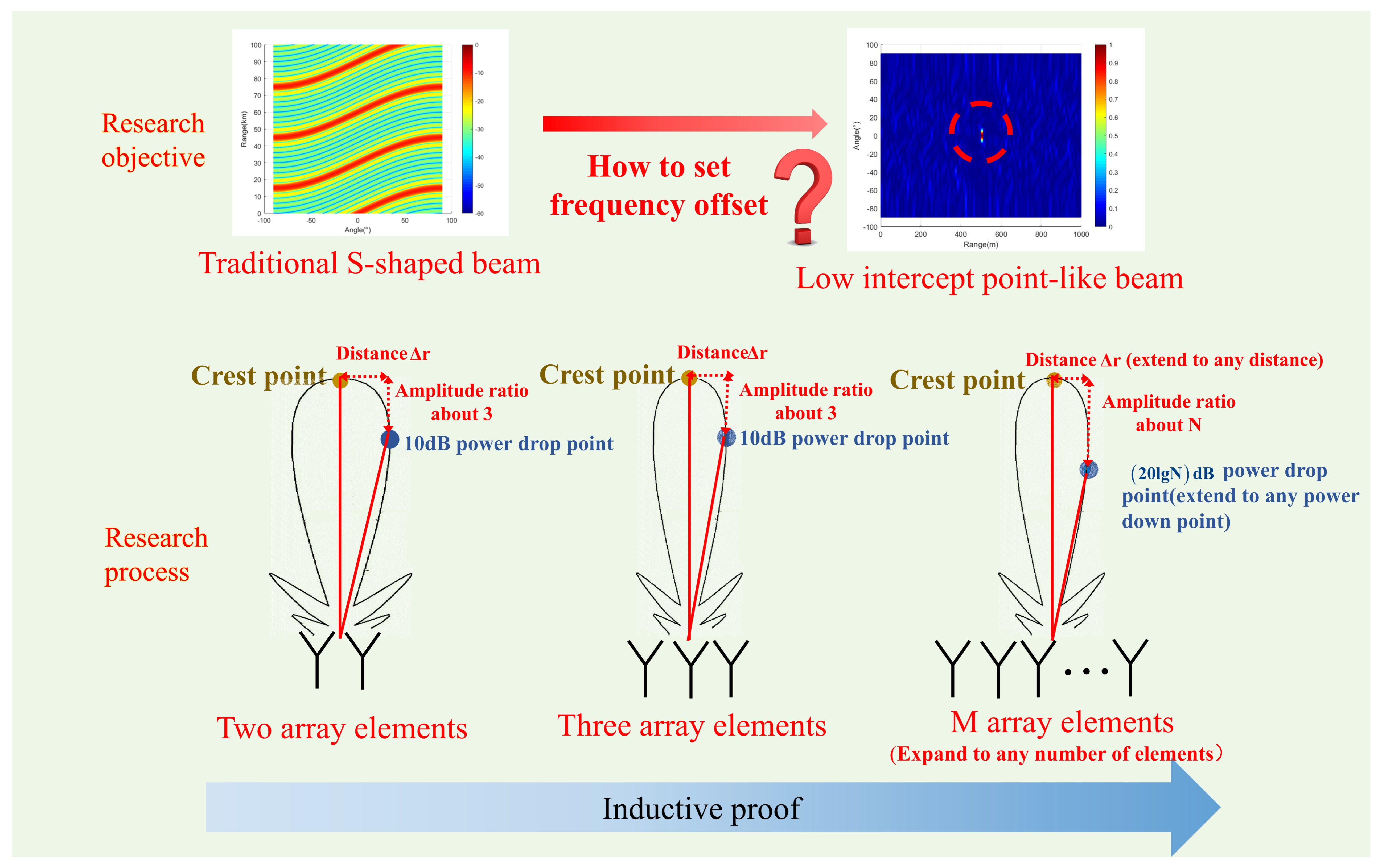
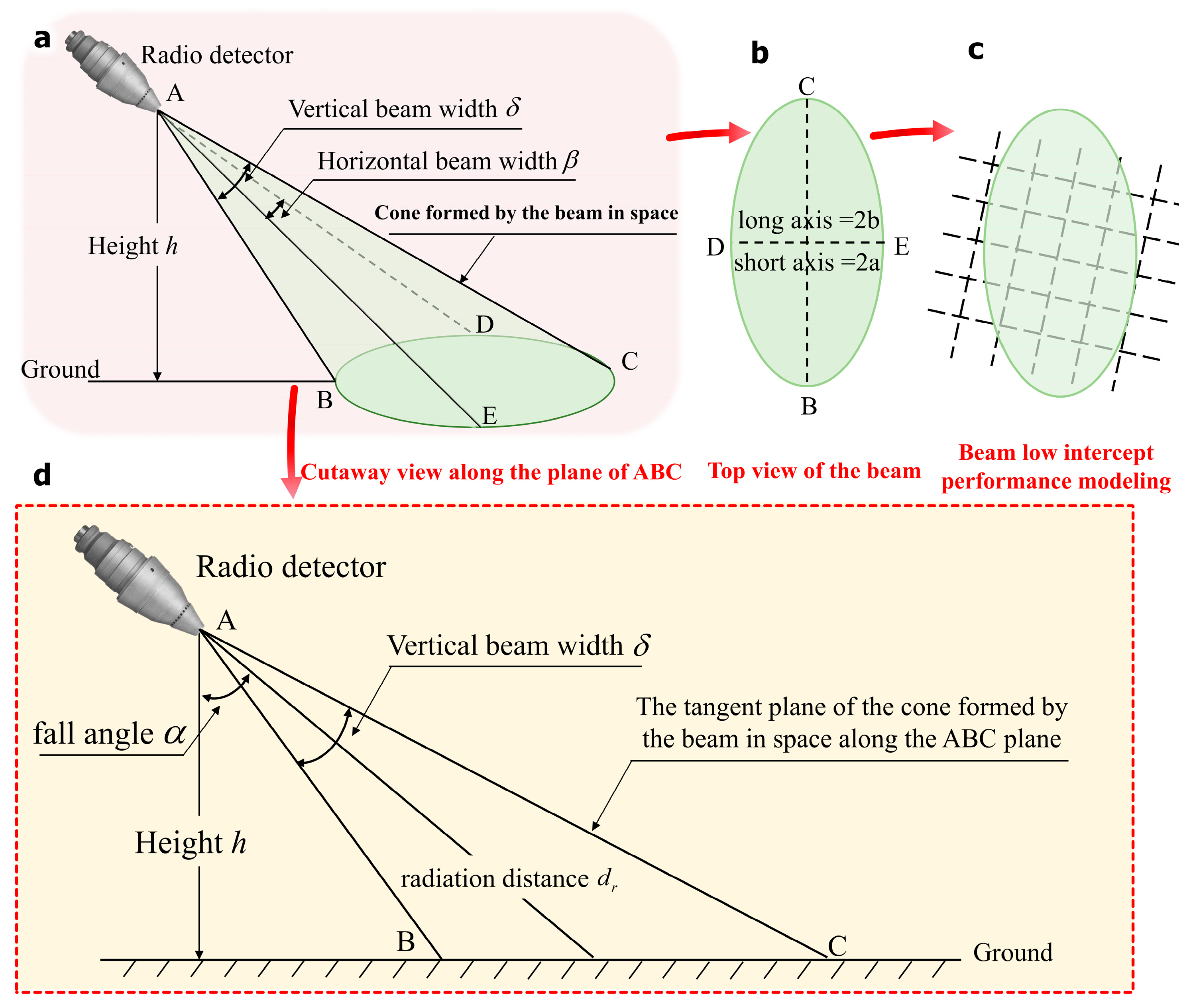
The logic diagram for writing the introduction of this paper is shown in
Figure 1. The contributions of this study are as follows.
From the point of view of information theory, this paper puts forward a principle and method that can guide the design of a low intercept beam of the radio detector using the principle and idea of entropy.
Furthermore, using entropy theory and FDA theory, the optimal convergence design of the FDA-MIMO low intercept point-like beam with an array frequency offset setting formula as the core is completed.
It should be noted that this paper does not focus on the anti-interference capabilities of radio detectors. Instead, it aims to design low intercept beams for radio detectors to minimize the enemy’s acquisition of our signal parameter information. The simulation results of the proposed method in an ideal scenario are shown in
Section 5. When considering the real-world operating conditions of radio detectors, noise and interference can occur during beam propagation. This results in the enemy receiving a weaker signal, thereby obtaining less signal information from us. Such a situation is more conducive to achieving our objective of low interception and reduces the probability of enemy detection.
This paper is organized as follows.
Section 2 presents the evaluation parameter design of low intercept performance based on entropy theory.
Section 3 introduces the basic theory of FDA.
Section 4 derives the formula for the design principle of a low intercept point-like beam.
Section 5 provides simulations and discussions on the signal design principle proposed in this paper.
Section 6 is the conclusion.
2. Evaluation Parameter Design of Low Intercept Performance Based on Entropy Theory
The evaluation parameters of low intercept performance are crucial for guiding the design of radio detectors. Numerous evaluation indexes of low intercept of radio detectors have been proposed, but no consensus has been reached. Rhee et al. [
23] proposed evaluation indexes such as frequency entropy, frequency level, and frequency hopping. Wu et al. [
24] selected parameters (e.g., broadband width product, signal complexity, peak power, minimum dwell time, sidelobe size, and beamwidth) and used the improved G-GIFSS algorithm to evaluate the low interception performance of the radio detector. Despite their comprehensiveness, these methods require extensive parameter calculations and thus fail to meet the requirement for concise computation. Chen et al. [
25] proposed that the transmitting power of the signal can serve as an evaluation parameter for low intercept probability. They argued that the lower the transmitting power correlates with a reduced likelihood of interception. However, this method is limited and may introduce subjectivity, making it challenging to objectively and comprehensively assess the low intercept performance of radio detectors. Therefore, establishing a simple, objective, and fair evaluation index of the low intercept performance is crucial, effectively guiding the design of the low intercept beam.
Interception refers to the detection of radio signals by enemy jammers, which allows the adversary to acquire our information. A low interception beam minimizes the amount of information that can be obtained by the enemy. Jia and Dao from the Army Engineering University proposed approximate entropy to measure the complexity of chaotic sequences. Approximate entropy is used to evaluate the jump performance of signal parameters modulated by chaotic sequence [
14,
15]. Subsequently, the low interception performance of the signal is evaluated. However, this method evaluates approximate entropy solely based on signal parameters and does not account for the convergence of the beam in space or the low interception performance in the beam’s airspace.
Therefore, from the perspective of information acquisition and confrontation between radio detectors and intercepting receivers, this paper defines beam entropy to quantitatively evaluate the low intercept performance of the beam. Entropy is a fundamental parameter in thermodynamics that characterizes the state of matter, with its physical meaning quantifying the degree of disorder within a system. Information entropy is a basic concept of information theory, which describes the uncertainty of various possible events occurring in an information source. Information entropy was first proposed by Shannon [
26].
Information entropy addresses the problem of quantitatively measuring information. The formula for calculating information entropy is as follows:
where
represents the probability of event
i occurring in the event set;
n indicates the total number of events in the event set. The logarithmic function is based on 2. In this paper, beam entropy is defined to quantitatively evaluate the low intercept performance of a beam. The beam entropy can be expressed by Equation (2):
where
r is the beam detection distance at any point
within the beam detection range;
is the beam detection angle at any point
within the beam detection range;
.
represents the beam amplitude of a certain
in the beam detection range. The unit of
is bits. In theory, r and
are beam parameters and should be continuous parameters. However, radio signal processing equipment is mainly digital in engineering practice. Consequently, beam entropy is primarily achieved through the digitization and discretization of parameters. Therefore, Equation (2) in engineering practice can be rewritten as:
Beam entropy
is used to reflect the average information content of the beam. A lower beam entropy value indicates greater beam convergence, which enhances the low intercept performance of the beam. In the existing spatial beamforming technology, FDA-MIMO technology can form a narrow beam in both distance and beamwidth, resulting in lower beam entropy. Therefore, this paper employs FDA-MIMO technology to design a low intercept radio detector.
3. Basic Theory of FDA-MIMO
The concept of FDA was first proposed in the literature [
27,
28]. FDA introduces a frequency offset to each coherent signal’s center frequency, where the offset is significantly smaller than the center frequency itself. Although the center frequency of each signal radiated out is offset, the main frequency components remain overlapping. This approach differs from orthogonal frequency division multiplexing [
29] (OFDM) and MIMO required for frequency orthogonality. The physical characteristics of FDA are similar to those of phased arrays [
30].
Due to the unique S-shaped beam pattern of FDA, the concept of frequency array has attracted wide attention [
31,
32]. There are a large number of studies on FDA.
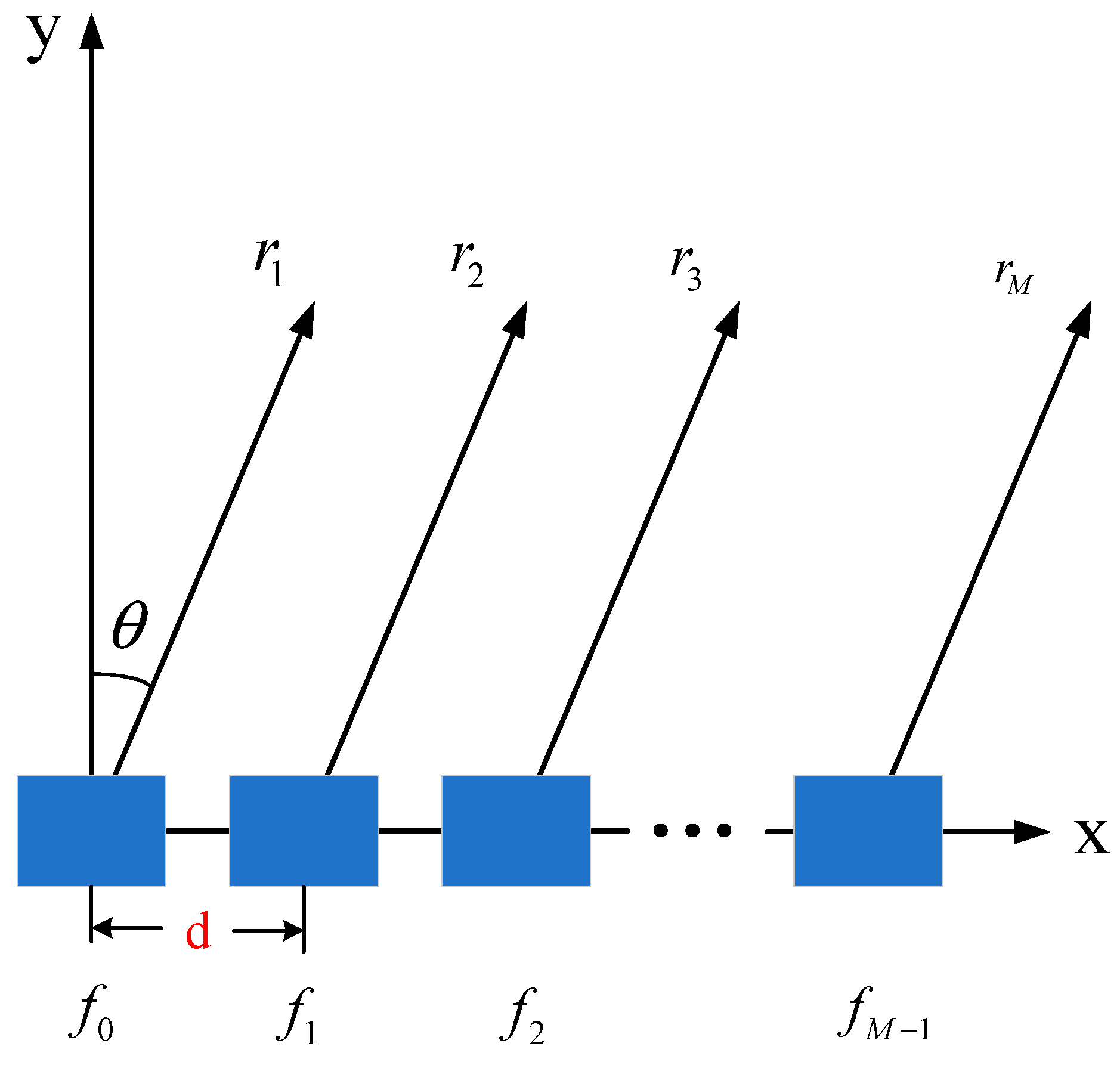
As shown in
Figure 2, FDA introduces a frequency offset that is significantly smaller than the center frequency to each coherent signal. The radiation frequency of the first array is
, the radiation frequency of the second array is
, and the radiation signal frequency of the
m-th array is:
where
is the center frequency of each coherent signal. In
Figure 2,
is the distance from the beam pointing position to the first array element (reference array element), and
is the distance from the beam pointing position to the second array element. Similarly,
is the distance from the beam pointing position to the
M-th array element.
If the frequency offset of each array is identical, the frequency of the radiation signal of the
M-th array is:
where
M represents the array sequence.
Taking a one-dimensional linear uniform array frequency array as an example, the uniformly weighted transmitting pattern is derived as follows.
The transmitted signal is assumed to be:
where
is the signal frequency of the
m-th array element.
Therefore, the FDA-MIMO beam direction diagram at
:
where
is the distance from the beam pointing position to the
m-th array;
c represents the speed of light. Since the arrays are evenly spaced, the following equation can be obtained:
where
is the distance from the beam pointing position to the first array element (reference array element);
m is the array number;
d is the array distance;
is the pointing angle of the expected beam. After combining Equations (4) and (8), Equation (7) can be further rewritten as:
where
is the frequency offset of the
m-th array relative to the reference array. In FDA-MIMO technology, the frequency offset of each array is much smaller than the base carrier frequency (the signal frequency of the reference array), namely
. As a result,
Therefore, Equation (9) can be simplified as:
If the frequency deviation increment of each array of FDA-MIMO is distributed evenly, namely
Then Equation (11) can be rewritten as:
If the module length of the beam function is only considered rather than the phase, then Equation (13) can be simplified as follows:
See
Appendix A for the specific derivation process from Equation (13) to Equation (14).
If the frequency deviation increment of each array element of FDA-MIMO changes irregularly, the beam function can be expressed as:
By analyzing Equations (13) and (15), it can be seen that FDA technology has the following characteristics:
As shown in
Figure 3, the orientation of the frequency array pattern will be affected by the frequency offset loaded.
The most important characteristic of the frequency array is that its array factor is range-dependent. Assuming
,
Figure 4 compares array orientation diagrams for a frequency array and a phased array. The array pattern of a phased array has no distance dependence, while the unique S-shaped array pattern of the frequency array is caused by its array factor
. The distance difference of this factor between
and
is
, where
is the signal wavelength. This indicates that the peaks of its array pattern are a function of
and
.
The colors in
Figure 2 and
Figure 3 represent the amplitude of the beam, with a color bar legend provided on the right side of each figure. Colors that appear closer to red indicate higher beam amplitudes. This visualization was performed using the MATLAB 2018b simulation software.
4. Design Principle of Low Intercept Point-Like Beam
According to the analysis in
Section 3, the beam of a radio signal is mainly characterized by a beam function. Therefore, the research on the design principle of a low intercept point-like beam should commence with an in-depth analysis of the beam function. Here, the beam function can be reformulated as follows:
According to Equation (16), once the basic carrier frequency and beam synthesis position are determined, the amplitude of the beam at different positions is influenced by the array spacing d and array frequency offset . Considering that, for any given FDA-MIMO system, the array spacing is not modifiable once designed, and it cannot be repeatedly designed and changed many times. Therefore, research on the design principles of low interception point-like beams mainly focuses on the influence of the frequency offset setting of each array element on beam synthesis.
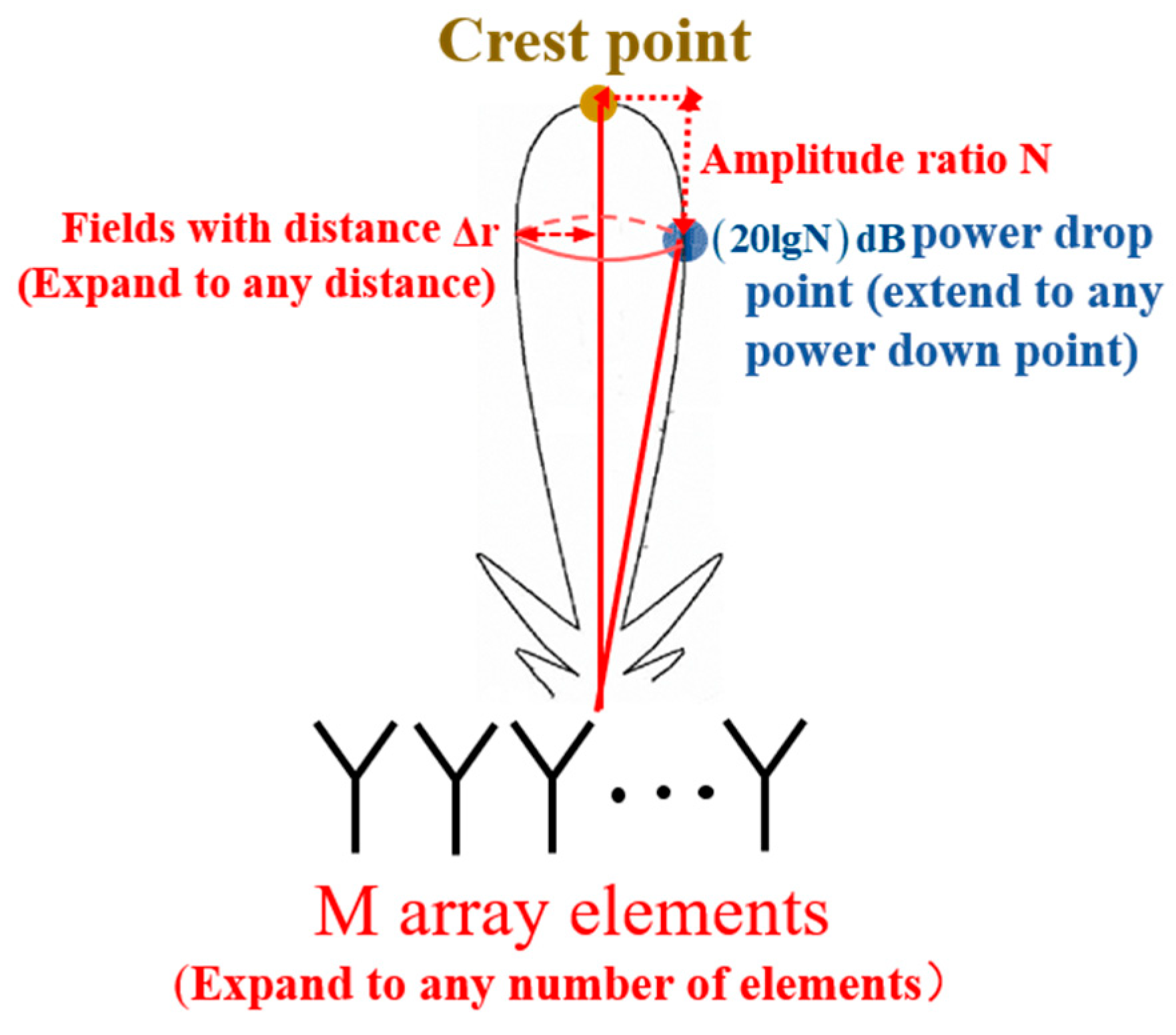
In this paper, we distinguish between ideal situations and situations with noise and interference and employ the principle of mathematical induction to systematically analyze the influence of frequency offset settings on the synthesis of point beams under the special case of
two array elements. Then, we extend our analysis to a configuration of
three array elements. Finally, we deduce the impact of frequency offset settings of each array element on the synthesis of point beams in the case of
M array elements. The logical diagram of the derivation and proof is shown in
Figure 5. Considering that the time variable does not influence the derivation of the entire formula within the beam function, the following formula derivation is carried out at the moment of t = 0. This assumption will not be repeated in the subsequent text.
At the same time, it is necessary to explain the scope of application of the derivation in this paper as follows:
- (1)
The derivations in this paper are mainly used for close range radio detection probes such as radio fuzes.
- (2)
Operating frequency: 1 GHz to 40 GHz.
- (3)
Operation area: radio signals are transmitted from the air to land.
- (4)
Propagation problem: Because the detection distance of radio fuzes is relatively close, and the use of radio fuzes is usually in an open field, the multipath effect is not obvious. Rain, water vapor, oxygen, etc., can attenuate radio signals. Therefore, the author improves the derivation of this paper from the perspective of signal-to-noise ratio, as detailed in
Section 4.2.
4.1. Low Intercept Point-Like Beam Design in Ideal Case
4.1.1. Case of Two Array Elements
Assuming that the wave crest point of FDA-MIMO is
H, then the beam amplitude of
H is:
Then, the beam amplitude at point
,
away from point
H, is:
Given that
is the 10 dB power drop point, and the distance
between
H and
is very close, the beam will approach the point beam. Therefore,
Equation (19) is simplified as,
In fact, the radio detector activates at the terminal phase of the projectile flight, and the angle between the projectile and the ground is usually large and approximately vertical. Therefore, the angle between the radio detection beam and the ground normal is very small, . Considering that the radio detector has a range of about 200 m and is very small, , , .
Therefore, exp(x) in Equation (21) can be applied to the first-order Talor expansion of the exponential function at
x = 0, i.e.,
Therefore, the first-order Talor expansion of Equation (21) at
x = 0 is:
In Equation (21)
. Therefore, the following equation can be obtained:
The value of
is sufficiently small that it can be considered negligible. Consequently, Equation (29) can be simplified to:
The frequency offset
can be obtained by simplifying Equation (30):
In the case of two array elements, when the frequency offset design is calculated according to Equation (31), FDA-MIMO can form a low interception point-like beam.
4.1.2. Case of Three Array Elements
Assuming that the wave crest point of FDA-MIMO is H, then the beam amplitude of H is:
Then, the beam amplitude at point
,
away from point
H, is:
We can reasonably assume that
is the 10 dB power drop point. Given that the distance
between point
H and point
is very small, then the beam will approach the point beam. Therefore,
Equation (34) is simplified as:
With reference to the approximation conditions of the two-element case, exp(
x) in Equation (36) can use the first-order Talor expansion of the exponential function at
x = 0. As a result, the first-order Talor expansion of Equation (36) at
x = 0 can be expressed as follows:
In Equation (37)
; therefore,
After substituting
from Equation (31) into Equation (38) yields, the following equation can be obtained:
It can be seen from Equation (39) that in, the case of three-element arrays, when the frequency offset design is calculated according to Equation (39), FDA-MIMO can form a low interception point-like beam.
4.1.3. Case of M Array Elements
Assuming that the wave crest point of FDA-MIMO is point
H, then the beam amplitude of point
H is:
Then, the beam amplitude at point
,
away from point
H, is:
In
Section 4.1 and
Section 4.2, it is assumed that point
is the 10 dB power decline point, which is extended to
, the power decline point in this section. Therefore,
With reference to the approximation conditions of the two-element case, exp(
x) in Equation (43) can use the first-order Talor expansion of exponential function at
x = 0, so the first-order Talor expansion of Equation (43) at
x = 0 is as follows:
Given that
in Equation (44),
By solving Equation (45), we can obtain:
After substituting Equation (47) into Equation (46), it can be obtained that:
Furthermore, if the distance between the peak point H and the power decline point is r (), Equation (48) needs to be integrated with as the principal element. However, when r is relatively large, the beam can no longer be approximated as a point source and falls outside the scope of this study. Therefore, this paper will no longer solve the frequency offset expression when the distance between two points is r.
4.2. Low Interception Point-Like Beam Design with Noise and Interference
In this section, the design principle of low interception point-like beam with noise and interference is mainly derived and the propagation of the beam in the Gaussian channel is analyzed. Considering the propagation of the beam in the Gaussian channel, the Shannon formula can accurately reflect the relationship between channel capacity, channel bandwidth, and signal-to-noise ratio. Shannon’s formula is shown in Equation (49).
where
C is the channel capacity.
B is the channel bandwidth.
S is the average power of the signal and
N is the average power of the noise.
S/
N is the signal-to-noise ratio. In the derivation of this section, the Shannon formula is used for reference, and Shannon weighting is carried out on the amplitude of the beam; the weight is
.
4.2.1. Case of Two Array Elements
When considering noise and interference, the amplitude of H point is weighted by Shannon:
Then, the beam amplitude of point
at a distance
to point H is:
Given that
is the 10 dB power drop point, and the distance
between
H and
is very close, the beam will approach the point beam. Therefore,
Equation (52) is simplified as:
Therefore,
It can be seen from Equation (54) that the subsequent derivation is the same as that in
Section 4.1.1. The author will not repeat; we can calculate the frequency offset
:
4.2.2. Case of M Array Elements
In the presence of noise and interference, assuming that the peak point of the FDA-MIMO received by the fuze jammer is still H point, then the H-point beam amplitude weighted by the signal-to-interference noise ratio is:
After the signal-to-interference noise ratio is weighted, the beam amplitude of the
point from the H point
is:
Given that
is the
power drop point, and the distance
between
H and
is very close, the beam will approach the point beam. Therefore,
With reference to the approximation conditions of the two-element case, exp(
x) in Equation (59) can use the first-order Talor expansion of exponential function at
x = 0, so the first-order Talor expansion of Equation (59) at
x = 0 is as follows:
Given that
in Equation (60),
By solving Equation (61), we can obtain:
After substituting Equation (63) into Equation (62), it can be obtained that:
By comparison with Equations (48) and (64), it can be seen that, in the process of formula derivation, the frequency offset setting formula for the optimal convergence of the FDA-MIMO spot beam is the same regardless of whether noise and external interference are considered, because, in the process of dividing the amplitude, the weight of the signal-to-noise ratio to the amplitude has been reduced in the numerator and denominator (as shown in Equation (64)). In fact, the beam peak H point and the power drop point are always in the same environment. The effect of SNR on H point and point is the same. Therefore, it is true and credible that the weight of the signal-to-noise ratio to the amplitude is canceled when the numerator and denominator are divided.
4.3. Physical Explanation of Point-Beam Design Principle and Related Inferences
Through the analysis of the FDA-MIMO beam function, the amplitude of the beam at different positions is influenced by the array spacing and the array frequency offset when the basic carrier frequency and the beam synthesis position are determined. Given the constraints imposed by the hardware system, the array spacing d cannot be modified or changed repeatedly. Therefore, research on the design principle of low interception point-like beams mainly focuses on the influence of the frequency offset setting of each array on the beam synthesis.
In the frequency offset setting of each array element, by setting the peak point
H and the 10 dB power drop point
in a relatively close range (
), the goal is to achieve a significant beam amplitude in a small vicinity around point
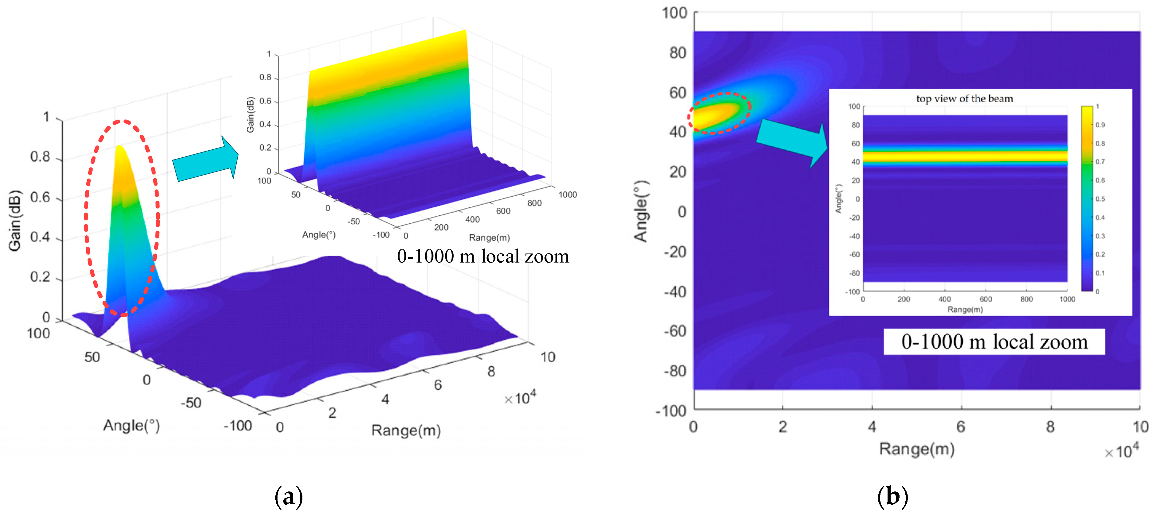
H while ensuring a rapid attenuation of the beam amplitude in other regions. Further, the beam function is used to calculate the frequency offset of each array element, thereby establishing the design principle of a low interception point-like beam. The schematic diagram of the low intercept point-like beam design principle is shown in
Figure 6.
Inference 1. The frequency offset of each FDA-MIMO array is gradually increasing.
Inference 2. Based on Equation (48), the frequency offset of each array element of FDA-MIMO forming a point beam has a frequency deviation fluctuation of 10%.
6. Conclusions
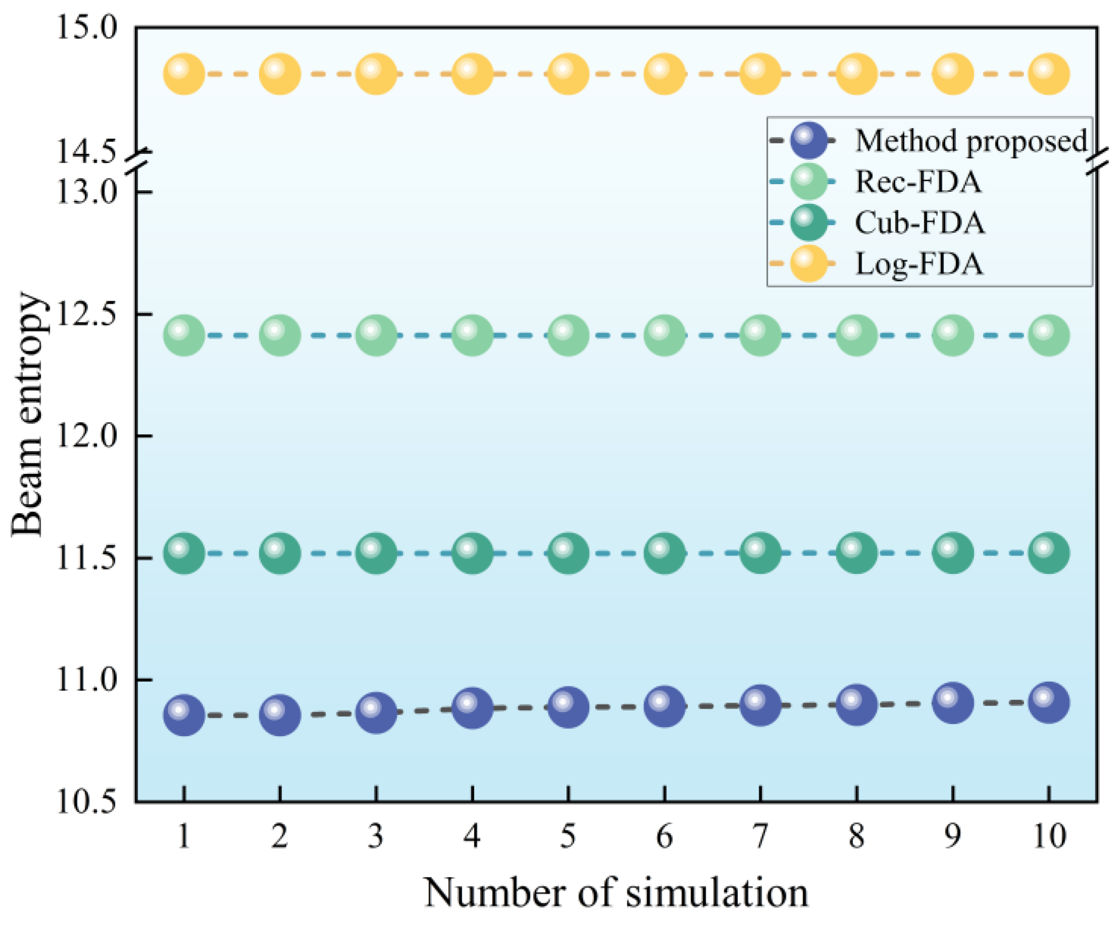
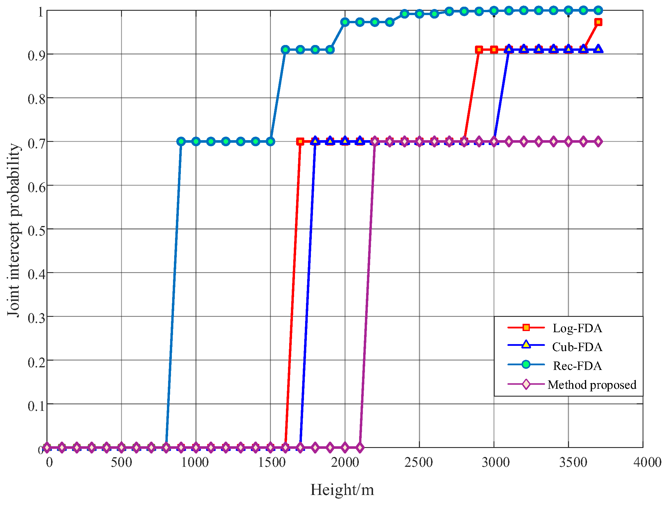
In this paper, the concept of beam entropy is proposed to guide the design of low intercept beams for radio detectors. Based on FDA-MIMO technology, the design principle of low interception optimal converging beam for radio detectors is presented. By strategically positioning the wave crest and power drop points within a relatively close range (), the beam amplitude in a small neighborhood with a radius of near the wave crest point is large, while the beam amplitude in other ranges is rapidly decreased. Furthermore, the beam function is used to calculate the frequency offset of each array element, leading to the development of a design principle centered on low interception point-like beams through this frequency offset setting method. By plotting the beam pattern, the point-like beam designed in this paper achieves a distance of 1 m and a beam width of 9 degrees. The performance of beam convergence is superior to the existing classical methods. The simulation of low interception performance based on beam entropy and spatial domain shows that the entropy of the designed beam reaches its minimum value. Additionally, the probability that the beam designed in this paper is intercepted within 2100 m from the ground is 0, which aligns well with the activation distance requirements of radio fuzes. In contrast, beams designed using existing classical methods exhibit higher entropy and inferior performance in low airspace acquisition. In summary, through rigorous formula derivation and beam simulation, the correctness of the design principle of the low interception point-like beam is verified. It provides theoretical support for the low intercept beam design of radio detectors based on FDA-MIMO. The optimal beam convergence method proposed in this paper can enhance the low intercept performance of the radio detector but also improve its anti-jamming capabilities. Moreover, the application of low interception point-beam optimal convergence design technology holds significant potential. The technology proposed in this paper has broad applications in radio fuze detection and low intercept directional communication for unmanned systems, including unmanned aerial vehicles and unmanned boats. However, the method proposed in this paper still faces the problems of a complex frequency offset calculation formula and large amounts of calculations. Therefore, in order to be widely used in practical scenarios as soon as possible, the frequency offset calculation formula should be further optimized to achieve a simple and fast calculation of point-like beam frequency offset.

