
A Study on the Evolution Laws of Entrainment Performances Using Different Mixer Structures of Ejectors


Abstract
1. Introduction
2. Ejector Design Model
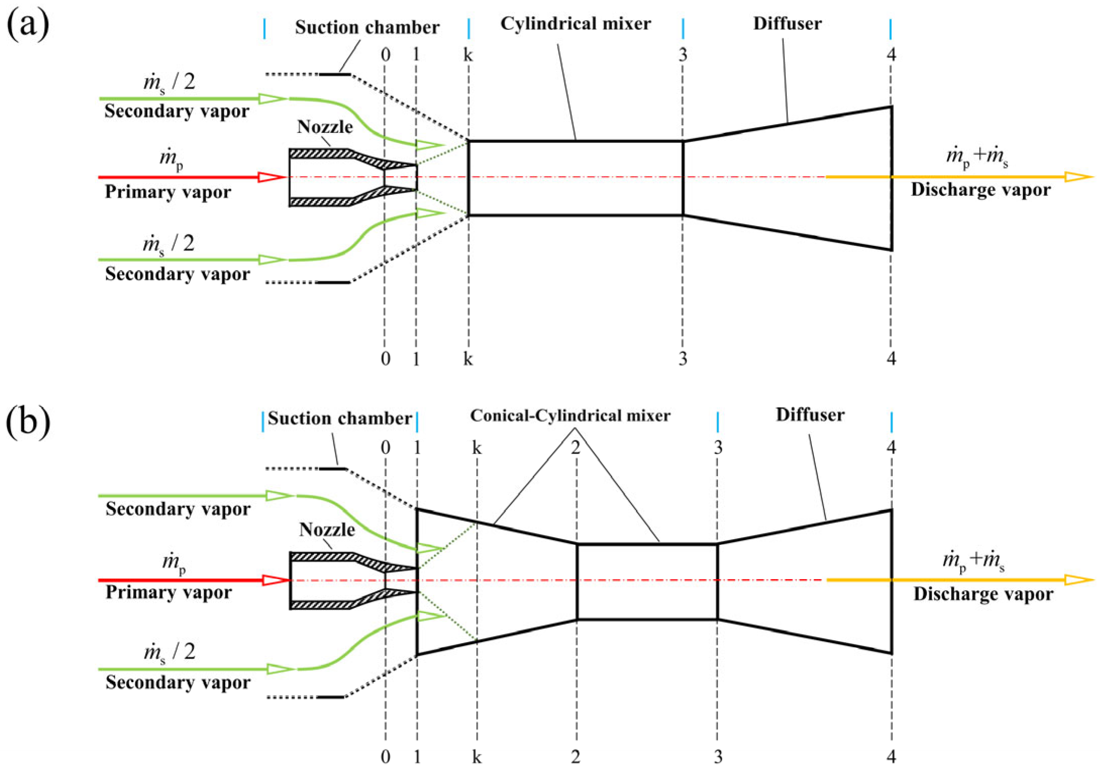
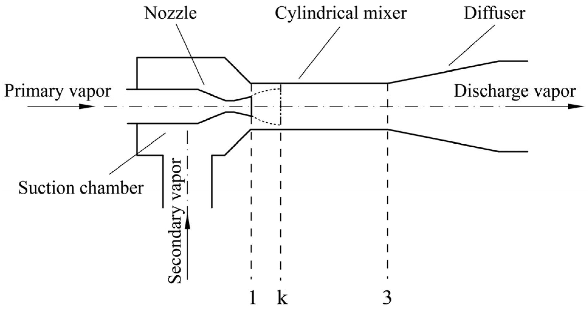
2.1. Model of Ejector with a Cylindrical Mixer
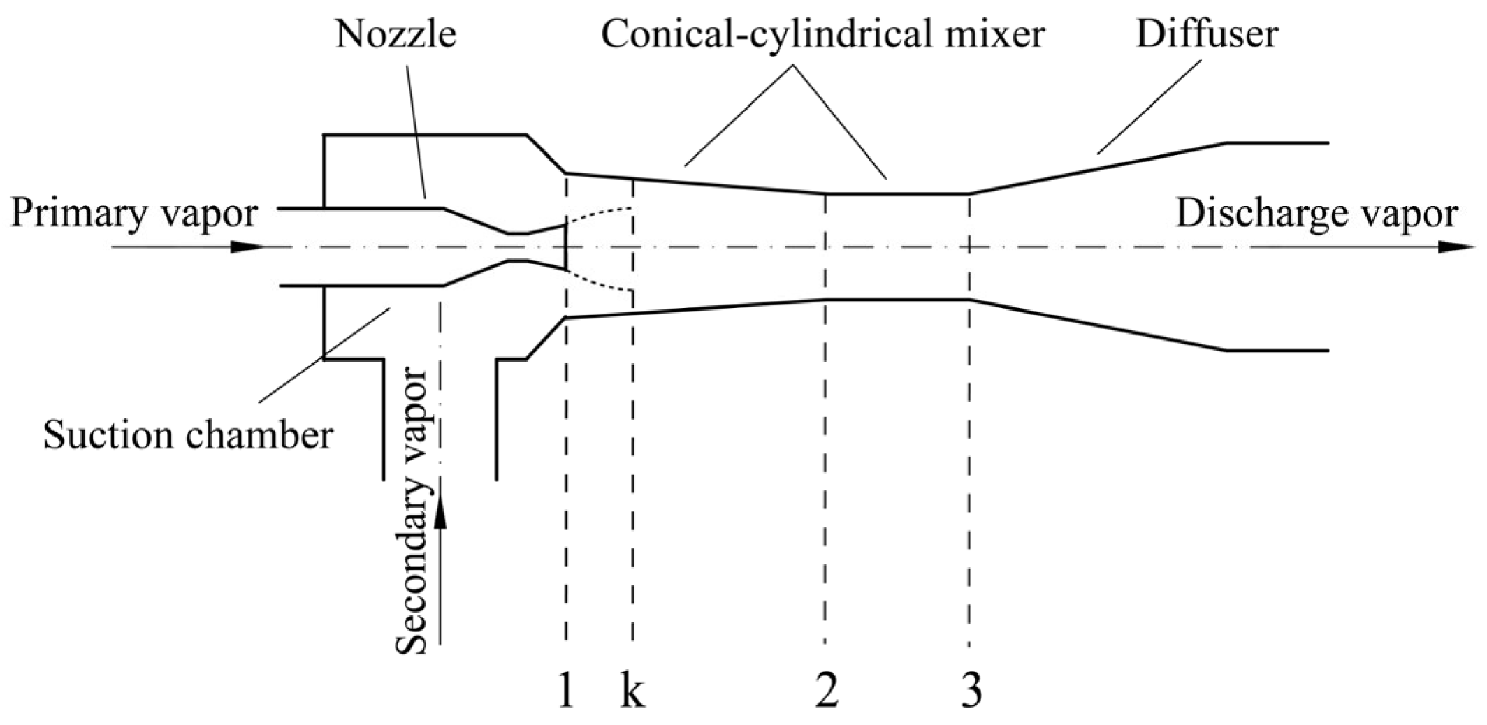
2.2. Model of Ejector with a Conical–Cylindrical Mixer
2.3. Ejector Design Steps
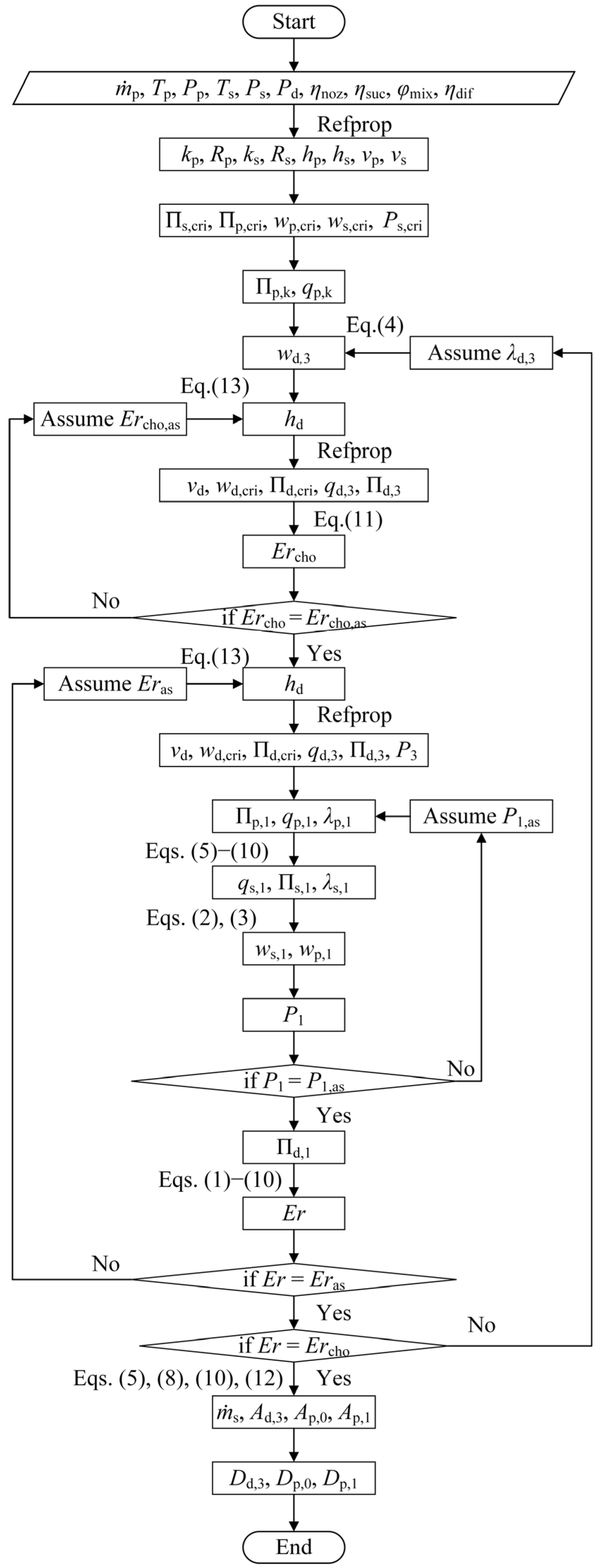
2.3.1. Design Calculation of the CME
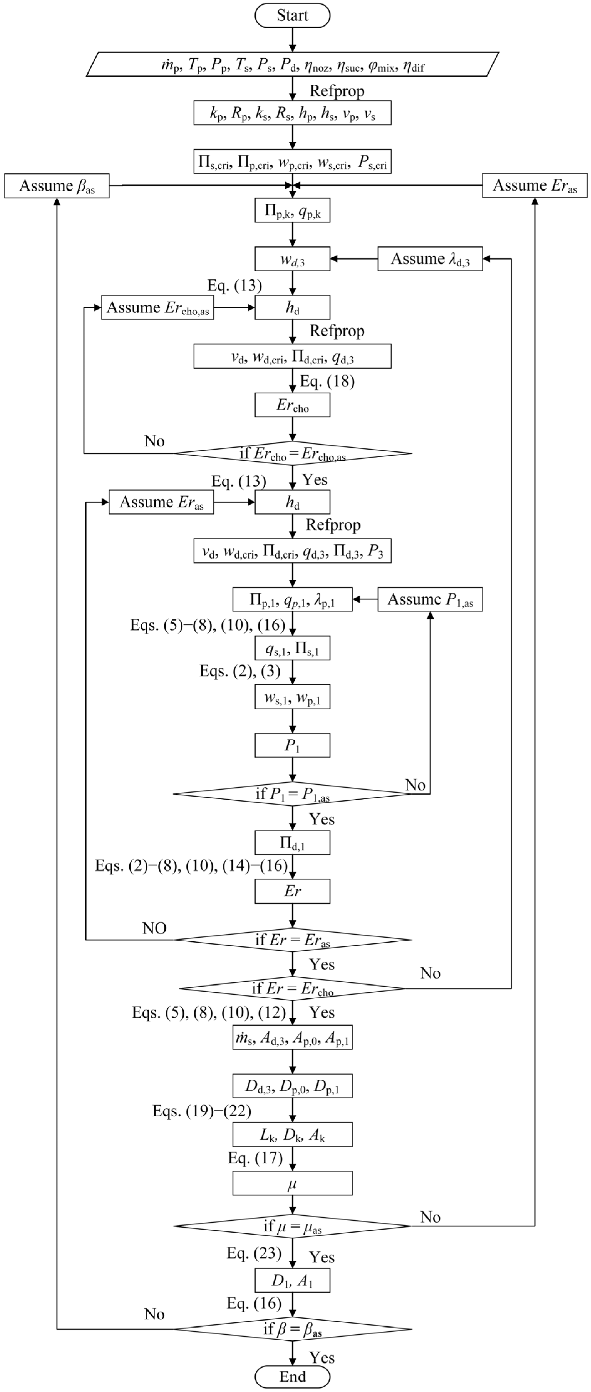
2.3.2. Design Calculation of the CCME
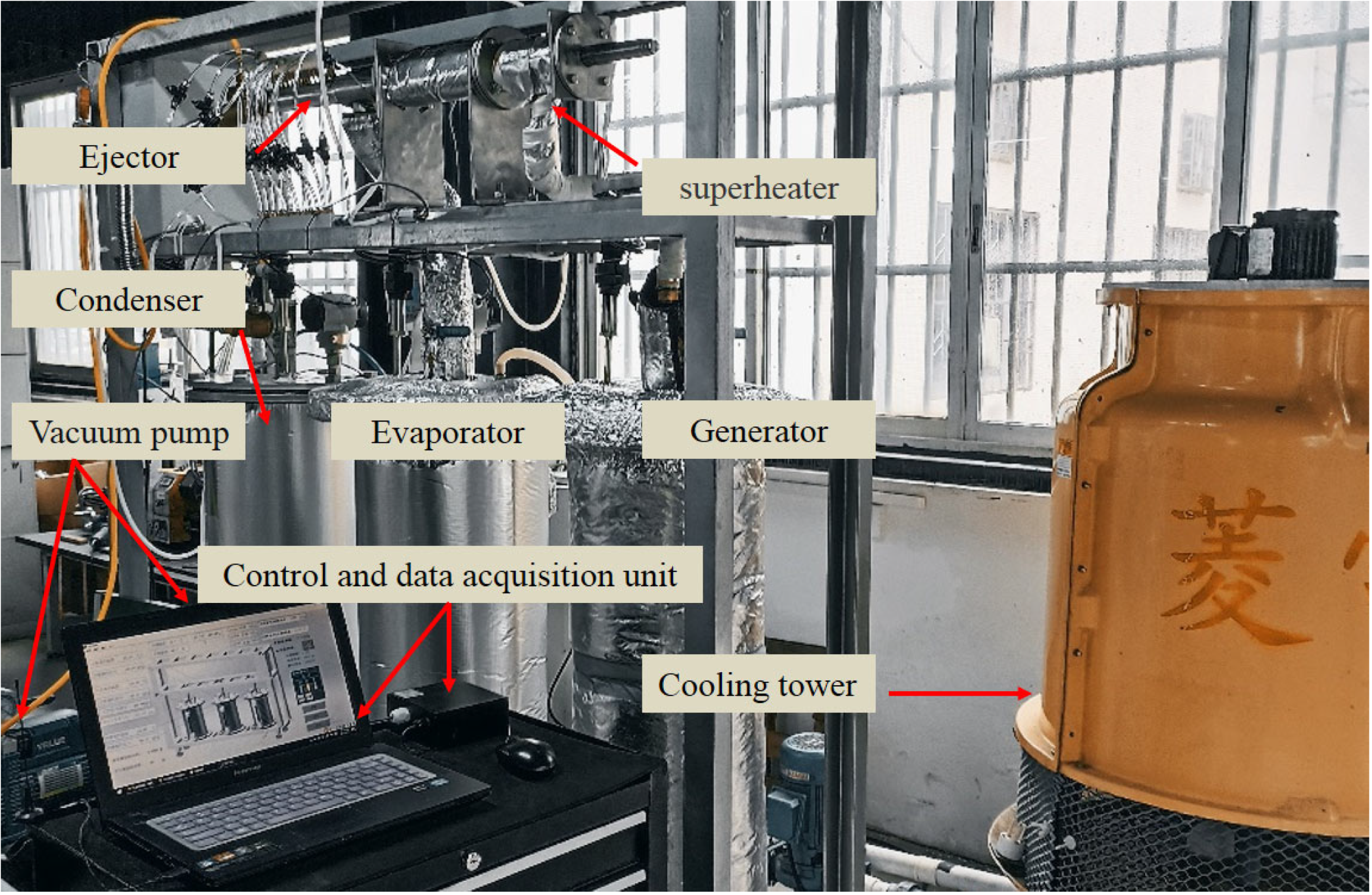
3. Experimental Validation
3.1. Experimental Materials
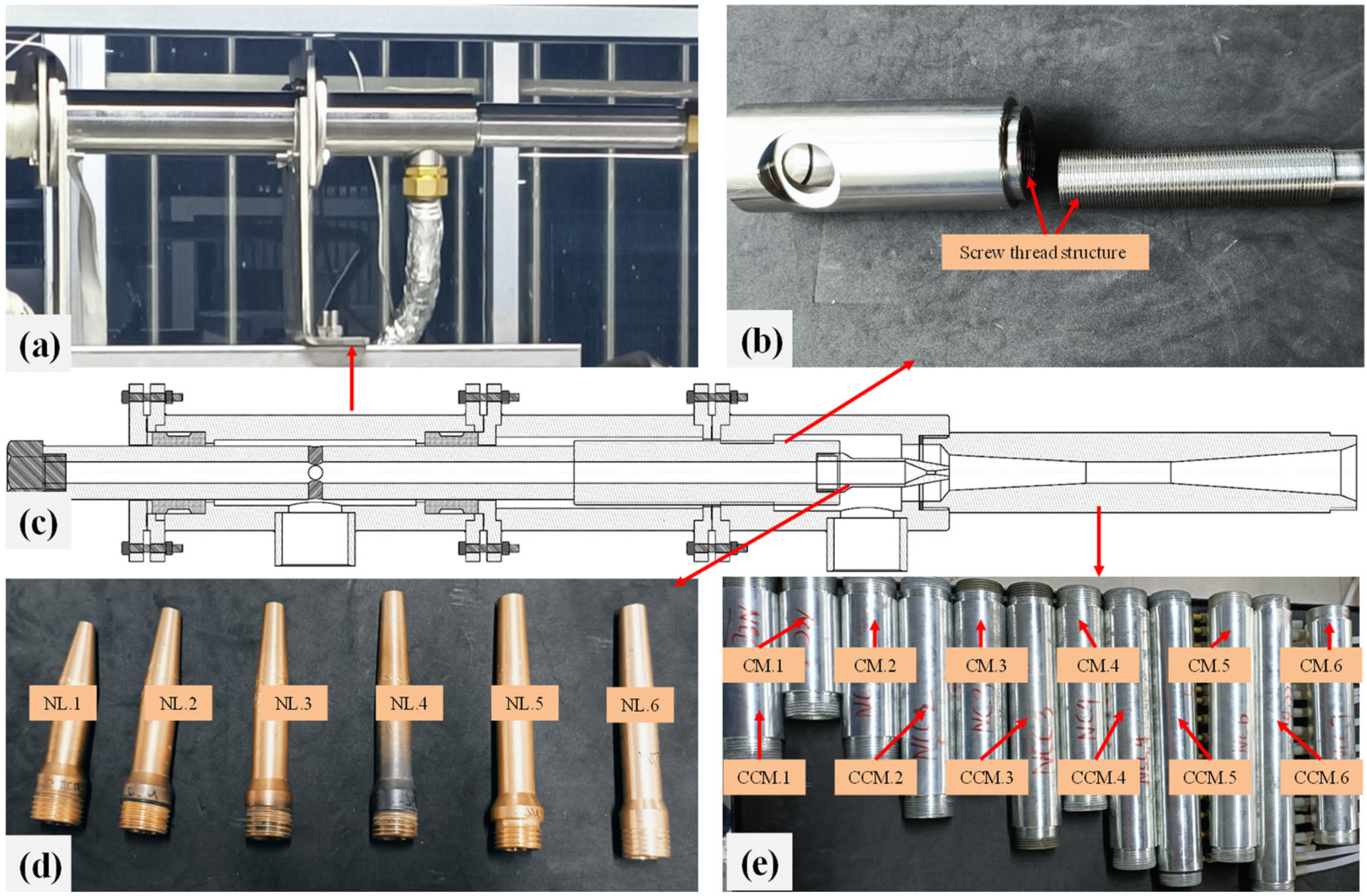
3.2. The Ejectors Used in the Experiment
3.3. Analysis of the Experimental Result
4. Analysis and Discussion
4.1. Evolution Laws of Entrainment Performances for the CME and CCME
4.2. The Mechanism of the Mixer Effecting the Entrainment Ratio
4.2.1. Distribution Characteristics of the Entropy Generation Rates in the CME and CCME
4.2.2. Distribution Characteristics of PLP and EGRP in the Mixers and Diffusers of the CME and CCME
4.2.3. Effect of Compression Ratio on the Total Entropy Generation Rate in the CME and CCME
4.2.4. Mechanism of the Difference in EGRP in the CCM and CM
5. Conclusions
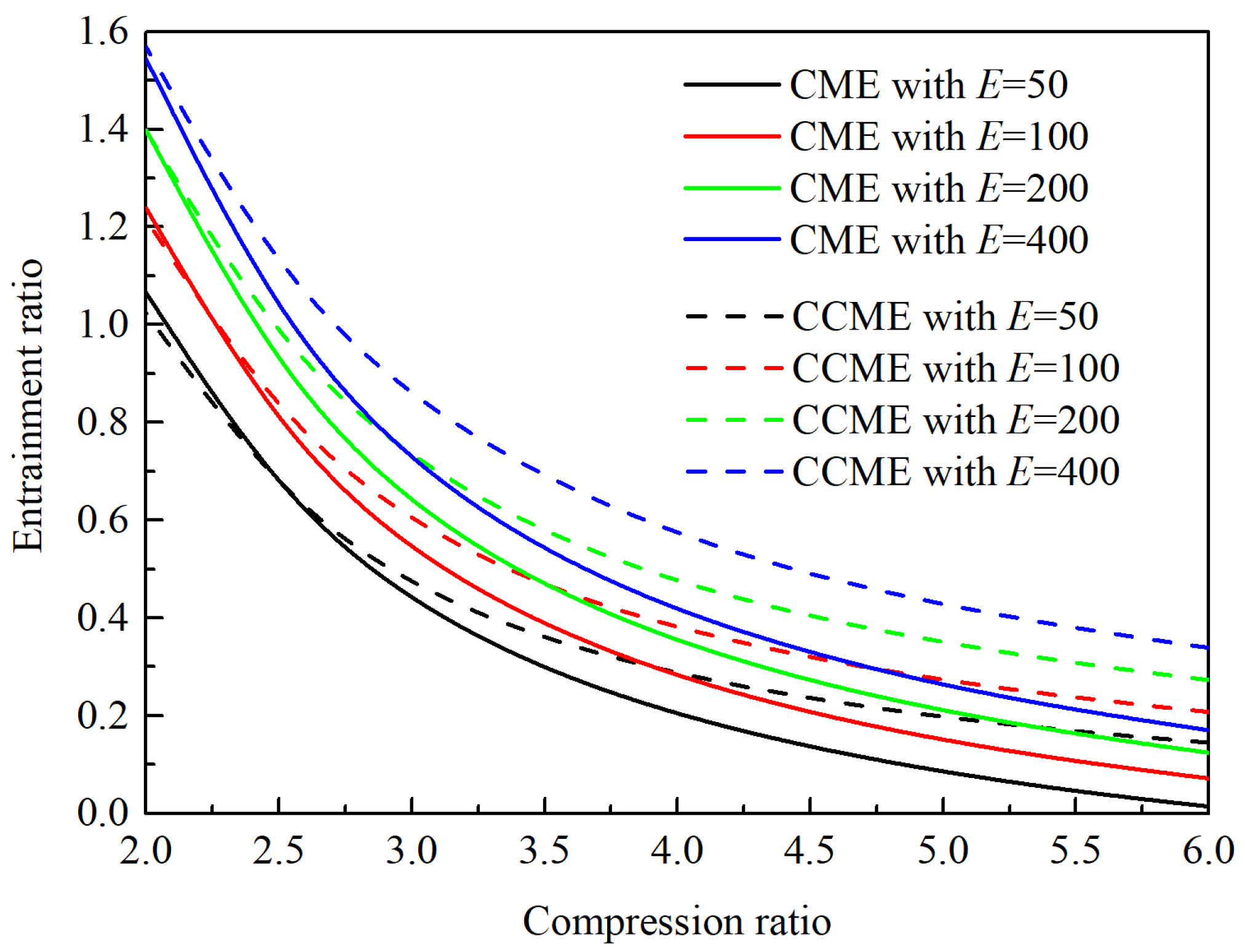
- In the design state, the entrainment ratios of the CME and CCME vary with the compression ratio. The CME exhibits a higher entrainment ratio when the compression ratio is below a certain value, while the CCME performs better when the compression ratio is above this value.
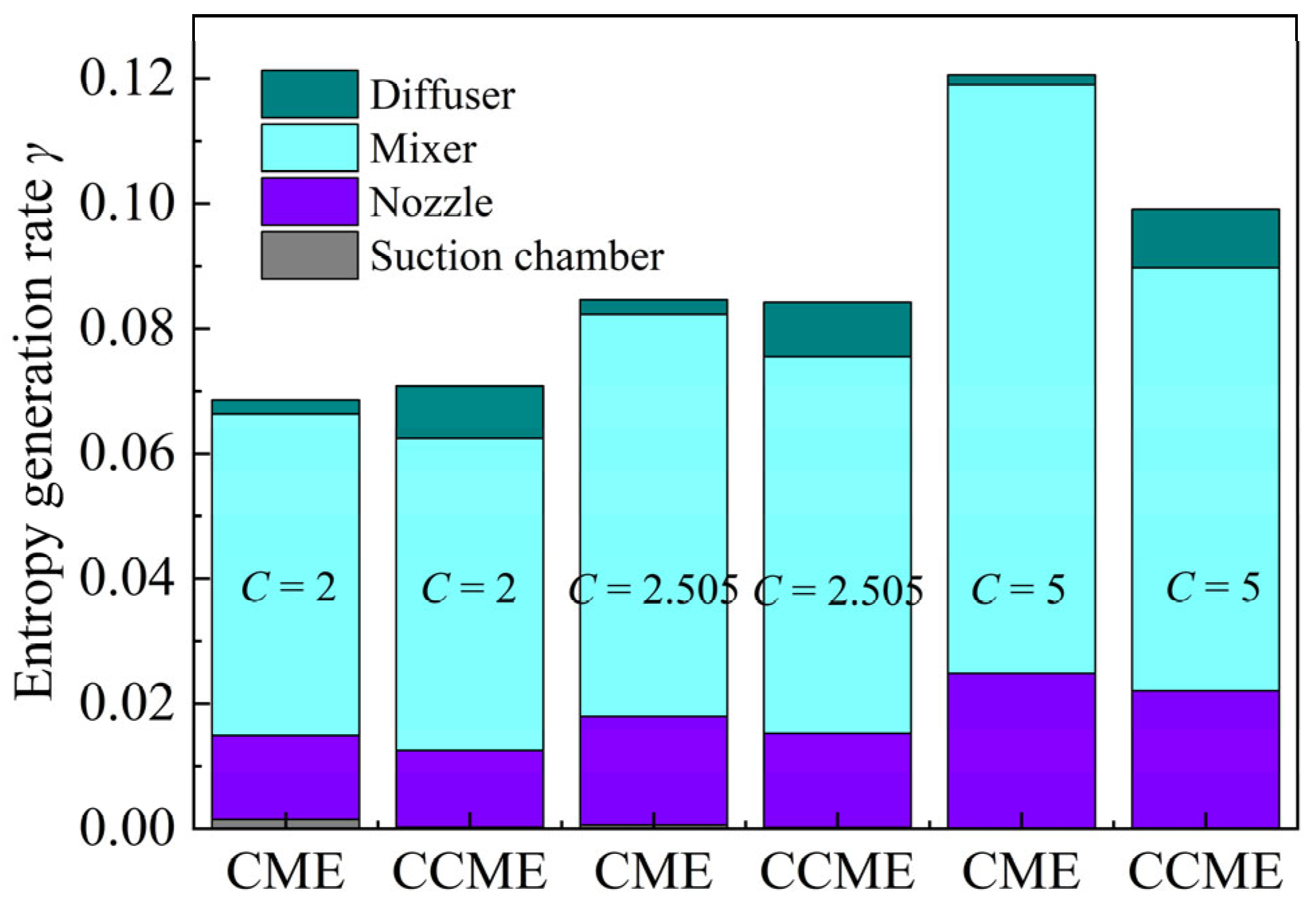
- After replacing the cylindrical mixer with a conical–cylindrical one, the mixer produces a higher entropy generation rate facing the same pressure lift, while the pressure previously located in the CME’s mixer before replacement transfers to the diffuser, reducing the entropy generation rate from the other side. This leads to an indeterminate efficiency relationship between the pressurization processes of the CME and CCME.
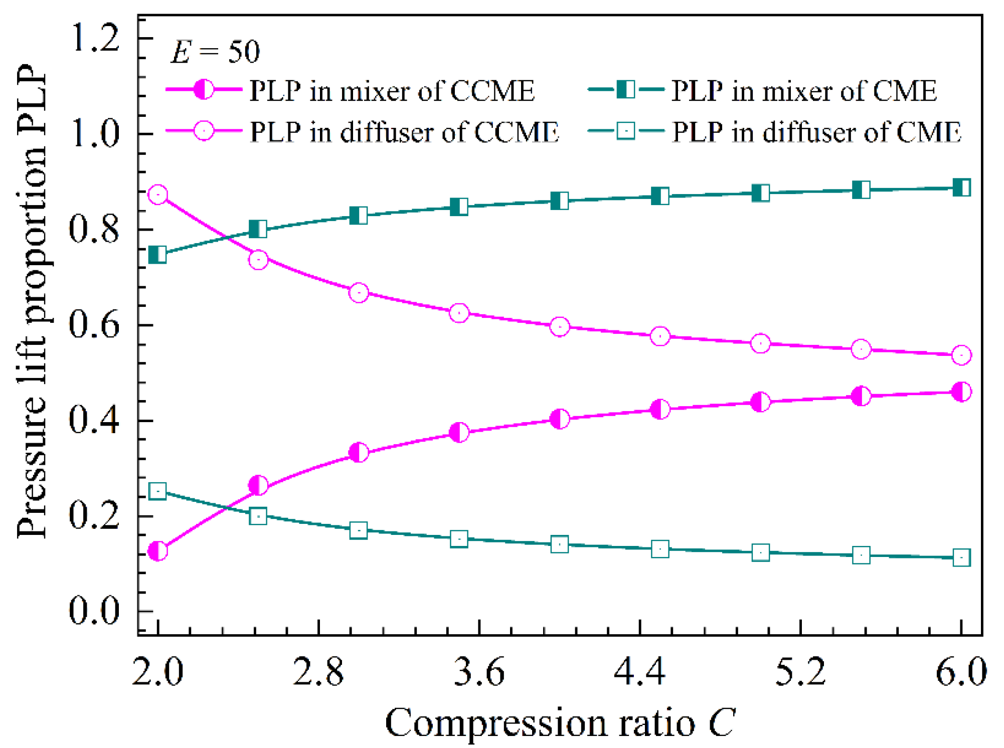
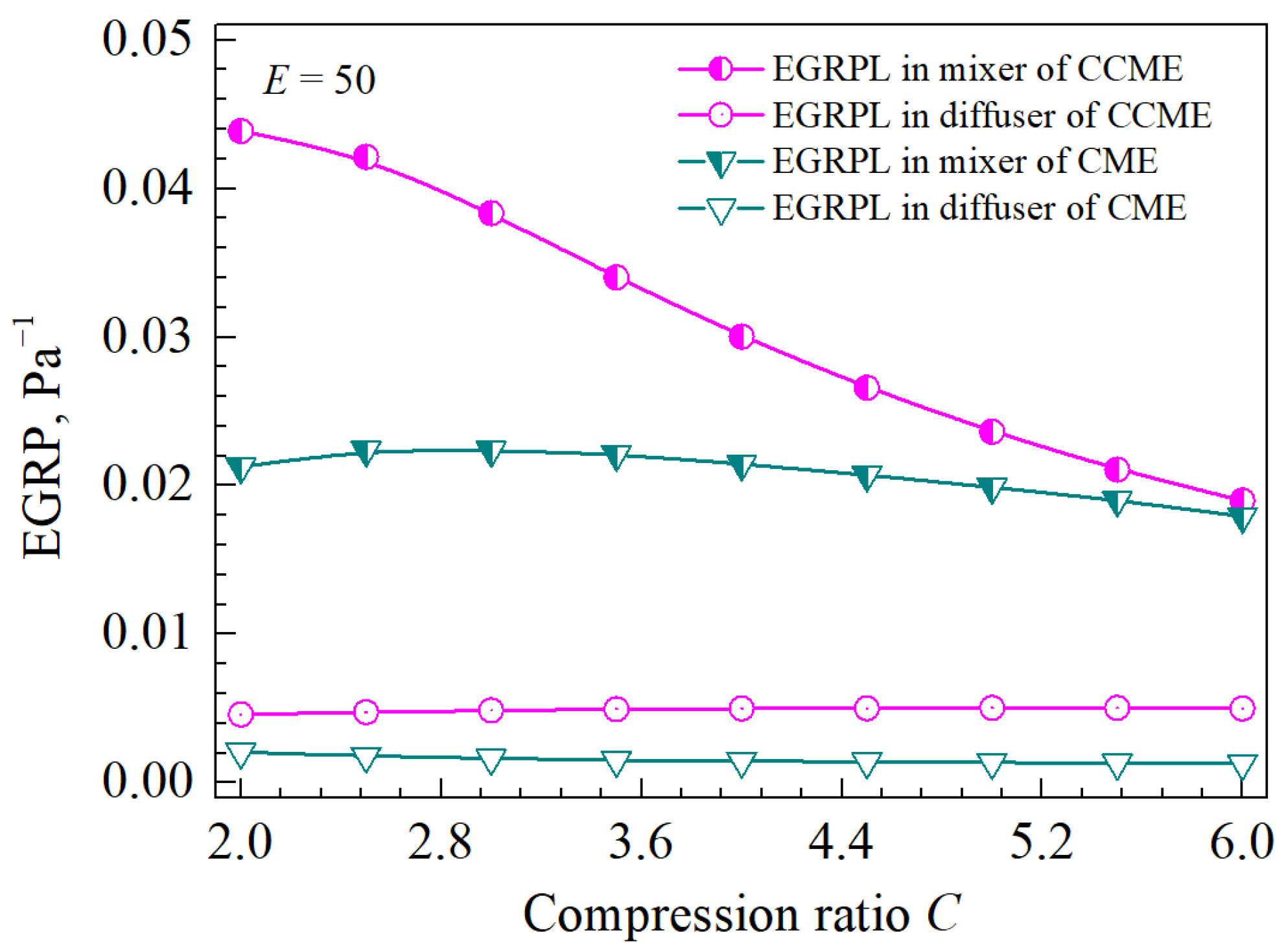
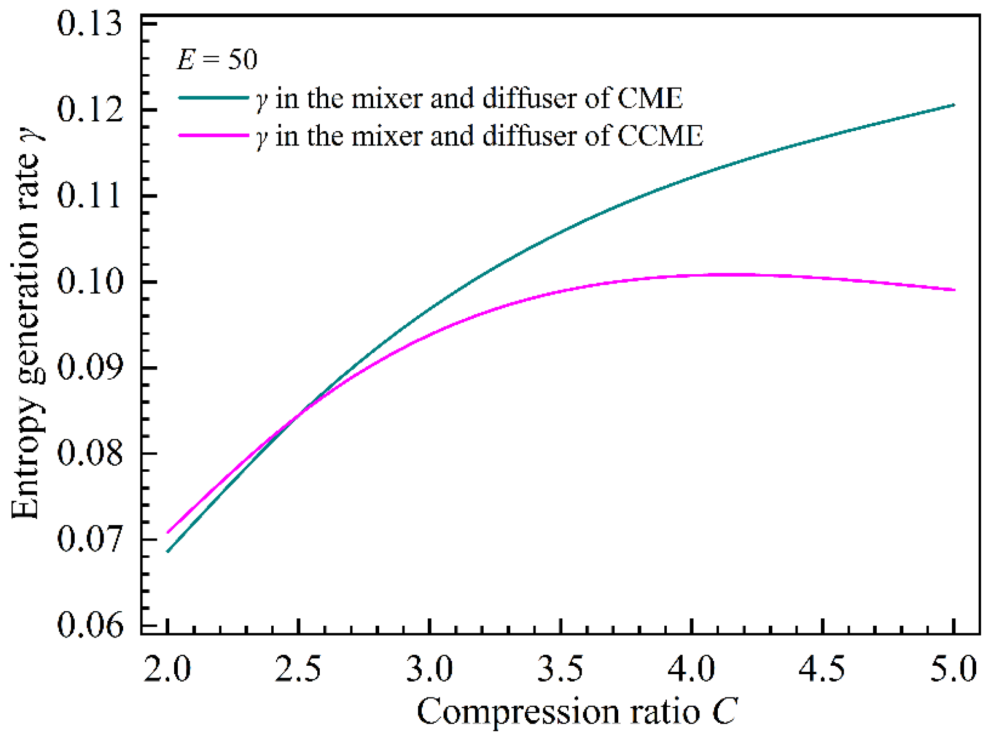
- As the compression ratio increases, PLPs in the mixers of both the CME and CCME increase slowly, but the EGRPs in the mixer of the CCME decrease more rapidly than those in the CME. The distribution characteristics of PLP and EGRP in the mixer and diffuser result in a smaller total entropy generation rate in the CME compared with the CCME under small compression ratios. Conversely, under large compression ratios, the total entropy generation rate in the CME is larger than that in the CCME.
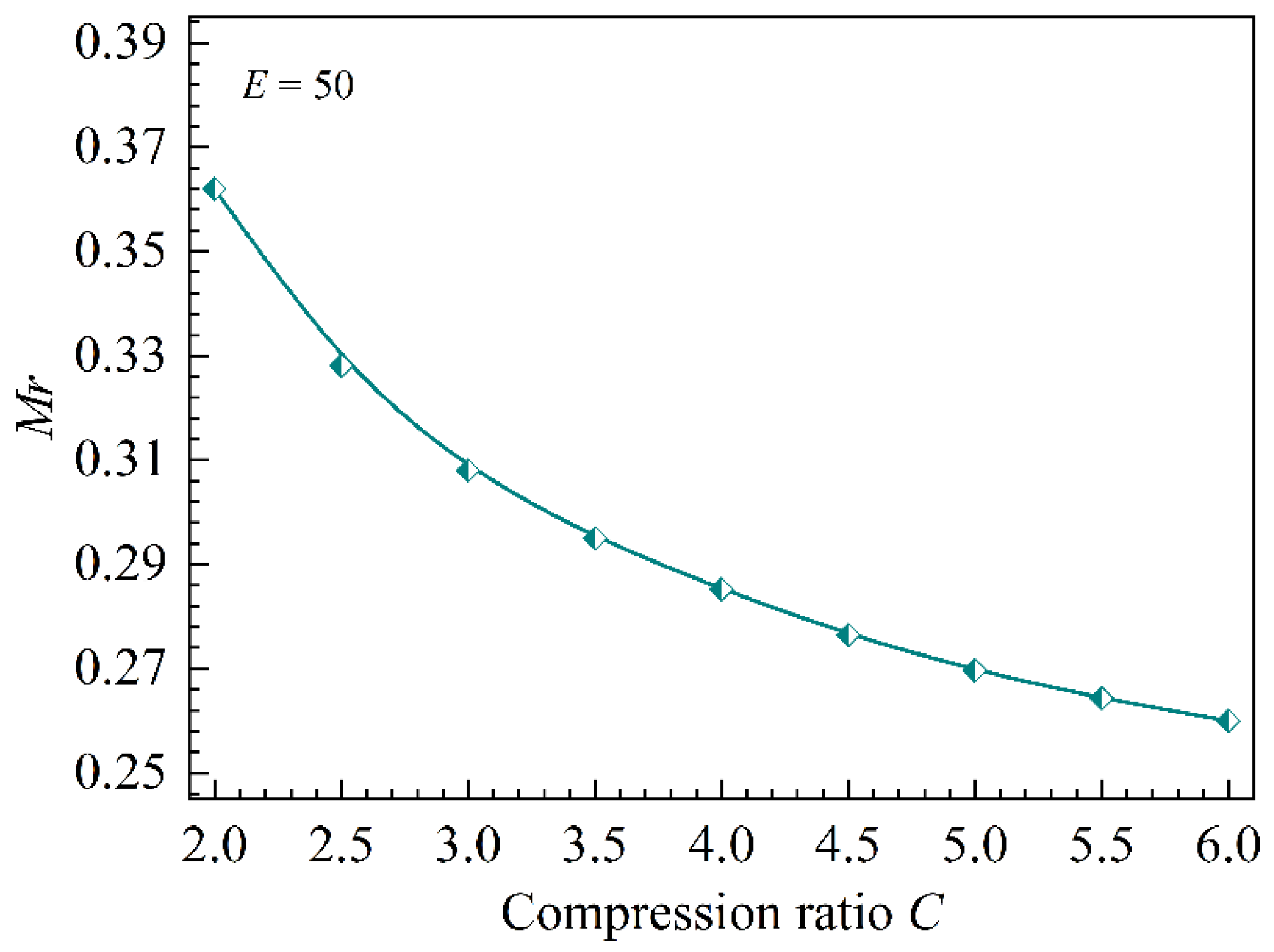
- The higher EGRP in the CCME compared with the CME is attributed to the reverse impulse exerted by the contracting wall of the CCME on the incoming mixing flow.
Author Contributions
Funding
Institutional Review Board Statement
Data Availability Statement
Conflicts of Interest
Nomenclature
| A | Area, m2 |
| Ar | Area ratio |
| C | Compression ratio |
| D | Diameter, m |
| E | Expansion ratio |
| Er | Entrainment ratio |
| h | Specific enthalphy, kJ/kg |
| k | Adiabatic index |
| L | Length |
| Mass flow rate, kg/s | |
| Mr | Ratio of the impulse from the mixer wall to the total momentum out of the mixer |
| P | Pressure, Pa |
| q | Flow-rate function of gas dynamic |
| s | Specific entropy, kJ/(kg·K) |
| t | Temperature, K |
| v | Specific volume, m3/kg |
| w | Velocity, m/s |
| Greek letters | |
| α | Ratio of the pressure lift in the conical part to the total pressure lift in the conical–cylindrical mixer |
| β | Area ratio of the mixer entrance to the mixer float |
| γ | Entropy generation rate |
| η | Isentropic efficiency |
| θ | Mixer converging angle |
| λ | Speed function of gas dynamic |
| μ | Area ratio of the secondary vapor choking section to the mixer float |
| Π | Pressure function of gas dynamic |
| φ | Coefficient of momentum loss |
| Subscripts | |
| as | Assumed value |
| cal | Calculated value |
| cho | Value in double-chocking mode |
| cri | Value in critical state |
| d | Discharge vapor |
| dif | Parameter in diffuser |
| exp | Experimental value |
| id | Ideal value |
| jet | Value of the jet flow |
| k | Parameter on cross section k |
| mix | Parameter in mixing chamber |
| noz | Parameter in nozzle |
| p | Primary vapor |
| s | Secondary vapor |
| suc | Parameter in suction chamber |
| 0 | Parameter in cross section 0 |
| 1 | Parameter in cross section 1 |
| 3 | Parameter in cross section 3 |
| Abbreviations | |
| CM | Cylindrical mixer |
| CCM | Conical–cylindrical mixer |
| CCME | Conical–cylindrical mixer ejector |
| CME | Cylindrical mixer ejector |
| EGRP | Entropy generation rate of per-unit pressure lift |
| NL | Nozzle |
| PLP | Pressure lift proportion |
| FS | Full-scale |
References
- National Bureau of Statistics. Energy Statistics Reports for China. 2021. Available online: https://data.stats.gov.cn/easyquery.htm?cn=C01 (accessed on 10 June 2022).
- Jing, W.; Yu, J.; Luo, W.; Li, C.; Liu, X. Energy-saving diagnosis model of central air-conditioning refrigeration system in large shopping mall. Energy Rep. 2021, 7, 4035–4046. [Google Scholar] [CrossRef]
- Liu, B.; Guo, X.; Xi, X.; Sun, J.; Zhang, B.; Yang, Z. Thermodynamic analyses of ejector refrigeration cycle with zeotropic mixture. Energy 2023, 263, 125989. [Google Scholar] [CrossRef]
- Cao, X.; Liang, X.; Shao, L.; Zhang, C. Performance analysis of an ejector-assisted two-stage evaporation single-stage vapor-compression cycle. Appl. Therm. Eng. 2022, 205, 118005. [Google Scholar] [CrossRef]
- Ge, J.; Chen, H.; Li, J.; Jin, Y. Experimental comparison of critical performance for variable geometry ejectors with different mixer structures. Chem. Eng. J. 2023, 478, 147487. [Google Scholar] [CrossRef]
- Eames, I.W. A new prescription for the design of supersonic jet-pumps: The constant rate of momentum change method. Appl. Therm. Eng. 2002, 22, 121–131. [Google Scholar] [CrossRef]
- Kitrattana, B.; Aphornratana, S.; Thongtip, T. Investigation on improvement potential of steam ejector performance in refrigeration cycle via constant rate of momentum change design method. Appl. Therm. Eng. 2023, 231, 120953. [Google Scholar] [CrossRef]
- Ge, J.; Chen, H.; Jin, Y.; Li, J. Conical-cylindrical mixer ejector design model for predicting optimal nozzle exit position. Energy 2023, 283, 129190. [Google Scholar] [CrossRef]
- Shestopalov, K.O.; Huang, B.J.; Petrenko, V.O.; Volovyk, O.S. Investigation of an experimental ejector refrigeration machine operating with refrigerant R245fa at design and off-design working conditions. Part 1. Theoretical analysis. Int. J. Refrig. 2015, 55, 201–211. [Google Scholar] [CrossRef]
- Kennan, J.H.; Neumann, E.P.; Mass, C. A simple air ejector. ASME J. Appl. Mech. 1942, 64, 75–82. [Google Scholar] [CrossRef]
- Fabri, J.; Siestrunck, R. Supersonic air ejectors. Adv. Appl. Mech. 1958, 5, 1–34. [Google Scholar]
- Paliwoda, A. Design problems of supersonic ejectors operating as booster compressors in refrigerating systems. In Progress in Refrigeration Science and Technology; Pergamon Press Ltd.: Oxford, UK, 1965; pp. 589–598. [Google Scholar]
- Sokolov, E.Y.; Zinger, N. Jet Devices; Energoatomizdat: Moscow, Russia, 1989. [Google Scholar]
- Huang, B.; Chang, J.; Wang, C. A 1-D analysis of ejector performance. Int. J. Refrig. 1999, 22, 354–364. [Google Scholar] [CrossRef]
- Zhu, Y.; Cai, W.; Wen, C.; Li, Y. Shock circle model for ejector performance evaluation. Energy Convers. Manag. 2007, 48, 2533–2541. [Google Scholar] [CrossRef]
- Cizungu, K.; Mani, A.; Groll, M. Performance comparison of vapor jet refrigeration system with environment friendly working fluids. Appl. Therm. Eng. 2001, 21, 585–598. [Google Scholar] [CrossRef]
- Valle, J.G.; Jabardo, J.M.S.; Ruiz, F.C.; Alonso, J.S.J. A one dimensional model for the determination of an ejector entrainment ratio. Int. J. Refrig. 2012, 35, 772–784. [Google Scholar] [CrossRef]
- Chen, W.; Liu, M.; Chong, D.; Yan, J.; Little, A.B.; Bartosiewicz, Y. A 1D model to predict ejector performance at critical and sub-critical operational regimes. Int. J. Refrig. 2013, 36, 1750–1761. [Google Scholar] [CrossRef]
- Kumar, V.; Sachdeva, G. 1-D model for finding geometry of a single phase ejector. Energy 2018, 165, 75–92. [Google Scholar] [CrossRef]
- Tashtoush, B.; Nayfeh, Y. Energy and economic analysis of a variable-geometry ejector in solar cooling systems for residential buildings. J. Energy Storage 2020, 27, 101061. [Google Scholar] [CrossRef]
- Metsue, A.; Debroeyer, R.; Poncet, S.; Bartosiewicz, Y. An improved thermodynamic model for supersonic real-gas ejectors using the compound-choking theory. Energy 2022, 238, 121856. [Google Scholar] [CrossRef]
- Guo, H.; Wang, L.; Wang, X. A full operating conditions ejector model for refrigeration systems driven by low-grade heat sources. Case Stud. Therm. Eng. 2024, 60, 104670. [Google Scholar] [CrossRef]
- Keenan, J.H.; Neumann, E.P. An investigation of ejector design by analysis and experiment. J. Appl. Mech. 1950, 72, 299–309. [Google Scholar] [CrossRef]
- Munday, J.T.; Bagster, D.F. A New Ejector Theory Applied to Steam Jet Refrigeration. Ind. Eng. Chem. Process Des. Dev. 1977, 16, 442–449. [Google Scholar] [CrossRef]
- Aly, N.H.; Karameldin, A.; Shamloul, M.M. Modelling and simulation of steam jet ejectors. Desalination 1999, 123, 1–8. [Google Scholar] [CrossRef]
- El-dessouky, H.; Ettouney, H.; Alatiqi, I.; Al-Nuwaibit, G. Evaluation of steam jet ejectors. Chem. Eng. Process. 2002, 41, 551–561. [Google Scholar] [CrossRef]
- Liu, J.; Wang, L.; Jia, L. A predictive model for the performance of the ejector in refrigeration system. Energy Convers. Manag. 2017, 150, 269–276. [Google Scholar] [CrossRef]
- Wang, K.; Wang, L.; Gao, R. An extended mechanism model of gaseous ejectors. Energy 2023, 264, 126094. [Google Scholar] [CrossRef]
- Shestopalov, K.O.; Huang, B.J.; Petrenko, V.O.; Volovyk, O.S. Investigation of an experimental ejector refrigeration machine operating with refrigerant R245fa at design and off-design working condition. Part 2. Theoretical and experimental results. Int. J. Refrig. 2015, 55, 212–223. [Google Scholar] [CrossRef]
- del Valle, J.G.; Saíz Jabardo, J.M.; Castro Ruiz, F.; San José Alonso, J.F. An experimental investigation of a R-134a ejector refrigeration system. Int. J. Refrig. 2014, 46, 105–113. [Google Scholar] [CrossRef]
- Zhu, Y.; Cai, W.; Wen, C.; Li, Y. Numerical investigation of geometry parameters for design of high performance ejectors. Appl. Therm. Eng. 2009, 29, 898–905. [Google Scholar] [CrossRef]
- Chen, H.; Lu, W.; Cao, C.; Yang, L. Applicability analysis on ejectors with cylindrical and conical mixing chambers. Huagong Xuebao/CIESC J. 2013, 64, 2043–2049. [Google Scholar]
- Galanis, N.; Sorin, M. Ejector design and performance prediction. Int. J. Therm. Sci. 2016, 104, 315–329. [Google Scholar] [CrossRef]
- Mcgovern, R.K.; Narayan, G.P.; John, H.L.V. Analysis of reversible ejectors and definition of an ejector efficiency. Int. J. Therm. Sci. 2012, 54, 153–166. [Google Scholar] [CrossRef]
- Luo, J.; Chen, G.; Wang, Q.; Zhang, S. Analysis on the optimal mixing pressure and efficiency limit of an ideal ejector. Energy Rep. 2021, 7, 4335–4347. [Google Scholar] [CrossRef]
- Omidvar, A.; Ghazikhani, M.; Razavi, S.M.R.M. Entropy analysis of a solar-driven variable geometry ejector using computational fluid dynamics. Energy Convers. Manag. 2016, 119, 435–443. [Google Scholar] [CrossRef]
- Li, H.; Wang, X.; Huang, H.; Ning, J.; Li, A.; Tu, J. Numerical study on the effect of superheat on the steam ejector internal flow and entropy generation for MED-TVC desalination system. Desalination 2022, 537, 115874. [Google Scholar] [CrossRef]
- Liu, J.; Wang, L.; Jia, L.; Wang, X. Thermodynamic modeling and sensitivity analysis of ejector in refrigeration system. Int. J. Heat Mass Tran. 2018, 126, 485–492. [Google Scholar] [CrossRef]
- Chen, H.J.; Zhu, J.H.; Ge, J.; Lu, W.; Zheng, L.X. A cylindrical mixing chamber ejector analysis model to predict the optimal nozzle exit position. Energy 2020, 208, 118302. [Google Scholar] [CrossRef]
- Sinopec Beijing Design Institute. Specification for Design of Steam-Jet Vacuum Pump for Petrochemical; State Bureau of Petroleum and Chemical Industry: Beijing, China, 2000. [Google Scholar]
- Chunnanond, K.; Aphornratana, S. Ejectors: Applications in refrigeration technology. Renew. Sustain. Energy Rev. 2004, 8, 129–155. [Google Scholar] [CrossRef]
- You, Y.; Deng, J.J.; Zhang, J.; Shen, Y. University Physics Experiments; Beijing Institute of Technology Press: Beijing, China, 2019. [Google Scholar]
- ISO 2768–1:1989; General Tolerance. Part 1: Tolerances for Linear and Angular Dimensions without Individual Tolerance Indications. Alteams: Laihia, Finland, 1989.
- Nabavi, S.R.; Wang, Z.; Rangaiah, G.P. Sensitivity Analysis of Multi-Criteria Decision-Making Methods for Engineering Applications. Ind. Eng. Chem. Res. 2023, 62, 6707–6722. [Google Scholar] [CrossRef]
- Chen, H.; Zhu, J.; Lu, W. Optimized selection of one- and two-stage ejectors under design and off-design conditions. Energy Convers. Manag. 2018, 173, 743–752. [Google Scholar] [CrossRef]
- Lemmon, E.W.; Huber, M.L.; McLinden, M.O.; Bell, I. Reference Fluid Thermodynamic and Transport Properties Database (REFPROP); National Institute of Standards and Technology, Standard Reference Data Program: Gaithersburg, MD, USA, 2013. [Google Scholar]
- Liu, J.; Wang, L.; Jia, L.; Xue, H. Thermodynamic analysis of the steam ejector for desalination applications. Appl. Therm. Eng. 2019, 159, 113883. [Google Scholar] [CrossRef]
- Khennich, M.; Sorin, M.; Galanis, N. Exergy flows inside a one phase ejector for refrigeration systems. Energies 2016, 9, 212. [Google Scholar] [CrossRef]


| Year | Scholars | Conclusions |
|---|---|---|
| 1942 | Keenan et al. [10] | The design model of ejector that satisfies the equations of mass conservation, energy conservation, and momentum conservation is proposed. |
| 1958 | Fabri et al. [11] | A formula for calculating flow resistance in circular mixing chamber is introduced. |
| 1965 | Paliwoda et al. [12] | The isentropic efficiencies for the nozzle, suction chamber, and diffuser, as well as the momentum loss coefficient for the mixer are introduced. |
| 1989 | Sokolov et al. [13] | The optimal working state of the ejector, which occurs at the intersection of the conditions characterized by a double-choking mode and a single-choking mode, is pointed out. |
| 1999 | Huang et al. [14] | The correction coefficient for the working flow rate is considered. |
| 2007 | Zhu et al. [15] | An exponential two-dimensional velocity distribution model to calculate the entrainment ratio of double-choking mode is introduced. |
| 2012 | Cizungu et al. [16] | Calculation models for single-phase and two-phase working fluid nozzles are introduced. |
| 2012 | Valle et al. [17] | The Prandtl–Meyer expansion wave is considered to calculate the entrainment ratio and nozzle exit position. |
| 2017 | Chen et al. [18] | The theory of expansion wave is used to determine the velocity distribution of the choking section of the secondary vapor. |
| 2018 | Kumar et al. [19] | The Fano flow relationship to calculate the axial dimensions of ejectors is introduced. |
| 2020 | Tashtoush et al. [20] | The relationship between the momentum loss coefficient in the mixer and the compression ratio, as well as the cross-sectional ratio of the ejector is considered. |
| 2022 | Metsue et al. [21] | An ejector model that is based on the properties of real gases and compound-choking theory, which can be applied under both design and off-design operating conditions, is proposed. |
| 2024 | Guo et al. [22] | The linear relationship that exists between the mixing loss coefficient and back pressure in the context of single-choking mode is considered. |
| Year | Scholars | Conclusions |
|---|---|---|
| 1950 | Keenan et al. [23] | Propose a conical–cylindrical mixer ejector model that is based on momentum, energy, and mass conservation equations. |
| 1977 | Munday et al. [24] | Point out that pressurization in the conical–cylindrical mixer is carried out through a shock wave. |
| 1999 | Aly et al. [25] | Propose a conical–cylindrical mixer ejector model that combines thermodynamic and aerodynamic methods. |
| 2002 | El-Dessouky et al. [26] | Propose using the critical back pressure ratio as the basis for determining whether shock waves occur in the mixer. |
| 2015 | Shestopalov et al. [9] | Propose a hypothesis that the secondary vapor choking section coincides with the nozzle outlet section. |
| 2017 | Liu et al. [27] | Elaborate on the pressure rise ratio and boosting rate of vapor in the cylindrical sections of the mixer and diffuser. |
| 2023 | Wang et al. [28] | Introduce an equivalent equation for the momentum equation of the mixer to reduce the requirement for empirical coefficients in the model. |
| Scholars | Conclusions |
|---|---|
| Keenan et al. [23] | The CCME may perform better than the CME when the ejector area ratio (Ar) is smaller than 10. |
| Sokolov et al. [13] | The CCME may perform better than the CME when the compression ratio is larger than 2.5. |
| Shestopalov et al. [29] | Given a generating temperature of Tp = 88~102 °C and an evaporating temperature of Ts = 81.6 °C, the CCME with a mixer diameter of 13.02 mm and a nozzle throat diameter of 4.21 mm has a larger entrainment ratio and lower critical back pressure compared with the CME. |
| Valle et al. [30] | When the mixer diameter is 4.8 mm and the nozzle throat diameter is 4 mm, with Tp = 84.39 °C and Ts = 10 °C, the CCME exhibits a larger entrainment ratio and lower critical back pressure compared with the CME. |
| Shestopalov et al. [9] | Considering the same primary and secondary vapor parameters (Tp = 95 °C and Ts = 12 °C), as well as the same condensing temperature of 32 °C, the CCME outperforms the CME when using various organic refrigerants. |
| Zhu et al. [31] | For an ejector with a primary pressure of Pp = 5 bar, a secondary pressure of Ps = 0.43 bar, and a condensing pressure of Pd = 0.8 bar, the CCME demonstrates a conspicuous performance improvement over the CME. |
| Parameters | Sensor in Generator | Sensor in Evaporator | Sensor in Condenser |
|---|---|---|---|
| Measuring range | 0~350 kPa | 0~100 kPa | 0~100 kPa |
| Accuracy | 0.075% FS | 0.075% FS | 0.075% FS |
| Parameter | Entrainment Ratio | Compression Ratio |
|---|---|---|
| Range of uncertainty, % | 0.11–0.64 | 0.72–2.0 |
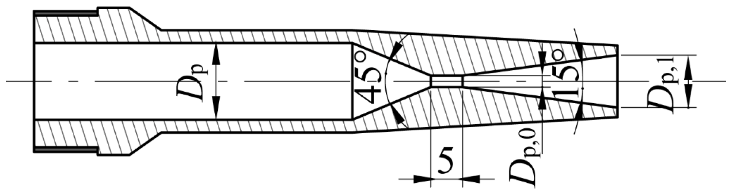
| Nozzle | Dp, mm | Dp,0, mm | Dp,1, mm |
|---|---|---|---|
| NL.1 | 13.0 | 2.0 | 3.9 |
| NL.2 | 13.0 | 2.0 | 6.2 |
| NL.3 | 13.0 | 2.0 | 7.2 |
| NL.4 | 13.0 | 2.0 | 8.2 |
| NL.5 | 13.0 | 1.8 | 8.5 |
| NL.6 | 13.0 | 1.8 | 9.6 |
| Mixing–Diffusing Chamber | Dsuc, mm | Dd,3, mm | Dd, mm |
|---|---|---|---|
| CM.1 | 32.0 | 7.4 | 15.8 |
| CM.2 | 32.0 | 10.2 | 21.9 |
| CM.3 | 32.0 | 12.2 | 25.6 |
| CM.4 | 32.0 | 14.5 | 30.7 |
| CM.5 | 32.0 | 14.5 | 32.0 |
| CM.6 | 32.0 | 15.5 | 33.4 |
| Mixing–Diffusing Chamber | Dsuc, mm | D1, mm | Dd,3, mm |
|---|---|---|---|
| CCM.1 | 32.0 | 12.1 | 7.4 |
| CCM.2 | 32.0 | 16.8 | 10.2 |
| CCM.3 | 32.0 | 19.7 | 12.2 |
| CCM.4 | 32.0 | 23.6 | 14.5 |
| CCM.5 | 32.0 | 24.2 | 14.5 |
| CCM.6 | 32.0 | 25.8 | 15.5 |
| Mixing–Diffusing Chamber | Nozzle | Pp, kPa | Ps, kPa | Pd,exp, kPa | Pd,cal, kPa | Errors | Erexp | Ercal | Errors |
|---|---|---|---|---|---|---|---|---|---|
| CM.1 | NL.1 | 19.0 | 1.23 | 2.62 | 2.72 | 3.82% | 0.620 | 0.614 | −0.97% |
| CM.2 | NL.2 | 70.2 | 1.23 | 4.86 | 4.85 | −0.21% | 0.270 | 0.272 | 0.74% |
| CM.3 | NL.3 | 101.4 | 1.23 | 5.19 | 5.18 | −0.19% | 0.275 | 0.256 | −6.91% |
| CM.4 | NL.4 | 143.4 | 1.23 | 5.37 | 5.39 | 0.37% | 0.289 | 0.278 | −3.81% |
| CM.5 | NL.5 | 198.7 | 1.23 | 6.17 | 5.95 | −3.57% | 0.248 | 0.233 | −6.05% |
| CM.6 | NL.6 | 270.3 | 1.23 | 7.36 | 7.11 | −3.40% | 0.197 | 0.173 | −12.2% |
| Mixing–Diffusing Chamber | Nozzle | Pp, kPa | Ps, kPa | Pd,exp, kPa | Pd,cal, kPa | Errors | Erexp | Ercal | Errors |
|---|---|---|---|---|---|---|---|---|---|
| CCM.1 | NL.1 | 19.0 | 1.23 | 2.37 | 2.43 | 2.53% | 0.756 | 0.764 | 1.06% |
| CCM.2 | NL.2 | 70.2 | 1.23 | 4.67 | 4.61 | −1.28% | 0.363 | 0.369 | 1.65% |
| CCM.3 | NL.3 | 101.4 | 1.23 | 4.96 | 4.86 | −2.02% | 0.387 | 0.392 | 1.29% |
| CCM.4 | NL.4 | 143.4 | 1.23 | 4.91 | 5.04 | 2.65% | 0.412 | 0.417 | 1.21% |
| CCM.5 | NL.5 | 198.7 | 1.23 | 5.60 | 5.50 | −1.79% | 0.396 | 0.411 | 3.79% |
| CCM.6 | NL.6 | 270.3 | 1.23 | 6.38 | 6.30 | −1.25% | 0.363 | 0.377 | 3.86% |
Disclaimer/Publisher’s Note: The statements, opinions and data contained in all publications are solely those of the individual author(s) and contributor(s) and not of MDPI and/or the editor(s). MDPI and/or the editor(s) disclaim responsibility for any injury to people or property resulting from any ideas, methods, instructions or products referred to in the content. |
© 2024 by the authors. Licensee MDPI, Basel, Switzerland. This article is an open access article distributed under the terms and conditions of the Creative Commons Attribution (CC BY) license (https://creativecommons.org/licenses/by/4.0/).
Share and Cite
Chen, H.; Ge, J.; Xu, Z. A Study on the Evolution Laws of Entrainment Performances Using Different Mixer Structures of Ejectors. Entropy 2024, 26, 891. https://doi.org/10.3390/e26110891
Chen H, Ge J, Xu Z. A Study on the Evolution Laws of Entrainment Performances Using Different Mixer Structures of Ejectors. Entropy. 2024; 26(11):891. https://doi.org/10.3390/e26110891
Chicago/Turabian StyleChen, Hongjie, Jing Ge, and Zhizhou Xu. 2024. "A Study on the Evolution Laws of Entrainment Performances Using Different Mixer Structures of Ejectors" Entropy 26, no. 11: 891. https://doi.org/10.3390/e26110891
APA StyleChen, H., Ge, J., & Xu, Z. (2024). A Study on the Evolution Laws of Entrainment Performances Using Different Mixer Structures of Ejectors. Entropy, 26(11), 891. https://doi.org/10.3390/e26110891