
A Low Sampling Rate Receiver Design for Multi-Antenna Multi-User OFDM Systems


Abstract
:1. Introduction
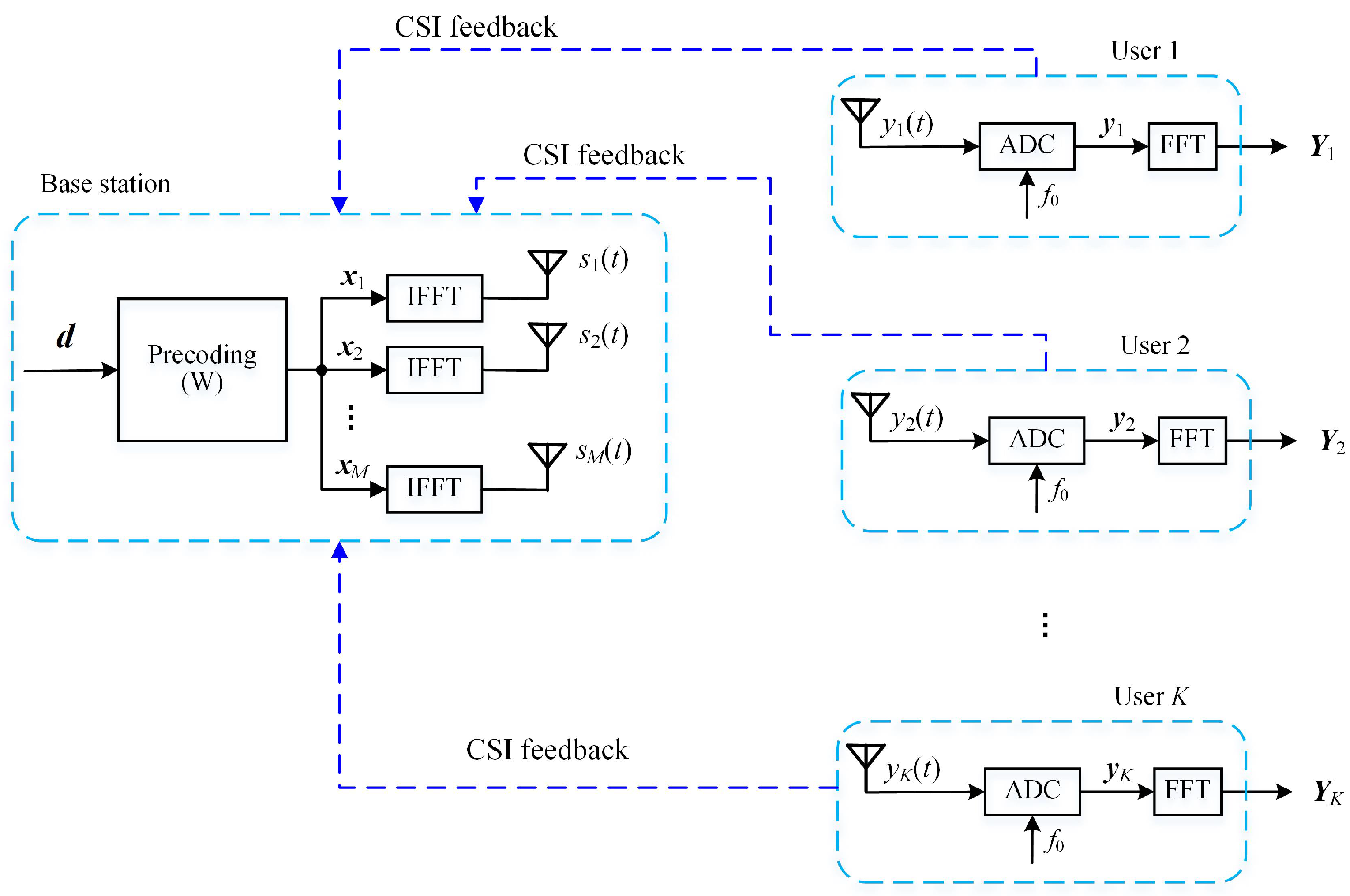
2. OFDM Systems
2.1. Signal Model
2.2. Subcarrier Allocation
2.3. Precoding
2.4. Equivalent Channel Model
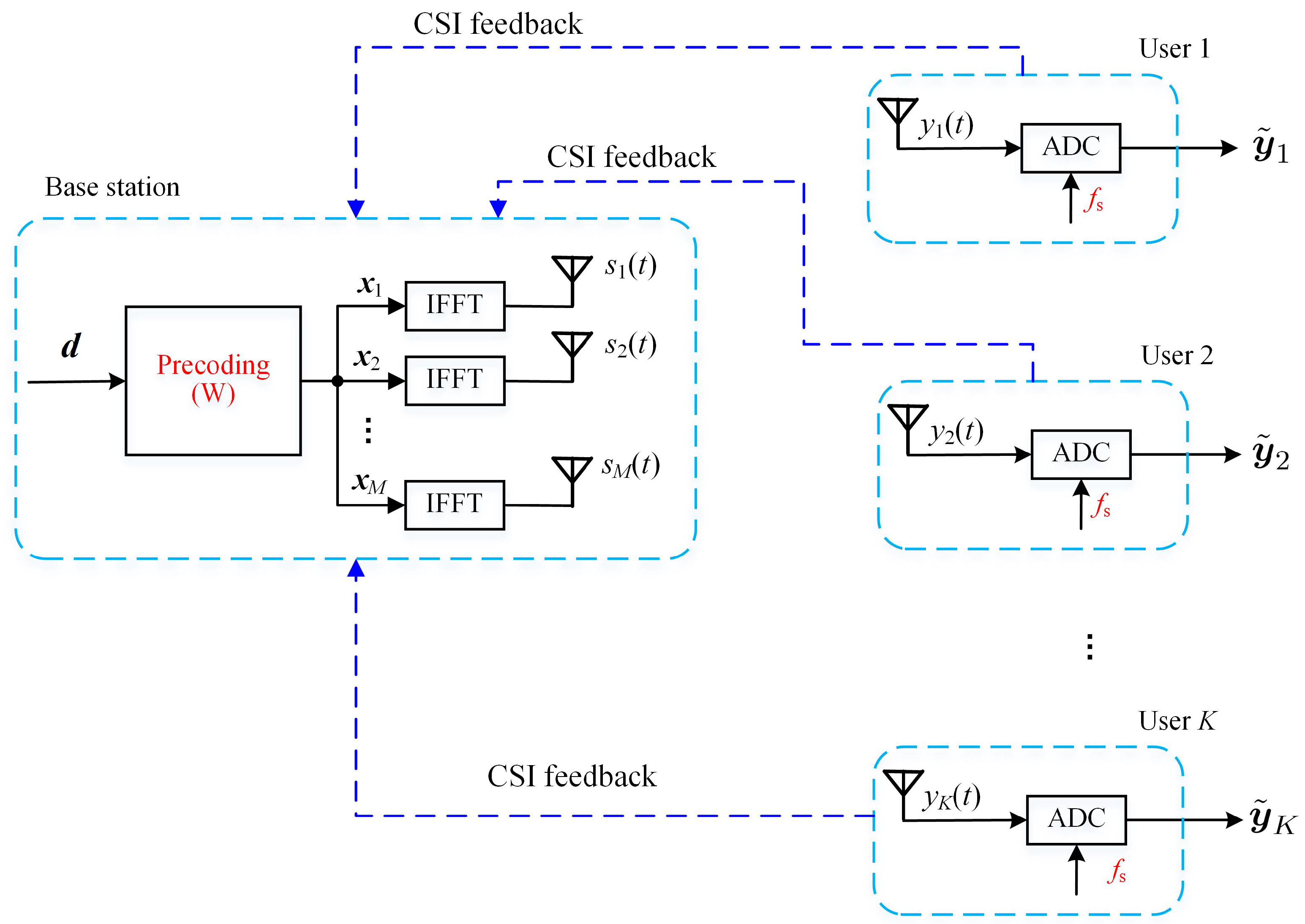
3. Proposed Low Sampling Rate Design
- In the proposed scheme, the sampling rate of the ADC of the receiver was reduced to ;
- An overall ZF precoder was used at the BS, rather than the per subcarrier MRT precoder as in (12), in order to enable the low sampling rate of the receiver;
- The FFT module was no longer required at the receiver.
3.1. Signal Model
3.2. Precoding
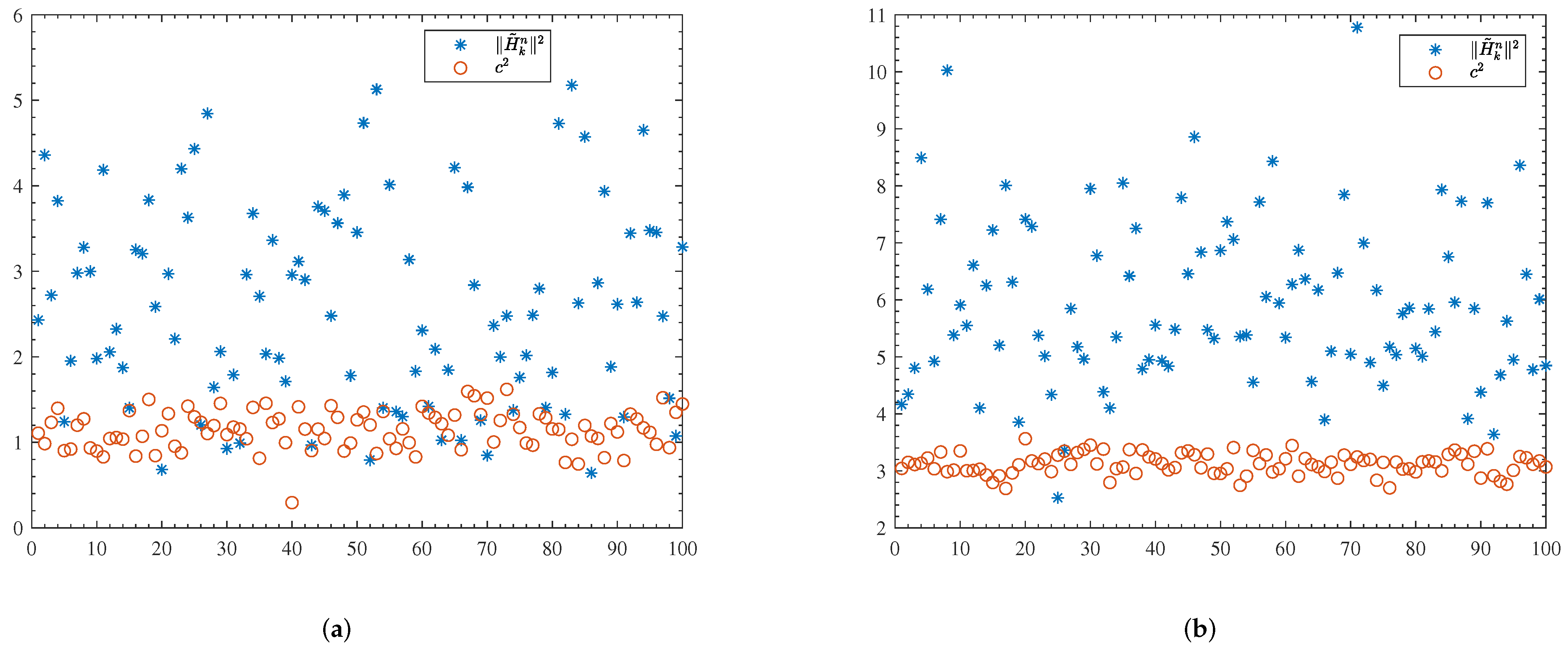
3.3. Equivalent Channel Model
4. Simulation Results
4.1. Simulation Setting
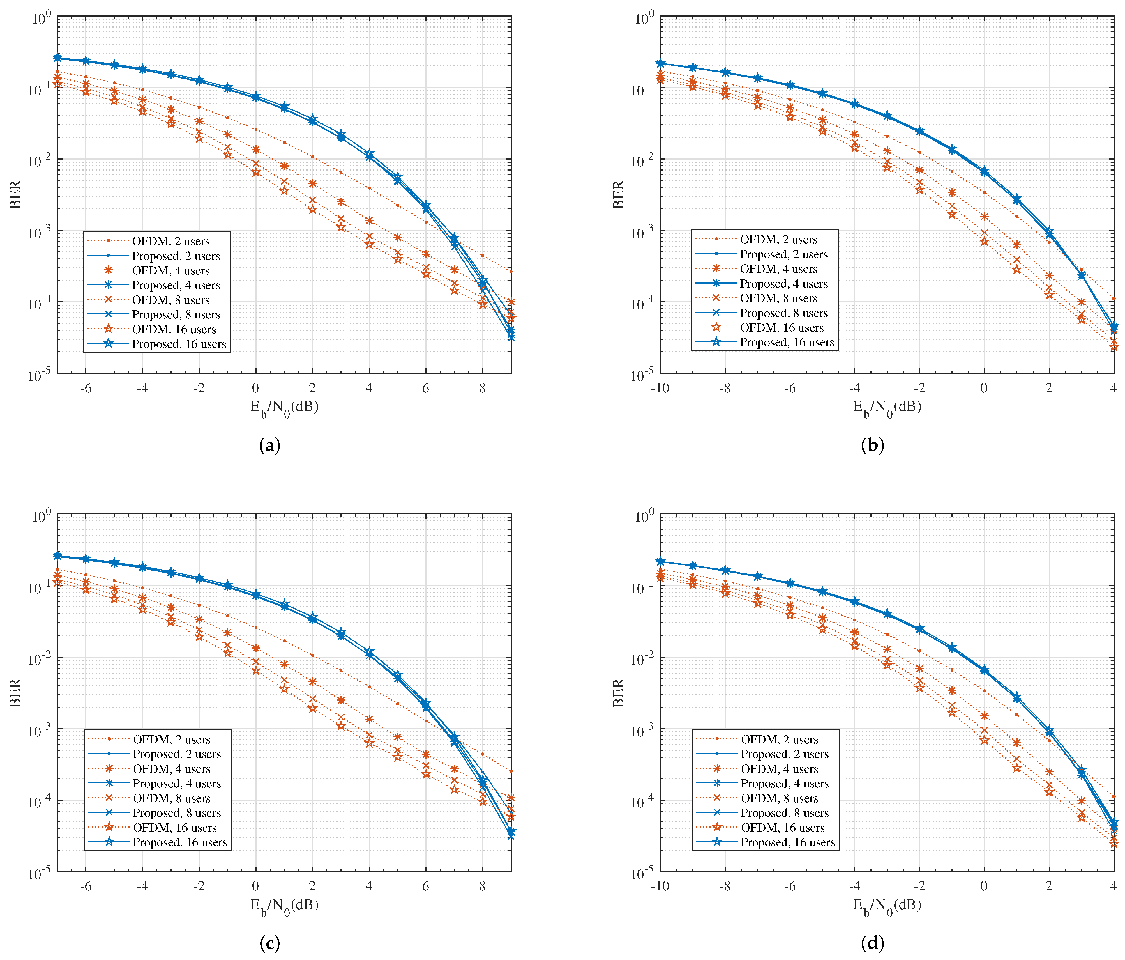
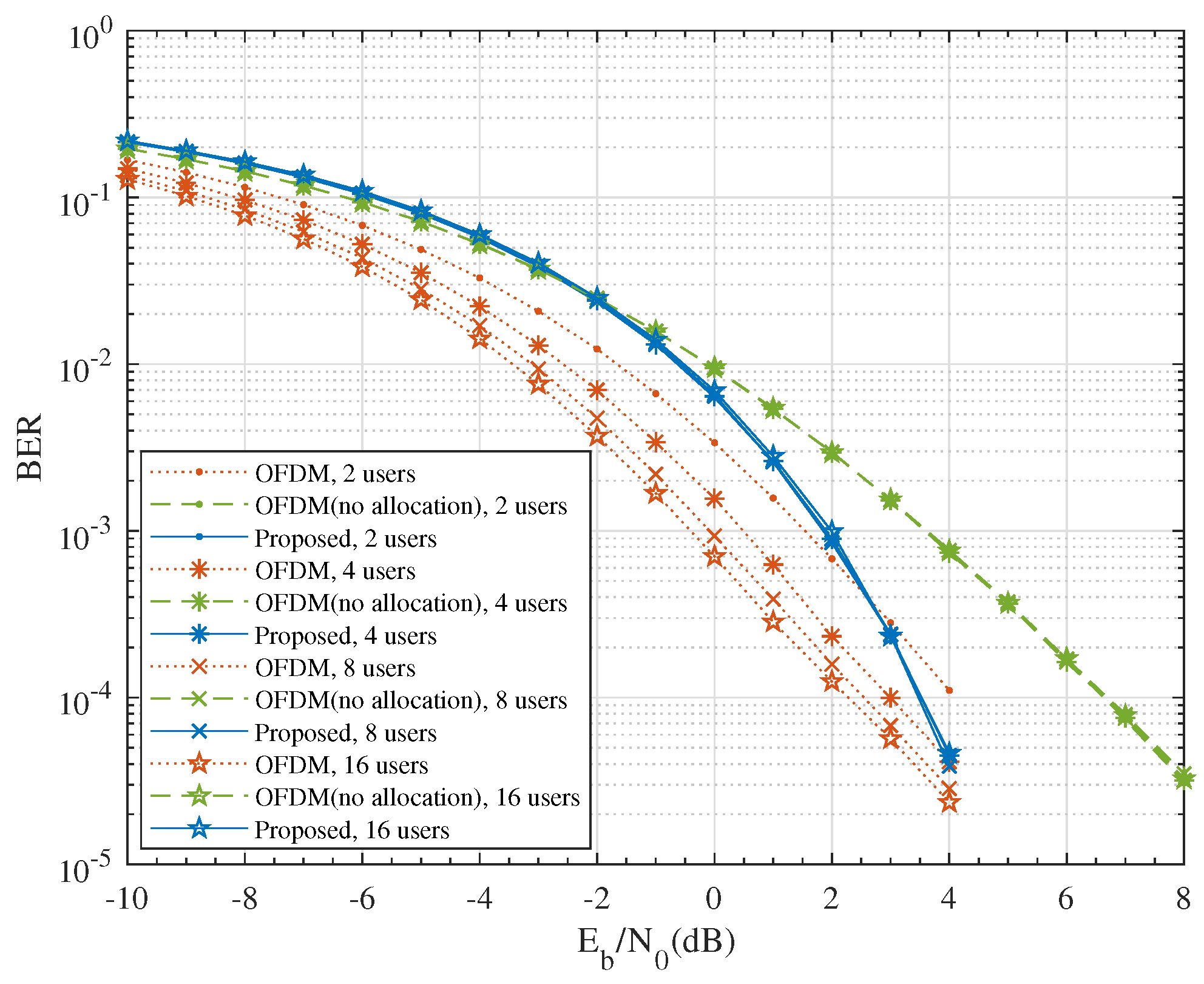
4.2. BER
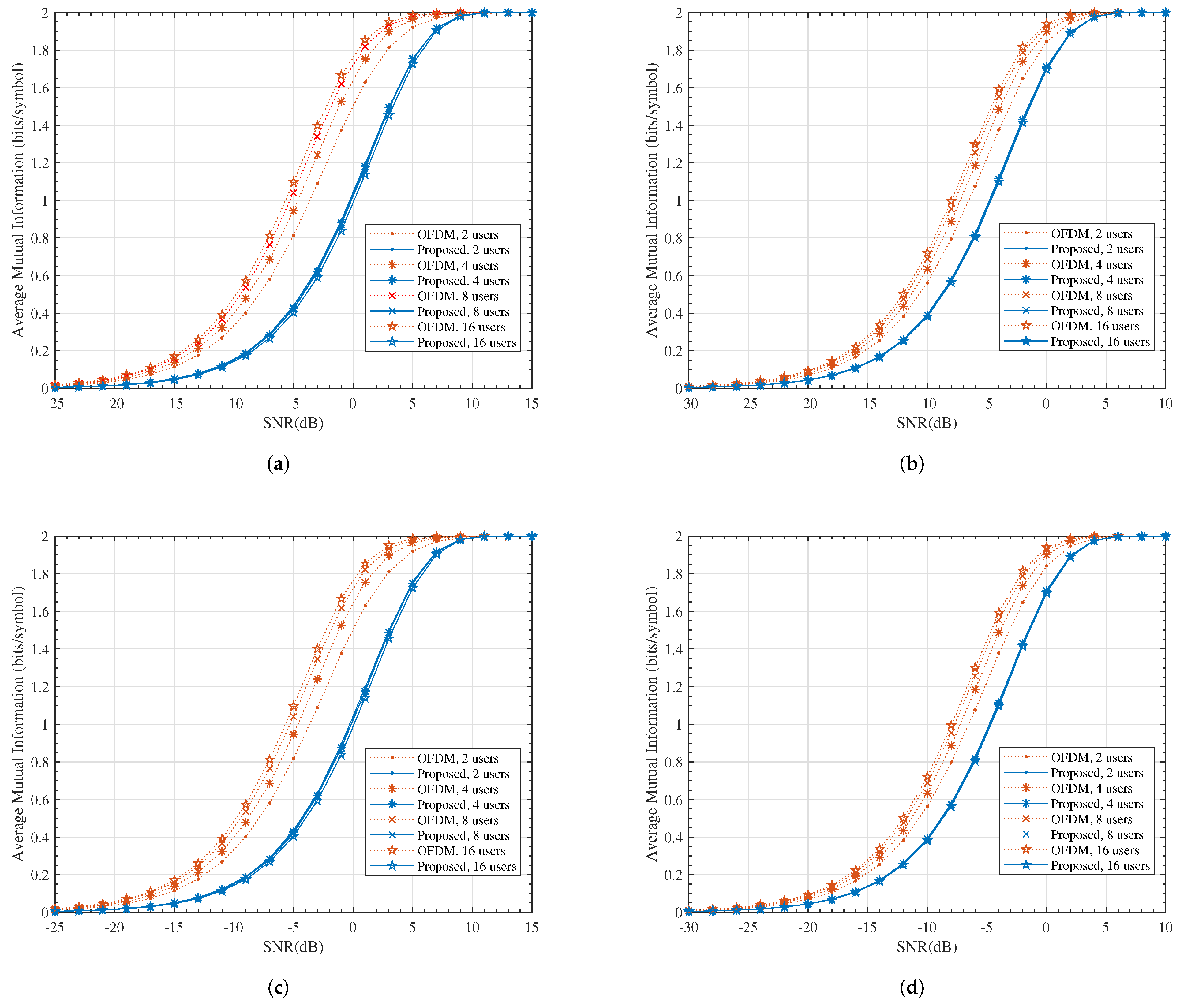
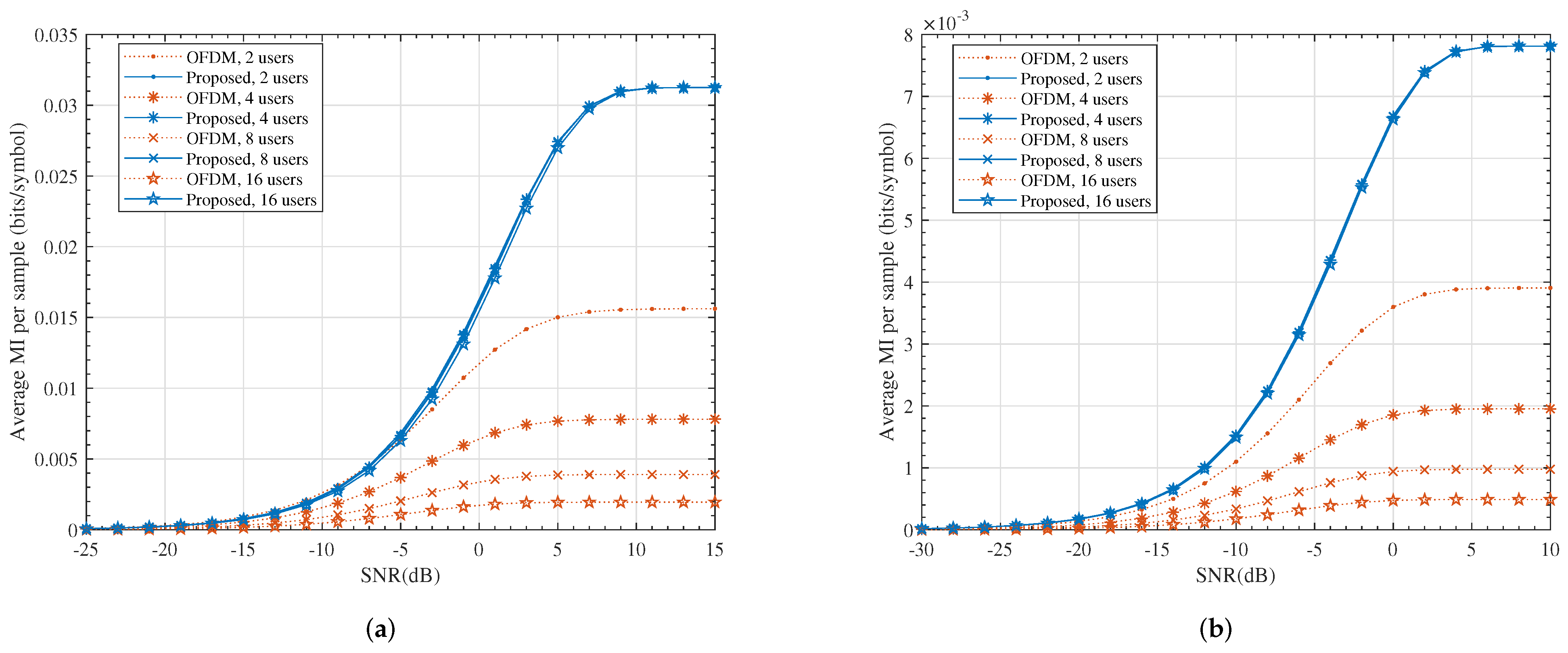
4.3. MI
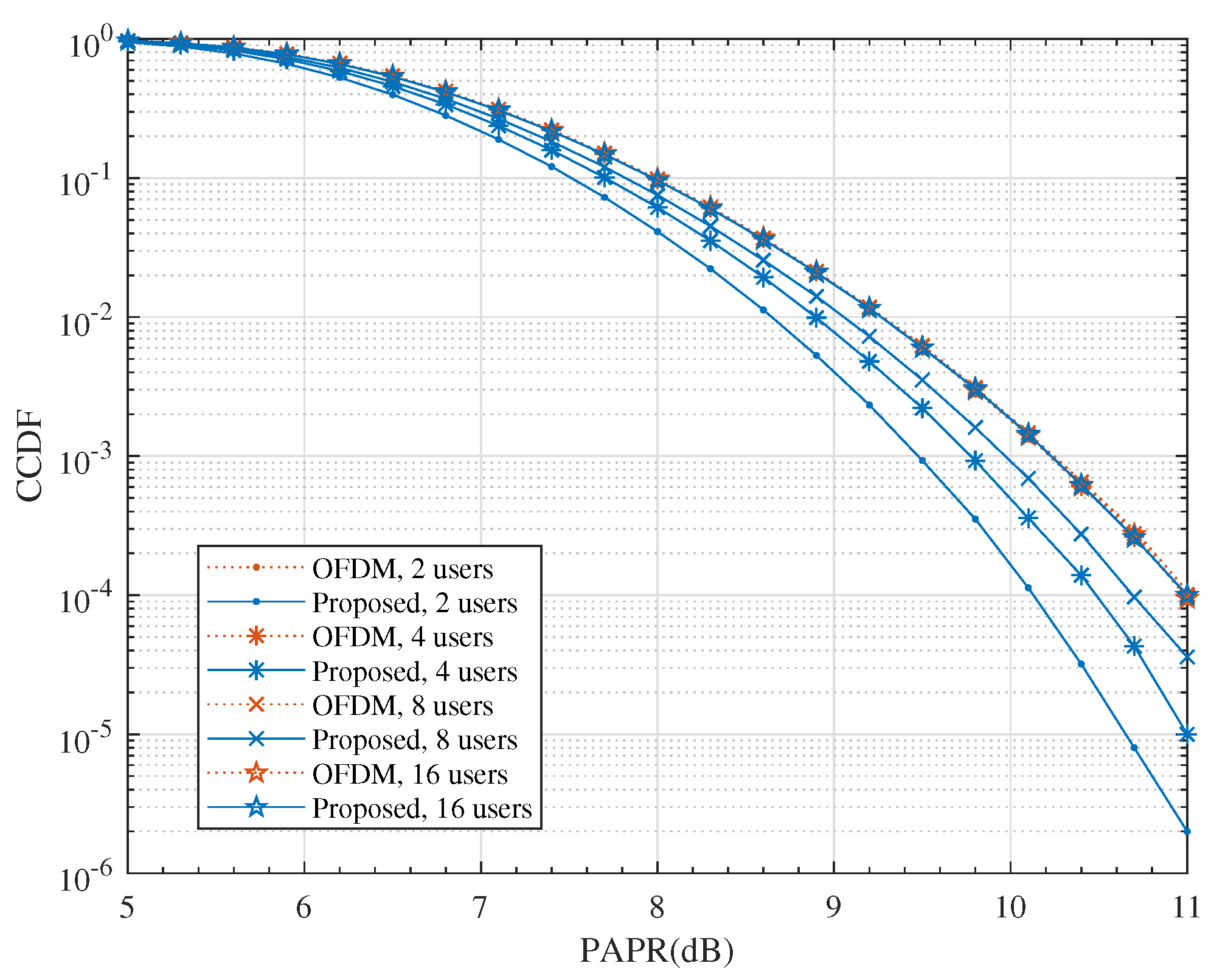
4.4. PAPR
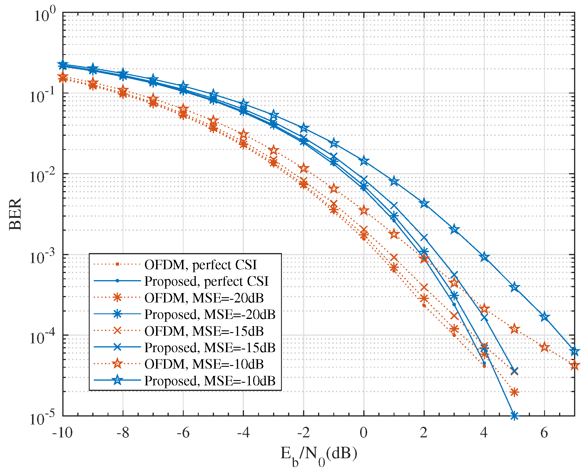
4.5. Imperfect CSI
5. Conclusions
Author Contributions
Funding
Conflicts of Interest
References
- Verma, S.; Kaur, S.; Khan, M.A.; Sehdev, P.S. Toward Green Communication in 6G-Enabled Massive Internet of Things. IEEE Internet Things J. 2020, 8, 5408–5415. [Google Scholar] [CrossRef]
- Chen, X.; Feng, Z.; Wei, Z.; Zhang, P.; Yuan, X. Code-Division OFDM Joint Communication and Sensing System for 6G Machine-Type Communication. IEEE Internet Things J. 2021, 8, 12093–12105. [Google Scholar] [CrossRef]
- Zhang, Z.; Xiao, Y.; Ma, Z.; Xiao, M.; Ding, Z.; Lei, X.; Karagiannidis, G.K.; Fan, P. 6G Wireless Networks: Vision, Requirements, Architecture, and Key Technologies. IEEE Veh. Technol. Mag. 2019, 14, 28–41. [Google Scholar] [CrossRef]
- Juwono, F.H.; Reine, R. Future OFDM-based Communication Systems Towards 6G and Beyond: Machine Learning Approaches. Green Intell. Syst. Appl. 2021, 1, 19–25. [Google Scholar] [CrossRef]
- Liyanaarachchi, S.D.; Riihonen, T.; Barneto, C.B.; Valkama, M. Optimized Waveforms for 5G-6G Communication with Sensing: Theory, Simulations and Experiments. IEEE Trans. Wirel. Commun. 2021, 20, 8301–8315. [Google Scholar] [CrossRef]
- Eren, T.; Akan, A. Null Subcarrier Index Modulation in OFDM Systems for 6G and Beyond. Sensors 2021, 21, 7263. [Google Scholar] [CrossRef]
- Nuss, B.; Mayer, J.; Marahrens, S.; Zwick, T. Frequency Comb OFDM Radar System with High Range Resolution and Low Sampling Rate. IEEE Trans. Microw. Theory Tech. 2020, 68, 3861–3871. [Google Scholar] [CrossRef]
- Rial, R.B.; Rusu, C.; Alkhateeb, A.; Prelcic, N.G.; Heath, R.W. Channel estimation and hybrid combining for mmWave: Phase shifters or switches? In Proceedings of the 2015 Information Theory and Applications Workshop (ITA), San Diego, CA, USA, 1–6 February 2015; pp. 90–97. [Google Scholar]
- Srivastav, P.S.; Chen, L.; Wahla, A.H. On the Performance of Efficient Channel Estimation Strategies for Hybrid Millimeter Wave MIMO System. Entropy 2020, 22, 1121. [Google Scholar] [CrossRef]
- Le, B.; Rondeau, T.W.; Reed, J.H.; Bostian, C.W. Analog-to-digital converters. IEEE Signal Process. Mag. 2005, 22, 69–77. [Google Scholar]
- Yu, S.; Liu, X.; Cao, J.; Zhang, Y. Low-Resolution ADCs for Two-Hop Massive MIMO Relay System under Rician Channels. Entropy 2021, 23, 1074. [Google Scholar] [CrossRef]
- Risi, C.; Persson, D.; Larsson, E.G. Massive MIMO with 1-bit ADC. Massive MIMO with 1-bit ADC. arXiv 2014, arXiv:1404.7736. [Google Scholar]
- Gao, H.; Xiao, K.; Xia, B.; Chen, Z. Mutual Information Analysis of Mixed-ADC MIMO Systems over Rayleigh Channels Based on Random Matrix Theory. IEEE Trans. Wirel. Commun. 2020, 19, 4894–4906. [Google Scholar] [CrossRef]
- Zhang, M.; Tan, W.; Gao, J.; Jin, S. Spectral efficiency and power allocation for mixed-ADC massive MIMO system. China Commun. 2014, 15, 112–127. [Google Scholar] [CrossRef]
- Zhang, T.; Wen, C.; Jin, S.; Jiang, T. Mixed-ADC Massive MIMO Detectors: Performance Analysis and Design Optimization. IEEE Trans. Wirel. Commun. 2016, 15, 7738–7752. [Google Scholar] [CrossRef] [Green Version]
- Xiong, Y.; Wei, N.; Zhang, Z. A Low-Complexity Iterative GAMP-Based Detection for Massive MIMO with Low-Resolution ADCs. In Proceedings of the 2017 IEEE Wireless Communications and Networking Conference (WCNC), San Francisco, CA, USA, 19–22 March 2017; pp. 1–6. [Google Scholar]
- Wen, C.; Wang, C.; Jin, S.; Wang, K.; Ting, P. Bayes-optimal joint channel-and-data estimation for massive MIMO with low-precision ADCs. IEEE Trans. Signal Process. 2015, 64, 2541–2556. [Google Scholar] [CrossRef] [Green Version]
- Sun, P.; Liu, F.; Cui, J.; Wang, W.; Ye, Y.; Wang, Z. A Joint Symbol-Detection, Channel-Estimation and Decoding Scheme under Few-Bit ADCs in mmWave Communications. Sensors 2020, 20, 1857. [Google Scholar] [CrossRef] [PubMed] [Green Version]
- Cheng, X.; Xia, B.; Xu, K.; Li, S. Bayesian Channel Estimation and Data Detection in Oversampled OFDM Receiver with Low-Resolution ADC. IEEE Trans. Wirel. Commun. 2021, 20, 5558–5571. [Google Scholar] [CrossRef]
- Zou, Q.; Zhang, H.; Cai, D.; Yang, H. A Low-Complexity Joint User Activity, Channel and Data Estimation for Grant-Free Massive MIMO Systems. IEEE Signal Process. Lett. 2021, 27, 1290–1294. [Google Scholar] [CrossRef]
- Wei, C.; Liu, H.; Lin, C.; Chi, S. Analog-to-digital conversion using sub-Nyquist sampling rate in flexible delay-division multiplexing OFDMA PONs. J. Light. Technol. 2016, 34, 2381–2390. [Google Scholar] [CrossRef]
- Yu, S.; Huang, P.; Lin, C.; Lin, C.; Wei, C.; Chi, S. Broadband Wired and Wireless Access System with Novel Sub-Nyquist Sampling-Rate ADC Receiver. In Proceedings of the 2020 Opto-Electronics and Communications Conference (OECC), Taipei, Taiwan, 4–8 October 2020; pp. 1–2. [Google Scholar]
- Chen, W.; Yu, M.; Yang, L.; Wei, C.; Lin, C. Low-bandwidth sub-nyquist A/D conversion in delay-division multiplexing OFDM PONs enabled by optical shaping. In Proceedings of the 2020 Optical Fiber Communications Conference and Exhibition (OFC), San Diego, CA, USA, 8–12 March 2020; pp. 1–3. [Google Scholar]
- Chiu, M.; Wu, W.; Chao, C. Frequency-diversity coded OFDM for ultra-wideband systems with under-sampling-rate receivers. In Proceedings of the IEEE International Conference on Communication, Seoul, Korea, 16–20 May 2005; pp. 2852–2856. [Google Scholar]
- Liu, H.; Lin, C.; Lin, C.; Wei, C.; Huang, H.; Hsu, H.; Wu, M.; Chi, S. Simple receiving scheme in 100-GHz DD OFDM RoF systems employing low-sampling-rate ADCs and digital preprocess. In Proceedings of the 2015 Optical Fiber Communications Conference and Exhibition (OFC), Los Angeles, CA, USA, 22–26 March 2015; pp. 1–3. [Google Scholar]
- Ponnuru, S.; Seo, M.; Madhow, U.; Rodwell, M. Joint Mismatch and Channel Compensation for High-Speed OFDM Receivers with Time-Interleaved ADCs. IEEE Trans. Commun. 2010, 58, 2391–2401. [Google Scholar] [CrossRef]
- Lin, C.; Lin, C.; Wei, C.; Chi, S. DFT/IDFT-free receiving scheme for spread-OFDM signals employing low-sampling-rate ADCs. Opt. Express 2017, 25, 27750–27757. [Google Scholar] [CrossRef] [PubMed] [Green Version]
- Ting, P.; Yu, S.; Huang, Z.; Wei, C.; Chi, S.; Lin, C. Fronthaul Optical Links Using Sub-Nyquist Sampling Rate ADC for B5G/6G Sub-THz Ma-MIMO Beamforming. IEEE Access 2021, 10, 236–243. [Google Scholar] [CrossRef]
- Liu, Y.; Yan, J.J.; Dabag, H.T.; Asbeck, P.M. Novel Technique for Wideband Digital Predistortion of Power Amplifiers with an Under-Sampling ADC. IEEE Trans. Microw. Theory Tech. 2014, 62, 2604–2617. [Google Scholar] [CrossRef]
- Cheng, L.; Liu, X.; Chard, N.; Effenberger, F.; Chang, G. Experimental Demonstration of Sub-Nyquist Sampling for Bandwidth- and Hardware-Efficient Mobile Fronthaul Supporting 128 × 128 MIMO with 100-MHz OFDM Signals. In Proceedings of the Optical Fiber Communication Conference, Anaheim, CA, USA, 20–24 March 2016; pp. 1–3. [Google Scholar]
- Sohrabi, F.; Yu, W. Hybrid Analog and Digital Beamforming for mmWave OFDM Large-Scale Antenna Arrays. IEEE J. Sel. Areas Commun. 2017, 35, 1432–1443. [Google Scholar] [CrossRef] [Green Version]
- Zhao, L.; Zhao, H.; Zheng, K.; Xiang, W. Massive MIMO in 5G Networks: Selected Applications; Springer International Publishing: Cham, Switzerland, 2018. [Google Scholar]
- Goldsmith, A. Wireless Communications; Cambridge University Press: Cambridge, UK, 2005. [Google Scholar]
- Yang, P.; Cheng, J.; Yang, H. Evaluation of the Mutual Information of MIMO Channel with Finite-Alphabet Inputs. In Proceedings of the 2019 IEEE 30th Annual International Symposium on Personal, Indoor and Mobile Radio Communications (PIMRC), Istanbul, Turkey, 8–11 September 2019; pp. 1–6. [Google Scholar]
- Xin, R.; Ni, Z.; Wu, S.; Kuang, L.; Jiang, C. Low-complexity joint channel estimation and symbol detection for OFDMA systems. China Commun. 2019, 16, 49–60. [Google Scholar] [CrossRef]
- Jiang, Y.; Varanasi, M.K.; Li, J. Performance analysis of ZF and MMSE equalizers for MIMO systems: An in-depth study of the high SNR regime. IEEE Trans. Inf. Theory 2011, 57, 2008–2026. [Google Scholar] [CrossRef] [Green Version]
- Li, A.; Spano, D.; Krivochiza, J.; Domouchtsidis, S.; Tsinos, C.G.; Masouros, C.; Chatzinotas, S.; Li, Y.; Vucetic, B.; Ottersten, B. A tutorial on interference exploitation via symbol-level precoding: Overview, state-of-the-art and future directions. IEEE Commun. Surv. Tutor. 2020, 22, 796–839. [Google Scholar] [CrossRef]
- Pramono, S.; Triyono, E.; Subagio, B.B. Performance of Leakage Based Precoding Scheme for Minimizing Interference. J. Commun. 2020, 15, 214–220. [Google Scholar] [CrossRef]
Publisher’s Note: MDPI stays neutral with regard to jurisdictional claims in published maps and institutional affiliations. |
© 2022 by the authors. Licensee MDPI, Basel, Switzerland. This article is an open access article distributed under the terms and conditions of the Creative Commons Attribution (CC BY) license (https://creativecommons.org/licenses/by/4.0/).
Share and Cite
Ou, Z.; Liu, X.; Yang, H. A Low Sampling Rate Receiver Design for Multi-Antenna Multi-User OFDM Systems. Entropy 2022, 24, 448. https://doi.org/10.3390/e24040448
Ou Z, Liu X, Yang H. A Low Sampling Rate Receiver Design for Multi-Antenna Multi-User OFDM Systems. Entropy. 2022; 24(4):448. https://doi.org/10.3390/e24040448
Chicago/Turabian StyleOu, Zeliang, Xiaofeng Liu, and Hongwen Yang. 2022. "A Low Sampling Rate Receiver Design for Multi-Antenna Multi-User OFDM Systems" Entropy 24, no. 4: 448. https://doi.org/10.3390/e24040448
APA StyleOu, Z., Liu, X., & Yang, H. (2022). A Low Sampling Rate Receiver Design for Multi-Antenna Multi-User OFDM Systems. Entropy, 24(4), 448. https://doi.org/10.3390/e24040448