


First Request First Service Entanglement Routing Scheme for Quantum Networks
 , , and
Abstract
1. Introduction
2. Preliminaries
3. Modeling for Entanglement Distribution Network
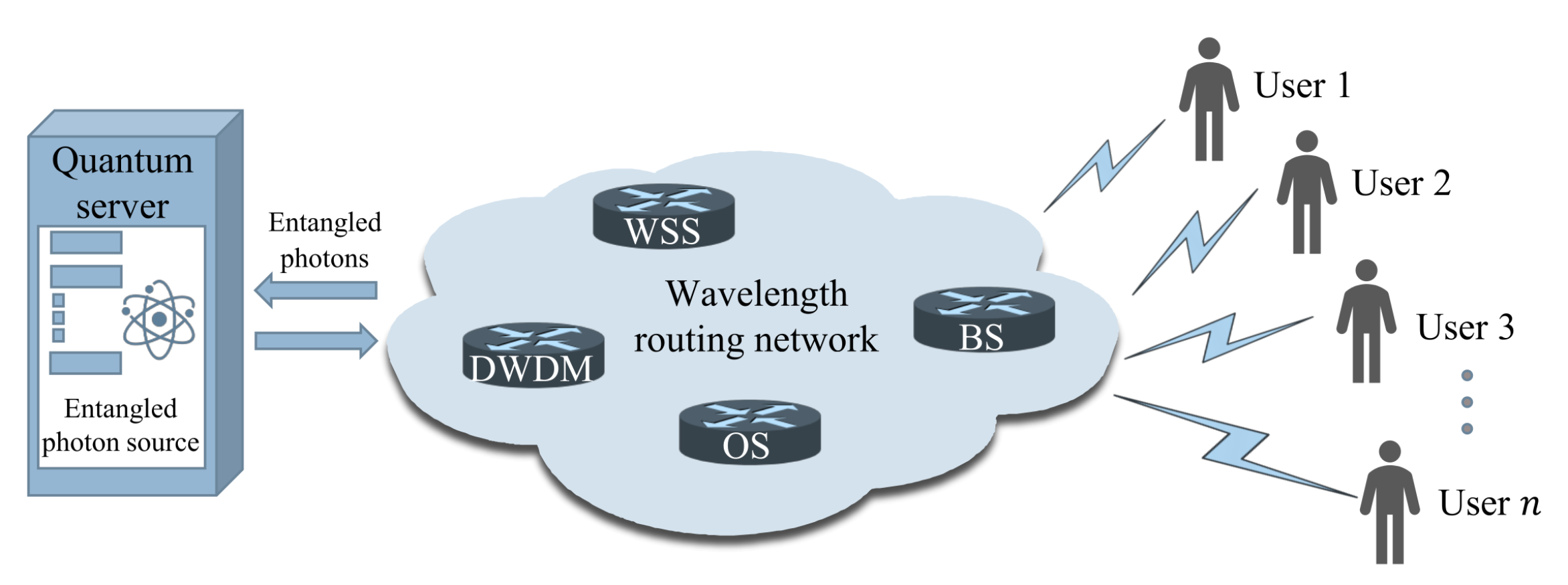
3.1. Network Components
- Quantum server. A quantum server provides and controls the wavelength switching of entangled photons.
- Wavelength routing network. A wavelength routing network is responsible for dividing the entangled bandwidth into multiple wavelength channels and routing them to distant users with OS, WSS, and other wavelength switching devices.
- Users. Users perform various protocols to generate secure keys, synchronize their clocks and so on.
3.2. Modeling of Nodes
3.3. Modeling of Edges
3.4. Instantiation
4. First Request First Service Entanglement Routing Scheme
4.1. The Proposed FRFS Scheme
4.2. The Modified Dijkstra Algorithm
4.3. Complexity Analysis
5. Evaluation Results
5.1. Evaluation on T/W-DM Networks
5.2. Evaluation with Different Sequences of Requests from Users
5.3. Evaluation on Large-Scale and Dynamic Networks
6. Conclusions
Author Contributions
Funding
Institutional Review Board Statement
Informed Consent Statement
Data Availability Statement
Conflicts of Interest
Abbreviations
| FRFS | First request first service |
| DWDM | Dense wavelength division multiplexer |
| WSS | Wavelength selective switches |
| BS | Beam splitter |
| OS | Optical switch |
| AOS | All-pass optical switch |
| TDM | Time division multiplexing |
| WDM | Wavelength division multiplexing |
| ITU | International Telecommunication Union |
References
- Kimble, H.J. The quantum internet. Nature 2008, 453, 1023–1030. [Google Scholar] [CrossRef] [PubMed]
- Shi, S.; Qian, C. Concurrent entanglement routing for quantum networks: Model and designs. In Proceedings of the Annual Conference of the ACM Special Interest Group on Data Communication on the Applications, Technologies, Architectures, and Protocols for Computer Communication, Virtual Event, USA, 10–14 August 2020; pp. 62–75. [Google Scholar]
- Pompili, M.; Hermans, S.L.N.; Baier, S.; Beukers, H.K.C.; Humphreys, P.C.; Schouten, R.N.; Vermeulen, R.F.L.; Tiggelman, M.J.; dos Santos Martins, L.; Dirkse, B.; et al. Realization of a multinode quantum network of remote solid-state qubits. Science 2021, 372, 259–264. [Google Scholar] [CrossRef]
- Riedinger, R.; Wallucks, A.; Marinković, I.; Löschnauer, C.; Aspelmeyer, M.; Hong, S.; Gröblacher, S. Remote quantum entanglement between two micromechanical oscillators. Nature 2018, 556, 473–477. [Google Scholar] [CrossRef] [PubMed]
- Dahlberg, A.; Skrzypczyk, M.; Coopmans, T.; Wubben, L.; Rozpędek, F.; Pompili, M.; Stolk, A.; Pawełczak, P.; Knegjens, R.; de Oliveira Filho, J. A link layer protocol for quantum networks. In Proceedings of the ACM Special Interest Group on Data Communication, Beijing, China, 19–23 August 2019; pp. 159–173. [Google Scholar]
- Qi, Z.; Li, Y.; Huang, Y.; Feng, J.; Zheng, Y.; Chen, X. A 15-user quantum secure direct communication network. Light. Sci. Appl. 2021, 10, 183. [Google Scholar] [CrossRef]
- Huang, Z.; Joshi, S.K.; Aktas, D.; Lupo, C.; Quintavalle, A.O.; Venkatachalam, N.; Wengerowsky, S.; Lončarić, M.; Neumann, S.P.; Liu, B.; et al. Experimental implementation of secure anonymous protocols on an eight-user quantum key distribution network. Npj Quantum Inf. 2022, 8, 25. [Google Scholar] [CrossRef]
- Paraïso, T.K.; Roger, T.; Marangon, D.G.; De Marco, I.; Sanzaro, M.; Woodward, R.I.; Dynes, J.F.; Yuan, Z.; Shields, A.J. A photonic integrated quantum secure communication system. Nat. Photonics 2021, 15, 850–856. [Google Scholar] [CrossRef]
- Qi, R.; Sun, Z.; Lin, Z.; Niu, P.; Hao, W.; Song, L.; Huang, Q.; Gao, J.; Yin, L.; Long, G.L. Implementation and security analysis of practical quantum secure direct communication. Light. Sci. Appl. 2019, 8, 22. [Google Scholar] [CrossRef] [PubMed]
- Pirandola, S.; Andersen, U.L.; Banchi, L.; Berta, M.; Bunandar, D.; Colbeck, R.; Englund, D.; Gehring, T.; Lupo, C.; Ottaviani, C.; et al. Advances in quantum cryptography. Adv. Opt. Photonics 2020, 12, 1012–1236. [Google Scholar] [CrossRef]
- Cavaliere, F.; Prati, E.; Poti, L.; Muhammad, I.; Catuogno, T. Secure Quantum Communication Technologies and Systems: From Labs to Markets. Quantum Rep. 2020, 2, 80–106. [Google Scholar] [CrossRef]
- Shahandeh, F.; Lund, A.P.; Ralph, T.C. Quantum correlations and global coherence in distributed quantum computing. Phys. Rev. A 2019, 99, 052303. [Google Scholar] [CrossRef]
- Cuomo, D.; Caleffi, M.; Cacciapuoti, A.S. Towards a distributed quantum computing ecosystem. IET Quantum Commun. 2020, 1, 3–8. [Google Scholar] [CrossRef]
- Cacciapuoti, A.S.; Caleffi, M.; Tafuri, F.; Cataliotti, F.S.; Gherardini, S.; Bianchi, G. Quantum Internet: Networking Challenges in Distributed Quantum Computing. IEEE Netw. 2020, 34, 137–143. [Google Scholar] [CrossRef]
- Hong, H.; Quan, R.; Xiang, X.; Xue, W.; Quan, H.; Zhao, W.; Liu, Y.; Cao, M.; Liu, T.; Zhang, S.; et al. Demonstration of 50 Km Fiber-Optic Two-Way Quantum Clock Synchronization. J. Light. Technol. 2022, 40, 3723–3728. [Google Scholar] [CrossRef]
- Ilo-Okeke, E.O.; Tessler, L.; Dowling, J.P.; Byrnes, T. Entanglement-based quantum clock synchronization. AIP Conf. Proc. 2020, 2241, 020011. [Google Scholar] [CrossRef]
- Quan, R.; Hong, H.; Xue, W.; Quan, H.; Zhao, W.; Xiang, X.; Liu, Y.; Cao, M.; Liu, T.; Zhang, S.; et al. Implementation of field two-way quantum synchronization of distant clocks across a 7 km deployed fiber link. Opt. Express 2022, 30, 10269–10279. [Google Scholar] [CrossRef]
- Proctor, T.J.; Knott, P.A.; Dunningham, J.A. Multiparameter Estimation in Networked Quantum Sensors. Phys. Rev. Lett. 2018, 120, 080501. [Google Scholar] [CrossRef]
- Guo, X.; Breum, C.R.; Borregaard, J.; Izumi, S.; Larsen, M.V.; Gehring, T.; Christandl, M.; Neergaard-Nielsen, J.S.; Andersen, U.L. Distributed quantum sensing in a continuous-variable entangled network. Nat. Phys. 2020, 16, 281–284. [Google Scholar] [CrossRef]
- Zhang, Z.; Zhuang, Q. Distributed quantum sensing. Quantum Sci. Technol. 2021, 6, 043001. [Google Scholar] [CrossRef]
- Elliott, C.; Pearson, D.; Troxel, G. Quantum Cryptography in Practice; Association for Computing Machinery: New York, NY, USA, 2003; SIGCOMM ’03; pp. 227–238. [Google Scholar] [CrossRef]
- Chip, E.; Alexander, C.; David, P.; Oleksiy, P.; John, S.; Henry, Y. Current status of the DARPA quantum network. Proc. SPIE 2005, 5815, 138–149. [Google Scholar] [CrossRef]
- Peev, M.; Poppe, A.; Maurhart, O.; Lorunser, T.; Langer, T.; Pacher, C. The SECOQC Quantum Key Distribution Network in Vienna. In Proceedings of the 2009 35th European Conference on Optical Communication, Vienna, Austria, 20–24 September 2009; pp. 1–4. [Google Scholar]
- Sasaki, M.; Fujiwara, M.; Ishizuka, H.; Klaus, W.; Wakui, K.; Takeoka, M.; Miki, S.; Yamashita, T.; Wang, Z.; Tanaka, A.; et al. Field test of quantum key distribution in the Tokyo QKD Network. Opt. Express 2011, 19, 10387–10409. [Google Scholar] [CrossRef]
- Chen, Y.A.; Zhang, Q.; Chen, T.Y.; Cai, W.Q.; Liao, S.K.; Zhang, J.; Chen, K.; Yin, J.; Ren, J.G.; Chen, Z.; et al. An integrated space-to-ground quantum communication network over 4600 kilometres. Nature 2021, 589, 214–219. [Google Scholar] [CrossRef]
- Wehner, S.; Elkouss, D.; Hanson, R. Quantum internet: A vision for the road ahead. Science 2018, 362, eaam9288. [Google Scholar] [CrossRef]
- Vernaz-Gris, P.; Huang, K.; Cao, M.; Sheremet, A.S.; Laurat, J. Highly-efficient quantum memory for polarization qubits in a spatially-multiplexed cold atomic ensemble. Nat. Commun. 2018, 9, 363. [Google Scholar] [CrossRef] [PubMed]
- Lipka, M.; Mazelanik, M.; Leszczyński, A.; Wasilewski, W.; Parniak, M. Massively-multiplexed generation of Bell-type entanglement using a quantum memory. Commun. Phys. 2021, 4, 46. [Google Scholar] [CrossRef]
- Cao, M.; Hoffet, F.; Qiu, S.; Sheremet, A.S.; Laurat, J. Efficient reversible entanglement transfer between light and quantum memories. Optica 2020, 7, 1440–1444. [Google Scholar] [CrossRef]
- Yu, Y.; Sun, P.F.; Zhang, Y.Z.; Bai, B.; Fang, Y.Q.; Luo, X.Y.; An, Z.Y.; Li, J.; Zhang, J.; Xu, F.; et al. Measurement-Device-Independent Verification of a Quantum Memory. Phys. Rev. Lett. 2021, 127, 160502. [Google Scholar] [CrossRef] [PubMed]
- Wengerowsky, S.; Joshi, S.K.; Steinlechner, F.; Hübel, H.; Ursin, R. An entanglement-based wavelength-multiplexed quantum communication network. Nature 2018, 564, 225–228. [Google Scholar] [CrossRef] [PubMed]
- Joshi Siddarth, K.; Aktas, D.; Wengerowsky, S.; Lončarić, M.; Neumann Sebastian, P.; Liu, B.; Scheidl, T.; Lorenzo Guillermo, C.; Samec, v.; Kling, L.; et al. A trusted node-free eight-user metropolitan quantum communication network. Sci. Adv. 2020, 6, eaba0959. [Google Scholar] [CrossRef]
- Liu, X.; Liu, J.; Xue, R.; Wang, H.; Li, H.; Feng, X.; Liu, F.; Cui, K.; Wang, Z.; You, L.; et al. 40-user fully connected entanglement-based quantum key distribution network without trusted node. PhotoniX 2022, 3, 2. [Google Scholar] [CrossRef]
- Liu, X.; Yao, X.; Xue, R.; Wang, H.; Li, H.; Wang, Z.; You, L.; Feng, X.; Liu, F.; Cui, K.; et al. An entanglement-based quantum network based on symmetric dispersive optics quantum key distribution. APL Photonics 2020, 5, 076104. [Google Scholar] [CrossRef]
- Zhu, E.Y.; Corbari, C.; Gladyshev, A.; Kazansky, P.G.; Lo, H.K.; Qian, L. Toward a reconfigurable quantum network enabled by a broadband entangled source. J. Opt. Soc. Am. B 2019, 36, B1–B6. [Google Scholar] [CrossRef]
- Appas, F.; Baboux, F.; Amanti, M.I.; Lemaítre, A.; Boitier, F.; Diamanti, E.; Ducci, S. Flexible entanglement-distribution network with an AlGaAs chip for secure communications. Npj Quantum Inf. 2021, 7, 118. [Google Scholar] [CrossRef]
- Alshowkan, M.; Williams, B.P.; Evans, P.G.; Rao, N.S.V.; Simmerman, E.M.; Lu, H.H.; Lingaraju, N.B.; Weiner, A.M.; Marvinney, C.E.; Pai, Y.Y.; et al. Reconfigurable Quantum Local Area Network Over Deployed Fiber. PRX Quantum 2021, 2, 040304. [Google Scholar] [CrossRef]
- Lingaraju, N.B.; Lu, H.H.; Seshadri, S.; Leaird, D.E.; Weiner, A.M.; Lukens, J.M. Adaptive bandwidth management for entanglement distribution in quantum networks. Optica 2021, 8, 329–332. [Google Scholar] [CrossRef]
- Wang, R.; Alia, O.; Clark, M.J.; Bahrani, S.; Joshi, S.K.; Aktas, D.; Kanellos, G.T.; Peranić, M.; Lončarić, M.; Stipčević, M.; et al. A Dynamic Multi-Protocol Entanglement Distribution Quantum Network. In Proceedings of the 2022 Optical Fiber Communications Conference and Exhibition (OFC), San Diego, CA, USA, 6–10 March 2022; pp. 1–3. [Google Scholar]
- Nejabati, R.; Wang, R.; Kanellos, G.T.; Simeonidou, D. Optical Network Architecture Supporting Dynamic and End-to-End Quantum Secure Networking. In Proceedings of the 2021 European Conference on Optical Communication (ECOC), Bordeaux, France, 13–16 September 2021; pp. 1–4. [Google Scholar] [CrossRef]
- Wang, R.; Joshi, S.K.; Kanellos, G.T.; Aktas, D.; Rarity, J.; Nejabati, R.; Simeonidou, D. AI-Enabled Large-Scale Entanglement Distribution Quantum Networks. In Proceedings of the Optical Fiber Communication Conference (OFC), Washington, DC, USA, 6–11 June 2021; Dong, P., Kani, J., Xie, C., Casellas, R., Cole, C., Li, M., Eds.; Optica Publishing Group, OSA Technical Digest: Washington, DC, USA, 2021; p. Tu1I.4. [Google Scholar] [CrossRef]
- Pirandola, S.; Braunstein, S.L. Physics: Unite to build a quantum Internet. Nature 2016, 532, 169–171. [Google Scholar] [CrossRef] [PubMed]
- Harney, C.; Pirandola, S. Analytical Methods for High-Rate Global Quantum Networks. PRX Quantum 2022, 3, 010349. [Google Scholar] [CrossRef]
- Solomons, N.R.; Fletcher, A.I.; Aktas, D.; Venkatachalam, N.; Wengerowsky, S.; Lončarić, M.; Neumann, S.P.; Liu, B.; Samec, V.; Stipcčević, M.; et al. Scalable Authentication and Optimal Flooding in a Quantum Network. PRX Quantum 2022, 3, 020311. [Google Scholar] [CrossRef]
- Harney, C.; Fletcher, A.I.; Pirandola, S. End-To-End Capacities of Hybrid Quantum Networks. Phys. Rev. Appl. 2022, 18, 014012. [Google Scholar] [CrossRef]
- Van Meter, R.; Satoh, T.; Ladd, T.D.; Munro, W.J.; Nemoto, K. Path selection for quantum repeater networks. Netw. Sci. 2013, 3, 82–95. [Google Scholar] [CrossRef]
- Pant, M.; Krovi, H.; Towsley, D.; Tassiulas, L.; Jiang, L.; Basu, P.; Englund, D.; Guha, S. Routing entanglement in the quantum internet. Npj Quantum Inf. 2019, 5, 25. [Google Scholar] [CrossRef]
- Schoute, E.; Mancinska, L.; Islam, T.; Kerenidis, I.; Wehner, S. Shortcuts to quantum network routing. arXiv 2016, arXiv:1610.05238. [Google Scholar]
- Cicconetti, C.; Conti, M.; Passarella, A. Request Scheduling in Quantum Networks. IEEE Trans. Quantum Eng. 2021, 2, 2–17. [Google Scholar] [CrossRef]
- Li, C.; Li, T.; Liu, Y.X.; Cappellaro, P. Effective routing design for remote entanglement generation on quantum networks. Npj Quantum Inf. 2021, 7, 10. [Google Scholar] [CrossRef]
- Le, L.; Nguyen, T.N. DQRA: Deep Quantum Routing Agent for Entanglement Routing in Quantum Networks. IEEE Trans. Quantum Eng. 2022, 3, 1–12. [Google Scholar] [CrossRef]
- Lee, Y.; Bersin, E.; Dahlberg, A.; Wehner, S.; Englund, D. A quantum router architecture for high-fidelity entanglement flows in quantum networks. Npj Quantum Inf. 2022, 8, 75. [Google Scholar] [CrossRef]
- Neumann, S.P.; Scheidl, T.; Selimovic, M.; Pivoluska, M.; Liu, B.; Bohmann, M.; Ursin, R. Model for optimizing quantum key distribution with continuous-wave pumped entangled-photon sources. Phys. Rev. A 2021, 104, 022406. [Google Scholar] [CrossRef]
- Ma, X.; Fung, C.H.F.; Lo, H.K. Quantum key distribution with entangled photon sources. Phys. Rev. A 2007, 76, 012307. [Google Scholar] [CrossRef]
- Dynes, J.F.; Wonfor, A.; Tam, W.W.S.; Sharpe, A.W.; Takahashi, R.; Lucamarini, M.; Plews, A.; Yuan, Z.L.; Dixon, A.R.; Cho, J.; et al. Cambridge quantum network. Npj Quantum Inf. 2019, 5, 101. [Google Scholar] [CrossRef]
- Valivarthi, R.; Puigibert, M.l.G.; Zhou, Q.; Aguilar, G.H.; Verma, V.B.; Marsili, F.; Shaw, M.D.; Nam, S.W.; Oblak, D.; Tittel, W. Quantum teleportation across a metropolitan fibre network. Nat. Photonics 2016, 10, 676–680. [Google Scholar] [CrossRef]


| cps | 300 ps | 0.761 | 1.81% | 300 cps | 3 dB |
| Case | Network Type | |||||
|---|---|---|---|---|---|---|
| 1 | TDM | 5 ports WSS | AOS | AOS | AOS | AOS |
| 2 | TDM | 5 ports WSS | OS (1/4in, 2/3out) | OS (1/4in, 2/3out) | OS (1/2in, 3/4out) | OS (1/2in, 3/4out) |
| 3 | TDM + WDM | 5 ports WSS | 5 ports WSS | 5 ports WSS | 5 ports WSS | 5 ports WSS |
| 4 | TDM + WDM | 5 ports WSS | 5 ports WSS | OS (1/4in, 2/3out) | AOS | AOS |
| 5 | TDM + WDM | DWDM | DWDM | AOS | AOS | AOS |
| Case | Path | (dB) | (dB) | (kcps) | (cps) |
|---|---|---|---|---|---|
| 1 | 11.6 | 25.8 | 20.82 | 332.99 | |
| 2 | 11.1 | 27.5 | 15.80 | 251.85 | |
| 3 | 15.6 | 31.2 | 2.39 | 37.63 | |
| 4 | 15.6 | 25.3 | 9.30 | 148.79 | |
| 5 | 28.2 | 22.3 | 1.02 | 16.19 |
| Request Sequence | ||||||
|---|---|---|---|---|---|---|
| 1 | AB | AC | AD | CD | BD | BC |
| 2 | AC | AB | CD | AD | BC | BD |
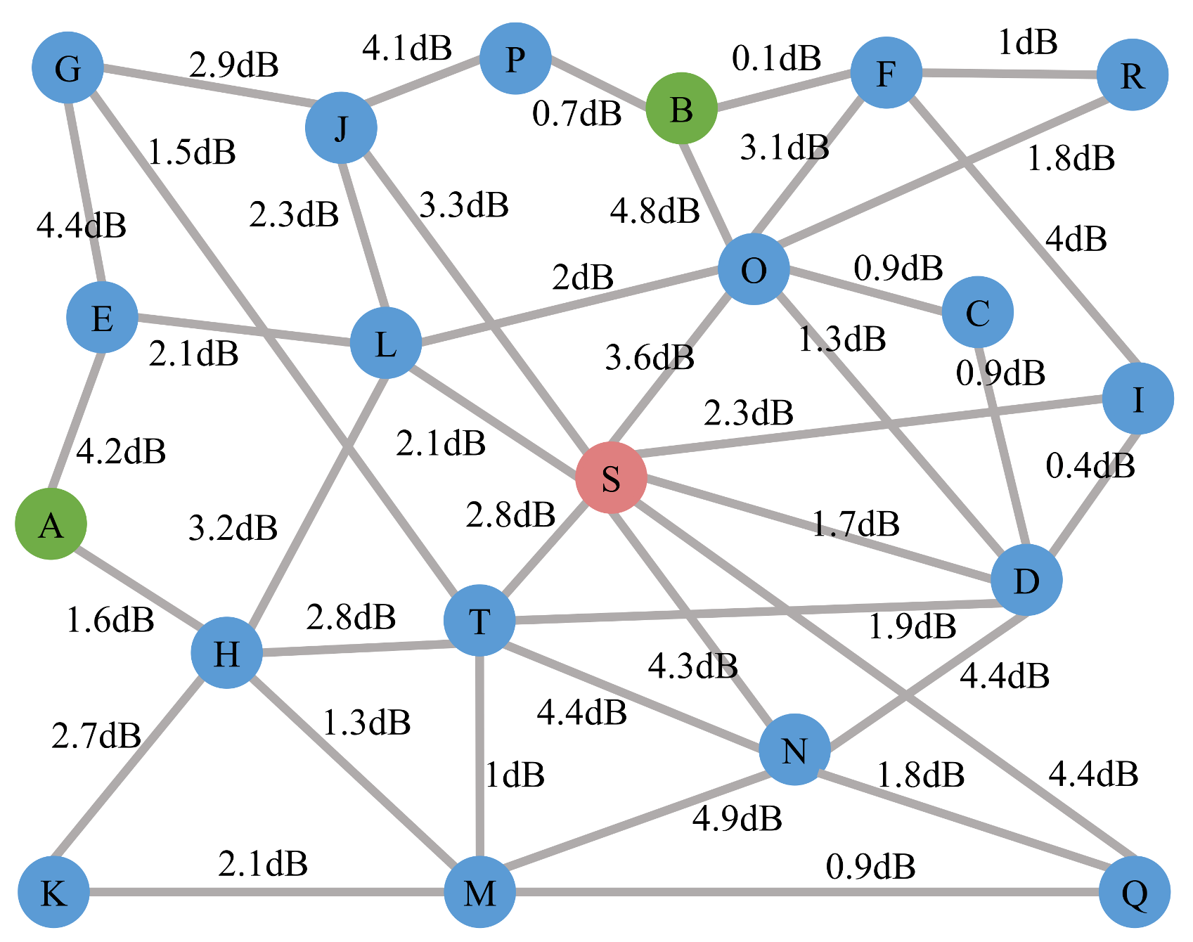
| Case | Path | (dB) | (dB) | (kcps) | (cps) |
|---|---|---|---|---|---|
| G | AHLSOB | 21.9 | 18.4 | 10.68 | 171.26 |
| G- | AELSOB | 23.4 | 18.4 | 7.56 | 121.12 |
| G- | AHLSIFB | 21.9 | 21.4 | 5.35 | 85.74 |
| G- | AHTSOB | 22.2 | 18.4 | 9.97 | 159.80 |
Publisher’s Note: MDPI stays neutral with regard to jurisdictional claims in published maps and institutional affiliations. |
© 2022 by the authors. Licensee MDPI, Basel, Switzerland. This article is an open access article distributed under the terms and conditions of the Creative Commons Attribution (CC BY) license (https://creativecommons.org/licenses/by/4.0/).
Share and Cite
Li, S.-C.; Tang, B.-Y.; Zhou, H.; Yu, H.-C.; Liu, B.; Yu, W.-R.; Liu, B. First Request First Service Entanglement Routing Scheme for Quantum Networks. Entropy 2022, 24, 1404. https://doi.org/10.3390/e24101404
Li S-C, Tang B-Y, Zhou H, Yu H-C, Liu B, Yu W-R, Liu B. First Request First Service Entanglement Routing Scheme for Quantum Networks. Entropy. 2022; 24(10):1404. https://doi.org/10.3390/e24101404
Chicago/Turabian StyleLi, Si-Chen, Bang-Ying Tang, Han Zhou, Hui-Cun Yu, Bo Liu, Wan-Rong Yu, and Bo Liu. 2022. "First Request First Service Entanglement Routing Scheme for Quantum Networks" Entropy 24, no. 10: 1404. https://doi.org/10.3390/e24101404
APA StyleLi, S.-C., Tang, B.-Y., Zhou, H., Yu, H.-C., Liu, B., Yu, W.-R., & Liu, B. (2022). First Request First Service Entanglement Routing Scheme for Quantum Networks. Entropy, 24(10), 1404. https://doi.org/10.3390/e24101404