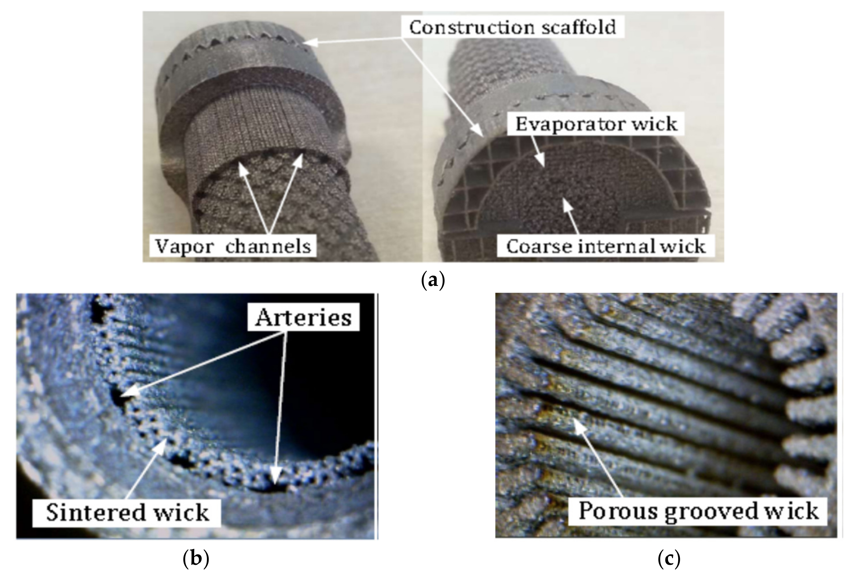
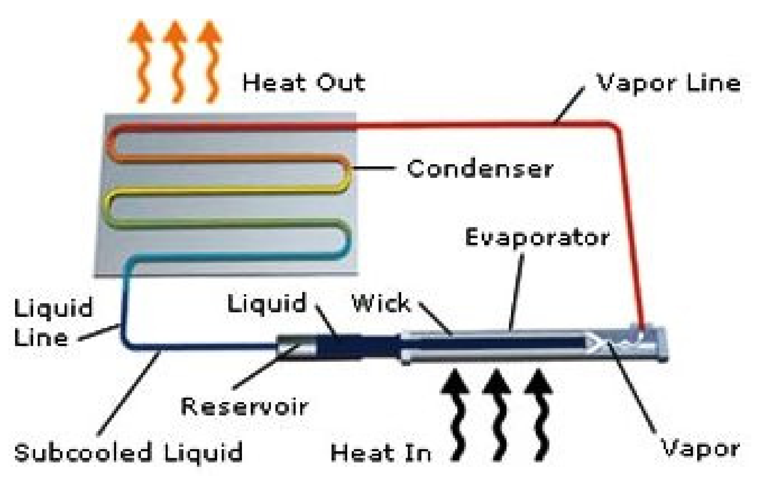
Recent Advances in Loop Heat Pipes with Flat Evaporator
Abstract
:1. Introduction
- −
- Sensitivity to internal fluid saturation pressure that can potentially cause stress, deformation and consequently the ballooning of the evaporator wall and wick, which can lead to the deterioration of the heat input surface contact with the heat source and loss of thermal connection between the heat input wall and the wick. The high positive saturation pressure created by certain working fluids in the evaporator may distort the evaporator casing shape or wick structure. Such a circumstance requires a more conscientious design of evaporator casing which might result in an increase in the wall thickness, increase mass or limit the choice of the working fluid, which may restrict the choice of casing materials [4,6].
- −
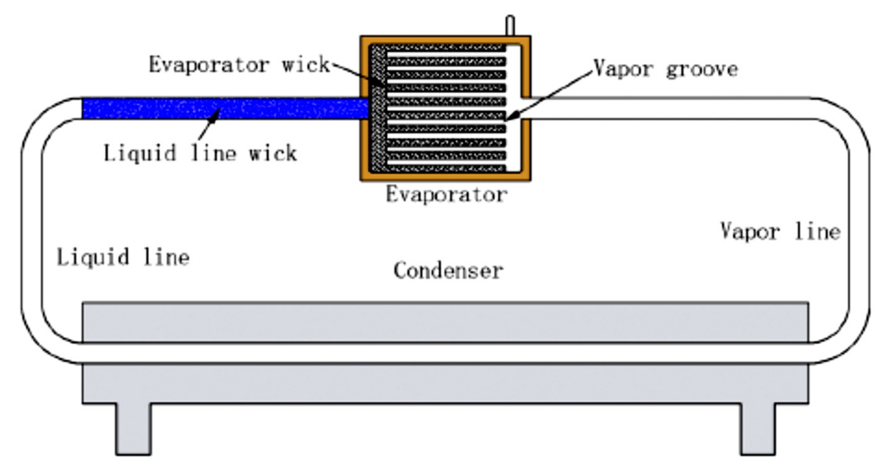
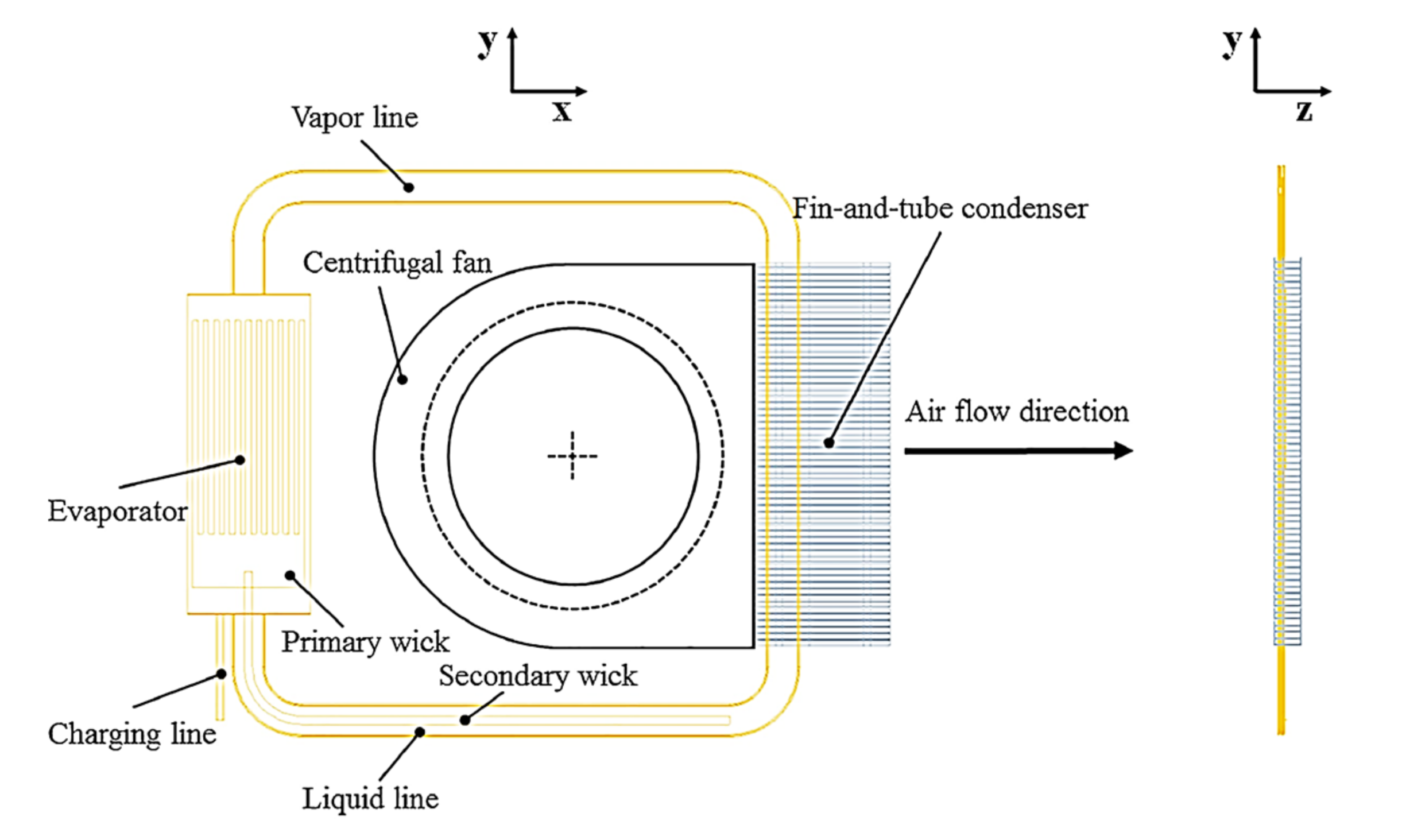
- Increased heat leakage (i.e., “parasitic heating”) from the evaporator heating zone and sidewall into the compensation chamber (CC), which results in the increase of the CC temperature and consequently the LHP resistance and frequent failures in the start-up, especially at low heat loads. The construction of a flat-shaped evaporator requires installation of the heating zone very close to CC, which promotes parasitic heating from the evaporator to CC, therefore is a challenge to overcome. Furthermore, the flat-shaped evaporators have a larger sidewall area which facilitates conduction, resulting in a rise in CC temperature. This reduces the overall thermal performance of the LHP and may also cause a failure in the LHP start-up at a low heat load. A novel mechanical and thermal design of the evaporator can be considered to overcome this challenge [6]. For example, this effect can be reduced by: (1) increasing heat exchange intensity in the evaporation zone; (2) decreasing thermal resistance of the evaporator wall through which the heat load is supplied; and/or (3) by enhancing heat exchange to the working fluid at the wall-wick boundary.
- −
- −
- −
- Difficult start-up at: (1) low operating temperature (due to low vapor pressure) [1]; (2) high g-loads or restarting after the high-g load period. High g-load conditions might cause a reverse flow of working fluid that influence LHP start-up and restart after start-up or situations where the working fluid stalls in the condenser, causing the onset of evaporator dry-out; (3) when LHP is orientated against gravity, that affects the liquid charge and CC size.
- −
- Customizing of new wick properties and construction of new wick profiles to build ultra-performance LHP designs, understanding the manufacturing process;
- −
- Maximizing the distance of the liquid motion in the wick;
- −
- Organization of effective heat exchange during the evaporation and condensation of the working fluid;
- −
- Maximizing the heat transport distance.
2. Novel Wick Materials, Wick Properties and Wick Construction
2.1. Bi-Porous Wicks
2.2. Additive Manufactured Wicks and LHPs
2.3. Wick Surface Treatment
2.4. Non-Metallic and Composite Wicks
3. Working Fluid
Nanofluids
4. Modification in Construction of LHP
5. Miniature Flat LHP
6. Conclusions
- −
- Sensitivity to internal pressure the internal pressure causes stress, deformation and consequently ballooning of the evaporator wall and wick and deterioration of the heating surface contact and loss of thermal connection between the heat input wall and the wick;
- −
- Increased heat leakage from the evaporator heating zone and sidewall into the compensation chamber (CC), which results in the increase of the CC temperature and consequently the LHP resistance and frequent failures in the start-ups;
- −
- Increased heat leakage through the wick into the liquid bore, causing the increased temperature of the liquid being supplied to the evaporator and consequently failure of start-ups;
- −
- Increased possibility of reverse flow of vapor through the joints between the wick and casing into the compensation chamber and/or through the wick in applications where the wick thickness is reduced;
- −
- The difficulty of sealing the casing/wick structure with long edges needs a special mechanical treatment. This causes leakage of the installation in long term maintenance and consequently the failure of the flat evaporator LHP’s operation and limits the use in space and terrestrial applications.
- −
- The creation of novel wick properties or construction techniques that improves the heat transfer capability of the overall LHP, decrease the effect of heat leak through the wick to CC, improve LHP operation reliability and stability, improve the start-up time at low operating temperatures or low operating power, overcome deformation of the evaporator and maximize heat transfer distance. Furthermore, innovative wicks can strongly enhance the LHP heat transfer performance, thermal conductivity as the wicks have greater wettability. The wick treatment improves hardness and hence prevent deformation of flat evaporator LHPs;
- −
- Utilization of novel LHP manufacturing techniques (i.e., AM) allows the development of efficient devices with complex geometry and high surface area to volume ratio (A/V) in order to maximize the interaction between the heat source and heat sink or to maximize the surface area for evaporation/condensation processes and fabrication of products with a lower cost-to-complexity ratio and quicker production time compared to other manufacturing processes and gives the possibility of producing customized and complex freeform shapes, which are in LHPs. Furthermore, the utilization of novel LHP manufacturing techniques overcomes the above-presented challenge of sealing casing/wick that causes leakage and consequently the failure of the LHP;
- −
- The creation of novel wick materials helps to reduce the parasitic heating from the evaporator heating zone and sidewall into CC and hence improves the LHP start up-time;
- −
- The selection of novel working fluids (i.e., nanofluids) significantly improves the heat transfer performance of the LHP;
- −
- The modification of the construction of a flat evaporator LHP may overcome start-up difficulties caused by the temperature overshoot at the start-up period, especially at low heat loads and might reduce or even eliminate a parasitic heal leakage in the evaporator;
- −
- The utilization of novel manufacturing techniques increases the potential of LHP miniaturization and the possibility for dissipating high heat fluxes to take advantage of the passive cooling systems for electronic devices in multiple applications.
Author Contributions
Funding
Institutional Review Board Statement
Informed Consent Statement
Data Availability Statement
Conflicts of Interest
References
- Maydanik, Y.F. Loop heat pipes. Appl. Therm. Eng. 2005, 25, 635–657. [Google Scholar] [CrossRef]
- Siedel, B.; Sartre, V.; Lefevre, F. Literature review: Steady-state modelling of loop heat pipes. Appl. Therm. Eng. 2015, 75, 709–723. [Google Scholar] [CrossRef]
- Aavid Thermacore Corporation. Available online: https://www.boydcorp.com/thermal/two-phase-cooling/loop-heat-pipes.html (accessed on 18 October 2021).
- Maydanik, Y.F.; Chernysheva, M.A.; Pastukhov, V.G. Loop heat pipes with flat evaporators. Appl. Therm. Eng. 2014, 67, 294–307. [Google Scholar] [CrossRef]
- Launay, S.; Sartre, V.; Bonjour, J. Parametric analysis of loop heat pipe operation: A literature review. Int. J. Therm. Sci. 2007, 46, 621–636. [Google Scholar] [CrossRef]
- Maidanik, Y.F.; Vershinin, S.V.; Chernysheva, M.A. Development and Tests of Miniature Loop Heat Pipe with a Flat Evaporator. SAE Trans. 2000, 109, 652–656. [Google Scholar]
- Riehl, R.R.; Santos, N. Loop heat pipe performance enhancement using primary wick with circumferential grooves. Appl. Therm. Eng. 2008, 28, 1745–1755. [Google Scholar] [CrossRef]
- Jung, E.G.; Boo, J.H. Overshoot elimination of the evaporator wall temperature of a loop heat pipe through a bypass line. Appl. Therm. Eng. 2020, 165, 114594. [Google Scholar] [CrossRef]
- Liu, L.; Yang, X.; Yuan, B.; Ji, X.; Wei, J. Experimental study on thermal performance of a loop heat pipe with a bypass line. Int. J. Heat Mass Transf. 2020, 147, 118996. [Google Scholar] [CrossRef]
- Jafari, D.; Wits, W.W. The utilization of selective laser melting technology on heat transfer devices for thermal energy conversion applications: A review. Renew. Sustain. Energy Rev. 2018, 91, 420–442. [Google Scholar] [CrossRef]
- Richard, B.; Pellicone DAnderson, W.G. Loop Heat Pipe Wick Fabrication via Additive Manufacturing. In Proceedings of the Joint 19th IHPC and 13th IHPS, Pisa, Italy, 10–14 June 2018. [Google Scholar]
- Richard, B.; Anderson, B.; Chen, C.H.; Crawmer, J.; Augustine, M. Development of a 3D Printed Loop Heat Pipe. In Proceedings of the International Conference on Environmental Systems 49th International Conference on Environmental Systems, Boston, MA, USA, 7–11 July 2019. [Google Scholar]
- Yeh, C.; Chen, C.; Chen, Y. Heat transfer analysis of a loop heat pipe with biporous wicks. Int. J. Heat Mass Transfer 2009, 52, 4426–4434. [Google Scholar] [CrossRef]
- Liu, Z.; Li, H.; Chen, B.; Yang, J.; Liu, W. Operational characteristics of flat type loop heat pipe with biporous wick. Int. J. Therm. Sci. 2012, 58, 180–185. [Google Scholar] [CrossRef]
- Semenic, T.; Catton, I. Experimental study of biporous wicks for high heat flux applications. Int. J. Heat Mass Transfer 2009, 52, 5113–5121. [Google Scholar] [CrossRef]
- Vityaz, P.A.; Konev, S.V.; Medvedev, V.B.; Sheleg, V.K. Heat pipe with bidispersed capillary structures. In Proceedings of the Fifth International Heat Pipe Conference, Tsukuba, Japan, 14–18 May 1984; pp. 127–135. [Google Scholar]
- Chen, B.B.; Liu, W.; Liu, Z.C.; Li, H.; Yang, J.G. Experimental investigation of loop heat pipe with flat evaporator using biporous wick. Appl. Therm. Eng. 2012, 42, 34–40. [Google Scholar] [CrossRef]
- Li, H.; Liu, Z.; Chen, B.; Liu, W.; Li, C.; Yang, J. Development of biporous wicks for flat-plate loop heat pipe. Exp. Therm. Fluid Sci. 2012, 37, 91–97. [Google Scholar] [CrossRef]
- Wu, S.C.; Wang, D.; Lin, W.W.; Chen, Y.M. Investigating the effect of powder-mixing parameter in biporous wick manufacturing on enhancement of loop heat pipe performance. Int. J. Heat Mass Transf. 2015, 89, 460–467. [Google Scholar] [CrossRef]
- Kumar, P.; Wangaskar, B.; Khandekar, S.; Balani, K. Thermal-fluidic transport characteristics of bi-porous wicks for potential loop heat pipe systems. Exp. Therm. Fluid Sci. 2018, 94, 355–367. [Google Scholar] [CrossRef]
- Zhang, Z.; Zhang, H.; Ma, Z.; Liu, Z.; Liu, W. Experimental study of heat transfer capacity for loop heat pipe with flat disk evaporator. Appl. Therm. Eng. 2020, 173, 115183. [Google Scholar] [CrossRef]
- McGlen, R.J.; Sutcliffe, C.J. Additive Manufactured Titanium-Ammonia Heat Pipes for Thermal Management of Space Electronic Devices. In Proceedings of the International Conference on Environmental Systems 2020, Lisbon, Portugal, 12–16 July 2020. [Google Scholar]
- McGlen, R.J.; Thayer, J.G. Capillary Device for Use in Heat Pipe and Method of Manufacturing Such Capillary Device. Patented in United Kingdom, France, Germany. Patent Pending USA. Patent No. 2715265, 14 November 2018. [Google Scholar]
- McDonough, J.R. A perspective on the current and future roles of additive manufacturing in process engineering, with an emphasis on heat transfer. Therm. Sci. Eng. Prog. 2020, 19, 100594. [Google Scholar] [CrossRef]
- Ameli, M.; Agnew, B.; Leung, P.S.; Ng, B.; Sutcliffe, C.J.; Singh, J.; McGlen, R.J. A novel method for manufacturing sintered aluminium heat pipes (SAHP). Appl. Therm. Eng. 2013, 52, 498–504. [Google Scholar] [CrossRef]
- Esarte, J.; Blanco, J.M.; Bernardini, A.; San-José, J.T. Optimizing the design of a two-phase cooling system loop heat pipe: Wick manufacturing with the 3D selective laser melting printing technique and prototype testing. Appl. Therm. Eng. 2017, 111, 407–419. [Google Scholar] [CrossRef]
- Richard, B.; Pellicone, D.; Anderson, W.G. Loop Heat Pipe Wick Fabrication via Additive Manufacturing. In Proceedings of the 47th International Conference on Environmental Systems, Charleston, SC, USA, 16–20 July 2017. [Google Scholar]
- Gupta, R.; Chen, C.H.; Anderson, W.G. Progress on 3D Printed Loop Heat Pipes. In Proceedings of the 50th International Conference on Environmental Systems ICES-2021-154, Virtual. 12–15 July 2021. [Google Scholar]
- Hu, Z.; Wang, D.; Xu, J.; Zhang, L. Development of a loop heat pipe with the 3D printed stainless steel wick in the application of thermal management International. J. Heat Mass Transf. 2020, 161, 120258. [Google Scholar] [CrossRef]
- Thiagarajan, S.J.; Yang, R.; King, C.; Narumanchi, S. Bubble dynamics and nucleate pool boiling heat transfer on microporous copper surfaces. Int. J. Heat Mass Transfer 2015, 89, 1297–1315. [Google Scholar] [CrossRef] [Green Version]
- Kim, H.; Kim, E.; Kim, M.H. Effect of nanoparticle deposit layer properties on pool boiling critical heat flux of water from a thin wire. Int. J. Heat Mass Transfer 2014, 69, 164–172. [Google Scholar] [CrossRef]
- Dai, X.M.; Huang, X.Y.; Yang, F.H.; Li, X.D.; Sightler, J.S.; Yang, Y.C.; Li, C. Enhanced nucleate boiling on horizontal hydrophobic-hydrophilic carbon nanotube coatings. Appl. Phys. Lett. 2013, 102, 161605. [Google Scholar] [CrossRef] [Green Version]
- Shi, B.; Wang, Y.B.; Chen, K. Pool boiling heat transfer enhancement with copper nanowire arrays. Appl. Therm. Eng. 2015, 75, 115–121. [Google Scholar] [CrossRef]
- Zou, A.; Maroo, S.C. Critical height of micro/nanostructures for pool boiling heat transfer enhancement. Appl. Phys. Lett. 2013, 103, 221602. [Google Scholar] [CrossRef]
- Dong, L.N.; Quan, X.J.; Cheng, P. An experimental investigation of enhanced pool boiling heat transfer from surfaces with micro/nano-structures. Int. J. Heat Mass Transfer 2014, 71, 189–196. [Google Scholar] [CrossRef]
- Sahu, R.P.; Ray Sumit-Sinha Ray Suman-Sinha Yarin, A.L. Pool boiling on nanotextured surfaces comprised of electrically-assisted supersonically solution blown, copper-plated nanofibers: Experiments and theory. Int. J. Heat Mass Transfer 2015, 87, 521–535. [Google Scholar] [CrossRef]
- Saeidi, D.; Alemrajabi, A.A. Experimental investigation of pool boiling heat transfer and critical heat flux of nanostructured surfaces. Int. J. Heat Mass Transfer 2013, 60, 440–449. [Google Scholar] [CrossRef]
- Giraudon, R.; Lips, S.; Fabrègue, D.; Gremillard, L.; Maire, E.; Sartre, V. Effect of surface properties of capillary structures on the thermal behaviour of a LHP flat disk-shaped evaporator. Int. J. Therm. Sci. 2019, 142, 163–175. [Google Scholar] [CrossRef]
- Krishnan, D.V.; Kumar, G.U.; Suresh, S.; Thansekhar, M.R.; Iqbal, U. Evaluating the scale effects of metal nanowire coatings on the thermal performance of miniature loop heat pipe. Appl. Therm. Eng. 2018, 133, 727–738. [Google Scholar] [CrossRef]
- Guo, H.; Ji, X.; Xu, J. Enhancement of loop heat pipe heat transfer performance with superhydrophilic porous wick. Int. J. Therm. Sci. 2020, 156, 106466. [Google Scholar] [CrossRef]
- Hamdan, M.; Cytrynowicz, D.; Medis, P.; Shuja, A.; Gerner, F.M.; Henderson, H.T.; Golliher, E.; Mellott, K.; Moore, C. Loop heat pipe (LHP) development by utilizing coherent porous silicon (CPS) wicks. In Proceedings of the ITherm 2002, Eighth Intersociety Conference on Thermal and Thermomechanical Phenomena in Electronic Systems (Cat. No.02CH37258), San Diego, CA, USA, 30 May–1 June 2002; pp. 457–465. [Google Scholar]
- Dhillon, N.S.; Hogue, C.; Chan, M.W.; Cheng, J.C.; Pisano, A.P. Integrating coherent porous silicon as a wicking structure in the MEMS based fabrication of a vertically wicking micro-columnated loop heat pipe. In Proceedings of the ASME International Mechanical Engineering Congress and Exposition, Denver, CO, USA, 11–17 November 2011. [Google Scholar]
- Nagano, H.; Fukuyoshi, F.; Ogawa, H.; Nagai, H. Development of an experimental small loop heat pipe with polytetrafluoroethylene wicks. J. Thermophys. Heat Trans. 2011, 25, 547–552. [Google Scholar] [CrossRef]
- Santos, P.H.D.; Bazzo, E.; SBecker Kulenovic, R.; Mertz, R. Development of LHPs with ceramic wick. Appl. Therm. Eng. 2010, 30, 1784–1789. [Google Scholar] [CrossRef]
- Santos, P.H.D.; Bazzo, E.; Oliveira, A.A.M. Thermal performance and capillary limit of a ceramic wick applied to LHP and CPL. Appl. Therm. Eng. 2012, 41, 92–103. [Google Scholar] [CrossRef]
- Wu, S.C.; Lee, T.J.; Lin, W.J.; Chen, Y.M. Study of self-rewetting fluid applied to loop heat pipe with PTFE wick. Appl. Therm. Eng. 2017, 119, 622–628. [Google Scholar] [CrossRef]
- Li, H.; Fu, S.; Li, G.; Fu, T.; Zhou, R.; Tang, Y.; Tang, B.; Deng, Y.; Zhou, G. Effect of fabrication parameters on capillary pumping performance of multiscale composite porous wicks for loop heat pipe. Appl. Therm. Eng. 2018, 143, 621–629. [Google Scholar] [CrossRef]
- Xin, G.; Zhang, P.; Chen, Y.; Cheng, L.; Huang, T.; Yin, H. Development of composite wicks having different thermal conductivities for loop heat pipes. Appl. Therm. Eng. 2018, 136, 229–236. [Google Scholar] [CrossRef]
- He, S.; Zhou, P.; Liu, W.; Liu, Z. Experimental study on thermal performance of loop heat pipe with a composite-material evaporator for cooling of electronics. Appl. Therm. Eng. 2020, 168, 114897. [Google Scholar] [CrossRef]
- He, S.; Zhou, P.; Ma, Z.; Deng, W.; Zhang, H.; Chi, Z.; Liu, W.; Liu, Z. Experimental study on transient performance of the loop heat pipe with a pouring porous wick. Appl. Therm. Eng. 2020, 164, 114450. [Google Scholar] [CrossRef]
- Wu, S.C.; Gu, T.W.; Wang, D.; Chen, Y.M. Study of PTFE wick structure applied to loop heat pipe. Appl. Therm. Eng. 2015, 81, 51–57. [Google Scholar] [CrossRef]
- Reay, D.; McGlen, R.J.; Kew, P. Heat Pipes Theory, Design and Applications, 6th ed.; Elsevier Ltd.: Amsterdam, The Netherlands, 2013. [Google Scholar]
- Gunnasegaran, P.; Abdullah, M.Z.; Shuaib, N.H. Influence of nanofluid on heat transfer in a loop heat pipe. Int. Commun. Heat Mass Transf. 2013, 47, 82–91. [Google Scholar] [CrossRef]
- Putra, N.; Saleh, R.; Septiadi, W.N.; Okta, A.; Hamid, Z. Thermal performance of biomaterial wick loop heat pipes with water-base Al2O3 nanofluids. Int. J. Therm. Sci. 2014, 76, 128–136. [Google Scholar] [CrossRef]
- Wan, Z.; Deng, J.; Li, B.; Xu, Y.; Wang, X.; Tang, Y. Thermal performance of a miniature loop heat pipe using water-copper nanofluid. Appl. Therm. Eng. 2015, 78, 712–719. [Google Scholar] [CrossRef]
- Tharayil, T.; Asirvatham, L.G.; Ravindran, V.; Wongwises, S. Thermal performance of miniature loop heat pipe with graphene–water nanofluid. Int. J. Heat Mass Transf. 2016, 93, 957–968. [Google Scholar] [CrossRef]
- Zhang, H.; Lin, G.; Ding, T.; Yao, W.; Shao, X.; Sudakov, R.G.; Maydanik, Y.F. Investigation of startup behaviors of a loop heat pipe. J. Thermophys. Heat Transf. 2005, 19, 509–518. [Google Scholar]
- Wang, X.W.; Wan, Z.; Tang, Y. Experimental investigation of the working performance of a novel miniature loop heat pipe. J. Enhan. Heat Transf. 2013, 20, 481–489. [Google Scholar] [CrossRef]
- Zhou, Y.; Deng, Y.; Wei, J. Experimental study on phase change heat transfer enhancement of a novel loop heat pipe by using surface micro-structures. Interfacial Phenom. Heat Transf. 2018, 6, 23–36. [Google Scholar] [CrossRef]
- Boo, J.H.; Jung, E.G. Bypass line assisted startup of a loop heat pipe with a flat evaporator. J. Mech. Sci. Technol. 2009, 23, 1613–1619. [Google Scholar] [CrossRef]
- Du, S.; Zhang, Q.; Hou, P.; Yue, C.; Zou, S. Experimental study and steady-state model of a novel plate loop heat pipe without compensation chamber for CPU cooling. Sustain. Cities Soc. 2020, 53, 101894. [Google Scholar] [CrossRef]
- Yang, Y.; Zhu, K.; Wang, Y.; Wei, J.; Zheng, M.; Cui, Z. Experimental investigation and visual observation of a vapor-liquid separated flat loop heat pipe evaporator. Appl. Therm. Eng. 2016, 101, 71–78. [Google Scholar] [CrossRef] [Green Version]
- Zhu, K.; Chen, X.; Dai, B.; Zheng, M.; Wang, Y.; Li, H. Operation characteristics of a new-type loop heat pipe (LHP) with wick separated from heating surface in the evaporator. Appl. Therm. Eng. 2017, 123, 1034–1041. [Google Scholar] [CrossRef]
- Zhu, K.; Li, X.; Li, H.; Chen, X.; Wang, Y. Experimental and theoretical study of a novel loop heat pipe. Appl. Therm. Eng. 2018, 130, 354–362. [Google Scholar] [CrossRef]
- Zhou, G.; Li, J.; Lv, L. An ultra-thin miniature loop heat pipe cooler for mobile electronics. Appl. Therm. Eng. 2016, 109, 514–523. [Google Scholar] [CrossRef]
- Shioga, T.; Mizuno, Y.; Nagano, H. Operating characteristics of a new ultra-thin loop heat pipe. Int. J. Heat Mass Transf. 2020, 151, 119436. [Google Scholar] [CrossRef]
- Shioga, T.; Abe, T.; Nagano, H. Submillimeter-thick loop heat pipes fabricated using two-layer copper sheets for cooling electronic applications. Appl. Therm. Eng. 2020, 181, 116018. [Google Scholar] [CrossRef]
- Fukushima, K.; Nagano, H. New evaporator structure for micro loop heat pipes. Int. J. Heat Mass Transf. 2017, 106, 1327–1334. [Google Scholar] [CrossRef]
- Zhang, Y.; Xia, Z.; Song, B.; Xu, M.; Tian, Y.; Chen, Y. Experimental analysis on the loop heat pipes with different microchannel evaporators. Appl. Therm. Eng. 2020, 178, 115547. [Google Scholar] [CrossRef]
- Zhou, G.; Li, J.; Jia, Z. Power-saving exploration for high-end ultra-slim laptop computers with miniature loop heat pipe cooling module. Appl. Energy 2019, 239, 859–875. [Google Scholar] [CrossRef]









| Research Group | Working Fluid | Evaporator Casing Material | Evaporator Dimensions | Power | Maximum Heat Flux | Thermal Resistance | Wick | Heat Transport Distance | Effect |
|---|---|---|---|---|---|---|---|---|---|
| Li et al. 2012 [18] | Methanol | Copper | Ø74 mm × H28 mm | 40 W–100 W | 10.4 W/cm2 | N/A | Nickel powder; Three kinds of pores: the first one is made by pore former, and mean diameter is about 120 µm; The second one is the gap between nickel powders, mean diameter is less than 2 µm; The third one is pore generated by numbers of nickel powder agglomeration, mean diameter is about 10 µm; | 300 mm |
|
| Chen et al. 2012 [17] | Ammonia | Stainless-steel | Ø43 mm × H15 mm | 2.5 W–130 W | 12.8 W/cm2 | 0.33 °C/W | Nickel powder; Two kinds of pores: the first one is made by a pore former, and mean diameter is about 106 µm; The second one is the gap between nickel powders, mean diameter is 4.4 µm to 5.6 µm; | 335 mm |
|
| Liu et al. 2012 [14] | Methanol | Brass | Ø74 mm × H28 mm | 20 W–160 W | 16.8 W/cm2 | 0.46 °C/W | Primary wick: Sintered nickel powder; Secondary wick: Several hundred layers of stainless steel mesh; | 300 mm |
|
| Wu et al. 2015 [19] | Ammonia | N/A | Ø16 mm × L65 mm | 50 W–800 W | N/A | 0.094 °C/W | Sinter nickel powder; Small pore diameters were around 7 µm with a range of around 1–10 µm; PMMA diameter 250 µm to 297 µm; | 470 mm |
|
| Kumar et al. 2018 [20] | Ethanol | Copper | 25 mm × 30 mm × 10 mm | 7 W–17 W | 11 W/cm2 | N/A | Naphthalene as the pore former. The average particle diameter of the copper and naphthalene powder is determined using the imaging method which is found≈10 ± 6μm and 7.5 ± 4μm, respectively; | N/A |
|
| Zhang et al. 2020 [21] | Ammonia | Stainless steel | Ø60 mm × H25 mm | 2.5 W–180 W | 10.8 W/cm2 | 0.252 °C/W | Nickel powder; Pore diameter was about 5.8μm. The small pores were formed by the nickel particles and the large pores were formed by dissolving the pore formers. | 1600 mm |
|
| Research Group | Evaporator Casing Material | Evaporator Dimensions | Power | Thermal Resistance | Wick | Heat Transport Distance | Effect |
|---|---|---|---|---|---|---|---|
| Esarte et al. 2017 [26] | Copper | Volume 2827 mm3 Active length 23.2 mm | 57 W, 120 W | 0.15 °C/W | Stainless steel Pore radius 80 µm | 100 mm |
|
| Anderson et al. 2017–2021 [11,12,27,28] | Stainless steel | Ø25.4 mm × L10.16 mm | 5 W– 350 W | 0.13 °C/W | Stainless steel Pore radius 4.9 µm | N/A |
|
| Hu et al. 2020 [29] | Stainless steel | Flat dish Ø42 mm × H2 mm | 20 W– 160 W | 0.031 °C/W | Stainless steel Pore radius 100 µm | 150 mm |
|
| Research Group | Wick | Working Fluid | Casing Material | Evaporator Dimensions | Power | Maximum Heat Flux | Thermal Resistance | Heat Transport Distance | Effect |
|---|---|---|---|---|---|---|---|---|---|
| Wu et al. (2015) [51] | Sintered PTFE (polytetrafluoroethylene) Pore radius of 1.7 µm, the porosity of 50%, and permeability of 6.2 × 10⁻¹² m2 | Ammonia | Aluminium | L65 mm × Ø12.5 mm | 600 W | 0.145 °C/W | 470 mm |
| |
| Wu et al. (2017) [46] | Sintered PTFE (polytetrafluoroethylene) Pore radius of 1.8 µm, porosity of 49%, and permeability of 5.3 × 10⁻¹² m2 | Water + Butanol aqueous solution to form self-rewetting fluid | n/a | L65 mm × Ø15.5 mm | 400 W | 0.32 °C/W | 470 mm |
| |
| Santos et.al. (2010) [43,44] | Ceramic porous wick Pore radius 1–3 µm, porosity of 50%, and permeability of 35 × 10−15 m2 | Acetone and Water | Stainless steel | L25 mm × Ø10 mm | 25 W | 5.3 °C/W | 260 mm and245 mm |
| |
| He et al. (2020) [49,50] | Sintered nickel wick Pore radius 3–10 µm, the porosity of 70% and permeability of 2.39 × 10¹³ | R245fa | Composite copper and stainless steel | L80 mm × W80 mm × H21 mm | 150 W | n/a | 270 mm |
| |
| Xin et al. (2018) [48] | Composite wick having different effective thermal conductivities—higher thermal conductivity on the side close to the vapour Channels and lower thermal conductivity on the side close to the liquid in the compensation chamber The outer layer (pure nickel) pore radius 5 µm (85.6%), porosity 51.3% The inner layer (Ni–10 wt% Cu) Pore radius 5 µm (68.3%), porosity 51.3% | Ammonia | n/a | L40 mm × Ø20.5 mm | 10 W | n/a | 260 mm |
|
| Research Group | Nanofluid | Evaporator Casing Material | Evaporator Dimensions | Power | Maximum Heat Flux | Thermal Resistance | Wick | Heat Transport Distance | Effect |
|---|---|---|---|---|---|---|---|---|---|
| Gunnasegaran et al. 2013 [53] | Silica nanofluid (SiO2–H2O) | Copper | L50 mm × W50 mm × H4 mm | 20 W–100 W | 1.304 °C/W | Mesh Size—n/a | 830 mm |
| |
| Putra et al. 2014 [54] | Al2O3-Water | Copper | Tube Ø 20 mm and 100 mm in length | 10 W–30 W | 0.68 °C/W | Porous biomaterial (Collaria) mean pore diameters a 83 µm, 56 µm, 170 µm, 124 µm | 270 mm |
| |
| Wan et al. 2015 [55] | Cu-Water | Copper | L55 × W50 × H18 | 25 W–150 W | 0.065 °C/W | Porous copper wick mean pore diameter 65 µm | 350 mm |
| |
| Tharayil et al. 2016 [56] | Graphene–water | Copper | L20 mm × W20 mm × H7.5 mm | 20– 380 W | 0.083 °C/W | Screen mesh wick (100 mesh) 0.25 mm 7 layers | 127 mm |
|
Publisher’s Note: MDPI stays neutral with regard to jurisdictional claims in published maps and institutional affiliations. |
© 2021 by the authors. Licensee MDPI, Basel, Switzerland. This article is an open access article distributed under the terms and conditions of the Creative Commons Attribution (CC BY) license (https://creativecommons.org/licenses/by/4.0/).
Share and Cite
Szymanski, P.; Law, R.; MᶜGlen, R.J.; Reay, D.A. Recent Advances in Loop Heat Pipes with Flat Evaporator. Entropy 2021, 23, 1374. https://doi.org/10.3390/e23111374
Szymanski P, Law R, MᶜGlen RJ, Reay DA. Recent Advances in Loop Heat Pipes with Flat Evaporator. Entropy. 2021; 23(11):1374. https://doi.org/10.3390/e23111374
Chicago/Turabian StyleSzymanski, Pawel, Richard Law, Ryan J. MᶜGlen, and David A. Reay. 2021. "Recent Advances in Loop Heat Pipes with Flat Evaporator" Entropy 23, no. 11: 1374. https://doi.org/10.3390/e23111374
APA StyleSzymanski, P., Law, R., MᶜGlen, R. J., & Reay, D. A. (2021). Recent Advances in Loop Heat Pipes with Flat Evaporator. Entropy, 23(11), 1374. https://doi.org/10.3390/e23111374


