1. Introduction
With the acceleration of industrialization, man’s demand for energy has increased, and serious environmental pollution and ecological destruction problems have been brought along with it such as global environmental problems caused by coal and petroleum-based fossil energy including acid rain, ozone layer destruction, haze weather, and so on. These are the consequences of increased carbon emissions from the burning of fossil fuels. For this reason, reducing carbon emissions is an urgent problem to be solved worldwide. In 2019, global greenhouse gas emissions were still as high as 33 billion tons [
1].
Three methods can be used to reduce carbon emissions. The first is to continuously develop energy-saving technologies [
2]. Currently, industrial energy consumption is relatively high, energy efficiency is relatively low, and there is still much room for energy saving potentials [
3]. The second is to develop clean new energy technologies to eliminate carbon emissions from the source. The third is carbon capture and storage (CCS), which is one of the new environmental technologies aiming to decrease the emission of CO
2 [
4].
Several energy sources that can possibly replace fossil fuels such as bioenergy [
5], hydropower [
6], and nuclear power [
7] also face many problems and challenges in production and consumption [
8]. In the production process of bioenergy, its environmental cost is much higher than fossil energy [
9]. The construction of hydropower stations will destroy the natural attributes of the river [
10]. Nuclear energy is highly efficient and clean [
11], however, the issue of nuclear leakage, the nuclear pollution caused by nuclear energy and the proper disposal of nuclear waste are very difficult issues to resolve, which have also severely restricted the development of nuclear energy [
12]. Other renewable energy sources such as solar energy, wind energy, geothermal energy, and tidal energy, are unevenly distributed in time and space and are intermittent [
13]. In China, these alternative energy sources are only a useful supplement to the fossil energy system and cannot replace existing fossil energy on a large scale. At present, fossil energy will continue to be the basis for human survival and development for a long time to come.
For CCS, although it has been technically feasible for more than ten years [
14], and the importance of commercial deployment of CCS has been widely acknowledged by many countries [
15], it is still lagging in the demonstration stage at a small-scale thus far [
16]. Therefore, to reduce carbon emissions, energy saving technologies are extremely important.
The amount of carbon emissions from the fluid power systems of industrial processes is considerable, especially for pneumatic systems [
17]. In China, the electricity consumption for fluid machineries (compressors, fans, and pumps) is much larger (47%) than that for other motors (28%). About 19% of the energy consumption of fluid machineries is for compressors. Therefore, compressors account for about 9% of the total national electricity consumption, as shown in
Figure 1 [
18]. From this point of view, energy saving technology is recognized as the key technology for energy savings of a pneumatic system [
19].
Pneumatic systems consist of air compression, air treatment, air transmission, and execution. The distribution of energy consumption in each link of the pneumatic system is shown in
Figure 2. The air compression process accounts for 40% of the total energy consumption, where the air treatment process accounts for 5% and air transmission accounts for 25%. The execution process only accounts for 30% of the total energy. The air compression accounts for most of the total energy consumption.
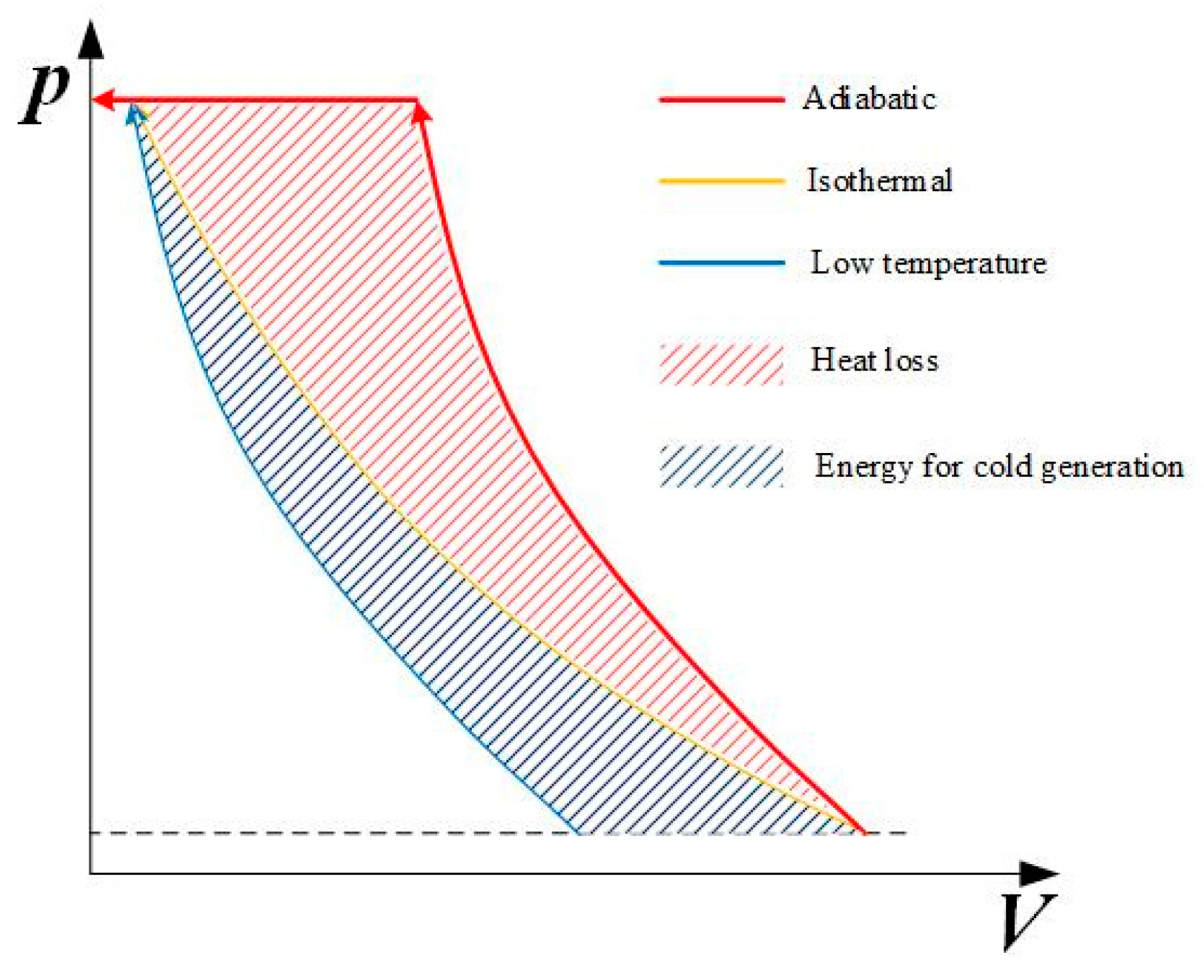
Air is compressed in the compressor. To save energy, air can be compressed by way of adiabatic, isothermal, and low temperature. As shown in
Figure 3, most compressors work under near adiabatic conditions, and the compression work consumption is the most. Though it could be stored as a form of heat, the cycle efficiency of compressors is limited by the poor heat transfer. To increase the compression efficiency, the heat of compression should be prevented, therefore, isothermal compression and low-temperature compression.
The isothermal approach is used to enhance the heat transfer of compressed air to maintain the temperature constant as the environment. Two main methods to achieve isothermal compression are to inject the liquid spray or foam into the compression chamber and liquid piston. For liquid spray injection, it can increase the heat transfer area because of the micro droplet area. This method was first proposed by Coney [
20]. By injecting the water spray into the compression chamber of a reciprocating compressor, the compression work can be reduced by 28% [
21]. Foam can also be injected into the compression chamber with a mixture of air and water [
22]. Injecting foam instead of water spray can lower the required energy for spray generation and can stay longer in the compression chamber. However, additional energy consumption is required to generate higher pressure (3~5 MPa) for micro droplets. Energy consumption of the micro spray droplets is equal to the work conservation when the water spray mass reaches 1.5 g/cycle (nozzle in diameter of 0.3 mm) [
23].
For a liquid piston, gas is compressed directly by a column of liquid in a chamber of fixed volume. It can be found that heat transfer is improved by using this proposed liquid piston compared with the conventional reciprocating piston through experimental investigation [
24,
25,
26]. The heat transfer area can be improved for adaption to a gas chamber with an irregular shape. Air leakage and friction resistance can also be lowered [
27]. However, the weakness is that air will be mixed with the liquid as the liquid piston is driven by the hydraulic system. Other problems such as noise, vibration, and intensive wear will also arise.
Low-temperature compression refers to lowering the air temperature at the inlet of the compressor by low-temperature refrigeration devices, which can reduce compression heat and energy consumption. Extra energy consumption is needed to make the cold source, which is the area enclosed by the blue line and yellow line in
Figure 3. Furthermore, low temperatures can cause frost, which can harm refrigeration devices.
This paper proposes a novel concept to achieve isothermal compression: isothermal piston. This can be applied in industrial compressors and refrigeration to increase the energy efficiency. Therefore, the energy consumption in fluid systems can be lowered significantly, and the dead volume can be compensated due to the mobility of the fluid.
3. Mathematical Model and Experimental Setup
Based on the conventional piston and combined with the porous heat transfer medium, the concept of an isothermal piston is proposed. Compression by an isothermal piston can enhance heat exchange, greatly reduce the air temperature in the compression chamber, and approach quasi-isothermal compression. At the same time, the introduction of porous media adds flow resistance to the piston and increases the complexity of the flow process.
The internal energy of the air is determined by the work done by the piston (
δW), the heat transferred to the system, and the enthalpy (
dHdis) transferred to the water. As there will be mass loss (discussed later), enthalpy should be introduced to describe the energy of air that dissolves into the water with compression. The compression process of air can be modeled by the state equation and energy equation as follows:
For the variation of the resistance pressure gradient caused by the relative displacement between the porous medium and the fluid, it can be determined by the Ergun surface cube model [
29,
30]. The change of resistance pressure gradient is mainly related to the structure of the porous medium, and is affected by the shape of pores. The pressure gradient
is shown by the following formula:
where
dL is on the opposite direction of the piston motion;
μ is the dynamic viscosity;
ρ is the density of fluids;
u is the relative velocity between a fluid and a porous medium;
K is the permeability of porous medium; and
Cc is the inertia coefficient of porous medium (or shape factor).
K and
C [
29,
30] are defined as:
where
a is a constant related to viscosity;
b is a constant related to inertia;
ε is the porosity; and
d is the hydraulic radius of a porous medium.
Substituting Equations (3) and (4) into Equation (2), the classical Ergun equation [
29,
30] is obtained as:
Air resistance is negligible as viscosity and density of air (17.9 × 10
−6 Pa∙s, 1.18 kg/m
3) is much smaller than that of water (1.01 × 10
−3 Pa∙s, 1 × 10
3 kg/m
3). The fluid resistance discussed in this paper was all about liquid resistance. Work done by the liquid resistance is:
where
l is the relative displacement of the porous medium and liquid. With the air pressure increasing as compression proceeds, there will be loss of air mass, which dissolves into the water. Henry’s law [
31] revealed the relation between the dissolved amount of air and the air pressure:
where
c (mol/L) is the molarity of gas dissolved into the liquid;
p is the gas pressure above the liquid at equilibrium conditions;
Hcp (mol/L∙atm) is Henry’s constant and is independent of temperature.
In order to measure the resistance between the porous medium and water during the operation of the isothermal piston, a tension pressure sensor is installed in the middle of the piston rod, and the resistance is obtained by the change of the data of the tension pressure sensor. The resistance measurement is shown in
Figure 6a.
An air cylinder is used to drive the isothermal piston. The supply pressure of the air source was set at 0.8 MPa, and a pressure regulator connected behind was used to stabilize the force applied to the isothermal piston. The moving direction of the piston was controlled by the solenoid valve. The system was operated for one cycle in this study, and the analysis is focused on the compression process. The specific experimental scheme is depicted in
Figure 6b [
32].
The system has good sealing performance in a static state. There will inevitably be leakage when the piston is moving. Compensation should be analyzed in this study. Experiments without a porous medium should be conducted compared with the simulation. As the system operates only one cycle, the compression process is nearly adiabatically. The pressure difference between the experiment and simulation was caused by air leakage. According to the state equation, the amount of gas leakage can be determined when the piston is in a different position. The leakage amount at each position of the piston can be estimated by Equation (8).
The compression system of the isothermal piston is shown in
Figure 6b. Parameters of the experimental setup are shown in
Table 2.
4. Results and Discussion
The effectiveness of the isothermal piston should be tested by experiments. Therefore, two experiments were conducted: an isothermal experiment (with isothermal piston) and adiabatic experiment (with conventional piston). The effectiveness of the isothermal piston can be verified intuitively through the p–V diagram. The air pressure will be lower if more heat is transferred. However, the pressure will also be lower due to the mass loss of compressed air. To verify the heat transfer effect of the isothermal piston, the pressure drop caused by the mass loss of air should be compensated, which is caused by dissolution and leakage in the compression process.
4.1. Compensation for Dissolution
The air will be dissolved into the water as the compression proceeds. Air mainly consists of O
2 (22%) and N
2 (78%), and Henry’s law constant is 1.3 × 10
−3 and 6.1 × 10
−4, respectively. Based on Equation (7), converting molarity to mass and water volume, the amount of dissolved air can be obtained as follows:
where
is the mass of dissolved air and
is the volume of water in the compression chamber. The dissolution rate of the isothermal experiment is shown in
Figure 7.
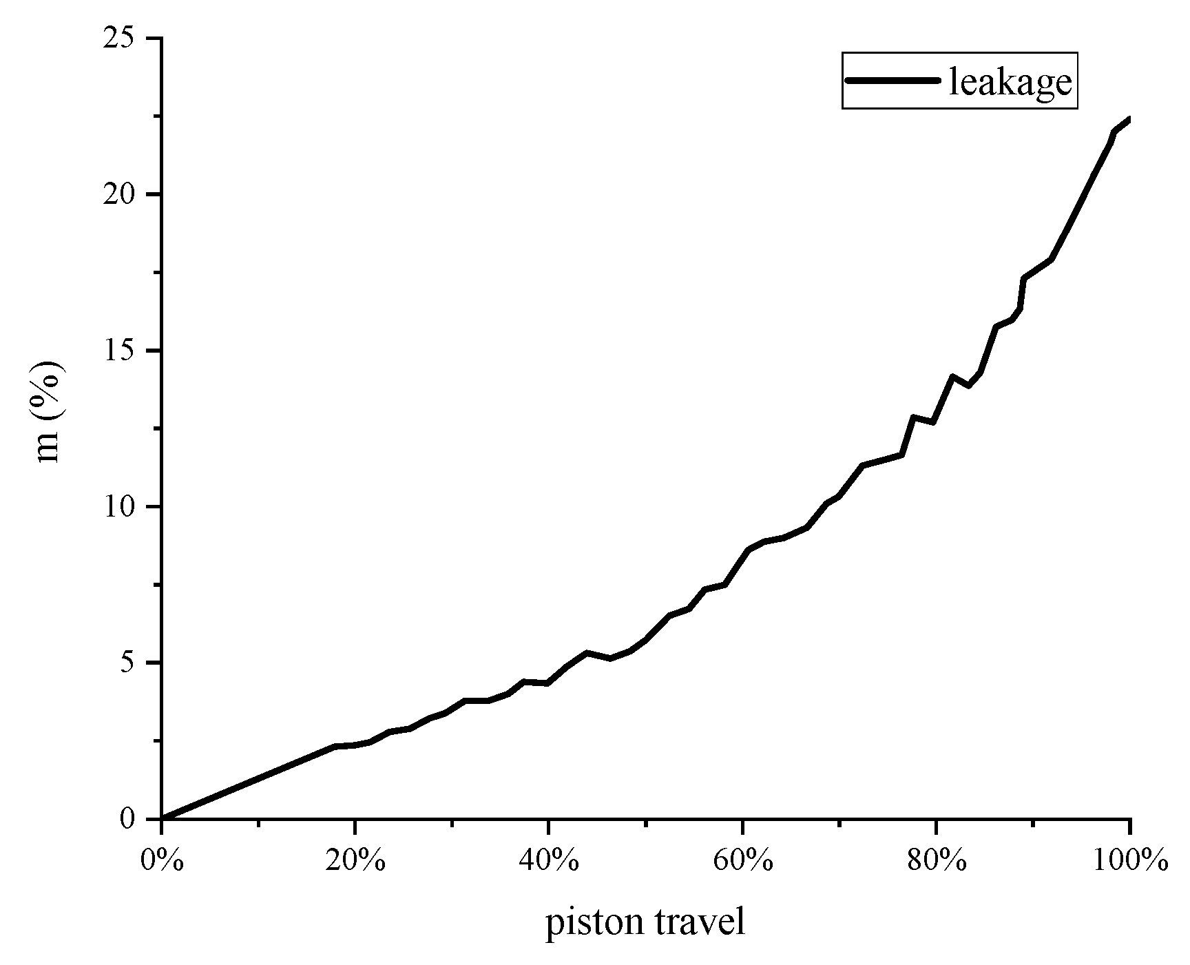
4.2. Compensation for Leakage
As the compression speed is so fast in one cycle, the heat transferred to the ambient can be ignored, so the adiabatic experiment can be treated as adiabatic compression, and
δQ is 0. Under this condition, the pressure drop between the experiment and simulation was caused by leakage, as shown in
Figure 8. The amount of air leakage can be estimated by Equation (10):
where
is the adiabatic pressure compensated by leakage. According to the state equation, energy equation and Henry’s law, it is obtained as follows:
The leakage rate of the two experiments were assumed to be the same by piston travel. The leakage rate of the isothermal experiment is shown in
Figure 9.
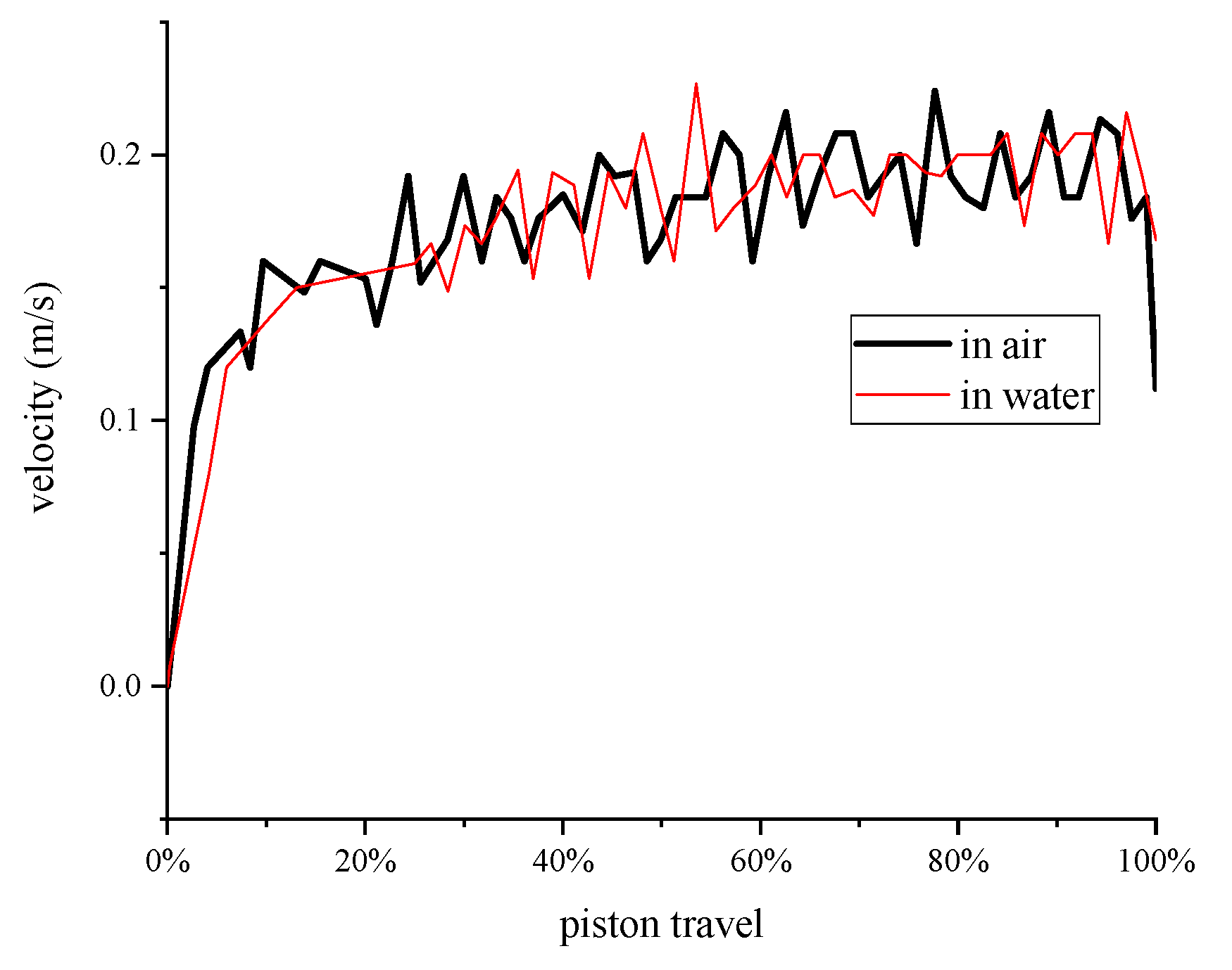
4.3. Friction Analysis
The air flow was set the same for the two contrast experiments in order to make the speed of the piston the same. The piston speed was 0.2 m/s, as shown in
Figure 10. The piston speed of the two experiments agreed well.
The resistance measured by the experiment and the results calculated by the model are shown in
Figure 11. There were some fluctuations in the measured resistance value, but the overall resistance value was around 2.5 N, and the measured values were all smaller than the calculated value of the model. The reason may be that the model is an empirical model, which is different from the actual working condition, thus it can be used as a reference.
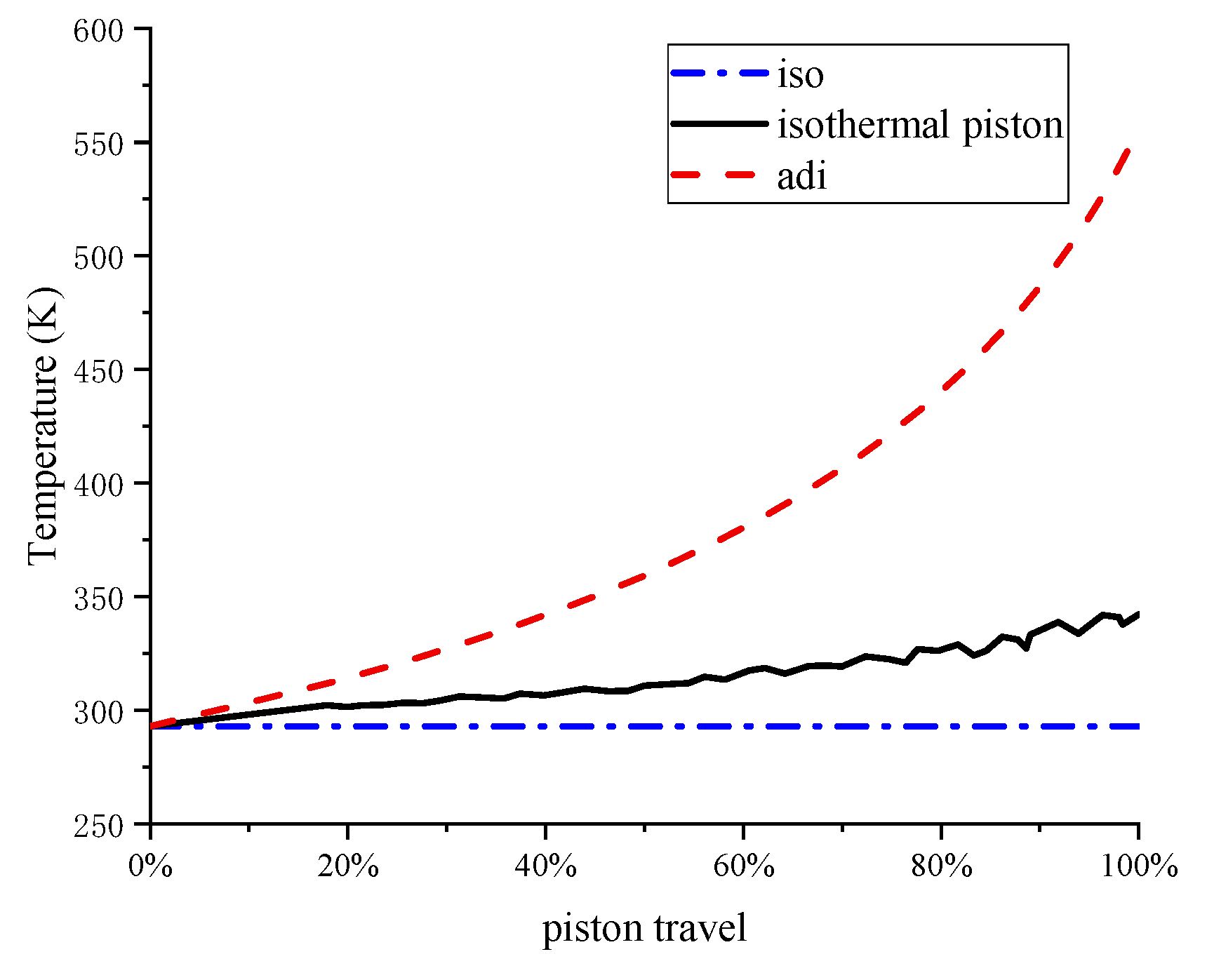
4.4. Validation of Effectiveness
The mass of the remaining air in the chamber can be acquired as:
where
m0 is the initial mass of air. The measurement of transient temperature is challenging while compressing, as the response time of temperature sensors cannot be in the order of milliseconds. From the pressure, volume, and mass of the air, the temperature in the isothermal experiment can be calculated based on the ideal gas law as follows, which is shown in
Figure 12.
The pressure drop caused by dissolution and leakage is
and
, respectively, which are expressed as:
The air pressure of the isothermal experiment compensated by dissolution and leakage
is:
The air pressure is shown in
Figure 13, which increased from atmospheric pressure to the compression ratio, at which point the air is pumped at a constant pressure out of the chamber. Note that due to the good heat transfer of the isothermal piston, the air pressure is lower, and the pressure in the isothermal piston chamber rises far slower than the conventional piston chamber.
The work required to compress the air can be computed by numerically integrating the product of the change of volume times the difference of the air pressure minus the atmospheric pressure.
The compression work, as seen in
Figure 14, was lower than the adiabatic compression due to the enhancement of heat transfer. Considering the frictional work, the total work done on the system is also presented. The effect of frictional forces on total work was relatively small.
4.5. Discussion
The isothermal piston illustrates a significant improvement in gas compression efficiency by using an isothermal piston in place of a conventional one. From this study, the isothermal piston chamber required 45% less work than the conventional piston chamber. The improvement was the result of removing more heat during the compression process, thus lowering the work required to compress the gas. Compressed air is stored in a pressure vessel before use, and will cool to near ambient temperature during storage. Therefore, any heat energy added to the gas during compression is lost. From this point, conducting a near-isothermal compression with an isothermal piston requires less work to compress the gas to the same final pressure than a near-adiabatic compression.
Near-isothermal compression is accomplished in the isothermal piston chamber by maximizing the heat transfer area via the structure of a porous medium. The porous medium has a large specific surface area and porosity, which provides a larger heat transfer area. As copper is a good conductor of heat, the compression heat can be rapidly conducted away. Unfortunately, resistance of frictional forces can be increased as the porous medium proceeds in the liquid.
The work to overcome frictional forces is negligible on such conditions of the experiments, but the influence cannot be neglected for the investigation of an isothermal piston. When the operation speed is relatively high, the resistance will increase significantly.
It does need to be clearly stated that this paper made assumptions to simplify the analysis and illustrate the isothermal piston concept. The temperature will be affected by dissolution and leakage. However, the effect is slight because the rate of mass loss is negligible compared to the remaining mass of air. When compensating, the effect of mass loss of air on temperature is ignored. The air temperature in an adiabatic experiment is assumed as the same as the simulation, and is regarded to have no effect on the dissolution and leakage when calculating the air temperature.
Near-isothermal compression with good heat transfer makes the isothermal piston concept advantageous in many applications. While this paper focused on a single application of an air compressor, this concept can also be used for condensing. The working medium can be the cooling liquid for the isothermal piston.
5. Conclusions
In the energy consumption distribution of a fluid power system, energy loss of pneumatic systems account for a fairly large portion. The energy loss of pneumatic systems is mainly in the pipelines and compressors. The energy loss in pipelines is mainly caused by leakage and pressure loss, while in compressors, the energy loss is mainly from the heat loss in the compression of a gas. Based on this, this paper proposed an isothermal compression method using an isothermal piston. Considering the influence of gas leakage and dissolution, the effectiveness was validated.
Isothermal piston compression is an exciting concept that can significantly lower the energy consumption of gas compression. This concept was demonstrated to lower the total energy consumption by 45% at the pressure ratio of 4:1. The air temperature was lowered from 517 K to 342 K. The effect of frictional forces was negligible (0.21% of the compression work) at the speed of 100 rpm.
The isothermal piston concept relies on maximizing the heat transfer area via the porous medium, allowing the rapid heat transfer from a gas to a liquid.
While the total energy consumption can be lowered with an isothermal piston, it operates at a relatively low speed compared with the actual conditions of a compressor. How frictional forces will affect the total energy consumption at high speed should be investigated. Further future work also includes the optimum design of an isothermal piston and an exploration of its applications.


