Performance Optimization of a Condenser in Ocean Thermal Energy Conversion (OTEC) System Based on Constructal Theory and a Multi-Objective Genetic Algorithm


Abstract
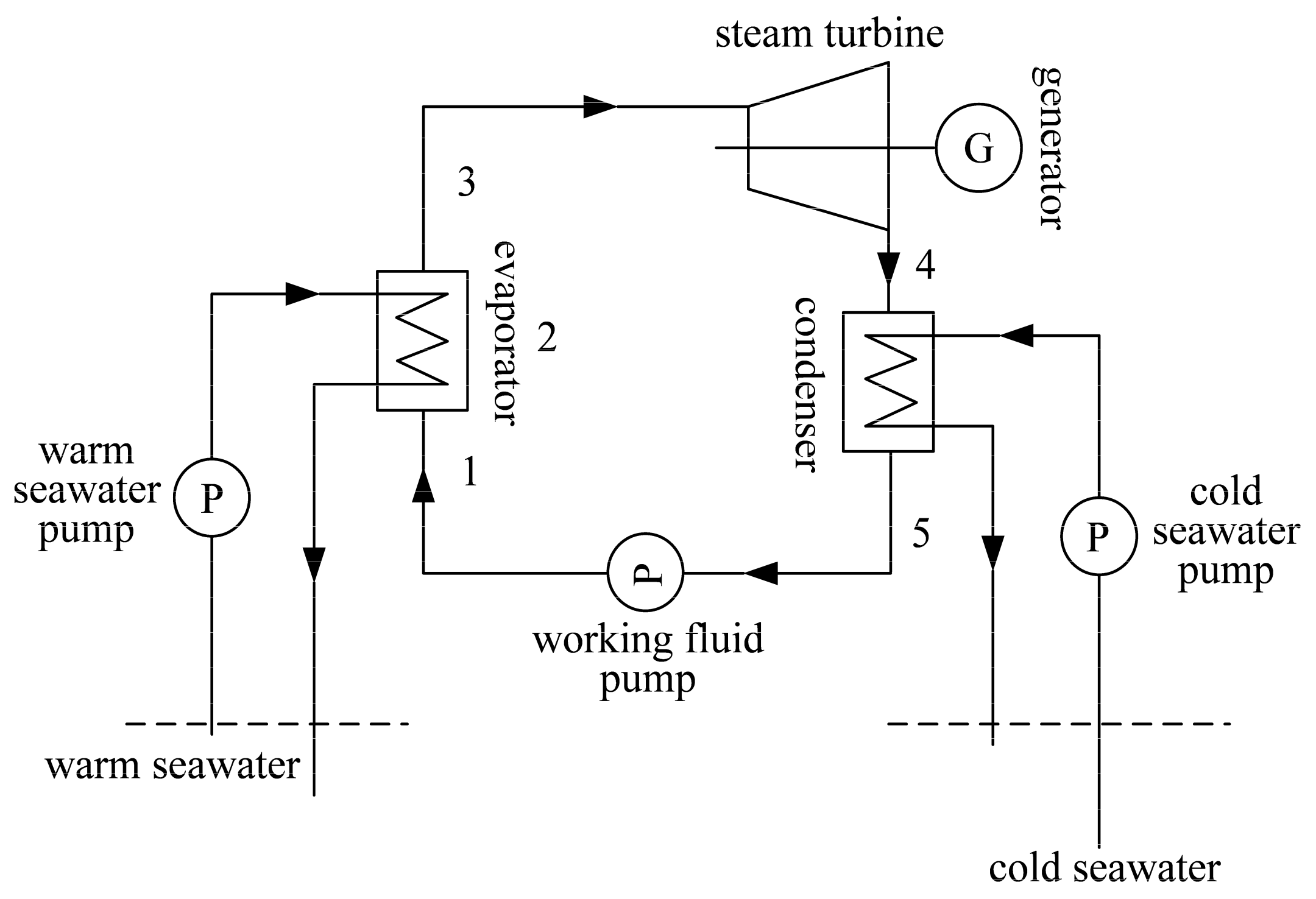
1. Introduction
2. Plate Condenser and Its Performance
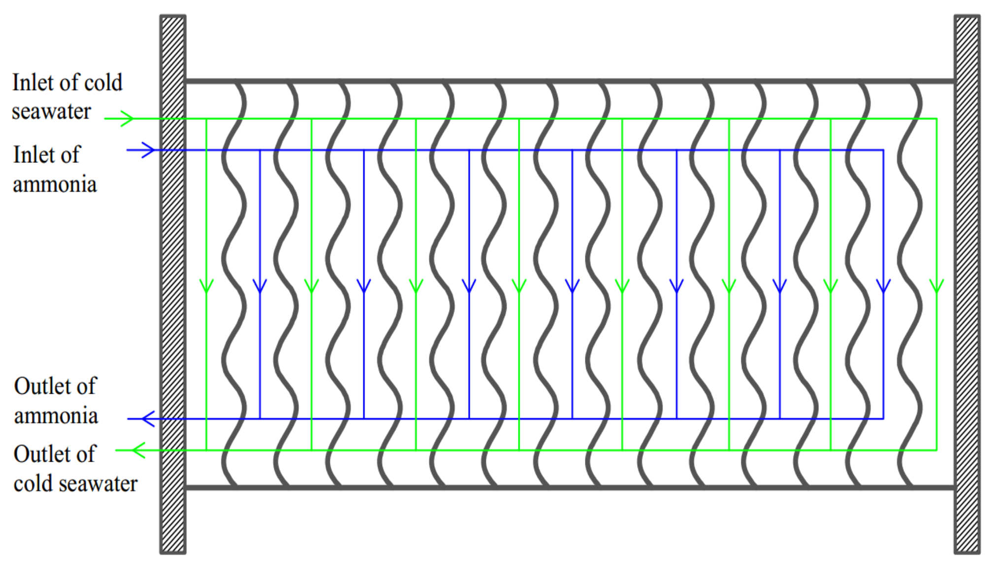
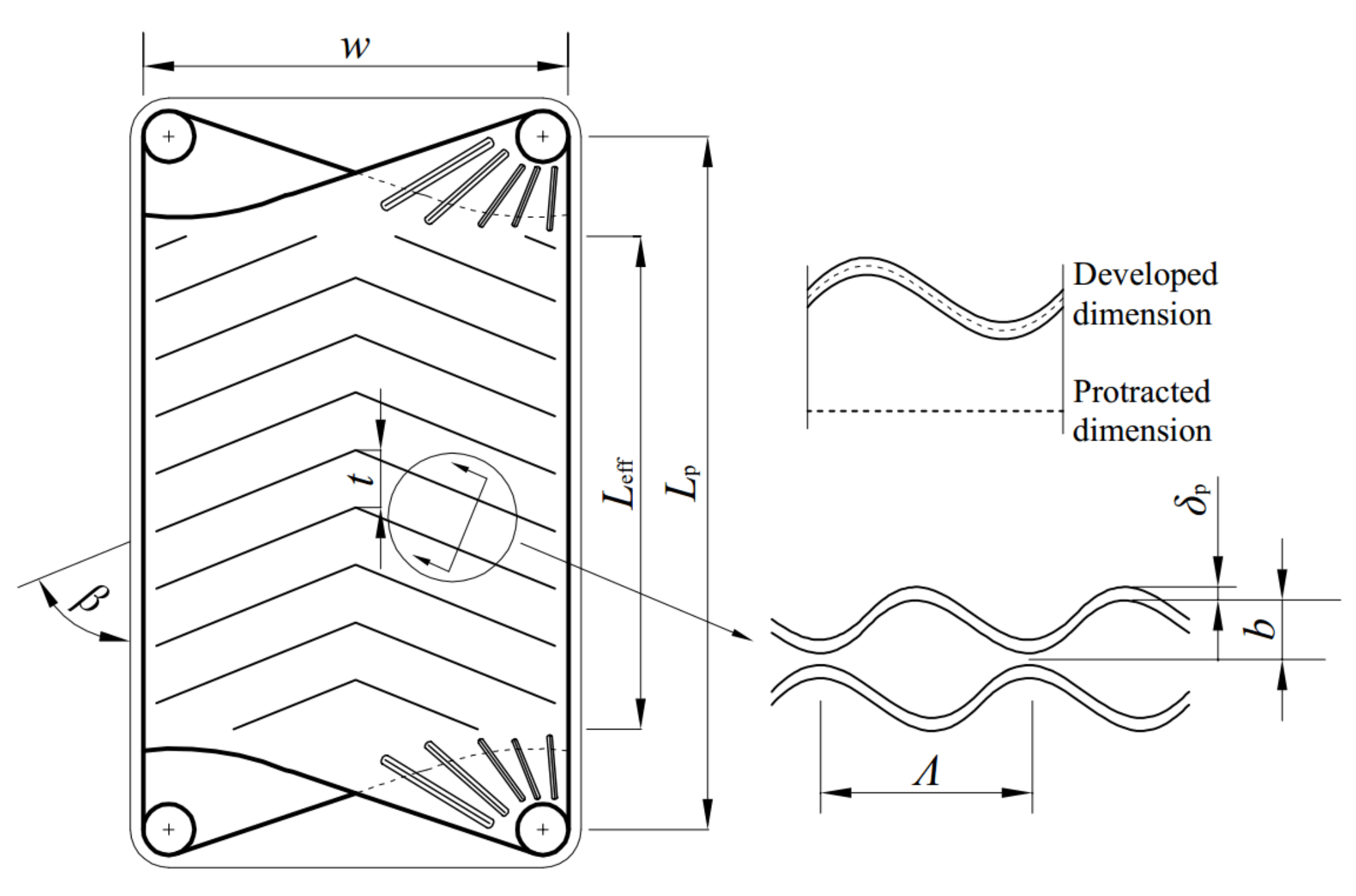
2.1. Structure of Plate Condenser
2.2. Assumptions of Model
- (1)
- The flow in the plate condenser is a stable state and homogeneous for flow direction.
- (2)
- The working fluid is a two-phase state at the inlet of the plate condenser.
- (3)
- Considering that the cold seawater is enough, the working fluid will be cooled to a saturated liquid state (SLS).
- (4)
- The pressure drops at the manifolds and ports are ignored because only the HTP structure is studied in this paper. The influences of the manifolds and ports on the pressure drops and overall performance of OTEC system will be studied in future work.
2.3. Performance of Plate Condenser on Working Fluid Side
2.4. Performance of Plate Condenser on Cold Seawater Side
2.5. Overall Performance of Plate Condenser
3. Constructal Design for Plate Condenser with Conventional Optimization Method
3.1. Optimization Objective of Constructal Design
3.2. Optimization Procedure of Constructal Design
- (1)
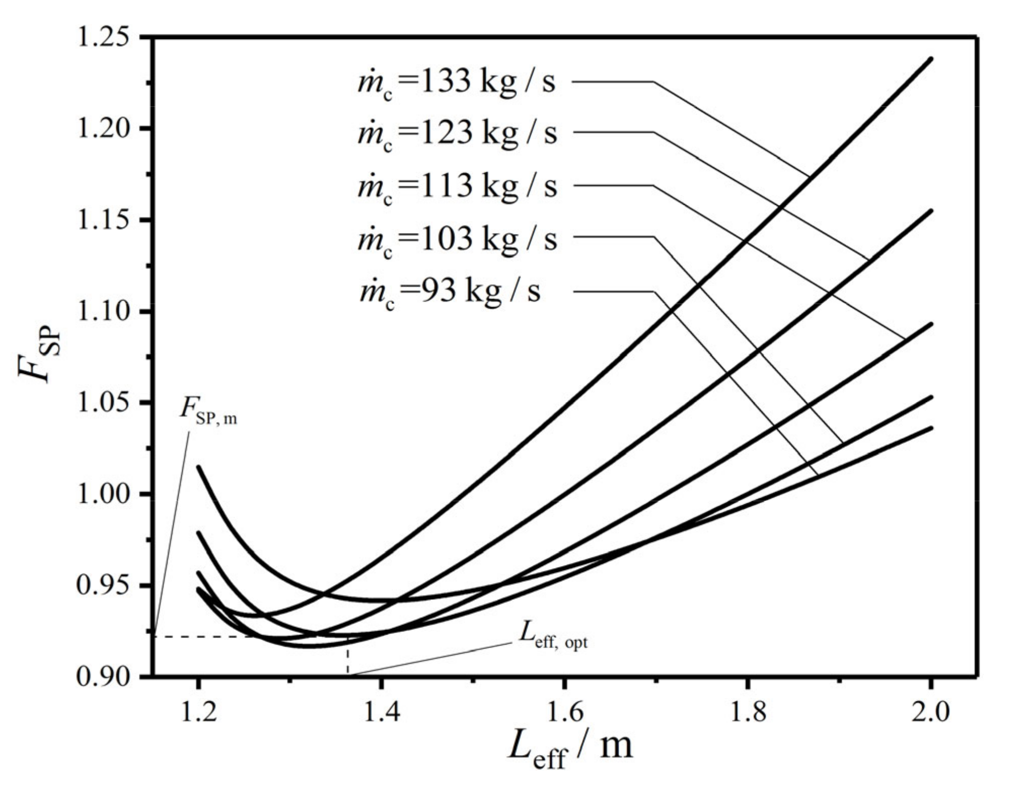
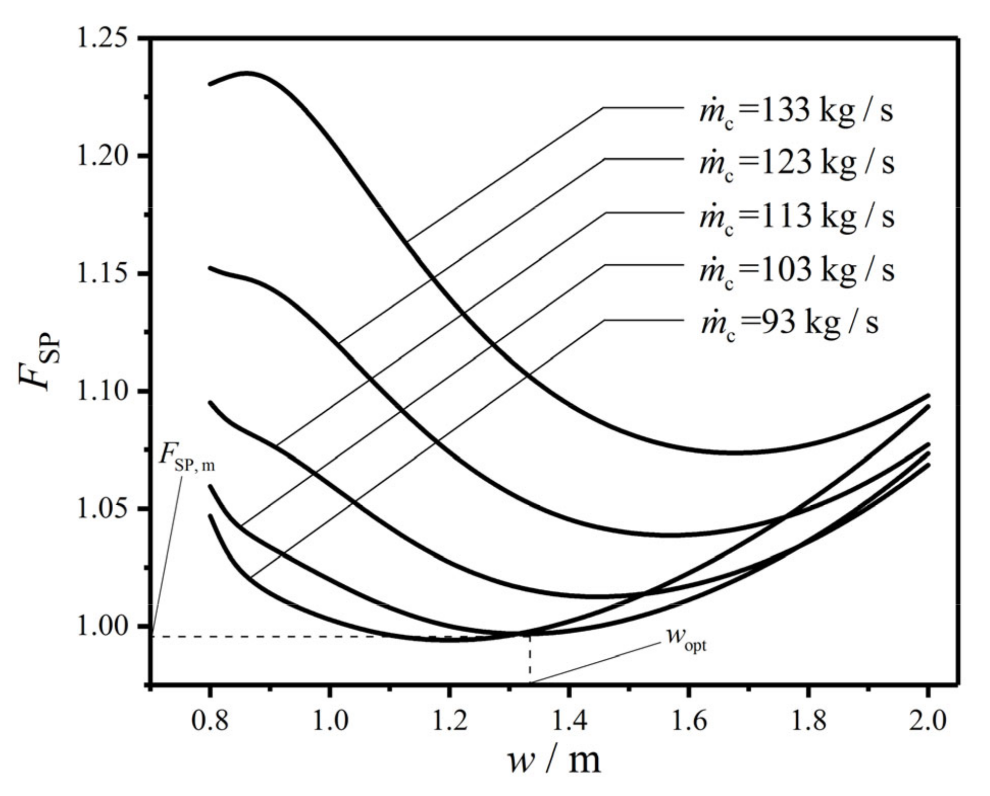
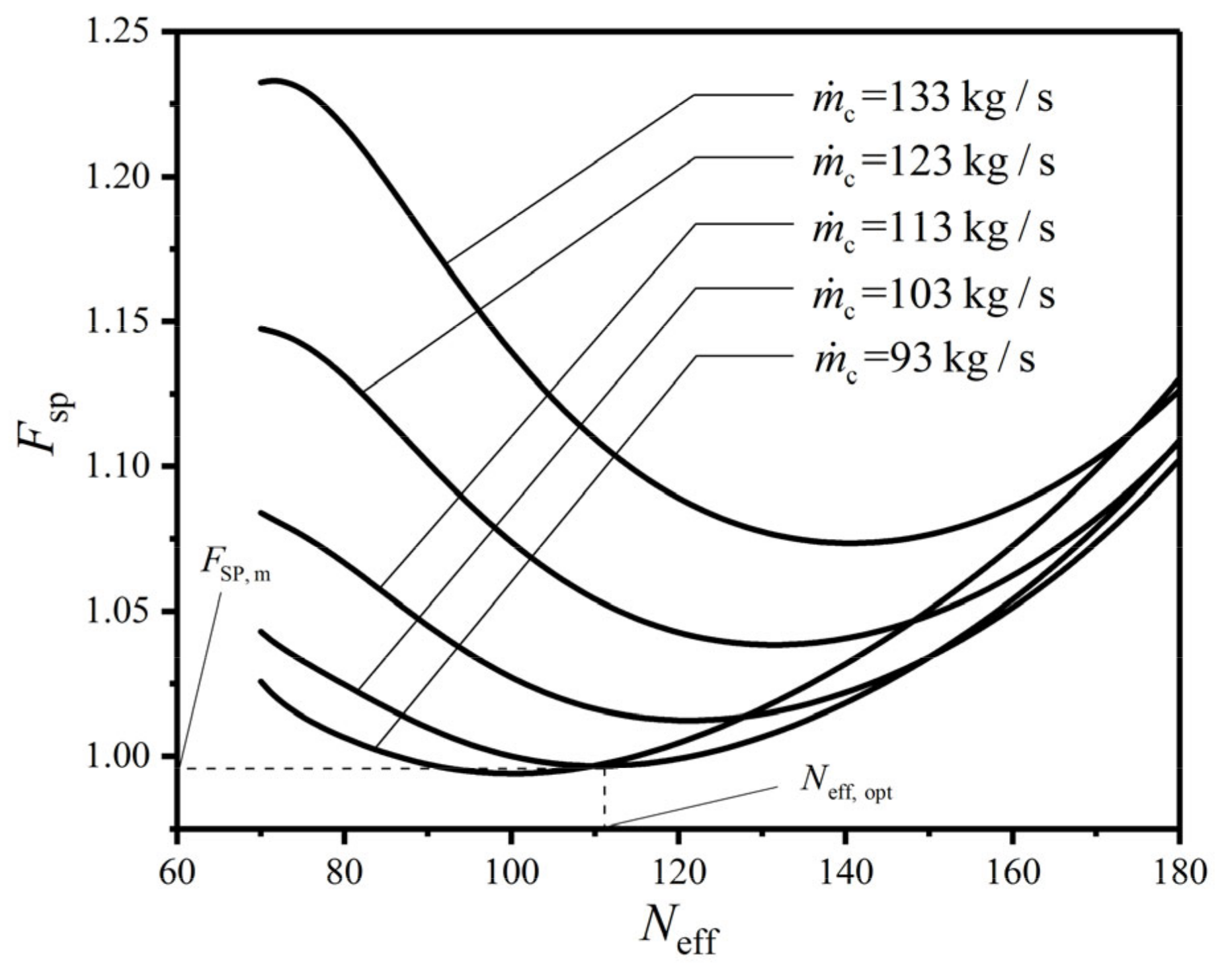
- The single variable optimization is carried out. The relationship between the CF () and HTP effective length () is obtained with the given HTP width () and effective number (). The relationships between and as well as between and are obtained by applying a similar method.
- (2)
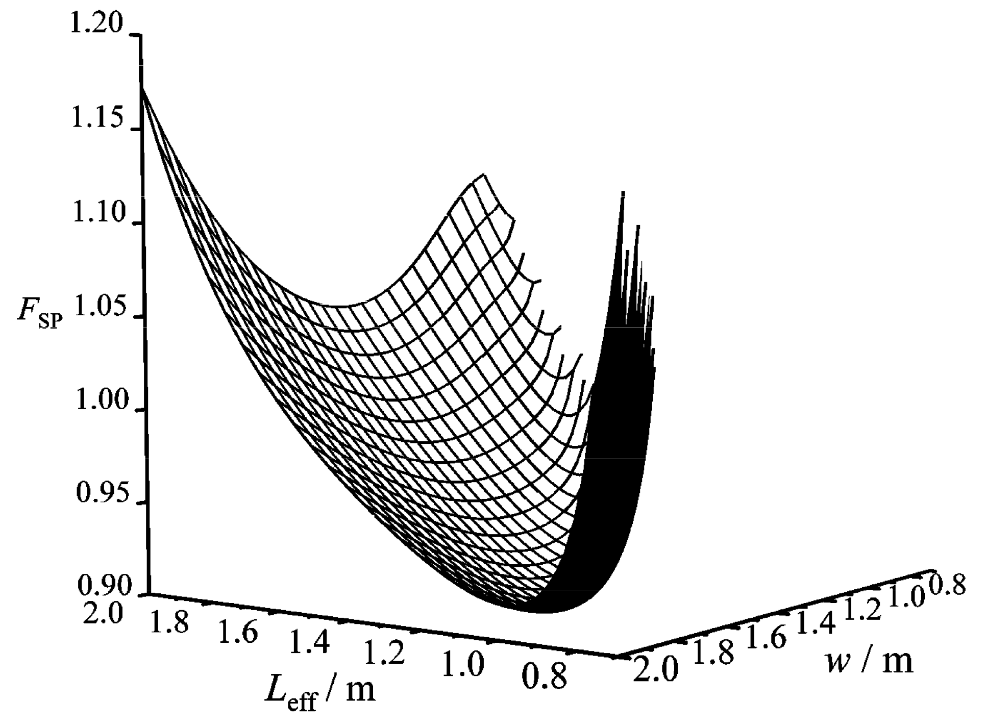
- The double variable optimization is carried out by releasing the constraint of on the basis of singly optimizing . The relationships among , , and are obtained with the given .
- (3)
- The three variable optimization is carried out by releasing constraint of on the basis of step 2. The relationships among , , , and are obtained.
- (4)
- On the basis of step 3, the CORs of the plate condenser with different structural parameters and weighting coefficient are obtained. The subscripts “m” and “mm” mean the primary and twice minimizations, respectively, and the subscripts “opt” and “oo” mean the primary and twice optimizations, respectively.
3.3. Results of Constructal Designs
3.3.1. Single Variable Optimization
3.3.2. Double Variable Optimization
3.3.3. Three Variable Optimization
3.3.4. Effects of Design Parameters on Optimization Results
4. Constructal Design for Plate Condenser with Multi-Objective Genetic Algorithm
4.1. Optimization Procedure of Multi-Objective Genetic Algorithm
- (1)
- An initial population with scale is randomly generated, and the first offspring population is obtained through selection, crossover, and variation after non-dominated sorting.
- (2)
- The parent and offspring populations start to merge from the second generation. At the same time of performing the fast non-dominated sorting, the crowded distance of each individual in the non-dominated layer is calculated. A new parent population is formed by selecting suitable individuals based on the non-dominated relationship and the crowded distance of the individual.
- (3)
- A new offspring population is generated through selection, crossover, and variation of the parent population, and to circulate repeatedly until the ending conditions are satisfied. In this paper, the size of the population is set as 300, the evolution generation is set as 500, and “PlotFcns” is chosen as “gaplotpareto”.
4.2. Results of Constructal Design
5. Conclusions
- (1)
- There is a primary optimal HTP effective length (), a primary optimal HTP width (), and a primary optimal HTP effective number () to make respectively reach 0.922, 0.997, and 0.997. has a more significant effect than and , and it can be chosen as the main design parameter to improve the performance of the plate condenser.
- (2)
- Continuing to optimize on the basis of singly optimizing can partly improve the comprehensive performance of the plate condenser. The twice minimum CF () after simultaneously optimizing and is 0.901, which is 2.3% less than after singly optimizing . The twice optimal HTP effective length () and are and , respectively.
- (3)
- Further optimizing the HTP effective number () on the basis of twice optimization cannot significantly improve the comprehensive performance of the plate condenser. The corrugation angle (), corrugation wavelength (), effective volume (), and weighting coefficient () have different influences on the optimal performance and optimal construct. gradually augments with the increases of , , and , and gradually diminishes with the increase of .
- (4)
- Pareto optimal set can provide better choices for the performance optimizations of the plate condenser.
- (5)
- and are two important parameters of the plate condenser. Single, double, and three variable optimizations, as well as the Pareto optimal set, all provide the optimal design values of the plate condenser, and they can be an important basis and criteria for designers to design the plate condensers.
Author Contributions
Funding
Acknowledgments
Conflicts of Interest
Nomenclature
| heat transfer area, | |
| heat transfer area of single heat transfer plate, | |
| projected area, | |
| cross-sectional area of single flow channel, | |
| plate spacing between two adjacent plates, | |
| specific heat at constant pressure, | |
| hydraulic diameter, | |
| composite function | |
| friction factor | |
| mass flow rate per cross-sectional area, | |
| enthalpy, | |
| total heat transfer coefficient, | |
| length, | |
| mass, | |
| number of heat transfer plates or flow channels | |
| Nusselt number | |
| quantity of condensation sections | |
| pumping power, | |
| pressure, | |
| Prandtl number | |
| quantity of heat transfer, | |
| fouling resistance, | |
| Reynolds number | |
| entropy generation, | |
| temperature, | |
| corrugation pitch, | |
| volume, | |
| width, | |
| dimensionless corrugation parameter of heat transfer plate | |
| vapor quality | |
| Greek letters | |
| surface heat transfer coefficient, | |
| corrugation angle, | |
| thickness, | |
| surface enlargement factor of heat transfer plate | |
| pump efficiency | |
| thermal conductivity, | |
| density, | |
| dynamic viscosity, | |
| corrugation wavelength, | |
| logarithmic mean temperature difference, | |
| pressure drop, | |
| Subscripts | |
| ave | average value |
| c | cold seawater |
| cond | condenser |
| eq | equivalent value |
| eff | effective value |
| sequence number of each small condensation section | |
| in | inlet |
| int | initial value |
| ios | isolated system |
| l | saturated liquid state |
| m | primary minimum value |
| mm | twice minimum value |
| opt | primary optimal value |
| oo | twice optimal value |
| out | outlet |
| p | heat transfer plate |
| sum | total |
| v | saturated vapor state |
| wf | working fluid |
| cyclic state points | |
| Superscript | |
| rate, | |
| CF | composite function |
| COR | constructal optimization result |
| EGR | entropy generation rate |
| HE | heat exchanger |
| HRSG | heat recovery steam generator |
| HTC | heat transfer coefficient |
| HTP | heat transfer plate |
| HTR | heat transfer rate |
| MFR | mass flow rate |
| OTEC | ocean thermal energy conversion |
| SLS | saturated liquid state |
References
- D’Arsonval, A. Utilisation des forces naturelles, avenir de l’électricité. Rev. Sci. 1881, 17, 370–372. [Google Scholar]
- Claude, G. Power from the tropical seas. Mech. Eng. 1930, 52, 1039–1044. [Google Scholar]
- Lennard, D. Ocean thermal energy conversion—Past progress and future prospects. IEEE Proc. A Phys. Sci. Meas. Instrum. Manag. Educ. Rev. 1987, 134, 381. [Google Scholar] [CrossRef]
- Yeh, R.-H.; Su, T.-Z.; Yang, M.-S. Maximum output of an OTEC power plant. Ocean Eng. 2005, 32, 685–700. [Google Scholar] [CrossRef]
- Semmari, H.; Stitou, D.; Mauran, S. A novel Carnot-based cycle for ocean thermal energy conversion. Energy 2012, 43, 361–375. [Google Scholar] [CrossRef]
- Ikegami, Y.; Yasunaga, T.; Morisaki, T. Ocean Thermal Energy Conversion Using Double-Stage Rankine Cycle. J. Mar. Sci. Eng. 2018, 6, 21. [Google Scholar] [CrossRef]
- Wu, Z.X.; Feng, H.J.; Chen, L.G.; Xie, Z.J.; Cai, C.G.; Xia, S.J. Optimal design of dual-pressure turbine in OTEC system based on constructal theory. Energy Convers. Manag. 2019, 201, 112179. [Google Scholar] [CrossRef]
- Wu, Z.X.; Feng, H.J.; Chen, L.G.; Tang, W.; Shi, J.C.; Ge, Y.L. Constructal thermodynamic optimization for ocean thermal energy conversion system with dual-pressure organic Rankine cycle. Energy Convers. Manag. 2020, 210, 112727. [Google Scholar] [CrossRef]
- Yasunaga, T.; Ikegami, Y. Finite-Time Thermodynamic Model for Evaluating Heat Engines in Ocean Thermal Energy Conversion. Entropy 2020, 22, 211. [Google Scholar] [CrossRef]
- Uehara, H.; Kusuda, H.; Monde, M.; Nakaoka, T.; Sumitomo, H. Shell-and-Plate-Type Heat Exchangers for OTEC Plants. J. Sol. Energy Eng. 1984, 106, 286–290. [Google Scholar] [CrossRef]
- Uehara, H.; Ikegami, Y. Optimization of a Closed-Cycle OTEC System. J. Sol. Energy Eng. 1990, 112, 247–256. [Google Scholar] [CrossRef]
- Chen, B.H.; Li, X.R. Technical Application Manual for Plate Heat Exchanger and Heat Exchanger Device; China Architecture & Building Press: Beijing, China, 2005. (In Chinese) [Google Scholar]
- Yamada, N.; Hoshi, A.; Ikegami, Y. Performance simulation of solar-boosted ocean thermal energy conversion plant. Renew. Energy 2009, 34, 1752–1758. [Google Scholar] [CrossRef]
- Wang, M.; Jing, R.; Zhang, H.; Meng, C.; Li, N.; Zhao, Y. An innovative Organic Rankine Cycle (ORC) based Ocean Thermal Energy Conversion (OTEC) system with performance simulation and multi-objective optimization. Appl. Therm. Eng. 2018, 145, 743–754. [Google Scholar] [CrossRef]
- Bernardoni, C.; Manzolini, G.; Giostri, A. Techno-economic analysis of closed OTEC cycles for power generation. Renew. Energy 2019, 132, 1018–1033. [Google Scholar] [CrossRef]
- Fontaine, K.; Yasunaga, T.; Ikegami, Y. OTEC Maximum Net Power Output Using Carnot Cycle and Application to Simplify Heat Exchanger Selection. Entropy 2019, 21, 1143. [Google Scholar] [CrossRef]
- Nakaoka, T.; Uehara, H. Performance test of a shell-and-plate-type condenser for OTEC. Exp. Therm. Fluid Sci. 1988, 1, 275–281. [Google Scholar] [CrossRef]
- Yan, Y.-Y.; Lio, H.-C.; Lin, T.-F. Condensation heat transfer and pressure drop of refrigerant R-134a in a plate heat exchanger. Int. J. Heat Mass Transf. 1999, 42, 993–1006. [Google Scholar] [CrossRef]
- Wang, L.K.; Sunden, B.; Yang, Q.S. Pressure Drop Analysis of Steam Condensation in a Plate Heat Exchanger. Heat Transf. Eng. 1999, 20, 71–77. [Google Scholar] [CrossRef]
- Han, D.H.; Lee, K.J.; Kim, Y.H. The characteristics of condensation in brazed plate heat exchangers with different chevron angles. J. Korean Phys. Soc. 2003, 43, 66–73. [Google Scholar]
- García-Cascales, J.R.; García, F.V.; Corberan, J.M.; Maciá, J.G. Assessment of boiling and condensation heat transfer correlations in the modelling of plate heat exchangers. Int. J. Refrig. 2007, 30, 1029–1041. [Google Scholar] [CrossRef]
- Longo, G.A.; Zilio, C.; Righetti, G.; Brown, J.S. Condensation of the low GWP refrigerant HFO1234ze(E) inside a Brazed Plate Heat Exchanger. Int. J. Refrig. 2014, 38, 250–259. [Google Scholar] [CrossRef]
- Longo, G.A.; Righetti, G.; Zilio, C. A new computational procedure for refrigerant condensation inside herringbone-type Brazed Plate Heat Exchangers. Int. J. Heat Mass Transf. 2015, 82, 530–536. [Google Scholar] [CrossRef]
- Eldeeb, R.; Aute, V.; Radermacher, R. A survey of correlations for heat transfer and pressure drop for evaporation and condensation in plate heat exchangers. Int. J. Refrig. 2016, 65, 12–26. [Google Scholar] [CrossRef]
- Shon, B.H.; Jeon, S.W.; Kim, Y.; Kang, Y.T. Review: Condensation and Evaporation Characteristics of Low GWP Refrigerants in Plate Heat Exchangers. Int. J. Air-Conditioning Refrig. 2016, 24, 1630004. [Google Scholar] [CrossRef]
- Shon, B.H.; Jung, C.W.; Kwon, O.J.; Choi, C.K.; Kang, Y.T. Characteristics on condensation heat transfer and pressure drop for a low GWP refrigerant in brazed plate heat exchanger. Int. J. Heat Mass Transf. 2018, 122, 1272–1282. [Google Scholar] [CrossRef]
- Bejan, A. Street network theory of organization in nature. J. Adv. Transp. 1996, 30, 85–107. [Google Scholar] [CrossRef]
- Bejan, A. Constructal-theory network of conducting paths for cooling a heat generating volume. Int. J. Heat Mass Transf. 1997, 40, 799–816. [Google Scholar] [CrossRef]
- Bejan, A. Shape and Structure, from Engineering to Nature; Cambridge University Press: Cambridge, UK, 2000. [Google Scholar]
- Kim, S.; Lorente, S.; Bejan, A. Design with Constructal Theory: Vascularized Composites for Volumetric Cooling; Wiley: Hoboken, NJ, USA, 2008; pp. 437–444. [Google Scholar]
- Chen, L.G. Progress in study on constructal theory and its applications. Sci. China Ser. E Technol. Sci. 2012, 55, 802–820. [Google Scholar] [CrossRef]
- Bejan, A. Constructal Law: Optimization as Design Evolution. J. Heat Transf. 2015, 137, 061003. [Google Scholar] [CrossRef]
- Chen, L.G.; Feng, H.J.; Xie, Z.H. Multi-Objective Constructal Optimizations for Fluid Flow, Heat and Mass Transfer Processes; Science Press: Beijing, China, 2016. (In Chinese) [Google Scholar]
- Chen, L.G.; Feng, H.J.; Xie, Z.H. Generalized Thermodynamic Optimization for Iron and Steel Production Processes: Theoretical Exploration and Application Cases. Entropy 2016, 18, 353. [Google Scholar] [CrossRef]
- Feng, H.J.; Chen, L.G.; Xie, Z.H. Multi-disciplinary, multi-objective and multi-scale constructal optimizations for heat and mass transfer processes performed in Naval University of Engineering, a review. Int. J. Heat Mass Transf. 2017, 115, 86–98. [Google Scholar] [CrossRef]
- Miguel, A.F.; Rocha, L.A.O. Tree-Shaped Fluid Flow and Heat Transfer; Springer: Berlin/Heidelberg, Germany, 2018. [Google Scholar]
- Chen, L.G.; Xiao, Q.H.; Feng, H.J. Constructal Optimizations for Heat and Mass Transfers Based on the Entransy Dissipation Extremum Principle, Performed at the Naval University of Engineering: A Review. Entropy 2018, 20, 74. [Google Scholar] [CrossRef]
- Bejan, A. Constructal law, twenty years after. Proc. Rom. Acad. Ser. A Math. Phys. Tech. Sci. Inform. Sci. 2018, 18, 309–311. [Google Scholar]
- Rocha, L.A.O.; Lorente, S.; Bejan, A. Constructal Theory in Heat Transfer. Handb. Therm. Sci. Eng. 2018, 329–360. [Google Scholar] [CrossRef]
- You, J.; Feng, H.J.; Chen, L.G.; Xie, Z.H. Constructal optimization for cooling a nonuniform heat generating disc-shaped area by conduction. Entropy 2018, 20, 685. [Google Scholar] [CrossRef]
- Chen, L.G.; Feng, H.J.; Xie, Z.H.; Sun, F.R. Progress of constructal theory in China over the past decade. Int. J. Heat Mass Transf. 2019, 130, 393–419. [Google Scholar] [CrossRef]
- Lorente, S.; Bejan, A. Current trends in constructal law and evolutionary design. Heat Transfer-Asian Res. 2019, 48, 3574–3589. [Google Scholar] [CrossRef]
- Bejan, A. Freedom and Evolution: Hierarchy in Nature, Society and Science; Springer: Cham, Switzerland, 2020. [Google Scholar]
- Chen, L.G.; Yang, A.B.; Feng, H.J.; Ge, Y.L.; Xia, S.J. Constructal design progress for eight types of heat sinks. Sci. China Ser. E Technol. Sci. 2020, 63, 879–911. [Google Scholar] [CrossRef]
- Bejan, A.; Gunes, U.; Sahin, B. University Rankings: Quality, Size and Permanence. Eur. Rev. 2020, 1–22. [Google Scholar] [CrossRef]
- Zhang, F.Y.; Feng, H.J.; Chen, L.G.; You, J.; Xie, Z.J. Constructal Design of an Arrow-Shaped High Thermal Conductivity Channel in a Square Heat Generation Body. Entropy 2020, 22, 475. [Google Scholar] [CrossRef]
- Wang, R.; Xie, Z.H.; Yin, Y.; Chen, L.G. Constructal design of elliptical cylinders with heat generating for entropy generation minimization. Entropy 2020, 22, 651. [Google Scholar] [CrossRef]
- Vargas, J.; Bejan, A. Thermodynamic optimization of finned crossflow heat exchangers for aircraft environmental control systems. Int. J. Heat Fluid Flow 2001, 22, 657–665. [Google Scholar] [CrossRef]
- Bejan, A. Dendritic constructal heat exchanger with small-scale crossflows and larger-scales counterflows. Int. J. Heat Mass Transf. 2002, 45, 4607–4620. [Google Scholar] [CrossRef]
- Sotoodeh, A.F.; Amidpour, M.; Ghazi, M. Developing of constructal theory concept for plate fin heat exchanger modeling, design and optimization. Int. J. Exergy 2015, 18, 22–45. [Google Scholar] [CrossRef]
- Xie, G.; Song, Y.; Asadi, M.; Lorenzini, G. Optimization of Pin-Fins for a Heat Exchanger by Entropy Generation Minimization and Constructal Law. J. Heat Transf. 2015, 137, 061901. [Google Scholar] [CrossRef]
- Bejan, A.; Alalaimi, M.; Sabau, A.; Lorente, S. Entrance-length dendritic plate heat exchangers. Int. J. Heat Mass Transf. 2017, 114, 1350–1356. [Google Scholar] [CrossRef]
- Bejan, A.; Lorente, S.; Martins, L.; Meyer, J.P. The constructal size of a heat exchanger. J. Appl. Phys. 2017, 122, 064902. [Google Scholar] [CrossRef]
- Feng, H.J.; Chen, L.G.; Xia, S.J. Constructal design for disc-shaped heat exchanger with maximum thermal efficiency. Int. J. Heat Mass Transf. 2019, 130, 740–746. [Google Scholar] [CrossRef]
- Feng, H.J.; Chen, L.G.; Wu, Z.X.; Xie, Z.J. Constructal design of a shell-and-tube heat exchanger for organic fluid evaporation process. Int. J. Heat Mass Transf. 2019, 131, 750–756. [Google Scholar] [CrossRef]
- Cai, C.G.; Feng, H.J.; Chen, L.G.; Wu, Z.X.; Xie, Z.J. Constructal design of a shell-and-tube evaporator with ammonia-water working fluid. Int. J. Heat Mass Transf. 2019, 135, 541–547. [Google Scholar] [CrossRef]
- Wu, Z.X.; Feng, H.J.; Chen, L.G.; Xie, Z.J.; Cai, C.G. Pumping power minimization of an evaporator in ocean thermal energy conversion system based on constructal theory. Energy 2019, 181, 974–984. [Google Scholar] [CrossRef]
- Hajabdollahi, H. Multi-objective optimization of plate fin heat exchanger using constructal theory. Int. Commun. Heat Mass Transf. 2019, 108, 104283. [Google Scholar] [CrossRef]
- Feng, H.J.; Xie, Z.J.; Chen, L.G.; Wu, Z.X.; Xia, S.J. Constructal design for supercharged boiler superheater. Energy 2020, 191, 116484. [Google Scholar] [CrossRef]
- Ariyo, D.O.; Bello-Ochende, T. Constructal design of subcooled microchannel heat exchangers. Int. J. Heat Mass Transf. 2020, 146, 118835. [Google Scholar] [CrossRef]
- Ganić, E.; Wu, J. On the selection of working fluids for OTEC power plants. Energy Convers. Manag. 1980, 20, 9–22. [Google Scholar] [CrossRef]
- Valera-Medina, A.; Xiao, H.; Owen-Jones, M.; David, W.I.F.; Bowen, P. Ammonia for power. Prog. Energy Combust. Sci. 2018, 69, 63–102. [Google Scholar] [CrossRef]
- Chen, F.; Liu, L.; Peng, J.; Ge, Y.; Wu, H.; Liu, W. Theoretical and experimental research on the thermal performance of ocean thermal energy conversion system using the rankine cycle mode. Energy 2019, 183, 497–503. [Google Scholar] [CrossRef]
- Eldred, M.P.; Van Ryzin, J.C.; Rizea, S.; Chen, I.C.; Loudon, R.; Nagurny, N.J.; Maurer, S.; Jansen, E.; Plumb, A.; Eller, M.R.; et al. Heat exchanger development for Ocean Thermal Energy Conversion. OCEANS’11 MTS/IEEE KONA 2011, 1–9. [Google Scholar] [CrossRef]
- Manuel, A.J.L.; Orlando, E.R.; José, A.M. Ocean Thermal Energy Conversion: Heat Exchanger Evaluation and Selection. Mater. Challenges Altern. Renew. Energy 2011, 224, 219. [Google Scholar]
- Wang, M.; Chen, Y.; Liu, Q.; Yuanyuan, Z. Thermodynamic and thermo-economic analysis of dual-pressure and single pressure evaporation organic Rankine cycles. Energy Convers. Manag. 2018, 177, 718–736. [Google Scholar] [CrossRef]
- Du, Y.; Yang, Y.; Hu, D.; Hao, M.; Wang, J.; Dai, Y. Off-design performance comparative analysis between basic and parallel dual-pressure organic Rankine cycles using radial inflow turbines. Appl. Therm. Eng. 2018, 138, 18–34. [Google Scholar] [CrossRef]
- Walraven, D.; Laenen, B.; D’Haeseleer, W.D. Comparison of shell-and-tube with plate heat exchangers for the use in low-temperature organic Rankine cycles. Energy Convers. Manag. 2014, 87, 227–237. [Google Scholar] [CrossRef]
- Soontarapiromsook, J.; Mahian, O.; Dalkilic, A.S.; Wongwises, S. Effect of surface roughness on the condensation of R-134a in vertical chevron gasketed plate heat exchangers. Exp. Therm. Fluid Sci. 2018, 91, 54–63. [Google Scholar] [CrossRef]
- Tao, X.; Nuijten, M.P.; Ferreira, C.A.I. Two-phase vertical downward flow in plate heat exchangers: Flow patterns and condensation mechanisms. Int. J. Refrig. 2018, 85, 489–510. [Google Scholar] [CrossRef]
- Muley, A.; Manglik, R.M. Experimental Study of Turbulent Flow Heat Transfer and Pressure Drop in a Plate Heat Exchanger With Chevron Plates. J. Heat Transf. 1999, 121, 110–117. [Google Scholar] [CrossRef]
- Wu, Z.X.; Chen, L.G.; Feng, H.J. Thermodynamic Optimization for an Endoreversible Dual-Miller Cycle (DMC) with Finite Speed of Piston. Entropy 2018, 20, 165. [Google Scholar] [CrossRef]
- Zhang, L.; Chen, L.G.; Xia, S.J.; Wang, C.; Sun, F.R. Entropy Generation Minimization for Reverse Water Gas Shift (RWGS) Reactors. Entropy 2018, 20, 415. [Google Scholar] [CrossRef]
- Chen, L.G.; Zhang, L.; Xia, S.J.; Sun, F.R. Entropy generation minimization for CO2 hydrogenation to light olefins. Energy 2018, 147, 187–196. [Google Scholar] [CrossRef]
- Shi, H.N.; Xie, Z.H.; Chen, L.G.; Sun, F.R. Constructal optimization for line-to-line vascular based on entropy generation minimization principle. Int. J. Heat Mass Transf. 2018, 126, 848–854. [Google Scholar] [CrossRef]
- Chen, L.G.; Wang, C.; Xia, S.J.; Sun, F.R. Thermodynamic analysis and optimization of extraction process of CO2 from acid seawater by using hollow fiber membrane contactor. Int. J. Heat Mass Transfer. 2018, 124, 1310–1320. [Google Scholar] [CrossRef]
- Li, P.L.; Chen, L.G.; Xia, S.J.; Zhang, L. Entropy Generation Rate Minimization for Methanol Synthesis via a CO2 Hydrogenation Reactor. Entropy 2019, 21, 174. [Google Scholar] [CrossRef]
- Zhang, L.; Xia, S.J.; Chen, L.G.; Ge, Y.L.; Wang, C.; Feng, H.J. Entropy generation rate minimization for hydrocarbon synthesis reactor from carbon dioxide and hydrogen. Int. J. Heat Mass Transf. 2019, 137, 1112–1123. [Google Scholar] [CrossRef]
- Li, P.L.; Chen, L.G.; Xia, S.J.; Zhang, L.; Kong, R.; Ge, Y.L.; Feng, H.J. Entropy generation rate minimization for steam methane reforming reactor heated by molten salt. Energy Rep. 2020, 6, 685–697. [Google Scholar] [CrossRef]
- Feng, H.J.; You, J.; Chen, L.G.; Ge, Y.L.; Xia, S.J. Constructal design of a non-uniform heat generating disc based on entropy generation minimization. Eur. Phys. J. Plus 2020, 135, 1–19. [Google Scholar] [CrossRef]
- Chen, L.G.; Zhang, J.M.; Wu, C.; Sun, F.R. Analysis of multi-objective decision-making for marine steam turbine stage. Int. J. Power Energy Syst. 1998, 18, 96–101. [Google Scholar]
- Feng, H.J.; Chen, L.G.; Liu, X.; Xie, Z.H. Constructal design for an iron and steel production process based on the objectives of steel yield and useful energy. Int. J. Heat Mass Transf. 2017, 111, 1192–1205. [Google Scholar] [CrossRef]
- Gulotta, T.M.; Guarino, F.; Cellura, M.; Lorenzini, G. Constructal law optimization of a boiler. Int. J. Heat Tech. 2017, 35, 297–305. [Google Scholar] [CrossRef]
- Ganjehkaviri, A.; Jaafar, M.N.M. Energy Analysis and Multi-Objective Optimization of an Internal Combustion Engine-Based CHP System for Heat Recovery. Entropy 2014, 16, 5633–5653. [Google Scholar] [CrossRef]
- Avendaño, P.; Souza, J.A.; Adamatti, D. Construction of conductive pathways using Genetic Algorithms and Constructal Theory. Int. J. Therm. Sci. 2018, 134, 200–207. [Google Scholar] [CrossRef]
- Valencia, G.; Núñez, J.; Duarte, J. Multiobjective optimization of a plate heat exchanger in a waste heat recovery organic Rankine cycle system for natural gas engines. Entropy 2019, 21, 655. [Google Scholar] [CrossRef]
- Zhang, L.; Chen, L.G.; Xia, S.J.; Ge, Y.L.; Wang, C.; Feng, H.J. Multi-objective optimization for helium-heated reverse water gas shift reactor by using NSGA-II. Int. J. Heat Mass Transf. 2020, 148, 119025. [Google Scholar] [CrossRef]


| Parameters | Notations | Values | Variation Ranges | Units |
|---|---|---|---|---|
| Initial pumping power due to friction loss | 6728.42 | - | ||
| Initial EGR in heat transfer process | 30.85 | - | ||
| Total HTR of the plate condenser | 1.25 × 10⁶ | - | ||
| Evaporation pressure of working fluid in the evaporator | 991.85 | - | ||
| Temperature of cold seawater at the inlet of the plate condenser | 277.15 | - | ||
| Efficiency of working fluid pump | 0.8 | - | - | |
| Efficiency of cold seawater pump | 0.8 | - | - | |
| Quantity of condensation sections | 20 | - | - | |
| Fouling resistance of the HTP on working fluid side | 0.7 × 10⁻⁵ | - | ||
| Fouling resistance of the HTP on the cold seawater side | 1.7 × 10⁻⁵ | - | ||
| Weighting coefficient | 0.75 | 0.45~0.95 | - | |
| MFR of cold seawater | 103.00 | 93~133 | ||
| Effective volume of the plate condenser | 1.00 | 0.8~1.2 | ||
| Effective length of the HTP | 1.80 | 0.75~2.00 | ||
| Width of the HTP | 1.20 | 0.75~2.00 | ||
| Effective number of the HTP | 100 | 70~180 | - | |
| Corrugation wavelength of the HTP | 10 | 7~13 | ||
| Corrugation angle of the HTP | 45 | 30~60 | ° |
© 2020 by the authors. Licensee MDPI, Basel, Switzerland. This article is an open access article distributed under the terms and conditions of the Creative Commons Attribution (CC BY) license (http://creativecommons.org/licenses/by/4.0/).
Share and Cite
Wu, Z.; Feng, H.; Chen, L.; Ge, Y. Performance Optimization of a Condenser in Ocean Thermal Energy Conversion (OTEC) System Based on Constructal Theory and a Multi-Objective Genetic Algorithm. Entropy 2020, 22, 641. https://doi.org/10.3390/e22060641
Wu Z, Feng H, Chen L, Ge Y. Performance Optimization of a Condenser in Ocean Thermal Energy Conversion (OTEC) System Based on Constructal Theory and a Multi-Objective Genetic Algorithm. Entropy. 2020; 22(6):641. https://doi.org/10.3390/e22060641
Chicago/Turabian StyleWu, Zhixiang, Huijun Feng, Lingen Chen, and Yanlin Ge. 2020. "Performance Optimization of a Condenser in Ocean Thermal Energy Conversion (OTEC) System Based on Constructal Theory and a Multi-Objective Genetic Algorithm" Entropy 22, no. 6: 641. https://doi.org/10.3390/e22060641
APA StyleWu, Z., Feng, H., Chen, L., & Ge, Y. (2020). Performance Optimization of a Condenser in Ocean Thermal Energy Conversion (OTEC) System Based on Constructal Theory and a Multi-Objective Genetic Algorithm. Entropy, 22(6), 641. https://doi.org/10.3390/e22060641