Article

Effect of Prandtl Number on Mixed Convective Heat Transfer from a Porous Cylinder in the Steady Flow Regime

1
Harbin Institute of Technology, Harbin 150001, China
2
Shenzhen Key Laboratory of Complex Aerospace Flows, Department of Mechanics and Aerospace Engineering, Southern University of Science and Technology, Shenzhen 518055, China
3
Center for Complex Flows and Soft Matter Research, Southern University of Science and Technology, Shenzhen 518055, China
4
Guangdong Provincial Key Laboratory of Turbulence Research and Applications, Department of Mechanics and Aerospace Engineering, Southern University of Science and Technology, Shenzhen 518055, China
*
Author to whom correspondence should be addressed.
Entropy 2020, 22(2), 184; https://doi.org/10.3390/e22020184
Submission received: 14 December 2019 / Revised: 14 January 2020 / Accepted: 19 January 2020 / Published: 6 February 2020

Abstract

:
The effect of the Prandtl number (Pr) on the flow and heat transfer from a porous circular cylinder with internal heat generation in the mixed convection regime is numerically investigated. The steady flow regime is considered over the ranges of the Reynolds number (Re), Darcy number (Da), and Richardson number (Ri), varying from 5 to 40, 10−6 to 10−2, and 0 to 2, respectively. The wake structure, the temperature distribution, and the heat transfer rate are discussed. Besides precipitating the growth of the recirculating wake, the Prandtl number is found to have a significant impact on the thermal characteristics. The concave isotherms, resembling a saddle-shaped structure, occur behind the cylinder at larger Pr, resulting in swells of the isotherms pairing off at the lateral sides. These swells are found to have a negative effect on heat transfer owing to a relatively smaller temperature gradient there. Then, the heat transfer rate in terms of the local Nusselt number (Nu) and enhancement ratio (Er) is calculated, which is closely related to Pr, Re, Da, and Ri. The local minimum heat transfer rate along the cylinder surface is found at the position where the swells of the isotherms form.

1. Introduction

The flow pattern and heat transfer characteristics around and through a porous cylinder immersed in a free stream have attained great academic significance and attracted extensive attention owing to the wide engineering applications [1]. Such transport processes commonly appear in heat exchangers, cooling and heating for food, nuclear biological chemical equipment, catalytic chemical reactors, metal melting and solidification, flow through and around microchannels, as well as electronic components [2,3,4]. Porous material exhibits its potential for the augmentation in the heat transfer rate due to the high effective thermal conductivity [5] and its specific structure of increasing the heat transfer area between the solid and fluid regions [6,7]. Dhinakaran and Ponmozhi [8] found that compared to that for a solid cylinder, a considerable heat transfer increment was achieved for a permeable cylinder, since more fluid passed through the porous cylinder, carrying more heat away. Besides, a porous medium provides an ability of controlling the flow characteristics and suppressing the formation of vortex shedding [9]. For example, Al-Sumaily and Thompson [10] found that for pulsatile flow over a circular cylinder in a channel with the presence of the porous media, a highly stable flow occurs without the formation of the extended wake in the flow field. The effect of porous media on the heat transfer augmentation from the cylinder is more significant than that promoted by the pulsating flow [10].
Heating can inherently control the evolution of the boundary layer around a bluff body. When fluid flows around a heated obstacle, the thermal buoyancy is generated, which significantly influences the formation and the separation of the momentum boundary layer as well as the heat transfer rate around the bluff obstacle [11]. As far as the thermal buoyancy is concerned, previous works are mostly focused on the flow and heat transfer from a bluff body in the mixed convection regime [12,13,14,15,16]. However, most of them were concentrated on a solid counterpart, and relatively few investigations were carried out for a porous counterpart. For instance, Wu and Wang [17] numerically analyzed the mixed convective heat transfer from a heated porous cylinder in the laminar flow for different channel-to-cylinder height ratios at the Reynolds number (Re) of 250. Their results showed that the heat transfer rate increases with an increase in the strength of buoyancy, and the buoyancy effect on the local heat transfer is clearer for the lower channel-to-cylinder height ratio than for the higher ratio. More recently, Yu et al. [18] investigated the effect of thermal buoyancy on the mixed convective flow and heat transfer through and around a porous circular cylinder with internal heat generation. They revealed that the thermal buoyancy has two opposite effects on the wake structure and heat transfer performance, which is significantly dependent on the interaction between the incoming flow and buoyancy directions.
Moreover, additional attempts can be made to further increase the heat transfer rate by applying different working fluids with various thermal conductivities, i.e., considering the effect of Prandtl number (Pr). Dhiman et al. [19] carried out the numerical simulations for both constant surface temperature and constant heat flux cases and studied the effect of Pr (0.7 ≤ Pr ≤ 4000) on the flow and heat transfer from a heated solid cylinder in the steady flow regime (1 ≤ Re ≤ 45). Their results showed that the average Nusselt number (Nuave) around the cylinder surface increases monotonically with an increase in Re and/or Pr and is higher in the constant heat flux case than that in the other case. Ajith Kumar et al. [20] found that the vortices in the recirculating wake behind a solid circular cylinder disappear beyond a critical Pr, but they reappear over another critical Pr for a fixed Re and Ri (the Richardson number) in the mixed convection regime. Besides, the thermal boundary layer thickness decreases with increasing Pr. Other previous works about the effect of Pr are available by Dennis et al. [21], Vilimpod et al. [22], Bharti et al. [23], Dhiman et al. [24], Sahu et al. [25], Sharma et al. [26], Chen et al. [27], and Sufyan et al. [28], etc.
Evidently, the above works in the literature indicate that the effect of Pr on the flow and heat transfer has been well investigated for the solid counterpart with constant surface temperature or uniform heat flux. However, scant relevant efforts have been made for porous bluff bodies despite the studies of Kim and Jang [29] on the local thermal non-equilibrium model and Anirudh and Dhinakaran [30] on a porous square cylinder in the forced convection regime. Especially, very few studies about the effect of Pr have been conducted for a porous circular cylinder with internal heat generation in the mixed convection regime. Therefore, the purpose of the present study is to investigate the effect of Pr on this flow and heat transfer configuration. Moreover, a porous material, different from the solid counterpart, can provide passage for thermal fluid [31] and thus enhance the heat transfer rate [18]. The transport phenomenon in porous media with internal heat generation is found extensively in practical applications, for instance, heat generation in electronic elements [32], nuclear reactors [33], and endothermic and exothermic reactions in chemical processes [34,35]. Thus, our study may provide some useful guidance to improve the performance of related thermal engineering applications.

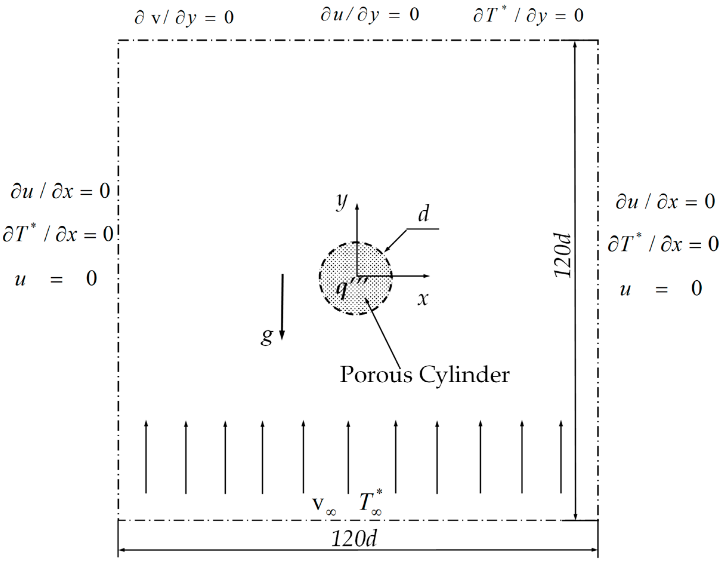
2. Problem Statement and Mathematical Formulation

The present problem with the computational domain is depicted in Figure 1, which shows a circular porous cylinder of diameter d exposed to a free stream with uniform velocity v and constant temperature T * . The velocity direction is consistent with the y direction, which is opposite to that of the gravity (g). This cylinder with heat generation (q′″) is placed at the center of the fictitious domain, whose center coincides with the origin of the coordinates (0, 0). The computational domain is a fixed square with a size 120 times the diameter of the cylinder, which is sufficiently large to reduce the effects of the inlet, outlet, and two lateral boundary conditions.
The governing equations, boundary conditions, and numerical results in the present study are presented in the non-dimensional forms. The diameter of cylinder (d), the incoming flow velocity v , and ρ v 2 are used as the length, velocity, and pressure scales, respectively. The non-dimensional temperature is based on both the temperature difference and the magnitude of heat generation. Therefore, the non-dimensional variables are defined as
X = x d ,   Y = y d ,   U = u v ,   V = v v ,   P = p ρ v 2 ,   T = T * T * q d 2 / k f ,
where x and y are the dimensional length in the horizontal and vertical directions, respectively, in Cartesian coordinates; u and v are the dimensional velocities along the x and y directions; p and T* are the pressure and temperature, respectively; kf is the thermal conductivity of fluid; X, Y, U, V, P, and T are the corresponding non-dimensional variables.
The Reynolds number is defined as
R e = v d υ ,
where υ is the fluid kinematic viscosity.
The Darcy number (Da) is based on the permeability and the diameter of the porous cylinder, which is defined as
D a = K d 2 ,
where K denotes the permeability of the porous cylinder.
In the thermal convection problem, the Richardson number is defined as
R i = G r R e 2 ,
where Gr is the Grashof number, which is expressed as Gr = gβq′″d5/kfυ2 for the heat-generation case. Here, β is the coefficient of thermal expansion.
Considering the two-dimensional, steady, and incompressible flow, the non-dimensional governing equations with the Boussinesq approximation and negligible dissipation can be expressed as the continuity equation
U X + V Y = 0 ,
the momentum equations
1 ε 2 ϕ ( U U X + V U Y ) = P X + 1 ε ϕ R e ( 2 U X 2 + 2 U Y 2 ) ϕ U R e D a ϕ 1.75 150 U 2 + V 2 D a U ε 3 / 2
1 ε 2 ϕ ( U V X + V V Y ) = P Y + 1 ε ϕ R e ( 2 V X 2 + 2 V Y 2 ) ϕ V R e D a ϕ 1.75 150 U 2 + V 2 D a V ε 3 / 2 + R i T
and the energy equation
U T X + V T Y = R c ϕ R e P r ( 2 T X 2 + 2 T Y 2 ) + ϕ R e P r ,
where ε is the porosity of the porous cylinder; Pr is the Prandtl number, defined as υ/α, where α is the thermal diffusivity; Rc is the ratio of thermal conductivity in the fluid saturated porous region, which is defined as ke/kf (ke is the effective thermal conductivity of fluid-saturated porous cylinder); ϕ is a binary constant, which is expressed as
ϕ = { 0 , for   fluid   region 1 ,   for   porous   region
The relevant boundary conditions used in the present study are presented in Figure 1. To obtain the closed forms of the governing equations, the interfacial boundary conditions for flow and heat transfer at the porous–fluid interface are needed. For the flow at the interface, the stress jump condition and continuities of velocity and normal stress are applied [36,37,38]. For heat transfer, the continuities of temperature and heat flux are implemented at the interface between porous and fluid regions. The detailed address for interfacial boundary conditions was provided by the studies of Yu et al. [39] and Chen et al. [40].

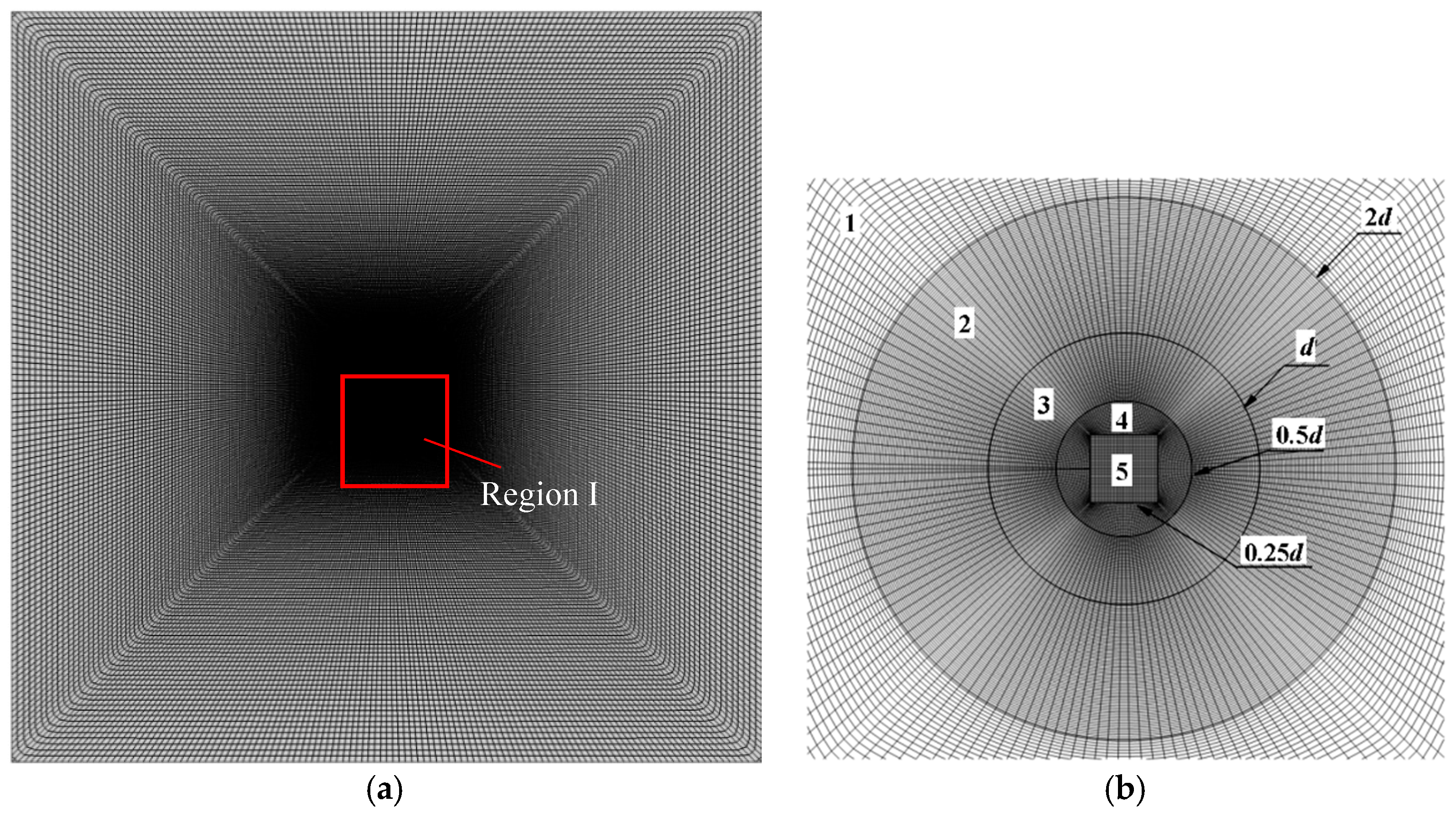
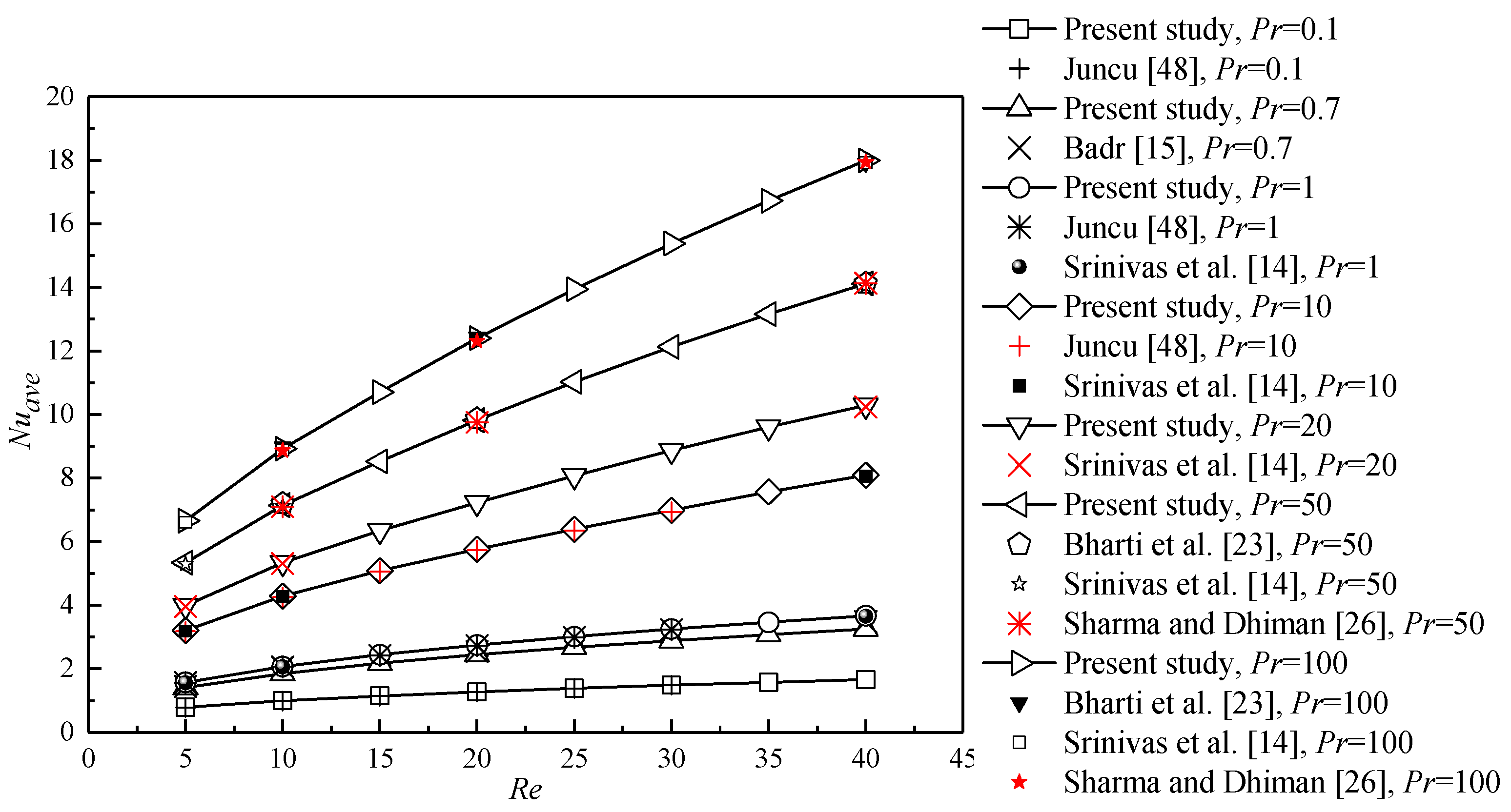
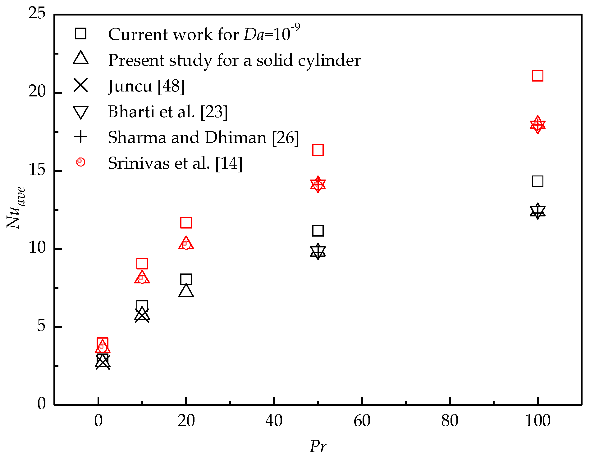
3. Grid-Independence Analysis and Code Validation

In the present study, a C++ code, originally developed by Yu et al. [39], based on the finite volume method with the collocated body-fitted and multi-block grids is adopted. The numerical simulations are performed in the Linux computing cluster system, which is equipped with total 1630 Intel(R) Xeon(R) Gold 6140 CPU processors (2.40 GHz/20 cores). To generate smooth body-fitted and structured grids around the porous cylinder surface, the whole computational domain is divided into five blocks. Blocks 1 and 2 comprise the pure fluid region, and blocks 3, 4, and 5 represent the porous regions. Blocks 2, 3, and 4 are meshed by using an O-grid to guarantee orthogonal grids around the cylinder surface with good quality. The grid for the whole computational domain is shown in Figure 2a. A closer view of Region I with mesh inside and around the porous cylinder and the domain partitioning is provided in Figure 2b.
The four sets of cases with different grid configurations presented in Table 1 are considered to conduct the grid-independence study. Numerical results of Nuave of such different grid configurations for Re = 40, Da = 10−4, Ri = 1, and Pr = 1 are also shown in Table 1. The grid convergence index (GCI) [41] is calculated to evaluate the grid convergence, which is expressed as
G C I = F s | E | ,
where Fs is a safety factor and is estimated to be 1.25 for three or more grid solutions [42,43]. E is a fine grid Richardson error estimator, which is defined as
E = ( f 2 f 1 ) / ( 1 r p ) ,
where f2 is a coarse grid solution with grid spacing h2, and f1 is a fine grid solution with grid spacing h1. The refinement factor r is calculated from h2/h1. p presents the formal order of accuracy of the algorithm. In this study, h1 and h2 are obtained from the grid spacing on the porous cylinder surface, and p is approximately two, owing to a second-order method [41].
Table 1 shows that the GCI (in round brackets) is less than 1% for all mesh configurations, which indicates that these four sets of grid configurations are fine for the present study. The GCI calculated from the third and fourth sets of grids is slightly larger than that from the second and third sets of grids, which may be due to the additional errors from the calculation and integration of the local Nusselt number. To ensure the better resolution and accuracy, the grid size of Case 4 is chosen for the final simulations.
The numerical model and method used in the present study have been successfully applied for the studies of flow around and through bluff porous bodies with various shapes [44,45,46,47] and heat transfer from a porous circular cylinder [18]. To further investigate the validity of the present numerical method, the computational simulations are performed for a heated solid cylinder with a constant surface temperature at different Pr. The local Nusselt number is defined as Nu = T n (n is the normal direction from the porous region to the fluid region), which is consistent with that for a solid cylinder with a constant surface temperature in the previous works. Figure 3 shows the Nuave of the present study as a function of Re at different Pr, which is in good agreement with the previous data provided by Juncu [48], Badr [15], Srinivas et al. [14], Bharti et al. [23], and Sharma and Dhiman [26].

4. Results and Discussions
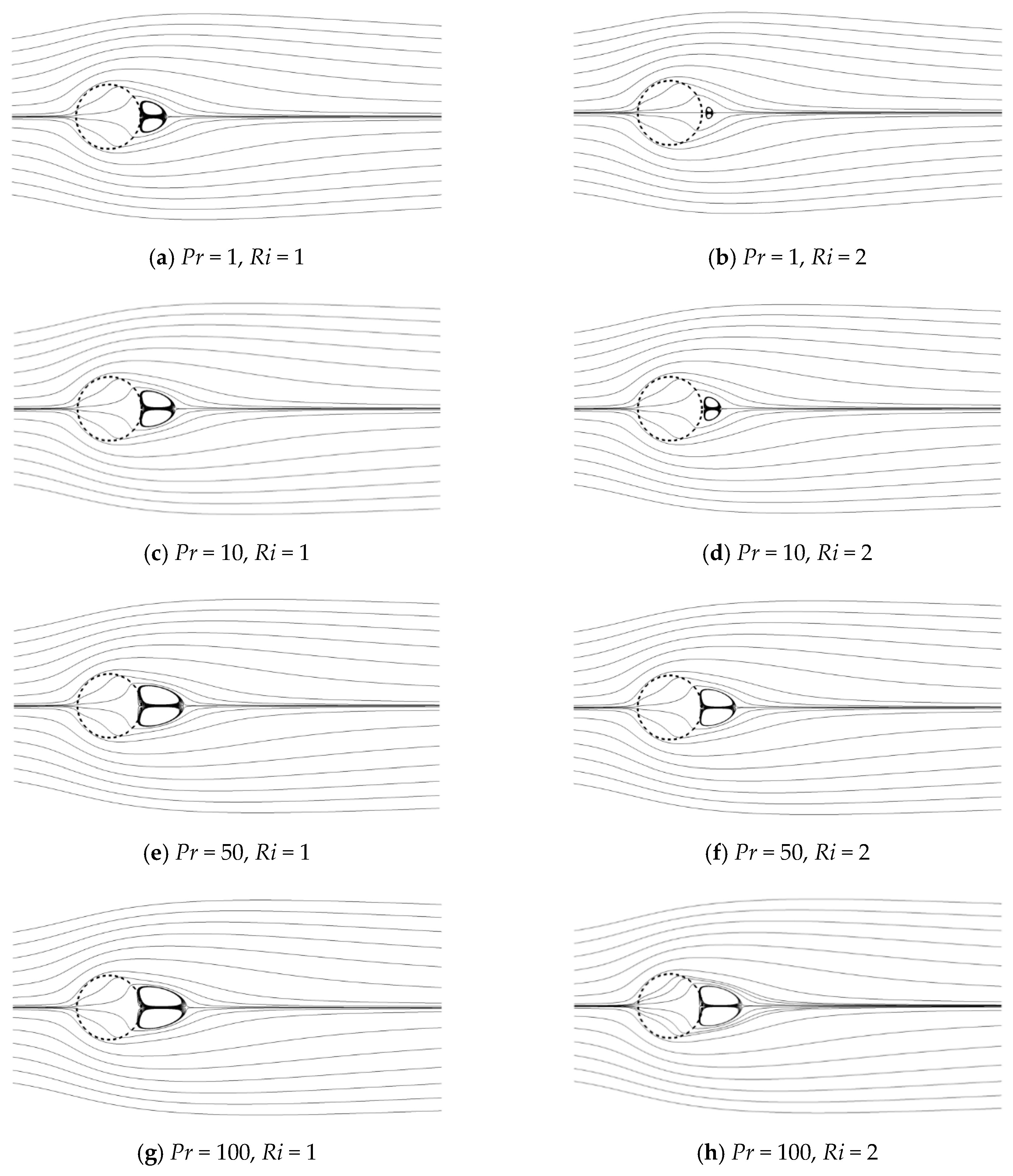
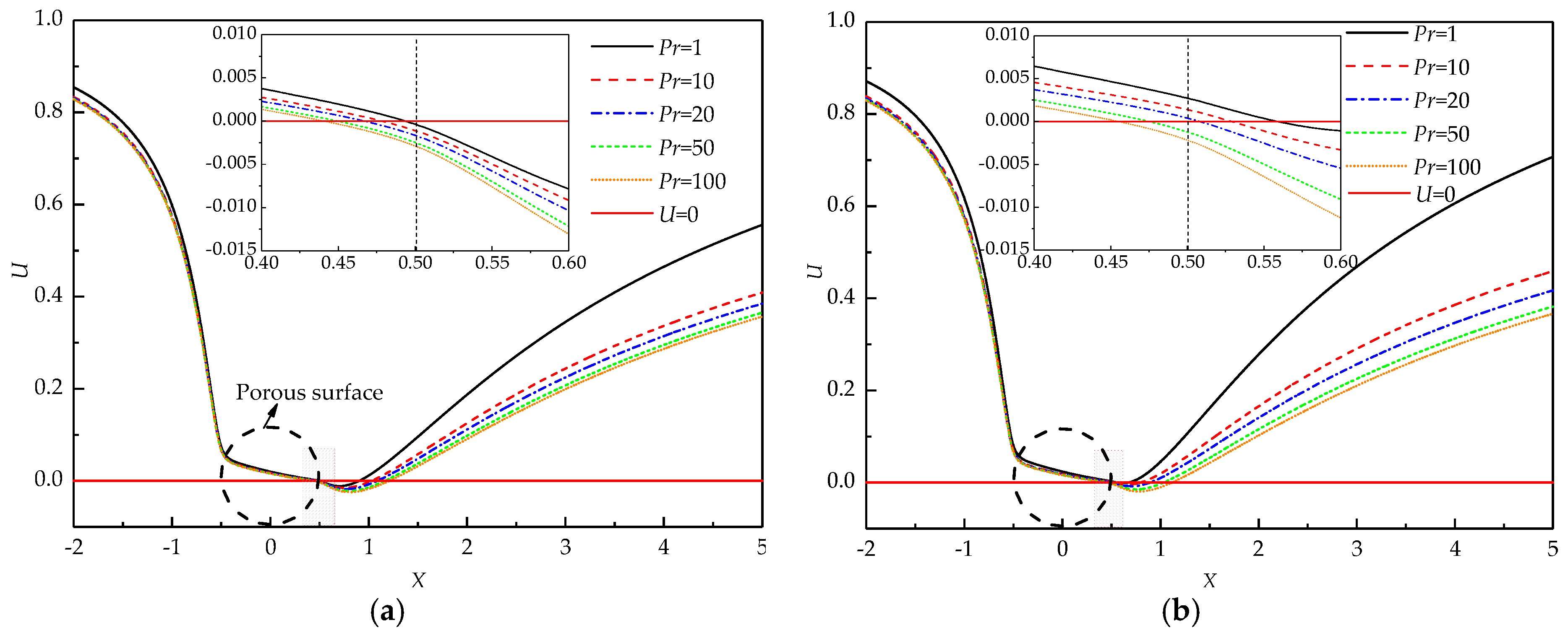
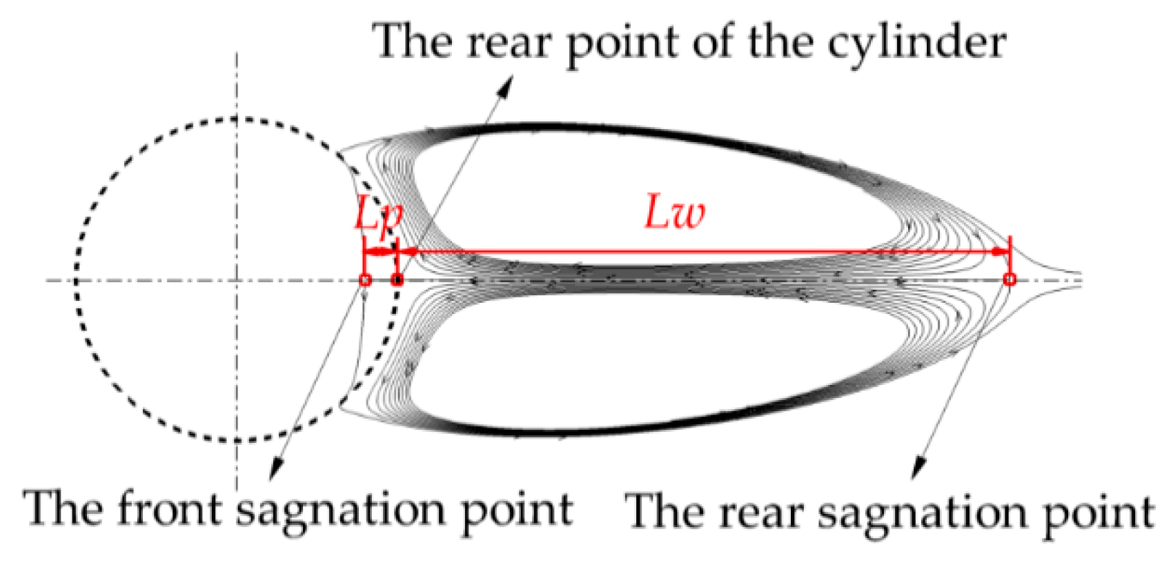
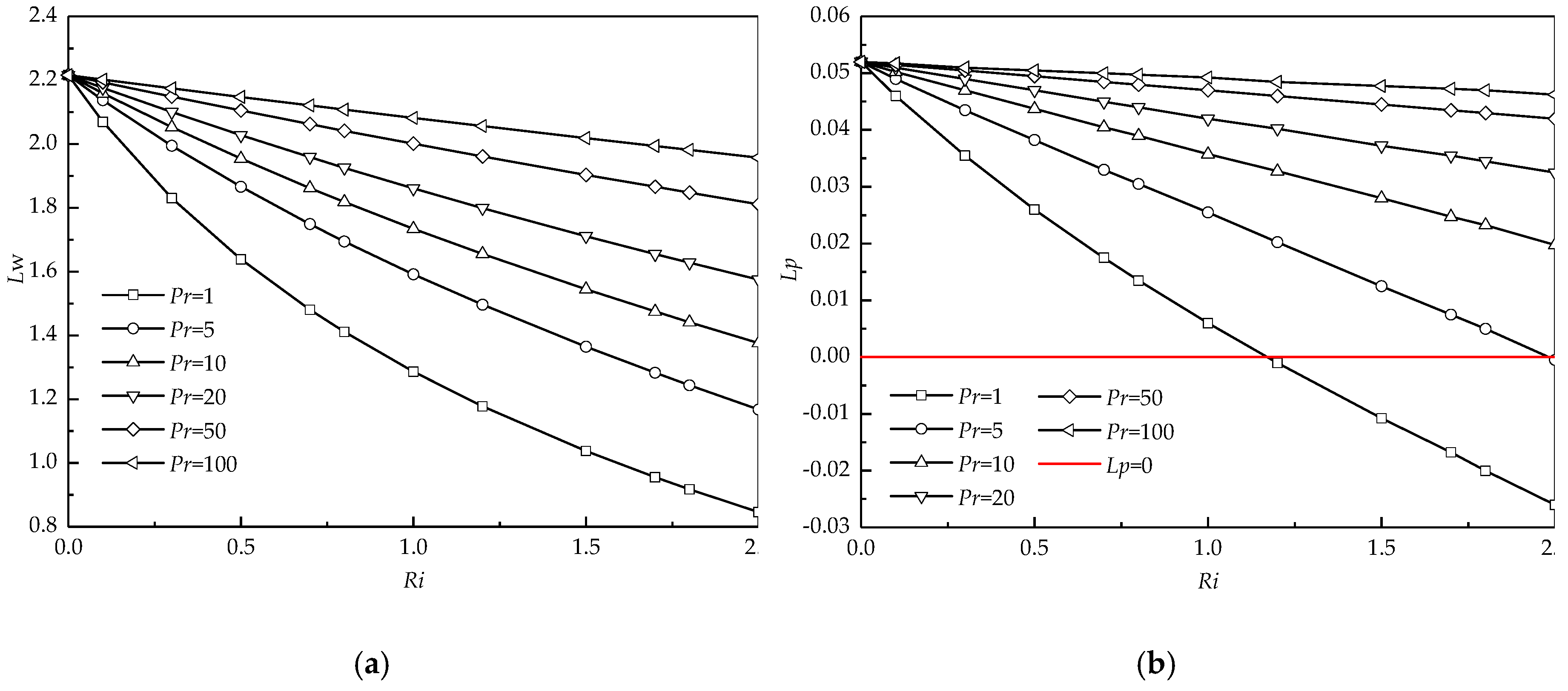
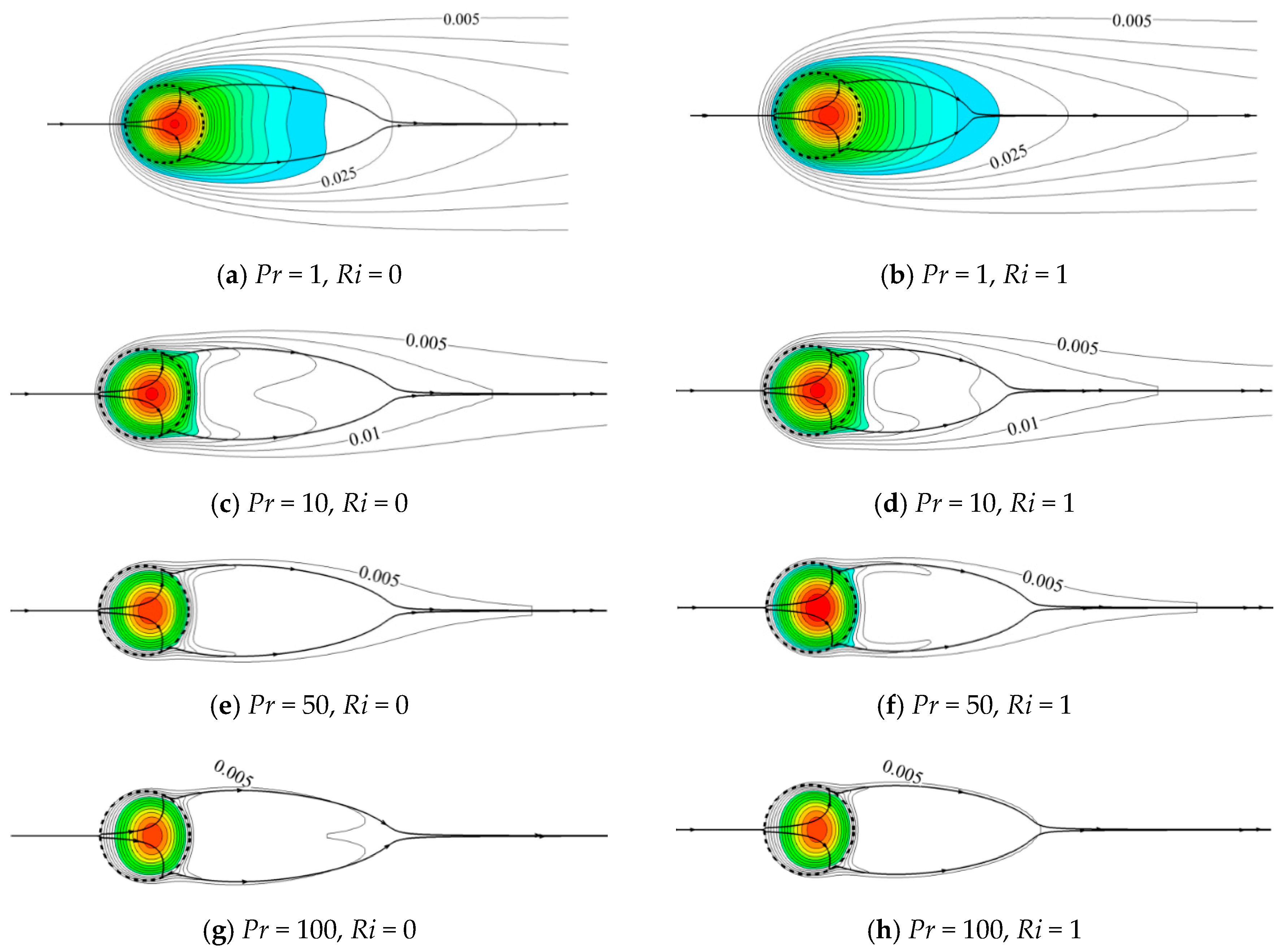
Numerical simulations are performed for different Pr (varying from 1 to 100 for different working fluids covering gas, water, light organic fluid, and oil) under the effects of Re, Da, and Ri, varying from 5 to 40, 10−6 to 10−2, and 0 to 2, respectively. The wake structure, temperature distribution, and heat transfer rate influenced by Pr in the mixed convection regime are mainly investigated. Note that the contours of the streamlines and isotherms are arranged horizontally for a better layout. The velocity direction is always consistent with the y direction while opposite to the gravity direction.

4.1. Flow Pattern

Figure 4 presents the effect of Pr on the flow pattern for Ri = 1 and 2 at constant Re = 20 and Da = 10−3. The left column presents the streamlines for Ri = 1. For this smaller Ri, a pair of recirculating wake forms and partially penetrates the porous cylinder from the rear in the present range of Pr. When Pr varies from 1 to 100, the recirculating wake is elongated along the flow direction and widened in the lateral sides. For a larger Ri = 2 shown in the right column, the size of the recirculating wake suffers from a reduction for all Pr compared to that for a smaller Ri. Especially at a small Pr, a pair of very small recirculating wakes occurs and is detached from the rear of the porous cylinder. When Pr increases, this recirculating wake moves toward the cylinder and finally also partially penetrates the rear surface at a large Pr. To some extent, Pr precipitates the growth of the recirculating wake.
To further investigate the variation of the wake structure with Pr, the U velocity distribution along the horizontal centerline of the porous cylinder at different Pr is depicted in Figure 5. A portion of fluid penetrates the cylinder with nonzero U velocity and bleeds from the rear part of the cylinder. The U velocity yielding from the surface resembles base bleed [49]. The bleeding from the cylinder partially satisfies the entrainment needs of the shear layer. Thus, the recirculating wake becomes narrower and shorter. The negative velocity is witnessed for all Pr at Re = 20, Da = 10−3, and Ri = 1 (see Figure 5a), which means the formation of the recirculating wake. The length of the region of the negative U velocity along the flow direction represents the whole length of the wake. An increase in Pr certainly results in an increment in the wake length. The negative exit velocity is also observed for all Pr, which indicates that a part of the recirculating wake penetrates the porous cylinder from the rear surface.
For a large Ri = 2 (see Figure 5b), the negative velocity occurs at a distance away from the cylinder for Pr ≤ 20, which means the formation of the detached recirculating wake. When Pr increases to 50 and 100, the exit velocity becomes negative, indicating that the recirculating wake partially penetrates the porous cylinder. The exit U velocity at the rear surface decreases with Pr, which indicates a reduction in base bleed. Less fluid is entrained into the near-wake region, which is incapable of supporting the shear flow. As a result, the large recirculating wake should form. Pr is defined as the ratio of momentum diffusivity to thermal diffusivity. When Pr increases but Re is fixed, the thickness of the thermal boundary layer decreases, which enhances the heat transfer rate. Therefore, much heat is carried away from the cylinder, and correspondingly, the temperature of the cylinder decreases. For a large Pr, the temperature is low due to the thin thermal boundary layer around the porous cylinder. Correspondingly, the buoyancy term becomes insignificant according to the Y-momentum equation, which weakens the effect of thermal buoyancy. Thus, the velocity of fluid flow decelerates. The large recirculating wake forms due to the insufficient entrainment.
Figure 6 presents a typical structure of a pair of the recirculating wakes. Different from the solid case, the front stagnation point of the recirculating wake may occur inside the porous cylinder. The distance from the front stagnation point of the recirculating wake to the rear point of the cylinder is defined as the penetration depth (Lp). The wake length (Lw) is measured by the distance from the rear point of the cylinder to the rear stagnation point of the recirculating wake. The entire length of the wake is the summation of Lw and Lp.
As stated above, Pr has a significant impact on the size of recirculating wake as well as the penetration depth. For this purpose, the detailed comparisons of variations of the wake length (Lw) and the penetration depth (Lp) with Ri at different Pr are presented in Figure 7. For all Ri (>0), Lw obviously increases with Pr. This increasing phenomenon becomes significant at large Ri (see Figure 7a). For all Pr, Lw presents a decreasing trend with increasing Ri. The variation of Lw with Ri becomes less sensitive when Pr increases, particularly at Pr = 100.
Figure 7b presents Lp as a function of Ri at different Pr. The variations of Lp with Pr and Ri are similar to those of Lw. It is worth noting that the negative Lp occurs for Pr ≤ 5 at Ri = 2. Negative Lp means the formation of the detached recirculating wake, as shown in Figure 4b. When Pr varies from 5 to 1, this negative Lp increases in magnitude, which indicates that the recirculating wake moves far away from the cylinder with decreasing Pr.

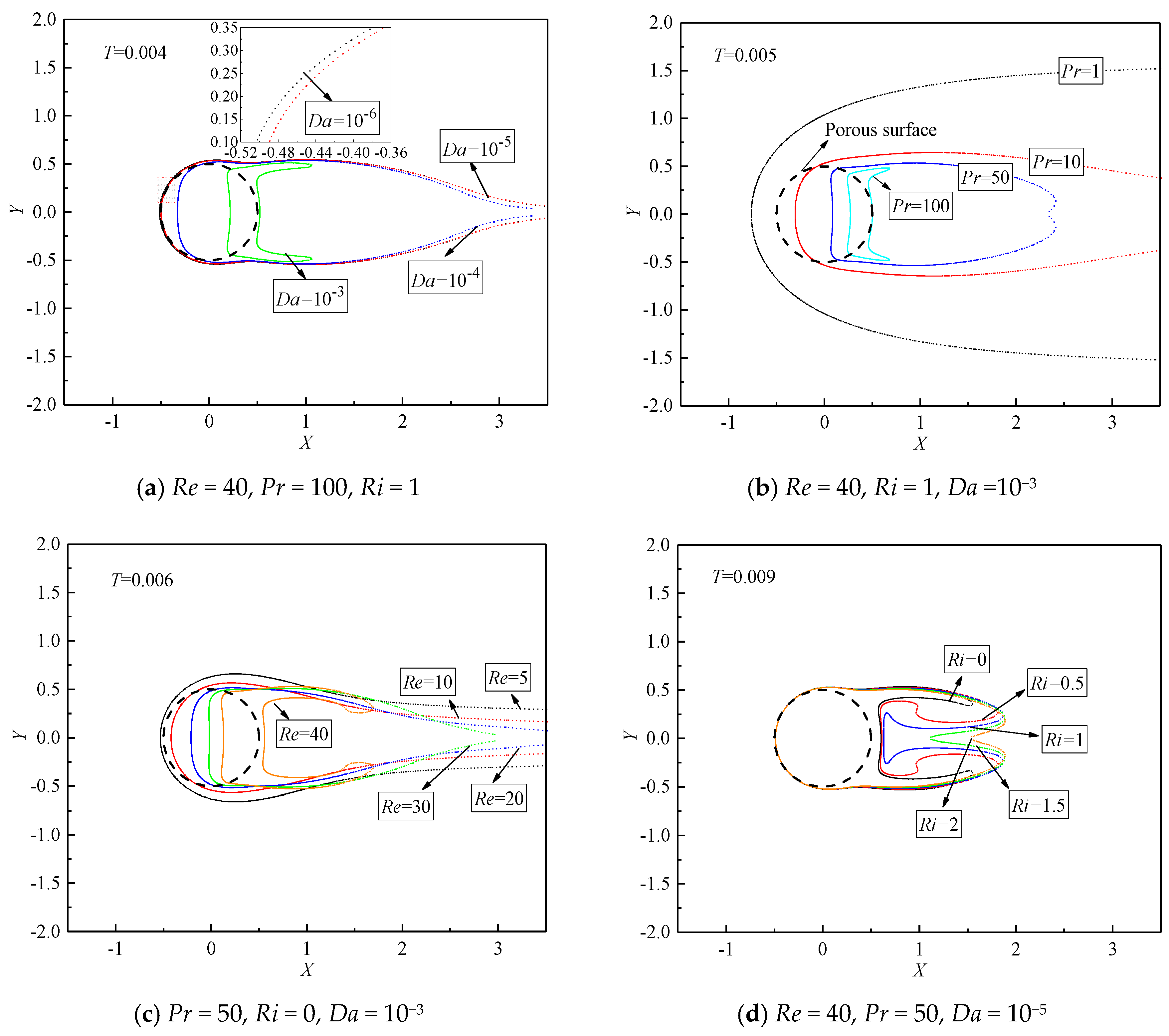
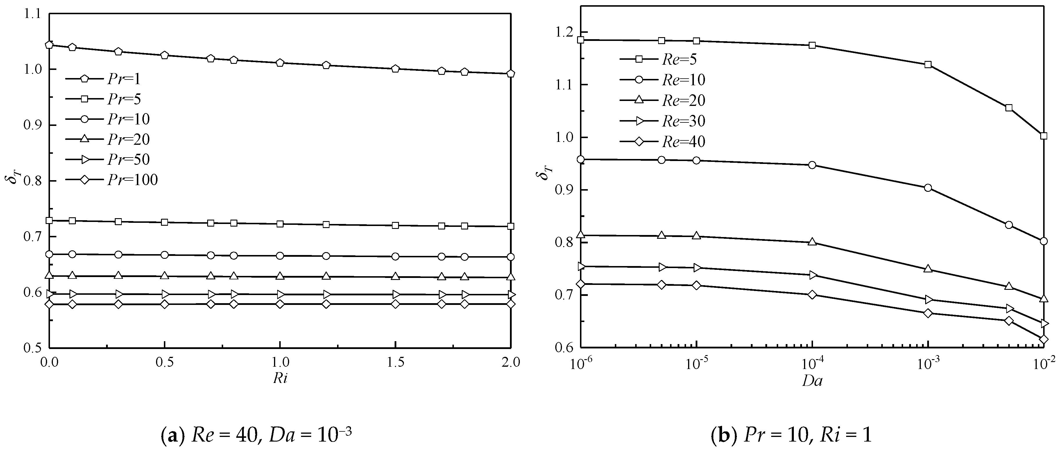
4.2. Temperature Field

Since there is a uniform heat source inside the porous cylinder, the compact isotherms distribute around the cylinder surface, especially at the front of the cylinder. Figure 8 shows the representative variations of thermal patterns with Pr and Ri at constant Re = 40 and Da = 10−5. To better understand the temperature distribution, only the isotherms for T ≥ 0.005 are presented. The colored contours are regarded as the thermal plume in our study, which is defined as the high temperature region for T ≥ 0.03. The temperature difference between two neighboring isotherms (∆T) is 0.005. The bold lines with arrowheads represent the streamlines. The left column illustrates the variations of isotherms with Pr in the forced convection regime (Ri = 0). Different from flow patterns, isotherms are significantly sensitive to Pr at Ri = 0. At a small Pr (for fixed Re), the thermal boundary layer is thick. Correspondingly, the temperature gradient is small, and isotherms sparsely distribute around the cylinder. The heat is also converted downstream by the fluid flow. Therefore, a large thermal plume with sparse isotherms around the cylinder is noticed at Pr = 1. When Pr increases, the thickness of the thermal boundary layer decreases. Correspondingly, the temperature gradient increases, and thus isotherms tightly assemble in the vicinity of the porous cylinder. An increase in the temperature gradient also results in an increment in the entropy generation, since the entropy generation is proportional to the temperature gradient [50]. Different from the smooth isotherms presented at small Pr = 1, the isotherms obviously bifurcate and become concave, resembling a saddle-shaped structure, behind the cylinder at a large Pr of 10. In this situation, swells of the isotherms pair off at the lateral sides, which almost align with the streamlines where the flow separation occurs [20]. Besides, a few of the isotherms embrace the cylinder surface, and the area surrounded by the isotherms decreases in size. With a further increase in Pr, these phenomena become more obvious. Moreover, at the largest Pr = 100, the isotherms start to become concave in shape at around lower T = 0.005 compared to other cases of smaller Pr, which indicates that the concave isotherms are more likely to occur with increasing Pr.
The right column presents the comparison of isotherms at different Pr in the mixed convection regime (Ri = 1). With the presence of thermal buoyancy, the additional momentum provided by buoyancy compels more fluid to carry away more heat from the cylinder. The isotherms shrink and embrace tightly the cylinder for a fixed Pr, which contributes to a larger temperature gradient. The thermal plume also becomes narrow in the lateral direction and evolves in the flow direction. Moreover, a smaller number of isotherms are observed behind the cylinder with increasing Pr. The isotherms also become denser with Pr, which indicates an increasing temperature gradient.
To further investigate the evolutions of the concave isotherms behind the porous cylinder in different conditions, the isotherms of T = 0.004, 0.005, 0.006, and 0.009 at various Da, Pr, Re, and Ri are illustrated in Figure 9. When the porous cylinder becomes much more permeable, a larger amount of fluid penetrates the porous cylinder and converts much more heat downstream, which is consistent with the cases of Figure 9a. The narrow and contractive isotherm is observed at Da = 10−3, which indicates a high temperature gradient. With a decrease in Da, the isotherm spatially grows in the lateral sides and stretches in the downstream direction. The obvious saddle-shaped isotherm is noticed at Da = 10−3, which indicates that the isotherms with lower T initially start to become concave in shape at larger Da compared to the cases of lower Da. Indeed, this phenomenon is also valid for other cases of different Re, Pr, and Ri.
Figure 9b shows the variations of the isothermal structure (T = 0.005) with Pr at constant Re = 40, Ri = 1, and Da = 10−3. At the same temperature level, the occurrence of the concave isotherm is witnessed at higher Pr. As presented in Figure 9b, the isotherm of T = 0.005 becomes concave behind the cylinder for Pr ≥ 50. When Pr increases, the concave isotherms become significant, and the lateral distribution of the isotherm obviously reduces in width. Similar phenomena are also observed when considering the effect of Re on the variation of isotherms, as shown in Figure 9c. The concave structure of the isotherm is highlighted at higher Re = 40. A different trend is seen for Ri variation (Figure 9d). The thermal buoyancy attempts to relax and soothe the concave structure of the isotherms. At Ri = 0, the isotherm of T = 0.009 obviously bifurcates and becomes concave. With an increase in Ri, these swells of the isotherms tend to expand toward the horizontal centerline and spread in the downstream direction, which interprets the phenomenon for Ri varying from 0 to 1 at Pr = 50, as shown in Figure 8. Eventually, the concave isotherms behind the cylinder tend to relax at larger Ri.
As stated above, the isotherms spatially expand or shrink in the lateral sides in the influences of various Da, Pr, Re, and Ri. Changes of the isotherms in space also result in the variation of the thermal boundary layer. Therefore, the thermal boundary layer thickness is analyzed in the present study. The thickness of the thermal boundary layer (δT) at any location along the surface is defined as the distance from the surface at which the temperature difference T* T s * = 0.99( T * T s * ) [51]. Generally, the thermal boundary layer thickness increases in the flow direction for a steady flow around a cylinder. The thermal boundary layer thickness at a specific surface point ((X, Y) = (0, 0.5)) is monitored. The results are presented in Figure 10.
Figure 10a shows δT as a function of Ri at different Pr for the case at constant Re = 40 and Da = 10−3. For all Pr, δT varies monotonously and linearly with Ri. For a small Pr, δT obviously experiences a reduction with an increase in Ri. The thermal buoyancy provides additional momentum for the fluid, the flow is accelerated, and more heat is carried away at this specific surface point. Therefore, the thermal boundary layer should attenuate around the surface. For a large Pr, this decreasing trend of δT with Ri becomes insignificant. Particularly for a large Pr, for example Pr = 100, a negligible variation in δT with increasing Ri is observed, which indicates that the effect of thermal buoyancy on the formation of the thermal boundary layer can be neglected. For all Ri, δT shows a significant reduction with increasing Pr. These observations are similar to and also confirm those of the variation of isotherms with Pr presented in Figure 8 and Figure 9. With an increase in Pr, heat convection is more significant compared to heat conduction. More heat is effectively transferred downstream from the porous cylinder by convection. This eventually results in a reduction in the thermal boundary layer thickness.
The comparisons of the variation of δT with Da at different Re for Pr = 10 and Ri = 1 are depicted in Figure 10b. For all Re studied here, δT gradually decreases when Da increases. For a less permeable cylinder at a fixed Re, less fluid passes through the cylinder, and only a small part of heat can be transferred downstream. As a result, much heat is stored inside the cylinder, and the thermal boundary layer thickens around the cylinder surface. When the cylinder becomes more permeable, the resistance of the porous cylinder to the fluid becomes less significant. Correspondingly, the fluid velocity is accelerated, and the velocity gradient decreases, which leads to a reduction in the entropy production due to the viscous effect [50]. This accelerated fluid results in a large amount of convective heat transfer in this system, which ultimately narrows the temperature contours in the lateral sides (see Figure 8 and Figure 9) and thins the thermal boundary layer along the surface. For all Da, δT also shows a descending tendency when Re increases. For constant Pr, Ri, and Da and lower Re, the fluid velocity is relatively smaller, and heat transfer is mainly dominated by conduction. When Re becomes larger, fluid movement becomes pronounced, owing to the relatively larger inertial force, and convection is dominant in this situation. Correspondingly, the thermal boundary layer decreases, which also indicates a growth in entropy production owing to the increasing temperature gradient.

4.3. Heat Transfer Rate

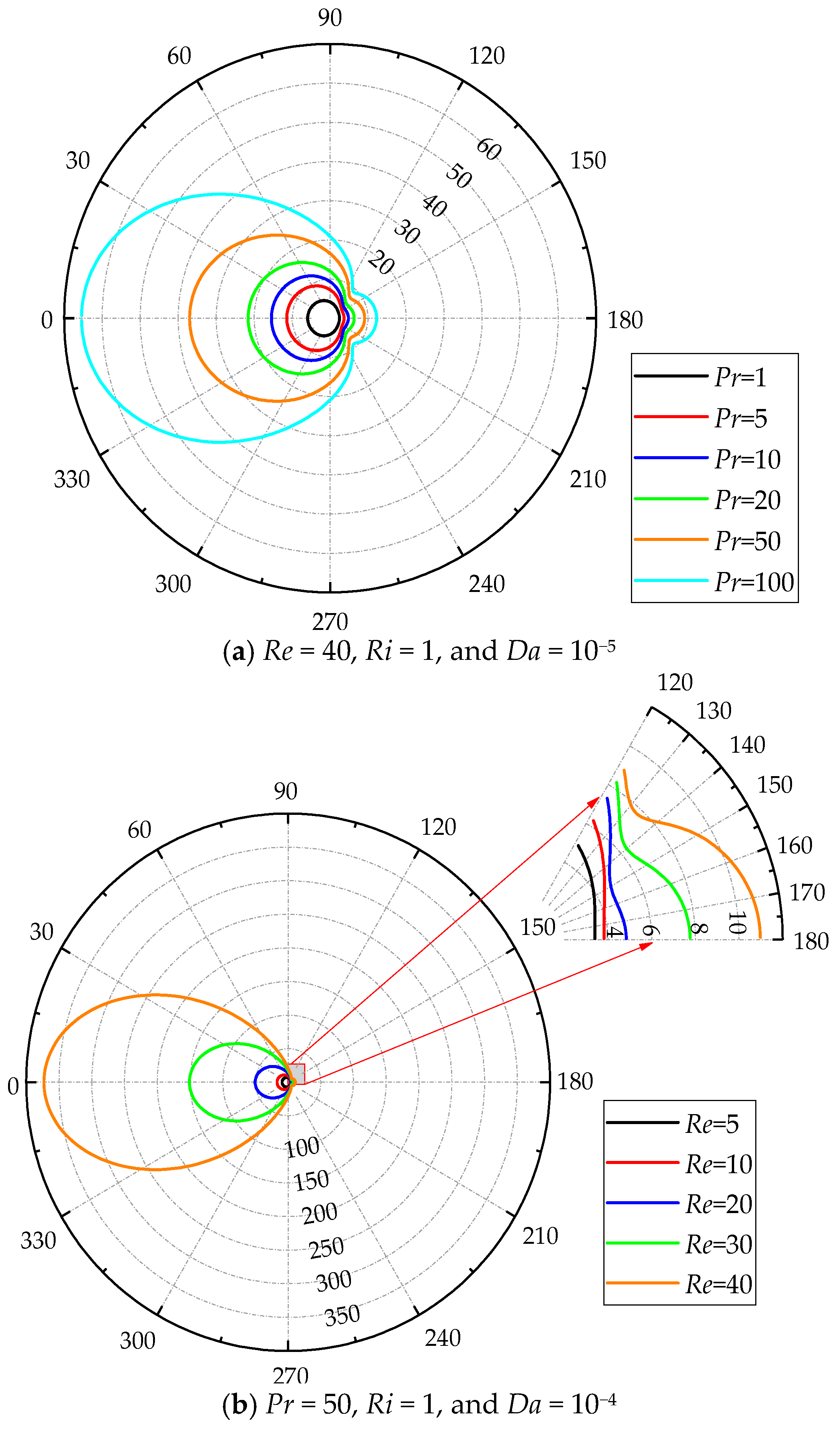
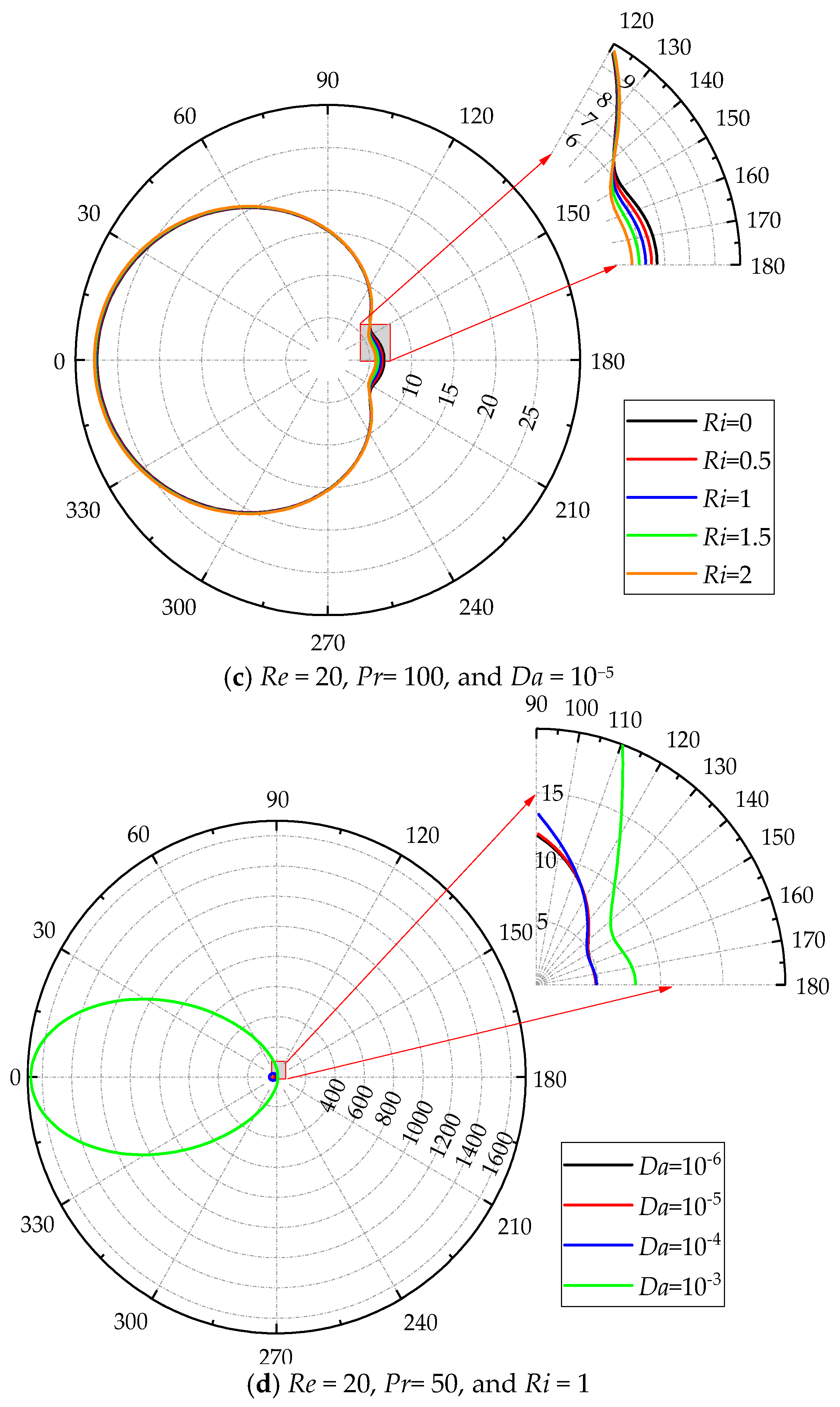
4.3.1. Local Nusselt Number

The Nusselt number (Nu) is a non-dimensional parameter to characterize the heat transfer rate in a thermal system, which is defined as
N u = h d k f = 1 4 T | i n t e r f a c e ,
where h is the heat transfer coefficient. The local heat transfer performance quantified by the local Nusselt number (Nu) along the porous cylinder surface is shown in Figure 11. To better present the distribution of Nu along the cylinder surface, the polar coordinate is chosen. The numbers distributed in the radial direction represents the magnitude of Nu.
Figure 11a shows the variations of Nu for different Pr at Re = 40, Ri = 1, and Da = 10−5. Large Nu is certainly noticed at the front of the cylinder for all Pr. For a small Pr, Nu gradually decreases along the cylinder surface from the front to the rear. The minimum Nu is found at the rear point. However, there is a jump in the distribution of Nu along the cylinder surface for a large Pr, i.e., Nu initially decreases and then increases from the front to the rear. The minimum Nu is just observed at the location where the jump occurs. When Pr increases, this phenomenon is significant. The positions of the occurrence of the jump in the distribution of Nu are in accordance with those of the onset of swells of the isotherms shown in Figure 8. Across this position, the crowded isotherms distribute near the cylinder, resulting in an increase in the temperature gradient. Therefore, Nu increases after the jump location. Moreover, the jump location is found to move upstream along the cylinder surface when Pr increases, which indicates that the positions of the onset of swells of the isotherms are greatly dependent on Pr in this situation. A similar observation is also identified for different Re shown in Figure 11b.
The variation of Nu with Ri is illustrated for a large Pr = 100 and constant Re = 20 and Da = 10−5 in Figure 11c. Different from the case of small Pr (see reference [18]), there is a turning point in the distribution of Nu along the cylinder surface, across which the trend of variation of Nu with increasing Ri becomes opposite. The concave isotherms behind the cylinder are relaxed and smoothed when Ri increases, which causes an increase in the distance between two neighboring isotherms behind the cylinder (see Figure 8 and Figure 9). As a result, the temperature gradient decreases. Therefore, Nu decreases with Ri after the turning point. The effect of Da on Nu along the cylinder surface at a larger Pr = 50 is shown in Figure 11d. Nu increases with Da at the front part of the cylinder. However, the distributions of the isotherms at the rear varying with Da are more complicated owing to the concave structure of the isotherms at larger Pr.

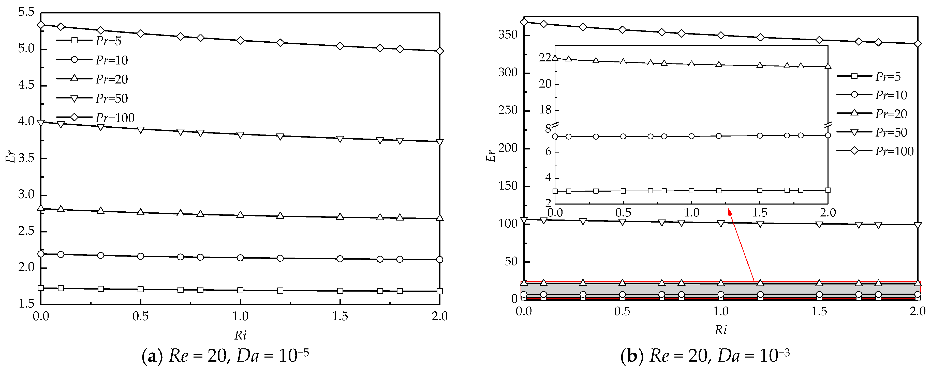
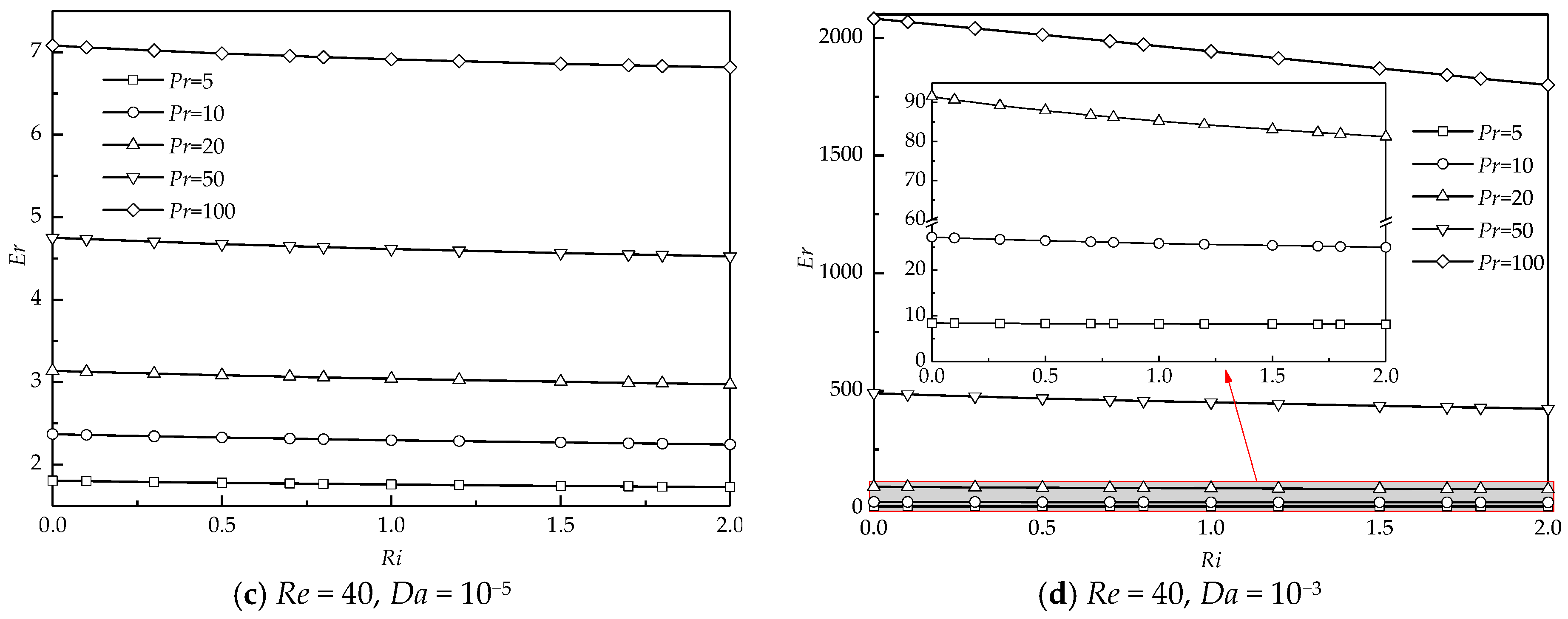
4.3.2. Enhancement Ratio

The average Nusselt number (Nuave) is defined as
N u a v e = 1 A A N u d A ,
where A is the surface area.
When Da is rather small, the cylinder almost becomes impermeable. To investigate the heat transfer difference between the present work for a porous cylinder with internal heat generation and the previous works for a solid cylinder with a constant surface temperature, the case of Da = 10−9 is performed for different Pr and Re. Simulations for flow around a solid cylinder with constant surface temperature are also carried out by the present method. The comparisons of the current results with the previous results for different Pr at Re = 20 (black scatters) and 40 (red scatters) in the forced convection regime (Ri = 0) are shown in Figure 12. It is seen that for a fixed Re, Nuave for Da = 10−9 in the present study is larger than that of the previous works for all Pr studied here. When Da increases, more fluid can penetrate the porous cylinder, which converts more heat downstream. Therefore, Nuave for larger Da is much higher than that for the solid cylinder.
To better depict the enhancement of heat transfer, the ratio of the average Nusselt number at various Pr (Nuave) to that at Pr = 1 (Nu*ave) is defined as the enhancement ratio (Er) = Nuave/Nu*ave. The variation of Er with Ri at different Pr, Re, and Da is illustrated in Figure 13. Er almost varies monotonously and linearly with increasing Ri for all Pr, Re, and Da. Figure 13a,b present the results at a smaller Re = 20. For a smaller Da =10−5 shown in Figure 13a, the variation of Er with Ri is insignificant for a small Pr. For a large Pr, the decreasing tendency of Er with Ri becomes significant, which means that changes in the strength of the thermal buoyancy at a large Pr have a relatively significant effect on Er compared to those at a small Pr. For all Ri, Er shows an increasing trend with Pr. An increase in Pr certainly decreases the thickness of the thermal boundary layer around the cylinder presented in Figure 10a, which significantly enhances the heat transfer rate. Similar results of the variation of Er with Ri at different Pr are also obtained at a larger Da = 10−3 (see Figure 13b).
Figure 13c,d show the dependence of Er on Ri and Pr at a larger Re = 40. For a less permeable case of Da =10−5 shown in Figure 13c, at a fixed Ri and Pr, the magnitude of Er increases compared to that at Re = 20, owing to the decreasing thickness of the thermal boundary layer at a larger Re shown in Figure 10b. When the cylinder becomes more permeable (see Figure 13d), Er significantly increases compared to that for Da =10−5 at constant Ri and Pr. However, the decreasing trend of Er with Ri is obviously witnessed, especially at a large Pr.

5. Conclusions

The present study numerically reveals the effect of the Prandtl number on the flow and heat transfer through and around a porous cylinder with internal heat generation in the mixed convection regime. The wake structure in terms of the streamlines, the wake length, the penetration depth, the isotherms, the boundary layer thickness, and the heat transfer rate characterized by the Nusselt number and enhancement ratio are mainly investigated in detail.
The numerical results show that a pair of the detached recirculating wakes occurs at an intermediate Da for a large Ri and a small Pr owing to the large base bleed. For a small Ri and a large Pr, the recirculating wake partially penetrates the porous cylinder. At a fixed Re, Pr is found to precipitate the growth of the recirculating wake. An increase in Pr weakens the effect of thermal buoyancy, which results in a reduction in the velocity through the porous cylinder and directly decreases the effect of base bleed. Less bleeding from the rear is not enough to support the entrainment need of the shear layer. Therefore, the large recirculating wake occurs.
The thermal field is significantly sensitive to Pr. For a small Pr, smooth isotherms sparely and widely enwrap the porous cylinder due to the relative dominance of thermal conduction. When Pr increases, the isotherms are no longer obedient, and they become concave in shape behind the cylinder. For a large Pr, these concave isotherms are significantly highlighted. Similar results are also observed with an increase in Re. The positions of the occurrence of swells of the isotherms almost match the streamlines where the flow separation occurs. Moreover, the present results suggest that the isotherms with lower temperature initially become concave for a larger Da. Thermal buoyancy provides the additional momentum to this system and tends to appease and relax the concave structure of the isotherms.
The local heat transfer rate is witnessed to minimize at the position where swells of the isotherms form. After this position, dense isotherms distribute near the cylinder, which results in a relatively large temperature gradient. Therefore, the local heat transfer rate increases across this position. An increase in Pr means that there is a much thinner thermal boundary layer relative to the momentum boundary layer. The thin thermal boundary layer results in a large temperature gradient. Thus, the heat transfer rate enhances.

Author Contributions

Data curation, formal analysis, software, investigation, validation, and writing—original draft preparation and review and editing, S.Y.; formal analysis, writing—review and editing, T.T. and J.L.; conceptualization, supervision, methodology, software, and writing—review and editing, P.Y. All authors have read and agreed to the published version of the manuscript.

Funding

The authors would like to thank the financial support from the National Natural Science Foundation of China (NSFC, Grant No. 11672124), Shenzhen Key Laboratory of Complex Aerospace Flows (Grant No. ZDSYS201802081843517), the Shenzhen Peacock Plan (Grant No. KQTD2016022620054656), and Guangdong Provincial Key Laboratory of Turbulence Research and Applications (Grant No. 2019B21203001).

Acknowledgments

The authors thank the computational resources provided by the Center for Computational Science and Engineering, Southern University of Science and Technology.

Conflicts of Interest

The authors declare no conflict of interest.

Abbreviations

Nomenclature
ggravitational acceleration, [m/s2]
q′″heat source, [W/m3]
ddiameter of cylinder, [m]
Asurface area, [m2]
Kpermeability of cylinder, [m2]
kfthermal conductivity of fluid, [W/(m·°C)]
keeffective thermal conductivity, [W/(m·°C)]
Rcthermal conductivity ratio
hheat transfer coefficient, [W/(m2·°C)]
xdimensional horizontal coordinate, [m]
ydimensional vertical coordinate, [m]
udimensional x-component velocity, [m/s]
vdimensional y-component velocity, [m/s]
ppressure, [Pa]
T*temperature, [°C]
Xdimensionless horizontal coordinate
Ydimensionless vertical coordinate
Udimensionless x-component velocity
Vdimensionless y-component velocity
Pdimensionless pressure
Tdimensionless temperature
Lwthe wake length
Lpthe penetration depth
ReReynolds number
PrPrandtl number
GrGrashof number
RiRichardson number
DaDarcy number
NuNusselt number
Erenhancement ratio
nthe dimensionless normal direction
Greek symbols
αthermal diffusivity, [m2/s]
βthermal expansion coefficient, [°C−1]
υfluid kinematic viscosity, [m2/s]
εfluid kinematic viscosity porosity
ρfluid density, [kg/m3]
δthe thickness of the thermal boundary layer
ϕ a binary constant
Subscripts
free stream
aveaverage

References

  1. Nield, D.A.; Bejan, A. Convection in Porous Media; Springer: New York, NY, USA, 2006; Volume 3. [Google Scholar]
  2. Vadász, P. Emerging Topics in Heat and Mass Transfer in Porous Media: From Bioengineering and Microelectronics to Nanotechnology; Springer Science & Business Media: New York, NY, USA, 2008; Volume 22. [Google Scholar]
  3. Seo, J.-W.; Kim, Y.-H.; Kim, D.; Choi, Y.-D.; Lee, K.-J. Heat transfer and pressure drop characteristics in straight microchannel of printed circuit heat exchangers. Entropy 2015, 17, 3438–3457. [Google Scholar] [CrossRef]
  4. Ma, H.; Duan, Z.; Su, L.; Ning, X.; Bai, J.; Lv, X. Fluid flow and entropy generation analysis of Al2O3—Water nanofluid in microchannel plate fin heat sinks. Entropy 2019, 21, 739. [Google Scholar] [CrossRef] [Green Version]
  5. Mahdi, R.A.; Mohammed, H.; Munisamy, K.; Saeid, N. Review of convection heat transfer and fluid flow in porous media with nanofluid. Renew. Sustain. Energy Rev. 2015, 41, 715–734. [Google Scholar] [CrossRef]
  6. Smakulski, P.; Pietrowicz, S. A review of the capabilities of high heat flux removal by porous materials, microchannels and spray cooling techniques. Appl. Therm. Eng. 2016, 104, 636–646. [Google Scholar] [CrossRef]
  7. Chen, H.; Zheng, Z.; Chen, Z.; Bi, X. A lattice gas automata model for the coupled heat transfer and chemical reaction of gas flow around and through a porous circular cylinder. Entropy 2016, 18, 2. [Google Scholar] [CrossRef] [Green Version]
  8. Dhinakaran, S.; Ponmozhi, J. Heat transfer from a permeable square cylinder to a flowing fluid. Energy Convers. Manag. 2011, 52, 2170–2182. [Google Scholar] [CrossRef]
  9. Rashidi, S.; Hayatdavoodi, M.; Esfahani, J.A. Vortex shedding suppression and wake control: A review. Ocean Eng. 2016, 126, 57–80. [Google Scholar] [CrossRef] [Green Version]
  10. Al-Sumaily, G.F.; Thompson, M.C. Forced convection from a circular cylinder in pulsating flow with and without the presence of porous media. Int. J. Heat Mass Transf. 2013, 61, 226–244. [Google Scholar] [CrossRef]
  11. Hu, H.; Koochesfahani, M. Thermal effects on the wake of a heated circular cylinder operating in mixed convection regime. J. Fluid Mech. 2011, 685, 235–270. [Google Scholar] [CrossRef] [Green Version]
  12. Ahmad, R.; Qureshi, Z. Laminar mixed convection from a uniform heat flux horizontal cylinder in a crossflow. J. Thermophys. Heat Transf. 1992, 6, 277–287. [Google Scholar] [CrossRef]
  13. Mohammed, H.A.; Salman, Y.K. Experimental investigation of mixed convection heat transfer for thermally developing flow in a horizontal circular cylinder. Appl. Therm. Eng. 2007, 27, 1522–1533. [Google Scholar] [CrossRef]
  14. Srinivas, A.T.; Bharti, R.P.; Chhabra, R.P. Mixed convection heat transfer from a cylinder in power-law fluids: Effect of aiding buoyancy. Ind. Eng. Chem. Res. 2009, 48, 9735–9754. [Google Scholar] [CrossRef]
  15. Badr, H. A theoretical study of laminar mixed convection from a horizontal cylinder in a cross stream. Int. J. Heat Mass Transf. 1983, 26, 639–653. [Google Scholar] [CrossRef]
  16. Sharma, N.; Dhiman, A.K.; Kumar, S. Mixed convection flow and heat transfer across a square cylinder under the influence of aiding buoyancy at low Reynolds numbers. Int. J. Heat Mass Transf. 2012, 55, 2601–2614. [Google Scholar] [CrossRef]
  17. Wu, H.-W.; Wang, R.-H. Mixed convective heat transfer past a heated square porous cylinder in a horizontal channel with varying channel height. J. Heat Transf. 2011, 133. [Google Scholar] [CrossRef]
  18. Yu, S.; Yu, P.; Tang, T. Effect of thermal buoyancy on flow and heat transfer around a permeable circular cylinder with internal heat generation. Int. J. Heat Mass Transf. 2018, 126, 1143–1163. [Google Scholar] [CrossRef]
  19. Dhiman, A.; Chhabra, R.; Sharma, A.; Eswaran, V. Effects of Reynolds and Prandtl numbers on heat transfer across a square cylinder in the steady flow regime. Numer. Heat Transf. 2006, 49, 717–731. [Google Scholar] [CrossRef]
  20. Ajith Kumar, S.; Mathur, M.; Sameen, A.; Anil Lal, S. Effects of Prandtl number on the laminar cross flow past a heated cylinder. Phys. Fluids 2016, 28, 113603. [Google Scholar] [CrossRef]
  21. Dennis, S.C.R.; Hudson, J.; Smith, N. Steady laminar forced convection from a circular cylinder at low Reynolds numbers. Phys. Fluids 1968, 11, 933–940. [Google Scholar] [CrossRef]
  22. Vilimpoq, V.; Cole, R.; Sukanek, P. Heat transfer in Newtonian liquids around a circular cylinder. Int. J. Heat Mass Transf. 1990, 33, 447–456. [Google Scholar] [CrossRef]
  23. Bharti, R.P.; Chhabra, R.; Eswaran, V. A numerical study of the steady forced convection heat transfer from an unconfined circular cylinder. Heat Mass Transf. 2007, 43, 639–648. [Google Scholar] [CrossRef]
  24. Dhiman, A.; Chhabra, R.; Eswaran, V. Flow and heat transfer across a confined square cylinder in the steady flow regime: Effect of Peclet number. Int. J. Heat Mass Transf. 2005, 48, 4598–4614. [Google Scholar] [CrossRef]
  25. Sahu, A.K.; Chhabra, R.; Eswaran, V. Effects of Reynolds and Prandtl numbers on heat transfer from a square cylinder in the unsteady flow regime. Int. J. Heat Mass Transf. 2009, 52, 839–850. [Google Scholar] [CrossRef]
  26. Sharma, V.; Dhiman, A.K. Heat transfer from a rotating circular cylinder in the steady regime: Effects of Prandtl number. Therm. Sci 2012, 16, 79–91. [Google Scholar] [CrossRef]
  27. Chen, Q.; Zhang, X.; Zhang, J. Effects of Reynolds and Prandtl numbers on heat transfer around a circular cylinder by the simplified thermal lattice Boltzmann model. Commun. Comput. Phys. 2015, 17, 937–959. [Google Scholar] [CrossRef]
  28. Sufyan, M.; Manzoor, S.; Sheikh, N.A. Free stream flow and forced convection heat transfer across rotating circular cylinder in steady regime: Effects of rotation, Prandtl number and thermal boundary condition. J. Mech. Sci. Technol. 2015, 29, 1781–1797. [Google Scholar] [CrossRef]
  29. Kim, S.J.; Jang, S.P. Effects of the Darcy number, the Prandtl number, and the Reynolds number on local thermal non-equilibrium. Int. J. Heat Mass Transf. 2002, 45, 3885–3896. [Google Scholar] [CrossRef]
  30. Anirudh, K.; Dhinakaran, S. Effects of Prandtl number on the forced convection heat transfer from a porous square cylinder. Int. J. Heat Mass Transf. 2018, 126, 1358–1375. [Google Scholar] [CrossRef]
  31. Khan, A.; Khan, D.; Khan, I.; Taj, M.; Ullah, I.; Aldawsari, A.M.; Thounthong, P.; Sooppy Nisar, K. MHD Flow and Heat Transfer in Sodium Alginate Fluid with Thermal Radiation and Porosity Effects: Fractional Model of Atangana–Baleanu Derivative of Non-Local and Non-Singular Kernel. Symmetry 2019, 11, 1295. [Google Scholar] [CrossRef] [Green Version]
  32. Steinberg, D.S. Cooling Techniques for Electronic Equipment; Wiley-Interscience: New York, NY, USA, 1980; p. 387. [Google Scholar]
  33. Hardee, H.; Nilson, R. Natural convection in porous media with heat generation. Nucl. Sci. Eng. 1977, 63, 119–132. [Google Scholar] [CrossRef]
  34. Ismagilov, Z.; Pushkarev, V.; Podyacheva, O.Y.; Koryabkina, N.; Veringa, H. A catalytic heat-exchanging tubular reactor for combining of high temperature exothermic and endothermic reactions. Chem. Eng. J. 2001, 82, 355–360. [Google Scholar] [CrossRef]
  35. Khan, U.; Zaib, A.; Khan, I.; Nisar, K.S. Activation energy on MHD flow of titanium alloy (Ti6Al4V) nanoparticle along with a cross flow and streamwise direction with binary chemical reaction and non-linear radiation: Dual Solutions. J. Mater. Res. Technol. 2019. [Google Scholar] [CrossRef]
  36. Ochoa-Tapia, J.A.; Whitaker, S. Momentum transfer at the boundary between a porous medium and a homogeneous fluid—I. Theoretical development. Int. J. Heat Mass Transf. 1995, 38, 2635–2646. [Google Scholar] [CrossRef]
  37. Ochoa-Tapia, J.A.; Whitaker, S. Momentum transfer at the boundary between a porous medium and a homogeneous fluid—II. Comparison with experiment. Int. J. Heat Mass Transf. 1995, 38, 2647–2655. [Google Scholar] [CrossRef]
  38. Alberto, J. Momentum jump condition at the boundary between a porous medium and a homogeneous fluid: Inertial effects. J. Porous Media 1998, 1, 201–217. [Google Scholar]
  39. Yu, P.; Lee, T.S.; Zeng, Y.; Low, H.T. A numerical method for flows in porous and homogenous fluid domains coupled at the interface by stress jump. Int. J. Numer. Methods Fluids 2007, 53, 1755–1775. [Google Scholar] [CrossRef] [Green Version]
  40. Chen, X.; Yu, P.; Winoto, S.; Low, H.T. A numerical method for forced convection in porous and homogeneous fluid domains coupled at interface by stress jump. Int. J. Numer. Methods Fluids 2008, 56, 1705–1729. [Google Scholar] [CrossRef]
  41. Roache, P.J. Perspective: A method for uniform reporting of grid refinement studies. J. Fluids Eng. 1994, 116, 405–413. [Google Scholar] [CrossRef]
  42. Roache, P.J. Quantification of uncertainty in computational fluid dynamics. Annu. Rev. Fluid Mech. 1997, 29, 123–160. [Google Scholar] [CrossRef] [Green Version]
  43. Roache, P.J. Verification of codes and calculations. AIAA J. 1998, 36, 696–702. [Google Scholar] [CrossRef]
  44. Yu, P.; Zeng, Y.; Lee, T.; Bai, H.; Low, H. Wake structure for flow past and through a porous square cylinder. Int. J. Heat Fluid Flow 2010, 31, 141–153. [Google Scholar] [CrossRef]
  45. Yu, P.; Zeng, Y.; Lee, T.S.; Chen, X.B.; Low, H.T. Steady flow around and through a permeable circular cylinder. Comput. Fluids 2011, 42, 1–12. [Google Scholar] [CrossRef]
  46. Yu, P.; Zeng, Y.; Lee, T.S.; Chen, X.B.; Low, H.T. Numerical simulation on steady flow around and through a porous sphere. Int. J. Heat Fluid Flow 2012, 36, 142–152. [Google Scholar] [CrossRef]
  47. Chen, X.; Yu, P.; Winoto, S.; Low, H. Numerical analysis for the flow past a porous trapezoidal-cylinder based on the stress-jump interfacial-conditions. Int. J. Numer. Methods Heat Fluid Flow 2009, 19, 223–241. [Google Scholar] [CrossRef]
  48. Juncu, G. A numerical study of momentum and forced convection heat transfer around two tandem circular cylinders at low Reynolds numbers. Part II: Forced convection heat transfer. Int. J. Heat Mass Transf. 2007, 50, 3799–3808. [Google Scholar] [CrossRef]
  49. Leal, L.; Acrivos, A. The effect of base bleed on the steady separated flow past bluff objects. J. Fluid Mech. 1969, 39, 735–752. [Google Scholar] [CrossRef]
  50. Abu-Hijleh, B.A.K. Entropy generation due to cross-flow heat transfer from a cylinder covered with an orthotropic porous layer. Heat Mass Transf. 2002, 39, 27–40. [Google Scholar] [CrossRef]
  51. Ya, C.; Ghajar, A.; Ma, H. Heat and Mass Transfer: Fundamentals & Applications; McGraw-Hill: New York, NY, USA, 2015. [Google Scholar]
Figure 1. Schematic of flow past a heated porous cylinder.
Entropy 22 00184 g001
Figure 2. A typical example of the grid: (a) the grid for the whole computational domain; (b) a closer view of Region I with mesh inside and around the porous cylinder and the domain partitioning.
Entropy 22 00184 g002
Figure 3. Comparison of the present results with the previous results in the literature.
Entropy 22 00184 g003
Figure 4. Streamlines for different Prandtl number (Pr) values at a Reynolds number (Re) = 20 and Darcy number (Da) = 10−3.
Entropy 22 00184 g004
Figure 5. U velocity distribution along the horizontal axis of the cylinder at Re = 20 and Da = 10−3; (a) Ri = 1, (b) Ri = 2.
Entropy 22 00184 g005
Figure 6. A typical example of the wake structure.
Entropy 22 00184 g006
Figure 7. Variations of the wake length (a) and the penetration depth (b) with Richardson numbers (Ri) for different Pr at Re = 40 and Da = 10−3.
Entropy 22 00184 g007
Figure 8. Isotherms (∆T = 0.005) for different Pr and Ri at Re = 40 and Da = 10−5 (the bold lines with arrowheads represent the streamlines).
Entropy 22 00184 g008
Figure 9. The variations of isothermal structures at different Pr, Re, Ri, and Da.
Entropy 22 00184 g009
Figure 10. Results of thermal boundary layer at a specific surface point ((X, Y) = (0, 0.5)).
Entropy 22 00184 g010
Figure 11. Variation of the local Nusselt number (the Nu scale is indicated on each circle with a dashed line, while the angular scale is provided outside of the circle with a solid line).
Entropy 22 00184 g011aEntropy 22 00184 g011b
Figure 12. Comparisons of the present results with previous data for a heated solid cylinder (black scatters for Re = 20 and red scatters for Re = 40).
Entropy 22 00184 g012
Figure 13. The enhancement ratio as a function of Ri at different Pr, Re, and Da.
Entropy 22 00184 g013aEntropy 22 00184 g013b
Table 1. Grid-independence analysis for thermal flow through and around a porous cylinder. Nuave: average Nusselt number.
CaseTotal SizeGrid SizeNuave
Block1Block2Block3Block4Block5
Case 115,08080 × 6080 × 5580 × 4080 × 1520 × 204.36899
Case 248,420160 × 140160 × 70160 × 50160 × 2040 × 404.35218 (0.7004%)
Case 3100,160240 × 220240 × 80240 × 60240 × 3060 × 604.34866 (0.3520%)
Case 4170,300320 × 300320 × 90320 × 70320 × 4080 × 804.35157 (0.4676%)

