Article

Comparative Analysis of Energy and Exergy Performance of Hydrogen Production Methods

by
Angel Martínez-Rodríguez
* and
Alberto Abánades
Energy Engineering Department, ETSII-UPM, Universidad Politécnica de Madrid, c/José Gutiérrez Abascal, 2, 28006 Madrid, Spain
*
Author to whom correspondence should be addressed.
Entropy 2020, 22(11), 1286; https://doi.org/10.3390/e22111286
Submission received: 29 September 2020 / Revised: 10 November 2020 / Accepted: 11 November 2020 / Published: 12 November 2020
(This article belongs to the Special Issue Thermodynamic Optimization of Complex Energy Systems)

Abstract

:
The study of the viability of hydrogen production as a sustainable energy source is a current challenge, to satisfy the great world energy demand. There are several techniques to produce hydrogen, either mature or under development. The election of the hydrogen production method will have a high impact on practical sustainability of the hydrogen economy. An important profile for the viability of a process is the calculation of energy and exergy efficiencies, as well as their overall integration into the circular economy. To carry out theoretical energy and exergy analyses we have estimated proposed hydrogen production using different software (DWSIM and MATLAB) and reference conditions. The analysis consolidates methane reforming or auto-thermal reforming as the viable technologies at the present state of the art, with reasonable energy and exergy efficiencies, but pending on the impact of environmental constraints as CO2 emission countermeasures. However, natural gas or electrolysis show very promising results, and should be advanced in their technological and maturity scaling. Electrolysis shows a very good exergy efficiency due to the fact that electricity itself is a high exergy source. Pyrolysis exergy loses are mostly in the form of solid carbon material, which has a very high integration potential into the hydrogen economy.

1. Introduction

The anthropogenic impact on global balance is reaching a level that endangers the development and well-being of humankind. The production and demand system that arose from the industrial era is unsustainable. Systemic changes are required to increase the sustainability of our society—in particular the energy sector—to avoid the collapse of its primary sources and raw materials, as well as drastic climatic modification, bringing uncertain consequences. The human impact on our global environment is focused on the combustion of fossil fuels producing large quantities of CO2 emissions, although there are many other structural processes on the metabolism of our society that have to be changed to pursue the implementation of a sustainable circular economy.
The reduction of greenhouse gases (GHG) emissions is a technological and social challenge of enormous dimensions, requiring the change from a society dominated by fossil fuels to a sustainable society through the use of fuels with low or no carbon emissions [1,2], thus complying with the indications of the Intergovernmental Panel on Climate Change (IPCC) [3].
Previous research shows hydrogen as an alternative vector for energy storage and its possible use as a fuel. The amount of energy produced by hydrogen combustion is higher than that produced by any other fuel on a mass basis with a low heating value, i.e., 2.4, 2.8 and 4 times higher than methane, gasoline and coal, respectively [4]. Hydrogen is the simplest and most abundant compound in the universe; however, it is not found in nature by itself, but is normally bound to oxygen or carbon molecules [5], so it must be obtained using different methodologies that will be analyzed.
The integration of hydrogen in the energy system is proposed either via distributed energy consumption and generation sites or centralized facilities [6]. Hydrogen can play a very important role in systemic changes as the implementation of Power-to-Gas schemes [7,8], that would help to manage electricity generation from renewable sources. The hydrogen provides solutions for improved, more flexible power grids. Storage options made possible by hydrogen technology offer new opportunities for self-consumption within a building, a city block or a small community, as well as new solutions for mobility. The challenge is to improve existing processes and replace fossil-fuel hydrogen with hydrogen from renewable resources whenever possible [9].
Advantages of hydrogen as a universal energy medium are that [10]:
1)
The combustion of hydrogen results in the formation of steam and liquid water. In this respect, the use of hydrogen is practically safe from an environmental standpoint, compared to other combustion processes.
2)
It is nontoxic.
3)
It is easily assimilated into the biosphere; its combustion products are recycled by plants in the form of carbohydrates.
4)
Hydrogen may be produced from the most abundant chemical on earth: water. Hydrogen can be obtained electrolytically, photoelectrochemically, thermochemically, by direct thermal decomposition, or biochemically from water.
Currently, 96% of the hydrogen produced worldwide comes from fossil fuels, mainly from reforming and gasification of natural gas, coal or naphtha for use in many industrial processes, such as ammonia production, and energy processes, such as in refineries or for direct consumption [11]. At present, a wide variety of hydrogen production processes are used, and can be divided into thermochemical methods, which consist of obtaining hydrogen from hydrocarbons, and methods related to the electrolysis of water, during which electricity is used to split the water into its constituent elements, hydrogen and oxygen. The inclusion of carbon capture and sequestration (CCS) in conventional fossil fuel-based hydrogen production processes offers another solution, but the cost increase associated with conventional CCS is high (40–100%) [12]. Other potential future methods of hydrogen production involving the conversion of sunlight into hydrogen by electrochemical cells or biological hydrogen production are being investigated at the basic science level [13].
Hydrogen can be produced from hydrocarbon fuels through basic technologies: natural gas pyrolysis (NGP), dry reforming of methane (DRM), steam reforming of methane (SRM), partial oxidation of methane (POM), autothermal reforming of methane (ATM) and other hydrocarbon reforming. These technologies produce a great deal of carbon monoxide (CO). Thus, in a subsequent step, one or more chemical reactors are used to largely convert CO into carbon dioxide (CO2) via the water-gas shift (WGS) and/or preferential oxidation (PrOx) [14]. These hydrogen production processes can be presented as a commercial mature technology which can be applied at low costs and achieve high efficiencies [15].
There are also other methods of hydrogen production without the use of hydrocarbons as fuel, such as electrolysis that uses water as raw input material or gasification that can use biomass. Table 1 shows an overview and brief description of some hydrogen production methods along with their primary energy and material sources.
Many compilations and comparisons have been conducted on different current hydrogen production technologies as shown in Table 1. Among the articles reviewing the state of the art and the various technologies of more recent hydrogen production more recent [17], you can see how research in this field is currently focused on finding technologies as productive as the most mature (reforming and gasification), using methods that are as environmentally friendly as possible. In addition, a wide range of raw materials for the production of hydrogen is being researched. These technologies still have challenges such as the total energy consumption and carbon emissions to the environment being too high [17].
We will focus our analysis on the most mature or promising for their implementation in the future, namely steam methane reforming (SMR) [18,19], partial oxidation of methane (POM) [20], coal gasification (CG) [21], auto-thermal reforming of methane (ATM) [22], water electrolysis (WE) [23], natural gas pyrolysis (NGP) [24] and dry reforming of methane (DRM) [25,26]. A more detailed theoretical description of each process can be found in the references cited. Table 2 shows a summary of this methods paying special attention to their CO2 production.
All these hydrogen production technologies have various advantages and disadvantages. These are the result of various parameters such as energy requirements, use or emission of harmful gases, costs, performance, or operating conditions. Table 3 shows the most significant advantages and disadvantages of each of the technologies on which this study focuses
Some authors have previously carried out studies on the comparison of different hydrogen production technologies based on different aspects: in general [28], according to economic feasibility and environmental efficiency [29], or from an energy or exergy profile but focusing on a specific technology [30]. The purpose of this article is to compare the different methods described previously for hydrogen production from an energy and exergy point of view to evaluate their constrains respect to their deployment conditions.
The difference between energy and exergy efficiencies is that energy or thermal efficiency uses only the heat source as input energy and in the case of exergy uses the fuel source as input energy. In short, exergy efficiency will always be relevant, and energy efficiency will only be relevant in cases where the energy source is in the form of heat. Therefore, this article is more relevant by focusing the comparison of these technologies beyond the energy profile and adding an exergy comparison, of which there is hardly any information in the literature.
For this work we have used contrasted parameters of working conditions, which provide high performance and efficiency in previous articles. This is due to the fact that this article tries to compare these technologies from the energy and exergy profiles always having in mind the most optimal working conditions for each technology and not trying to implement common conditions for the different technologies, since the purpose of the article is to determine which technology can reach higher efficiencies based on the compilation of previous recent studies on these.
This study will act as a tool to determine which technologies should be given higher priority in the development of their process, as they show the most promising values in energy and exergy efficiency for the continued study of hydrogen production as an energy source for the future.

2. Materials and Methods

To calculate the energy and exergy efficiencies of the different processes, several tools have been used following a common work pattern for all of them, always considering previous results of other investigations.
For the energy efficiency of processes, only the energies from the fuel and products (hydrogen or syngas) will be considered. This parameter is determined from the low heat value ( LHV ) and the input and output flows ( m i ) Equation (1) [31]. In the case of exothermic processes (POM and WE) the heat of reaction Q Heat is added as part of the product. Table 4 shows the low heat value ( LHV ) of pure substances.
η E n e r g y = m p r o d L H V p r o d + ( Q H e a t ) m r e a c L H V r e a c · 100
Exergy efficiency is generally defined as the ratio of exergy recovered ( E x o u t ) to exergy supplied ( E x i n ) [33].
η E x e r g y = E x o u t E x i n · 100
Both parameters of Equation (2) are determined from Equations (3)–(6) [33].
E x i n = E x f u e l + E x Q
E x o u t =   E x p r o d =   n p r o d E x c h , p r o d
E x f u e l =   E x r e a c =   n r e a c E x c h , r e a c
E x Q = Q H e a t ( 1 T 0 T )
where E x f u e l is fuel exergy, E x c h are standard mole chemical exergy of pure substances, n i are molar flow, and E x Q is exergy due to heat transfer. Table 5 shows the standard mole chemical exergy of pure substances.
Other important parameters of exergy are destroyed exergy and unused exergy, which are calculated with the following Equations [34].
E x D e s t r u c t i o n = E x i n E x o u t
E x E x h a u s t =   E x s u b p r o d =   n s u b p r o d E x c h , s u b p r o d
E x u n u s e d = E x D e s t r u c t i o n + E x E x h a u s t
The destroyed exergy measures the lost available energy that is unrecoverable. The unused exergy of the system is defined as the sum of the amount of exergy destroyed within the system and the amount of exergy wasted in the exhaust stream. The exergy of the exhaust stream is theoretically recoverable [35].
The processes have been simulated with the open-source process simulator DWSIM [36]. In addition, the mathematical software MATLAB was used to check the evolution of the different kinetics of each process (which were compiled from different previous articles): natural gas pyrolysis [37], dry reforming of methane [37], steam reforming of methane [38], partial oxidation of methane [39,40], electrolysis [41], coal gasification [42,43] and autothermal reforming of methane [44]. This information is detailed in “supplementary materials”. The same operating conditions, and kinetic equations have been introduced in both softwares to describe the evolution of the different components associated with each process. However, in the case of the DWSIM software, it is necessary to introduce a symbolic value very close to 0 as a reactor catalyst.

3. Results and Discussion

As shown above, the different processes discussed were simulated following the methodology described in the previous section. The results obtained are compiled according to various aspects for analysis and discussion

3.1. Fuel Conversion and Hydrogen (or Syngas) Production

Based on the kinetics of “supplementary materials” the chemical reactions that take place in the different processes were simulated, obtaining the conversions and products of these hydrogen production technologies. For the simulation of the different processes, previous articles have been taken as references, as indicated, since they show verified results, based on experimental cases, or are already used by several researchers, giving great validity to the kinetics used.
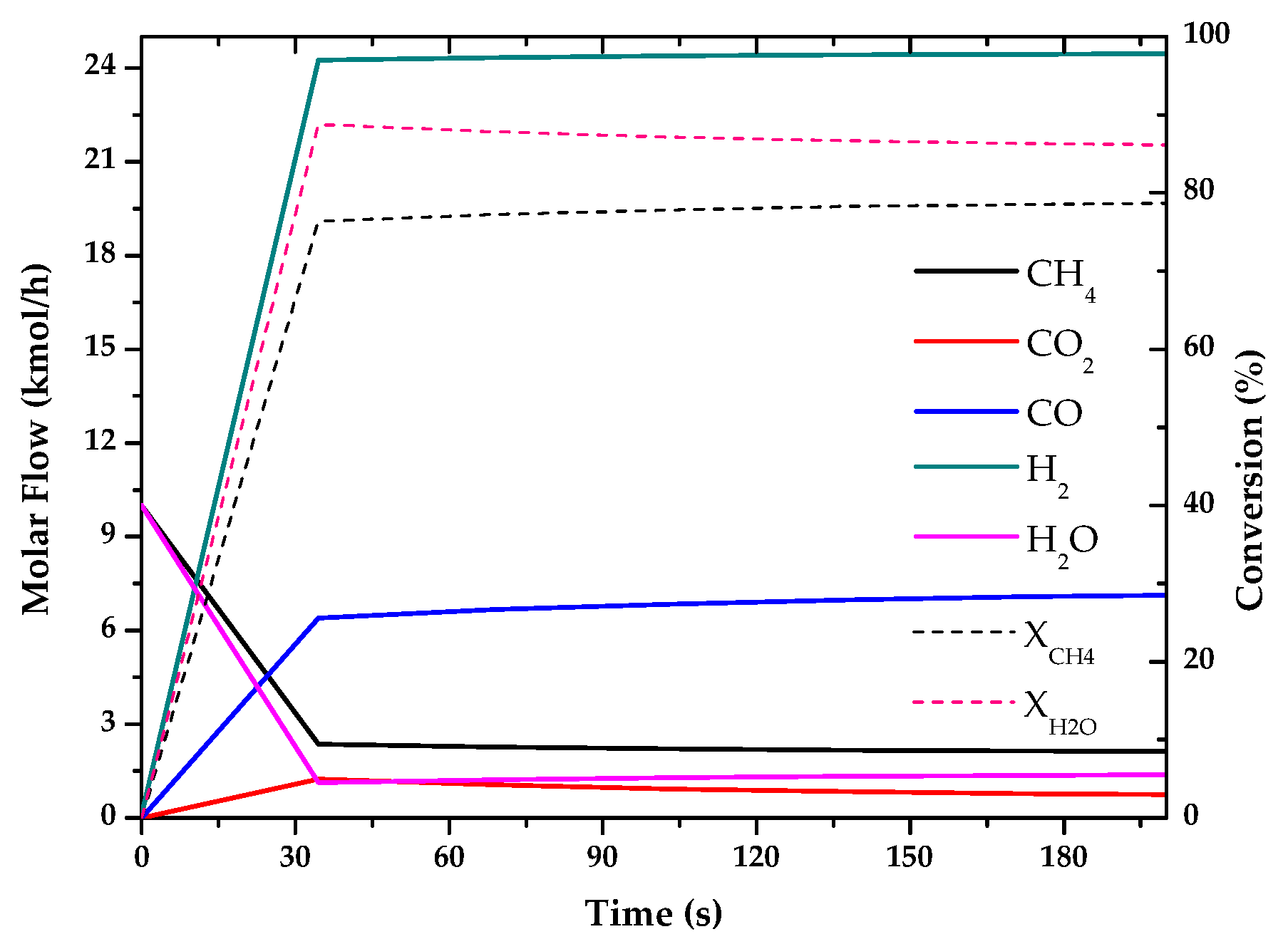
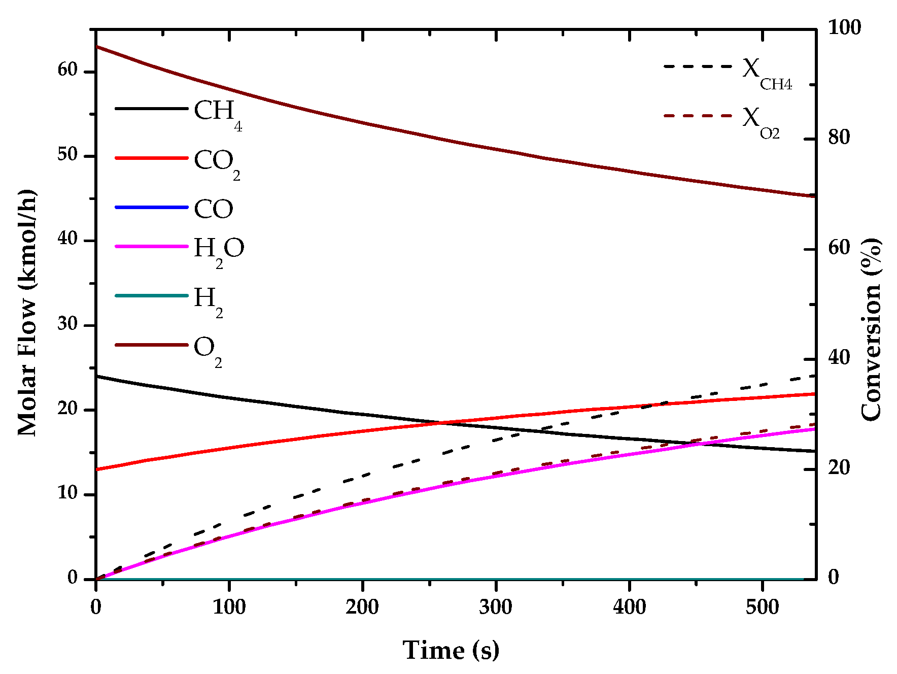
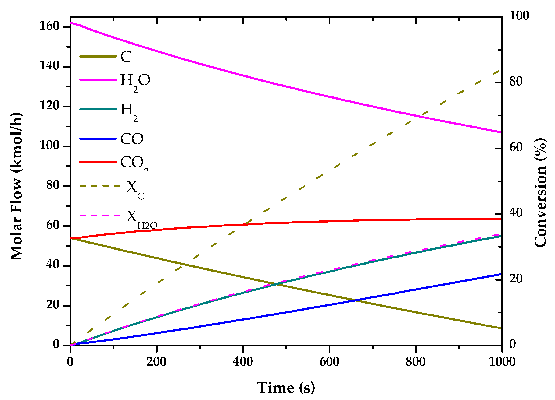
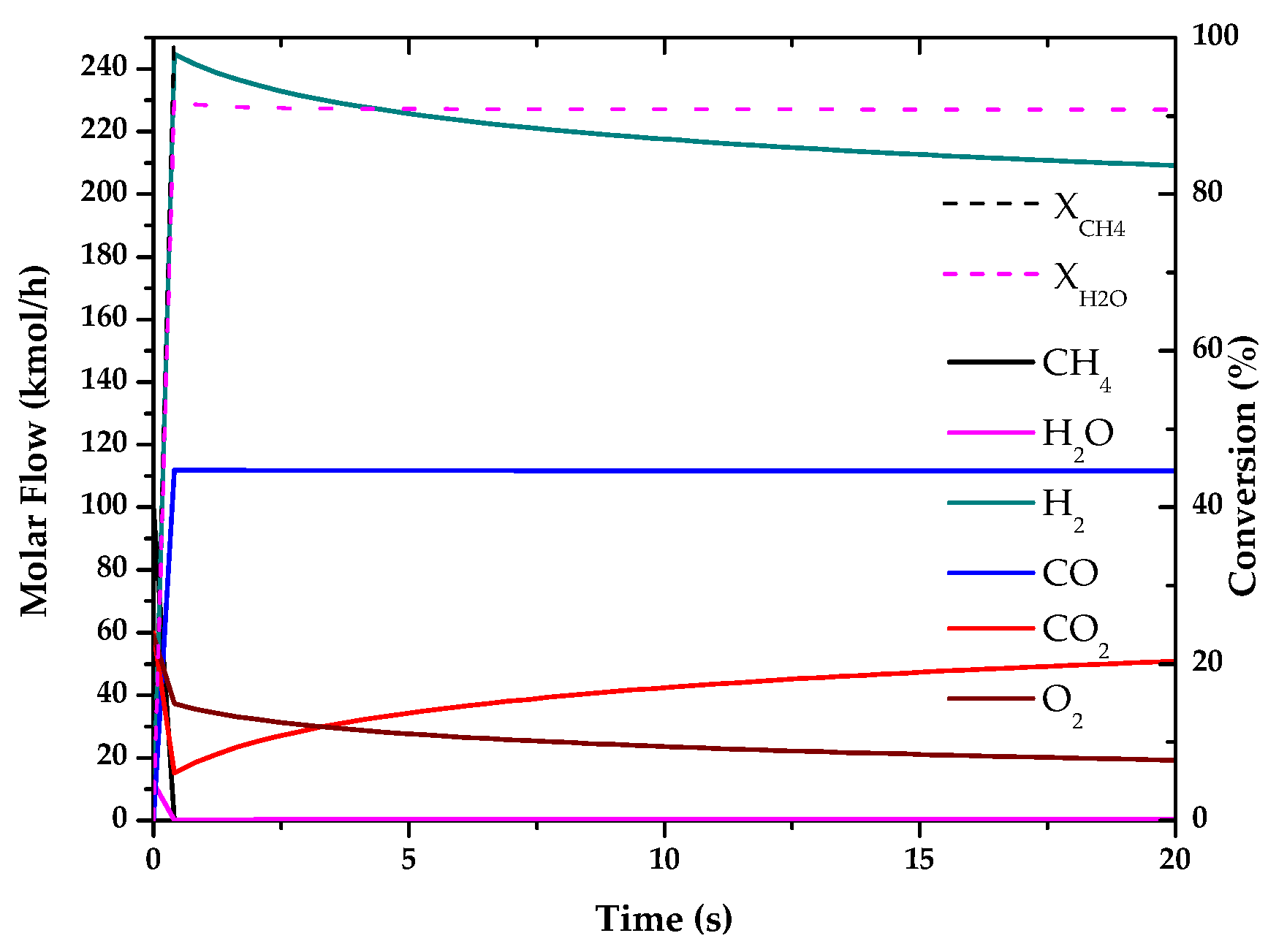
The results of these simulations are shown in the following graphs (Figure 1, Figure 2, Figure 3, Figure 4, Figure 5 and Figure 6). These simulations were carried out taking as operating conditions those described in the corresponding references for knowledge of kinetics.
In Figure 2, Figure 3 and Figure 6, it can be seen that the molar flow profiles deviate considerably at a certain reaction time. This phenomenon is attributed to the fact that the steady state is reached more quickly in these processes. This suggests that the dimensions of the reactor or the reaction time used for the simulation in our software do not match those used in the literature, but these parameters do not affect the subsequent calculations. This profile could be smoothed out by studying a greater number of points in the reaction time in the range where the steady state is reached.
With the simulations of the reactions that are carried out in each reactor, the kinetic constant for the consume of the main fuel for each one of the processes has been determined. In all these cases a simple order one kinetics has been assumed, adjusting the rate of fuel consumed to an exponential using the data analysis software OriginLab [45]. The results of the calculated kinetic parameters with operating conditions are shown in Table 6.
To produce hydrogen through thermochemical methods, a fuel with a hydrocarbon component in a gaseous state is used (except in coal gasification), and accompanied in some cases by other compounds such as CO2 (natural gas), H2O or O2. The products obtained after passing through the reactors are H2 and in some cases also CO, which is also partially converted to H2 through the water-gas exchange reaction (WGS). After these reactions, the products are separated from the rest of the compounds by means of a membrane system or any other separation operation. This separation system is another aspect to study in future investigations, however in this case similar values will be assumed for each process and therefore its influence is not of great importance for this study.
For water electrolysis, only electricity is used as a source of energy, as water cannot be considered as such. Its simulation was different from the rest of the thermochemical methods. This simulation was carried out only by using the DWSIM software with an EXCEL sheet, where an electrical power consumption of 18 kW was prefixed.
Figure 7 shows the simulation scheme for water electrolysis. The electrolysis cell is directly linked to the spreadsheet that simulates its function.
This figure also serves as a sample of the DWSIM software interface, and as an example for the rest of the processes simulated with this software in this study (supplementary materials).

3.2. Energy Analysis

Energy analysis is an important parameter for the viability of a process. Table 7 shows the energy efficiencies of each of the simulated processes. As these efficiencies are defined only by the reactants and products, they correspond essentially to the reactor efficiencies and not to the overall processes. The table compares the simulated results with DWSIM and MATLAB software in relation to the values of different references.
The thermal efficiency has been determined only for the transformation of raw materials into hydrogen and in the overall simulation process, where the energy required by the reactor is considered.
The energy output refers only to the energy of the products (hydrogen and carbon monoxide), and the energy loss includes the rest of the energy used in other process equipment such as pumps, electricity or separators. It should be mentioned that the output currents of the reactor at high temperatures have been used in all processes to heat the input current in a heat exchanger.
In general, the results obtained with the two software are practically identical (<5%), which gives validity to the kinetic models selected for each simulated hydrogen production method. This difference between the results of both software is due to the variation in the calculation method associated with the DWSIM software, but as the value is only 5% at maximum, the result and the software can be accepted as valid for the simulation of these processes, and possibly in new versions of this software the error will be reduced to a minimum.
In the case of water electrolysis, as indicated above, only its simulation was carried out with DWSIM. The comparison of these values with respect to the references is also positive, and the small variations in the values of the thermal efficiencies can be justified by the uncertainty of the complete kinetics used by the authors of these references. In general, the results of the energy efficiencies provide coherence to the simulations as was also observed with the molar flow profiles.
The consideration of the energy applied in the reactor can be estimated that in general in all the processes (except in the partial oxidation of methane, as it is an exothermic process), it reduces the efficiency between 15–30%.
Other parameters that have been calculated from these simulations are energy requirement, CO2 production depending on the production of H2, carbon-hydrogen selectivity and CO2 in relation to the carbon produced (Table 8).
In relation to the energy requirement of the processes, water electrolysis is the one that demands the most energy, about two times more than the second process (DRM). This is due to the greater amount of energy required to break the link of the water molecules than that of the hydrocarbons. In the same way, coal gasification has the lowest value because its fuel does not require breaking links for its reaction.
The rest of the parameters analyzed in Table 8, can be compared with the theoretical data in Table 2. The results show very similar data, except for partial oxidation, because stoichiometric do not consider the energy released by the hydrogen molecule. These results can be compared with those of other studies [46], obtaining data in accordance with ours. All the carbon produced in the processes is CO2, except in the pyrolysis of natural gas and in the dry reforming of methane where solid carbon is also produced.
The results of the energy balance show how the technologies of steam reforming of methane, water electrolysis and partial oxidation of methane, are the most efficient in terms of energy output. However, pyrolysis of natural gas does not produce CO2, unlike all other thermochemical processes and the percentage of energy supplied to the reactor, which can come from renewable sources such as solar energy. Therefore, natural gas pyrolysis is a viable technology from the energy aspect, and really interesting as an alternative for hydrogen production.

3.3. Exergy Analysis

In addition to the energy balance, the exergy analysis of the different processes for the production of hydrogen was also carried out. For this exergy analysis the calculation of the efficiency was realized according to the process described below.
Exergy analysis can be used to improve process design by optimizing resources and operating parameters. Any excess heat in the process can be recovered as thermal or chemical energy, thus increasing the exergetic efficiency of the process [47].
The results of the exergy efficiencies are shown in Table 9, which contains the values obtained from the simulations carried out with the DWSIM software. These efficiencies, as well as the thermal efficiencies, are a function of the products in the reactor and not the overall process. They do not include compressor and pump exergy (low percentages of exergy in). The exergy efficiency is a parameter that is not so often studied as the energy efficiency, so it is complicated to compare it with other references. All percentages have been calculated based on the E x i n .
The results show water electrolysis, autothermal reforming and steam reforming as are the methods with the highest exergy efficiency. In contrast, in methods such as coal gasification or dry reforming of methane, these values are over 1.6 times lower. This difference may be due to the presence of solid carbon in these processes, which contains high amounts of heat that without good optimization is wasted. Additionally, autothermal reforming is an energy self-sustained process, what implies a full utilization of the energy potential of the reactants. Water electrolysis has a high exergetic energy source as electricity with very low exergy destruction.
The natural gas pyrolysis showing lower exergy results than other more currently used processes such as steam reforming of methane. However, methane pyrolysis has the highest percentages of unused exergy, due to the by-product stream (solid carbon). As indicated above, the exergy associated with this parameter ( E x E x h a u s t ) is the only one that can theoretically be recovered, increasing the exergy efficiency of the process to double its value (~80%) [48]. In fact, solid carbon itself is a product that can be efficiently used in the context of the circular economy.
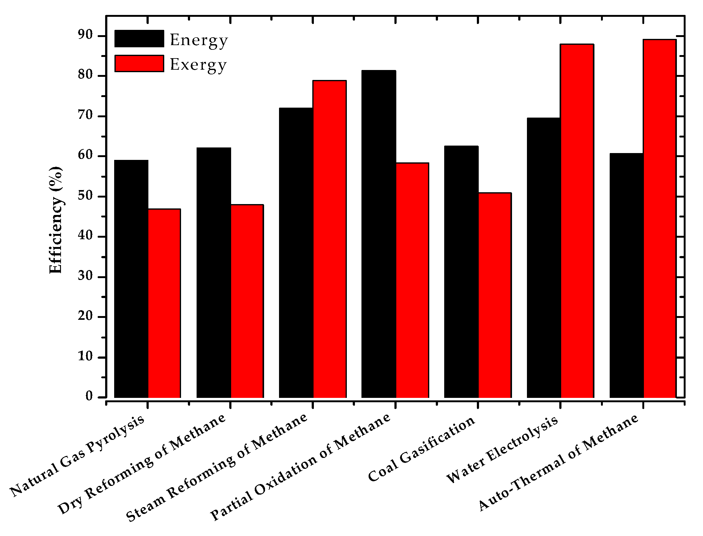
Figure 8 compares the values of energy and exergy efficiencies for the different simulated hydrogen production processes.
In view of the results, water electrolysis, steam reforming and auto-thermal reforming show the highest percentages. This demonstrates the fact that steam reforming and auto-thermal reforming are the most used technologies for hydrogen production at present. In the case of electrolysis, despite of being highly efficient in energy and exergy terms, its high energy demand (25 kWh/kgH2) makes this technology more expensive. However, it is a technology still under study with great expectations for the future.
The pyrolysis of natural gas is another technology with great expectations of study due to the commented possible increase of the exergy efficiency with the use of solid coal produced, and because it does not produce CO2. This means direct environmental benefits and indirect economic benefits, as no additional implementation of carbon capture and sequestration technology is required.

3.4. Carbon Capture and Sequestration/Storage (CCS)

A fundamental stage of the most used processes at industrial level today to produce hydrogen is the addition of CO2 capture and sequestration/storage (CCS) technology. Processes such as methane reforming, partial oxidation or autothermal reforming must be completed with a mechanism to separate and store the CO2 from its output streams, which greatly reduces its energy efficiency as well as increasing its costs.
For the implementation of this type of technology, various parameters must be studied, such as the specification of the quality of the captured carbon dioxide. In the literature, several critical issues in the transport part of carbon capture and storage chain have been identified and covered such as safety and toxicity limits, compression work, hydrate formation, corrosion and free water formation including cross-effects (e.g., hydrogen sulphide and water) [49].
Three technologies exist to capture CO2—pre-combustion, where CO2 is captured before fuel is burned; oxy-fuel, where CO2 is captured during fuel combustion; and post-combustion, where CO2 is captured after fuel has been burned (this technology can be retrofitted to existing power and industrial plants) [50].
This article did not study the different technologies or the characteristics of the CO2 streams, leaving it as a possible future research. However, assuming the implementation of post-combustion technology, which is the most employed in the industry, we know from previous studies that it carries a penalty of between 20–30% of energy efficiency. To make a more global comparison, a 25% energy efficiency penalty has been applied to all processes studied where additional implementation of carbon capture and sequestration is required. Table 10 shows the results with and without CCS technology.
The implementation of CCS means that technologies such as carbon gasification and dry reforming of methane are penalized in their overall energy efficiency. However, natural gas pyrolysis and electrolysis would increase their competiveness respect to mature technologies such as steam reforming, autothermal reforming and partial oxidation. Reducing the energy penalty associated with CO2 capture is one of the key issues of CCS technologies. The efficiency of carbon capture must be improved to reduce the energy penalty because the capture stage is the most energy-consuming stage in the entire process of CCS [31].

4. Conclusions

We have made an analysis of the most promising hydrogen production methods. Natural gas steam reforming is the preferred technology in many ambitious hydrogen deployment projects. Among the available fossil fuel based methods at an industrial scale, steam reforming shows the lower CO2 production per hydrogen product at a reasonable hydrogen cost. Nowadays, that is the preferred option in combination with carbon capture and sequestration (CCS) for high scale projects. In opposition, water electrolysis is a CO2-free method for hydrogen production, providing that clean electricity is used. Nevertheless, energy requirements for hydrolysis is 4 times higher than steam reforming, which implies a much more energy intensive processes with a strong dependency of the regulation and costs of the renewable electricity market and much more stress on the capacity of renewable energy facilities.
From the exergy analysis, dry reforming of methane and coal gasification, even if they are mature processes, show a lower efficiency. In particular coal gasification has higher CO2 production, which implies that in spite of the economic aspects, it is handicapped in its application to the energy transition towards a more sustainable system. The implementation of additional CCS techniques in the current state of the art would make coal gasification uncompetitive in the long term. Dry reforming is a process that shows a similar net CO2 emission as steam reforming, with the ability of reducing CO2 to CO at some point in the process, which could increase its interest in the context of the circular economy.
Our analysis is referred to as the basic reactor and associated process. The impact on the energy efficiency of the overall integration of hydrogen production technologies with a significant production of CO2 should be complemented with the consideration of CCS for their implementation into a sustainable future. In that sense, electrolysis and natural gas pyrolysis will not be strongly affected. There are other issues that should be analysed for the complete picture, as induced emissions by natural gas leakage, or life cycle of electrolyser components. Nevertheless, these technologies have to face the challenge of being able to achieve very high capacity of hydrogen production. In particular, natural gas pyrolysis must advance on its development. The production of carbon as main by-product and its full integration in the circular economy would increase the interest of methane pyrolysis as it will require much less energy than electrolysis with the additional outcome of a useful material for further processing (C).

Supplementary Materials

The following are available online at https://www.mdpi.com/1099-4300/22/11/1286/s1, Figure S1: Simulation for Natural Gas Pyrolysis in DWSIM, Figure S2: Simulation for Dry Reforming of Methane in DWSIM, Figure S3: Simulation for Steam Reforming of Methane in DWSIM, Figure S4: Simulation for Partial Oxidation of Methane in DWSIM, Figure S5: Simulation for Water Electrolysis in DWSIM, Figure S6: Simulation for Coal Gasification in DWSIM, Figure S7: Simulation for Auto-thermal Reforming of Methane in DWSIM, Table S1: Thermodynamic and rate constants.

Author Contributions

Conceptualization, A.A.; Investigation, A.M.-R.; Methodology, A.A.; Software, A.M.-R.; Supervision, A.A.; Writing—original draft, A.M.-R. and A.A.; Writing—review & editing, A.A. All authors have read and agreed to the published version of the manuscript.

Funding

The authors wish to thank to “Comunidad de Madrid” and European Structural Funds for their financial support to ACES2030-CMproject(S2018/EMT-4319).

Conflicts of Interest

The authors declare no conflict of interest.

Nomenclature

η E n e r g y Energy efficiency, %
m i Mass flow, kg s−1
L H V Lower heating value, MJ kg−1
Q H e a t Heat of reaction, MJ s−1
η E x e r g y Exergy efficiency, %
E x i Exergy, kJ mol−1
P Pressure, bar
T Temperature, K
k Kinetic constant, s−1
F C H 4 0 Initial molar flow fuel, kmol h−1

Abbreviations

GHGGreenhouse Gas
IPCCIntergovernmental Panel on Climate Change
NGPNatural Gas Pyrolysis
DRMDry Reforming of Methane
SMRSteam Reforming of Methane
POMPartial Oxidation of Methane
CGCoal Gasification
ATMAuto-thermal Reforming of Methane
WEWater Electrolysis
WGSWater-Gas Shift
PrOxPreferential Oxidation
RWGSReverse Water-Gas Shift
LHVLower Heating Value
CCSCarbon Capture and Sequestration

References

  1. Birol, F.; Cozzi, L.; Bromhead, A.; Gould, T.; Baroni, M. World Energy Outlook 2014; International Energy Agency: Paris, France, 2014; p. 726. [Google Scholar]
  2. International Energy Agency. World Energy Outlook Special Report; International Energy Agency: Paris, France, 2015. [Google Scholar]
  3. Stocker, T.F.; Qin, D.; Plattner, G.K.; Tignor, M.M.B.; Allen, S.K.; Boschung, J.; Nauels, A.; Xia, Y.; Bex, V.; Midgley, P.M. Climate change 2013 the physical science basis: Working Group I contribution to the fifth assessment report of the intergovernmental panel on climate change. Clim. Chang. 2013 Phys. Sci. Basis Work. Gr. I Contrib. Fifth Assess. Rep. Intergov Panel Clim. Chang. 2013, 9781107057, 1–1535. [Google Scholar]
  4. Marbán, G.; Valdés-Solís, T. Towards the Hydrogen Economy? Int. J. Hydrogen Energy 2007, 32, 1625–1637. [Google Scholar] [CrossRef] [Green Version]
  5. Samanta, S.K.; Verma, P. Advanced Hydrogen Production through Methane. Discov. J. 2015, 1, 109–123. [Google Scholar]
  6. Liu, B.; Liu, S.; Guo, S.; Zhang, S. Economic study of a large-scale renewable hydrogen application utilizing surplus renewable energy and natural gas pipeline transportation in China. Int. J. Hydrogen Energy 2020, 45, 1385–1398. [Google Scholar] [CrossRef]
  7. Bellocchi, S.; De Falco, M.; Gambini, M.; Manno, M.; Stilo, T.; Vellini, M. Opportunities for power-to-Gas and Power-to-liquid in CO2-reduced energy scenarios: The Italian case. Energy 2019, 175, 847–861. [Google Scholar] [CrossRef]
  8. Götz, M.; Lefebvre, J.; Mörs, F.; McDaniel Koch, A.; Graf, F.; Bajohr, S.; Reimert, R.; Kolb, T. Renewable Power-to-Gas: A technological and economic review. Renew. Energy 2016, 85, 1371–1390. [Google Scholar] [CrossRef] [Green Version]
  9. ADEME. Technical Review: The Role of Hydrogen in the Energy Transition; ADEME: Angers, France, 2018; Volume 2018. [Google Scholar]
  10. Boudries, R.; Dizène, R.; Khellaf, A.; Belhamel, M. Hydrogen as an energy carrier. In Clean Energy: Resources, Production and Developments; Nova Science Publishers, Inc.: Hauppauge, NY, USA, 2012; pp. 147–184. ISBN 9781617615092. [Google Scholar]
  11. Stolten, D.; Emonts, B. Hydrogen Science and Engineering: Materials, Processes, Systems and Technology; Wiley-VCH Verlag: Weinheim, Germany, 2016; Volume 1–2, ISBN 9783527674268. [Google Scholar]
  12. Nazir, S.M.; Cloete, J.H.; Cloete, S.; Amini, S. Efficient hydrogen production with CO2 capture using gas switching reforming. Energy 2019, 185, 372–385. [Google Scholar] [CrossRef]
  13. Ogden, J.M. Prospects for building a hydrogen energy infrastructure. Annu. Rev. Energy Environ. 1999, 24, 227–279. [Google Scholar] [CrossRef]
  14. Kalamaras, C.M.; Efstathiou, A.M. Hydrogen Production Technologies: Current State and Future Developments. Conf. Pap. Energy 2013, 2013, 1–9. [Google Scholar] [CrossRef] [Green Version]
  15. Stadler, P.; Caliandro, P.; Leonardi, C.; Van Herle, J. Cost Evaluation of Large Scale Hydrogen Production for the Aviation Industry; Master Semester Project; École Polytechnique Fédérale de Lausanne: Lausanne, Switzerland, 2014. [Google Scholar]
  16. Dincer, I.; Acar, C. Review and evaluation of hydrogen production methods for better sustainability. Int. J. Hydrogen Energy 2014, 40, 11094–11111. [Google Scholar] [CrossRef]
  17. El-Shafie, M.; Kambara, S.; Hayakawa, Y. Hydrogen Production Technologies Overview. J. Power Energy Eng. 2019, 7, 107–154. [Google Scholar] [CrossRef] [Green Version]
  18. Bhat, S.A.; Sadhukhan, J. Process intensification aspects for steam methane reforming: An overview. AIChE J. 2009, 55, 408–422. [Google Scholar] [CrossRef]
  19. Maqbool, W.; Park, S.J.; Lee, E.S. Steam methane reforming of natural gas with substantial carbon dioxide contents—Process optimization for gas-to-liquid applications. In Proceedings of the Applied Mechanics and Materials; Trans Tech Publications: Stafa-Zurich, Switzerland, 2014; Volume 548–549, pp. 316–320. [Google Scholar]
  20. Corbo, P.; Migliardini, F. Hydrogen production by catalytic partial oxidation of methane and propane on Ni and Pt catalysts. Int. J. Hydrogen Energy 2007, 32, 55–66. [Google Scholar] [CrossRef]
  21. Lin, S.; Harada, M.; Suzuki, Y.; Hatano, H. Hydrogen production from coal by separating carbon dioxide during gasification. Fuel 2002, 81, 2079–2085. [Google Scholar] [CrossRef]
  22. De Castro, J.; Rivera-Tinoco, R.; Bouallou, C. Hydrogen production from natural gas: Auto-Thermal Reforming and CO2 capture. In Proceedings of the Chemical Engineering Transactions; Italian Association of Chemical Engineering—AIDIC: Milano, Italy, 2010; Volume 21, pp. 163–168. [Google Scholar]
  23. Shiva Kumar, S.; Himabindu, V. Hydrogen production by PEM water electrolysis—A review. Mater. Sci. Energy Technol. 2019, 2, 442–454. [Google Scholar] [CrossRef]
  24. Guéret, C.; Daroux, M.; Billaud, F. Methane pyrolysis: Thermodynamics. Chem. Eng. Sci. 1997, 52, 815–827. [Google Scholar] [CrossRef]
  25. Buelens, L.C.; Galvita, V.V.; Poelman, H.; Detavernier, C.; Marin, G.B. Super-dry reforming of methane intensifies CO2 utilization via le Chatelier’s principle. Science 2016, 354, 449–452. [Google Scholar] [CrossRef]
  26. Summa, P.; Samojeden, B.; Motak, M. Dry and steam reforming of methane. Comparison and analysis of recently investigated catalytic materials. A short review. Polish J. Chem. Technol. 2019, 21, 31–37. [Google Scholar] [CrossRef]
  27. Holladay, J.D.; Hu, J.; King, D.L.; Wang, Y. An overview of hydrogen production technologies. Catal. Today 2009, 139, 244–260. [Google Scholar] [CrossRef]
  28. Nikolaidis, P.; Poullikkas, A. A comparative overview of hydrogen production processes. Renew. Sustain. Energy Rev. 2017, 67, 597–611. [Google Scholar] [CrossRef]
  29. Xu, L.; Wang, Y.; Shah, S.A.A.; Zameer, H.; Solangi, Y.A.; Walasai, G.D.; Siyal, Z.A. Economic Viability and Environmental Efficiency Analysis of Hydrogen Production Processes for the Decarbonization of Energy Systems. Processes 2019, 7, 494. [Google Scholar] [CrossRef] [Green Version]
  30. Ni, M.; Leung, M.K.H.; Leung, D.Y.C. Energy and exergy analysis of hydrogen production by a proton exchange membrane (PEM) electrolyzer plant. Energy Convers. Manag. 2008, 49, 2748–2756. [Google Scholar] [CrossRef]
  31. Kurokawa, H.; Shirasaki, Y.; Yasuda, I. Energy-efficient distributed carbon capture in hydrogen production from natural gas. In Proceedings of the Energy Procedia; Elsevier Ltd.: Amsterdam, The Netherlands, 2011; Volume 4, pp. 674–680. [Google Scholar]
  32. F-Chart-Software EES: Engineering Equation Solver | F-Chart Software: Engineering Software. Available online: http://www.fchart.com/ees/ees-refprop.php (accessed on 3 November 2020).
  33. Chein, R.Y.; Hsu, W.H. Analysis of syngas production from biogas via the tri-reforming process. Energies 2018, 11, 1075. [Google Scholar] [CrossRef] [Green Version]
  34. Wang, Z.; Fan, W.; Zhang, G. Comparison of the exergy efficiency of four power generation systems from methane using fuel cells. RSC Adv. 2017, 7, 39391–39402. [Google Scholar] [CrossRef] [Green Version]
  35. Simpson, A.P.; Lutz, A.E. Exergy analysis of hydrogen production via steam methane reforming. Int. J. Hydrogen Energy 2007, 32, 4811–4820. [Google Scholar] [CrossRef]
  36. Modeiros, D. DWSIM Open Source Process Simulator. Available online: http://dwsim.inforside.com.br/wiki/index.php?title=DWSIM (accessed on 24 March 2020).
  37. Benguerba, Y.; Virginie, M.; Dumas, C.; Ernst, B. Methane dry reforming over Ni-Co/Al2O3: Kinetic modelling in a catalytic fixed-bed reactor. Int. J. Chem. React. Eng. 2017, 15, 15. [Google Scholar] [CrossRef]
  38. Keith, J.M. Hydrogen Education Curriculum Path at Michigan Technological University; MichiganTech: Houghton, MI, USA, 2010. [Google Scholar]
  39. Hoang, D.L.; Chan, S.H.; Ding, O.L. Kinetic modelling of partial oxidation of methane in an oxygen permeable membrane reactor. Chem. Eng. Res. Des. 2005, 83, 177–186. [Google Scholar] [CrossRef]
  40. Fernandes, F.A.N.; Sousa, J.F.; Souza, C.P.; Rodrigues, S. Modeling of Partial Oxidation of Methane in a Membrane Reactor. Rev. Eng. Térmica 2018, 5, 40–45. [Google Scholar] [CrossRef]
  41. Zeng, K.; Zhang, D. Recent progress in alkaline water electrolysis for hydrogen production and applications. Prog. Energy Combust. Sci. 2009, 36, 307–326. [Google Scholar] [CrossRef]
  42. Solli, K.-A.; Kumar Thapa, R.; Moldestad, B.M.E. Screening of Kinetic Rate Equations for Gasification Simulation Models. In Proceedings of the 9th EUROSIM Congress on Modelling and Simulation, EUROSIM 2016, 57th SIMS Conf. Simul. Model. SIMS 2016, Oulu, Finland, 12–16 September 2016; Volume 142, pp. 105–112. [Google Scholar]
  43. Umeki, K.; Yamamoto, K.; Namioka, T.; Yoshikawa, K. High temperature steam-only gasification of woody biomass. Appl. Energy 2010, 87, 791–798. [Google Scholar] [CrossRef]
  44. Zahedi nezhad, M.; Rowshanzamir, S.; Eikani, M.H. Autothermal reforming of methane to synthesis gas: Modeling and simulation. Int. J. Hydrogen Energy 2009, 34, 1292–1300. [Google Scholar] [CrossRef]
  45. OriginLab—Origin and OriginPro—Data Analysis and Graphing Software. Available online: http://www.originlab.com/ (accessed on 29 April 2020).
  46. Abánades, A.; Rubbia, C.; Salmieri, D. Thermal cracking of methane into Hydrogen for a CO2-free utilization of natural gas. Int. J. Hydrogen Energy 2013, 38, 8491–8496. [Google Scholar] [CrossRef]
  47. Thengane, S.K.; Hoadley, A.; Bhattacharya, S.; Mitra, S.; Bandyopadhyay, S. Exergy efficiency improvement in hydrogen production process by recovery of chemical energy versus thermal energy. Clean Technol. Environ. Policy 2016, 18, 1391–1404. [Google Scholar] [CrossRef]
  48. Wang, Z.; Fan, W.; Zhang, G.; Dong, S. Exergy analysis of methane cracking thermally coupled with chemical looping combustion for hydrogen production. Appl. Energy 2016, 168, 1–12. [Google Scholar] [CrossRef]
  49. Cormos, C.C. Hydrogen production from fossil fuels with carbon capture and storage based on chemical looping systems. Int. J. Hydrogen Energy 2011, 36, 5960–5971. [Google Scholar] [CrossRef]
  50. Kocs, E.A. The global carbon nation: Status of CO2 capture, storage and utilization. EPJ Web Conf. 2017, 148, 00002. [Google Scholar] [CrossRef] [Green Version]
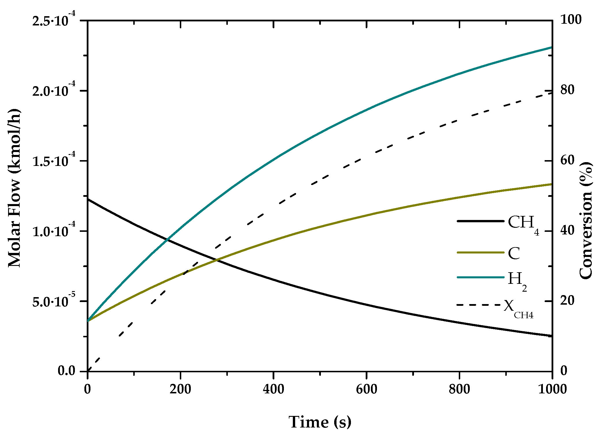
Figure 1. Evolution of molar flow profiles over time for Natural Gas Pyrolysis (T = 1173 K; P = 1 bar).
Entropy 22 01286 g001
Figure 2. Evolution of molar flow profiles over time for Dry Reforming of Methane (T = 973 K; P = 1 bar).
Entropy 22 01286 g002
Figure 3. Evolution of molar flow profiles over time for Steam Reforming of Methane (T = 1000 K; P = 1 bar).
Entropy 22 01286 g003
Figure 4. Evolution of molar flow profiles over time for Partial Oxidation of Methane (T = 1223 K; P = 1 bar).
Entropy 22 01286 g004
Figure 5. Evolution of molar flow profiles over time for Coal Gasification (T = 1123 K; P = 1 bar).
Entropy 22 01286 g005
Figure 6. Evolution of molar flow profiles over time for Autothermal Reforming of Methane (T = 1510 K; P = 21 bar). The figures show the final molar flow results for each component involved in the reactions and fuel conversion, both as a function of the residence time to equilibrium, or to a fixed time known by the reference used for its simulation.
Entropy 22 01286 g006
Figure 7. Simulation scheme for water electrolysis in DWSIM.
Entropy 22 01286 g007
Figure 8. Comparison between energy and exergy efficiencies.
Entropy 22 01286 g008
Table 1. Overview of hydrogen production methods by primary energy and material source [16].
MethodSourceBrief Description
Primary EnergyMaterial
ElectrolysisElectricalWaterDirect current is used to split water into O2 and H2 (electrochemical reaction)
Plasma arc decompositionFossil fuelsCleaned natural gas is passed through plasma arc to generate H2 and carbon soot
ThermolysisThermalWaterThermal decomposition of water (steam) at temperatures over 2500 K
Thermochemical (Water splitting)WaterCyclical chemical reactions (net reaction: water splitting into H2)
Thermochemical (Biomass conversion)BiomassThermocatalytic conversion
Thermochemical (Gasification)Conversion of biomass into syngas
Thermochemical (Reforming)Conversion of liquid biomass (biofuels) into H2
PV electrolysisPhotonicWaterPV panels are used to generate electricity
PhotocatalysisWater is split into H2 by using the electron-hole pair generated by the photocatalyst
Photoelectrochemical methodA hybrid cell simultaneously produces current and voltage upon absorption of light
Dark fermentationBiochemicalBiomassBiological systems are used to generate H2 in the absence of light
High temperature electrolysisElectrical + ThermalWaterElectrical and thermal energy are used together to drive water splitting at high temperatures
Coal gasificationConversion of coal into syngas
Fossil fuel reformingFossil fuels are converted to H2 and CO2
BiophotolysisPhotonic + BiochemicalBiomass + WaterBiological systems (microbes, bacteria, etc.) are used to generate H2
PhotofermentationFermentation process activated by exposure to light
PhotoelectrolysisElectrical + PhotonicWaterPhotoelectrodes and external electricity are used to drive water electrolysis
Table 2. Hydrogen production methods and stoichiometric parameters 1.
Global Reaction m o l   C O 2 m o l   H 2 m o l   C m o l   H 2 m o l   C O 2 m o l   C
Natural Gas Pyrolysis C H 4   C + 2 H 2 -0.50
Dry Reforming of Methane 2 C H 4 + C O 2 + 2 H 2 O 2 C O 2 + 6 H 2 + C 0.330.500.5
Steam Reforming of Methane C H 4 + 2 H 2 O 4 H 2 + C O 2 0.250.251
Partial Oxidation of Methane 3 C H 4 + 2 O 2 + 2 H 2 O 3 C O 2 + 8 H 2 0.380.381
Coal Gasification 2 C + 4 H 2 O + C O 2 4 H 2 + 3 C O 2 0.750.751
Water Electrolysis H 2 O H 2 + 0.5 O 2 ---
Autothermal Reforming of Methane 3 C H 4 + 2 O 2 + 2 H 2 O 8 H 2 + 3 C O 2 0.380.381
1 CO Syngas is assumed to produce CO2 by water shift reaction. In the case of dry reforming, the CO2 produced is the net balance, as CO2 is an input to the process.
Table 3. Advantages and disadvantages of hydrogen production technologies (modified from [27] and [5]).
TechnologyAdvantagesDisadvantages
Natural Gas PyrolysisNo emission CO2 and CO
Oxygen and water not required
Fuel flexibility
Carbon formed
High operating temperatures
Reforming of MethaneMost extensive industrial experience
Oxygen not required
Lowest process temperature
Best H2/CO ratio for H2 production
Highest air emissions
Partial Oxidation of MethaneReduced desulfurization requirement
No catalyst requirement
Low methane slip
Low H2/CO ratio
High operating temperatures
Complex handling process
Coal GasificationRemove impurities before burning the fuel
Lower material costs
High coal demands
High CO2 production/H2
ElectrolysisNo emission CO2
Production of high purity hydrogen
High energy requirement
Autothermal Reforming of MethaneLower process temperature than partial oxidation
Low methane slip
Limited commercial experience
Air/oxygen requirement
Table 4. Low heat value ( L H V ) of pure substances 2 [32].
Substance
L H V   ( MJ / kg )
CH451.12
CO2-
H2120.00
CO10.10
H2O-
C (s)32.80
O2-
2 Pressure 1 atm, Temperature 20 °C.
Table 5. Standard mole chemical exergy of pure substances [34].
Substance E x c h   ( kJ / mol )
CH4831.65
CO219.87
H2236.10
CO275.10
H2O9.50
C (s)410.00
O23.87
Table 6. Rate constants of fuel consumption in thermochemical processes under reference conditions.
Temperature (K)Pressure (bar) k   ( s 1 ) F C H 4 0 ( k m o l / h )  
Natural Gas Pyrolysis11731−1.58·10−31.23·10−4
Dry Reforming of Methane9731−1.68·1046.18·10−5
Steam Reforming of Methane10001−0.107.90
Partial Oxidation of Methane12231−2.10·10−312.94
Coal Gasification11231−2.77·10−4187.82
Autothermal Reforming of Methane151021−53.21100.00
Table 7. Energy efficiencies for hydrogen production reactors.
Energy Efficiency (%)
in Transformation
DWSIM
in Transformation
MATLAB
Reference
[5,13,14,46]
Process
DWSIM
Natural Gas Pyrolysis58.9955.19~55–5844.95
Dry Reforming of Methane62.1362.32~56–8540.85
Steam Reforming of Methane71.9871.66~7464.95
Partial Oxidation of Methane81.2781.47~70–8078.39
Coal Gasification62.4962.13~6051.75
Electrolysis69.46-~50–7047.64
Autothermal Reforming of Methane60.6661.38−60–7556.85
Table 8. Energy requirement and CO2 production for hydrogen production reactors.
Energy Requirement
(kWh/kg H2)
m o l   C O 2 m o l   H 2 m o l   C m o l   H 2 m o l   C O 2 m o l   C
Natural Gas Pyrolysis16.28-0.5-
Dry Reforming of Methane24.500.340.540.47
Steam Reforming of Methane10.840.320.321.00
Partial Oxidation of Methane 2-4.484.481.00
Coal Gasification3.760.770.771.00
Electrolysis47.99---
Autothermal Reforming of Methane5.760.310.311.00
2 CO2 production as a function of H2 and energy produced.
Table 9. Exergy efficiencies simulated for hydrogen production reactors.
η e x e r g y   ( % ) E x D e s t r u c t i o n ( % ) E x E x h a u s t ( % ) E x u n u s e d ( % )
Natural Gas Pyrolysis46.8853.1240.7093.82
Dry Reforming of Methane47.9752.031.4653.50
Steam Reforming of Methane78.8721.130.2621.39
Partial Oxidation of Methane58.3541.655.5147.16
Coal Gasification50.9249.086.4555.55
Electrolysis87.9212.080.7312.81
Autothermal Reforming of Methane89.0810.920.7511.66
Table 10. Exergy efficiencies with and without CCS technology for hydrogen production reactors.
Energy Efficiency (%)
in Transformation With CCS
Natural Gas Pyrolysis58.9958.99
Dry Reforming of Methane62.1346.60
Steam Reforming of Methane71.9853.99
Partial Oxidation of Methane81.2760.95
Coal Gasification62.4946.87
Electrolysis69.4669.46
Autothermal Reforming of Methane60.6645.50
Publisher’s Note: MDPI stays neutral with regard to jurisdictional claims in published maps and institutional affiliations.