Exergy Analysis of Fluidized Desiccant Cooling System


Abstract
1. Introduction
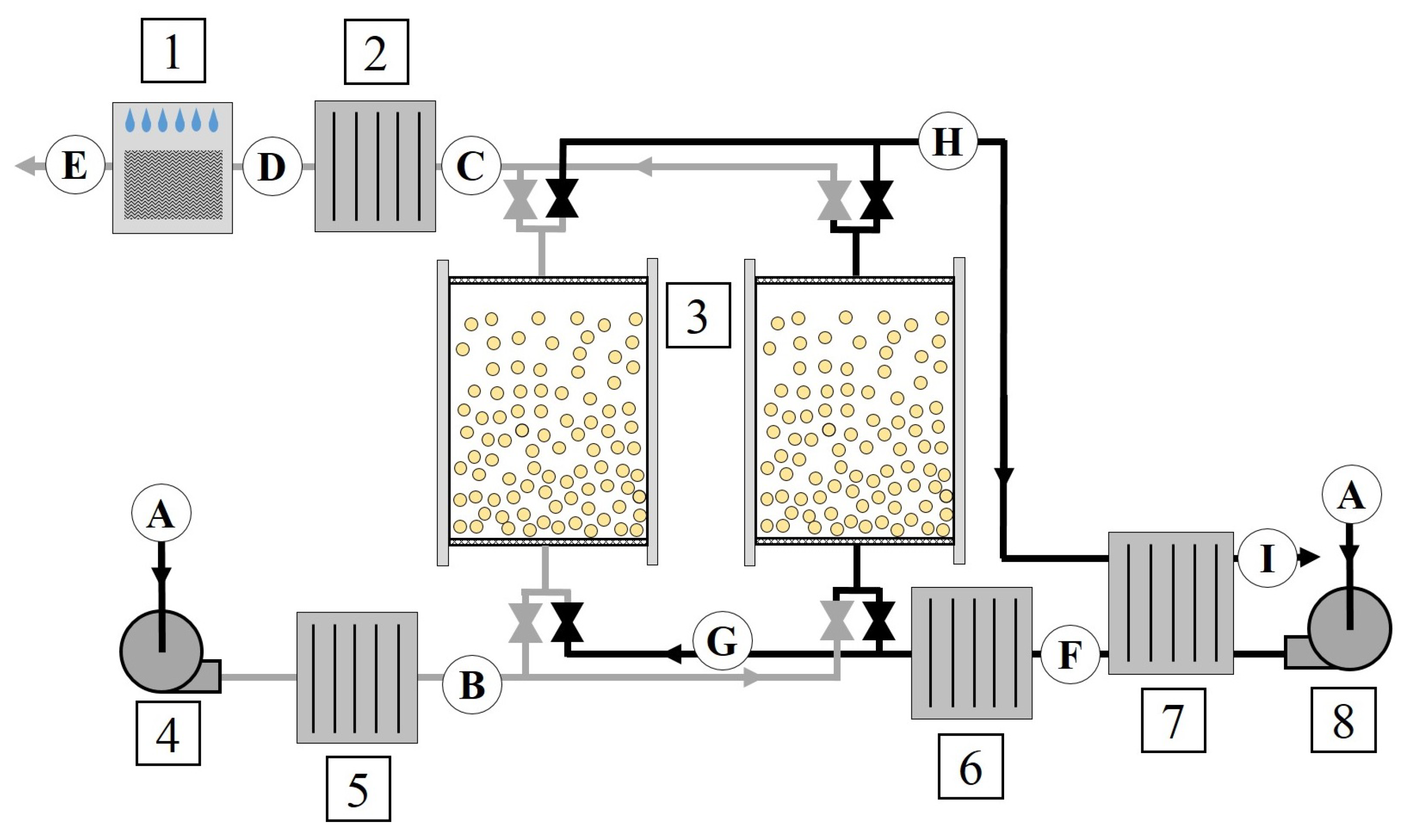
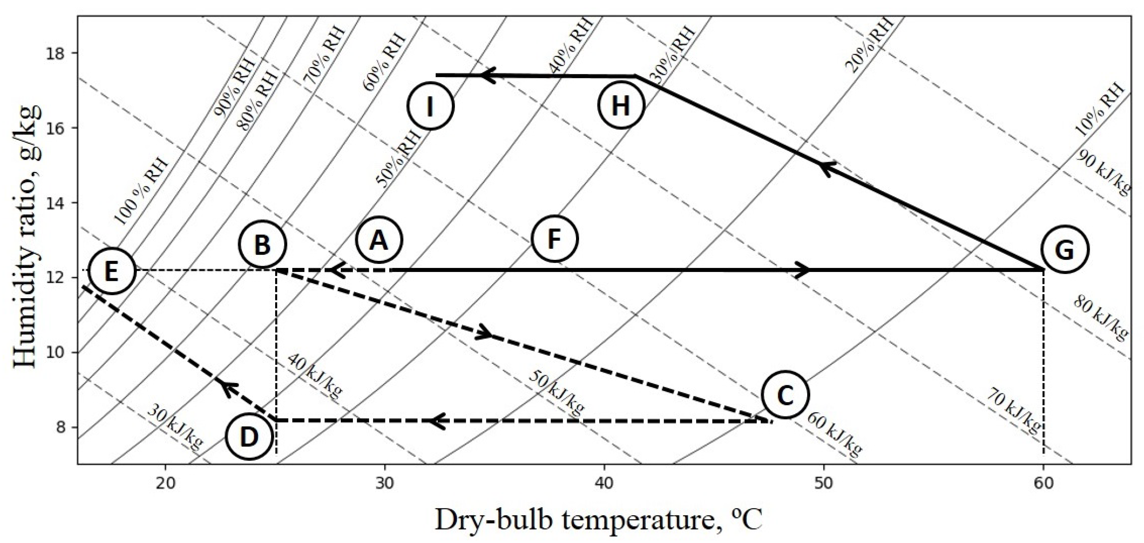
2. Fluidized Desiccant Cooling System
3. Exergy Analysis
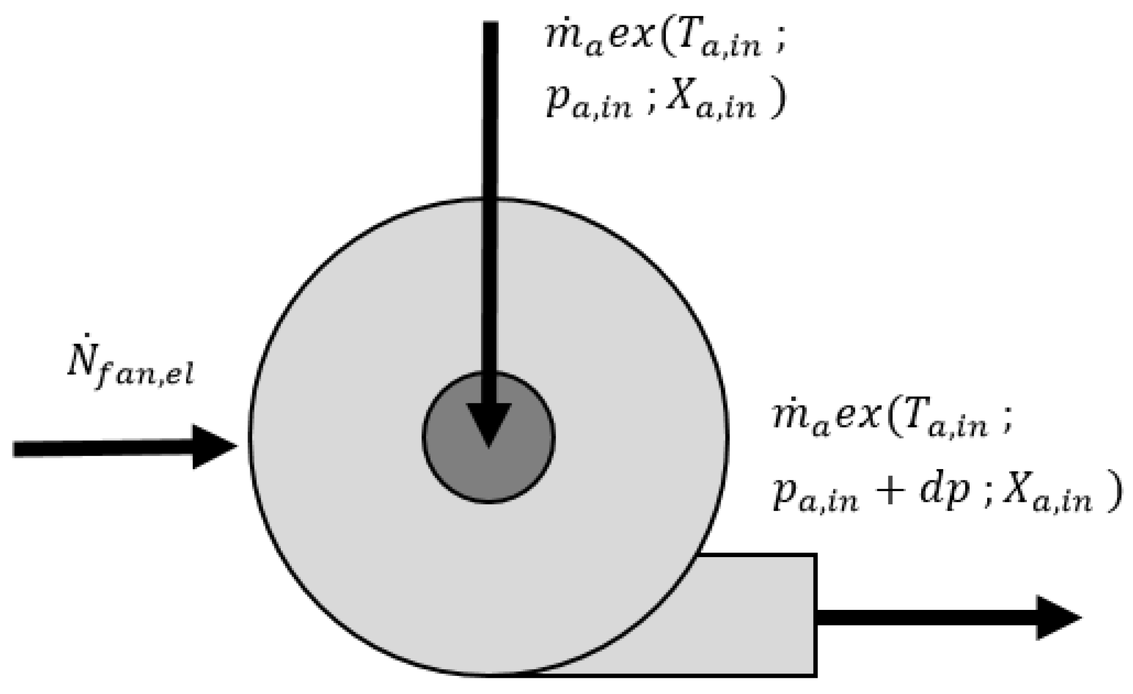
3.1. Electric Fans
- The electric fan has an isentropic efficiency of 70% (such efficiency was justified by [19]).
- The increase of the exergy of the air compressed in the electric fan is only due to the pressure rise (the temperature-related exergy is neglected).
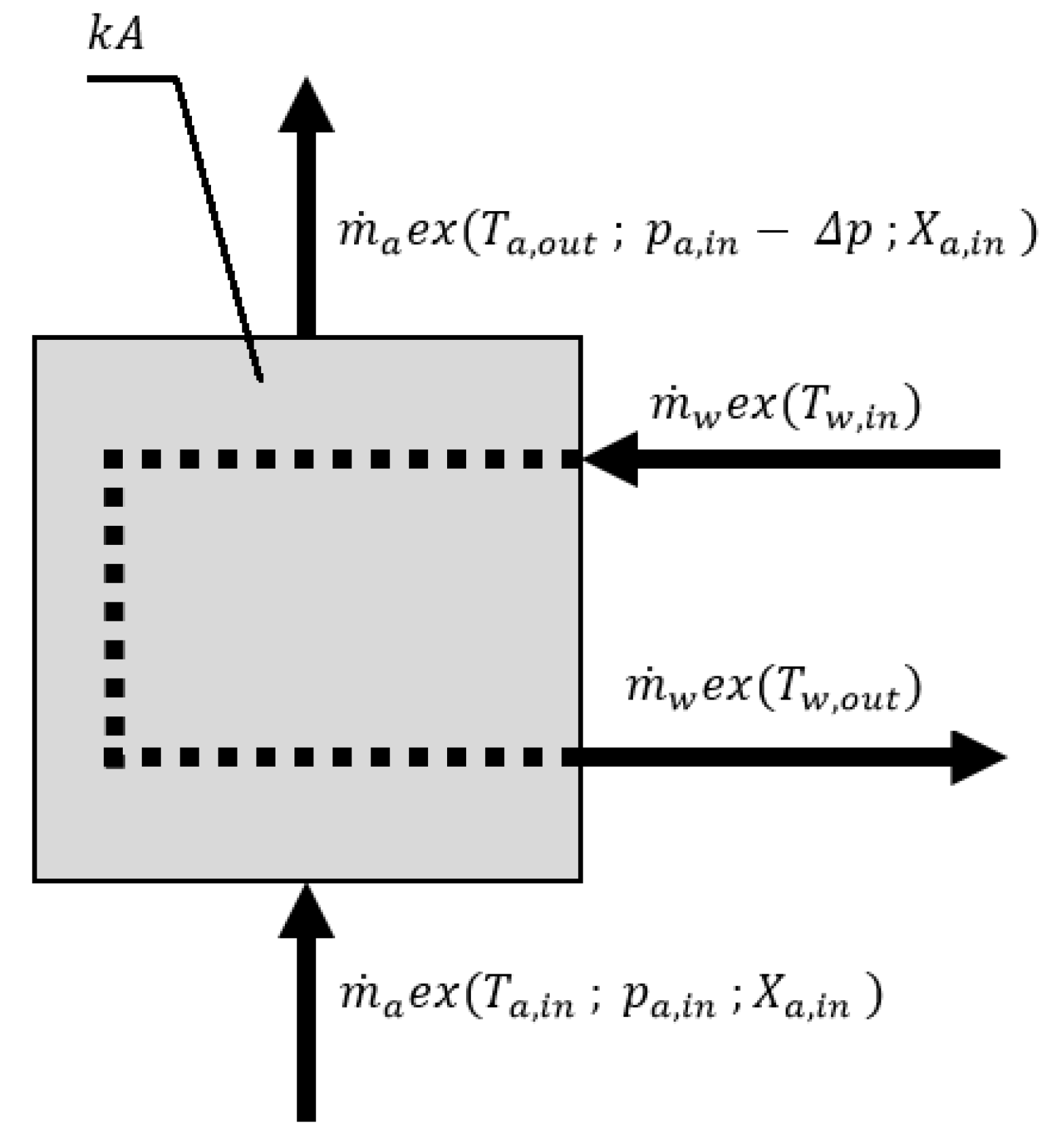
3.2. Air Heater/Cooler
- The outer wall of the heat exchanger is adiabatic,
- The heat capacity of the heat exchanger is negligible,
- The water pressure drop in the heat exchanger is negligible,
- Condensation of water vapor on the heat exchange surfaces does not occur,
- In the case of the air cooler, the exergy of water at the outlet is dissipated.
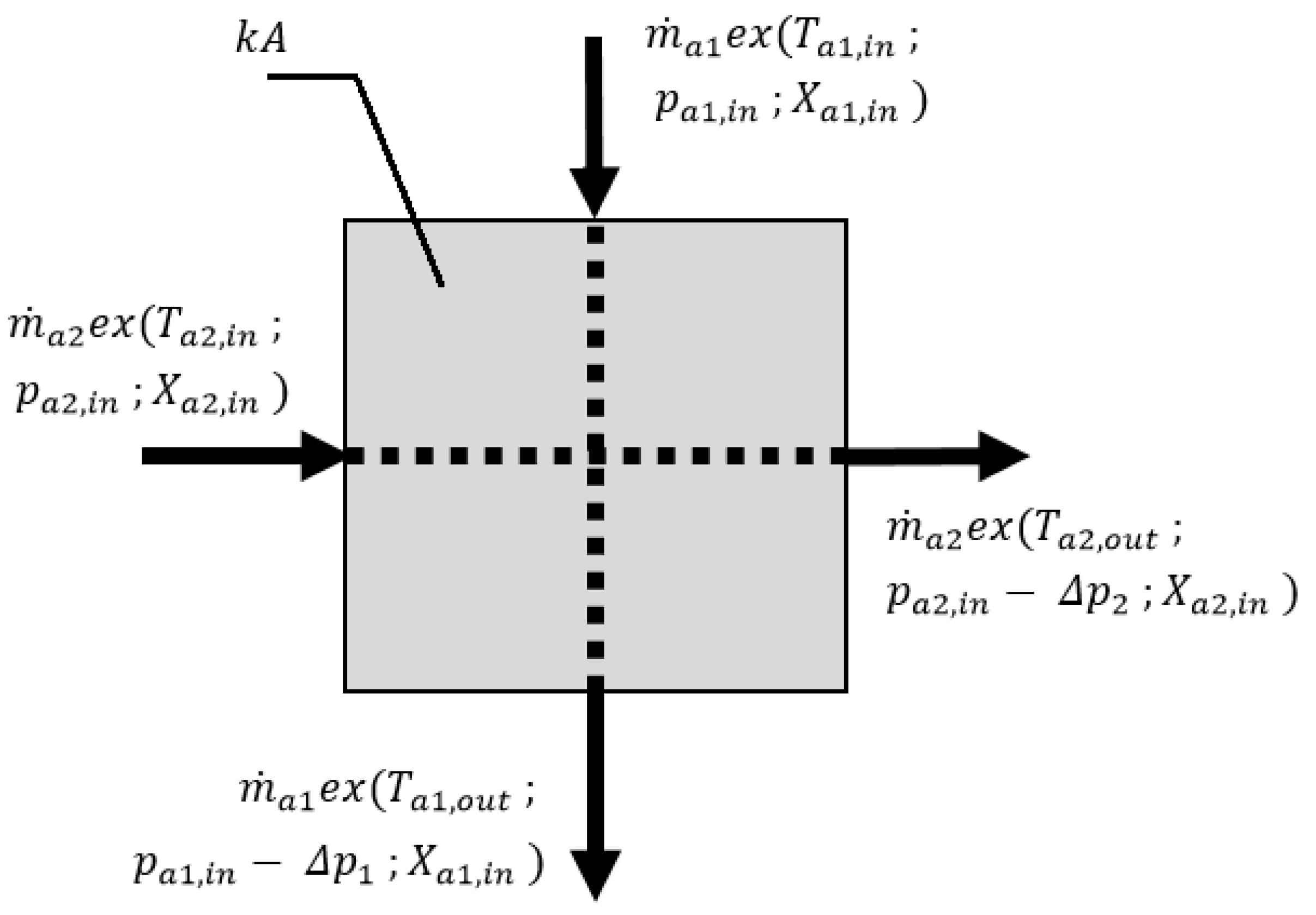
3.3. Regenerative Heat Exchanger
- The outer wall of the heat exchanger is adiabatic,
- The heat capacity of the heat exchanger is negligible,
- Condensation of water vapor on the heat exchange surfaces does not occur.
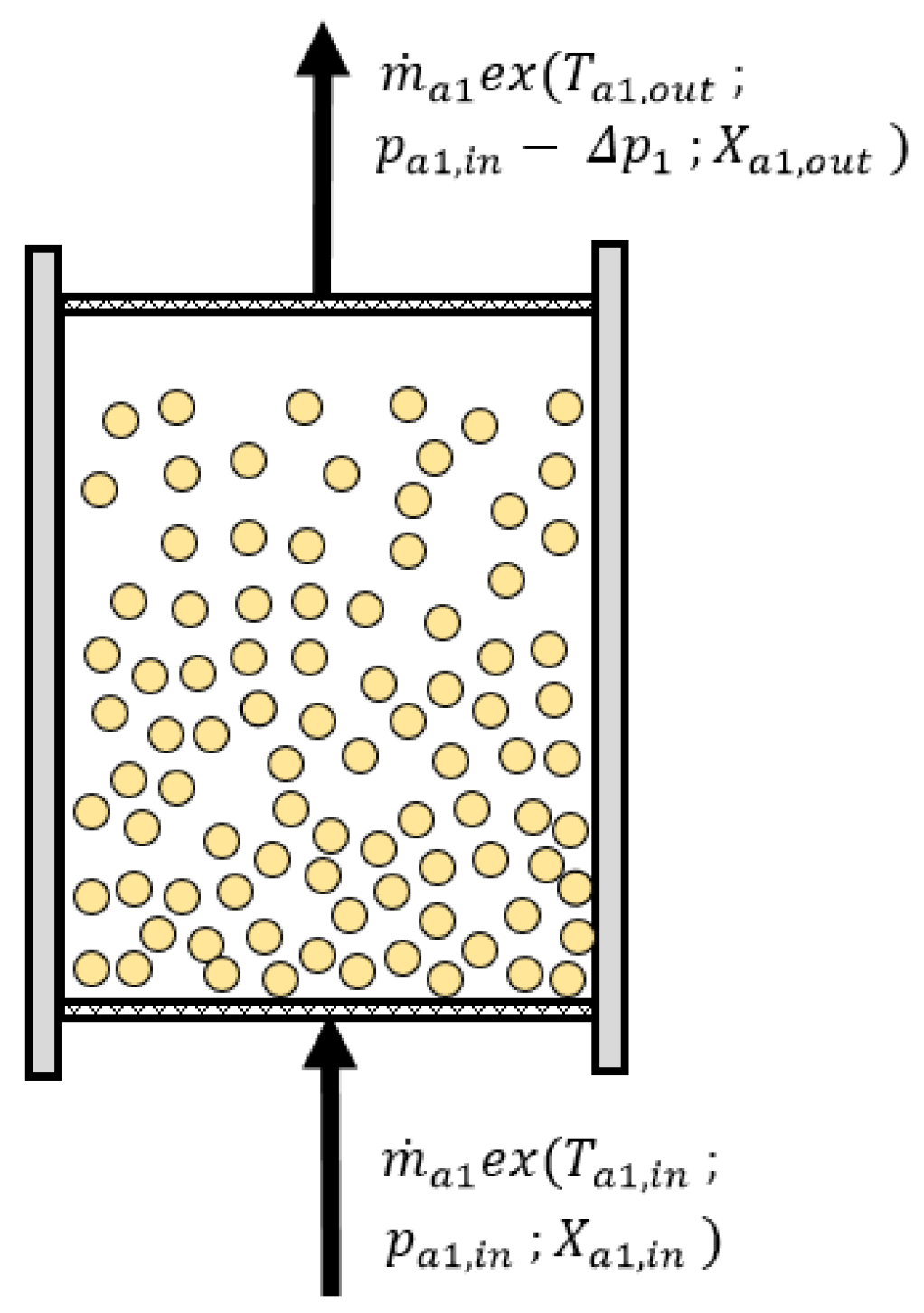
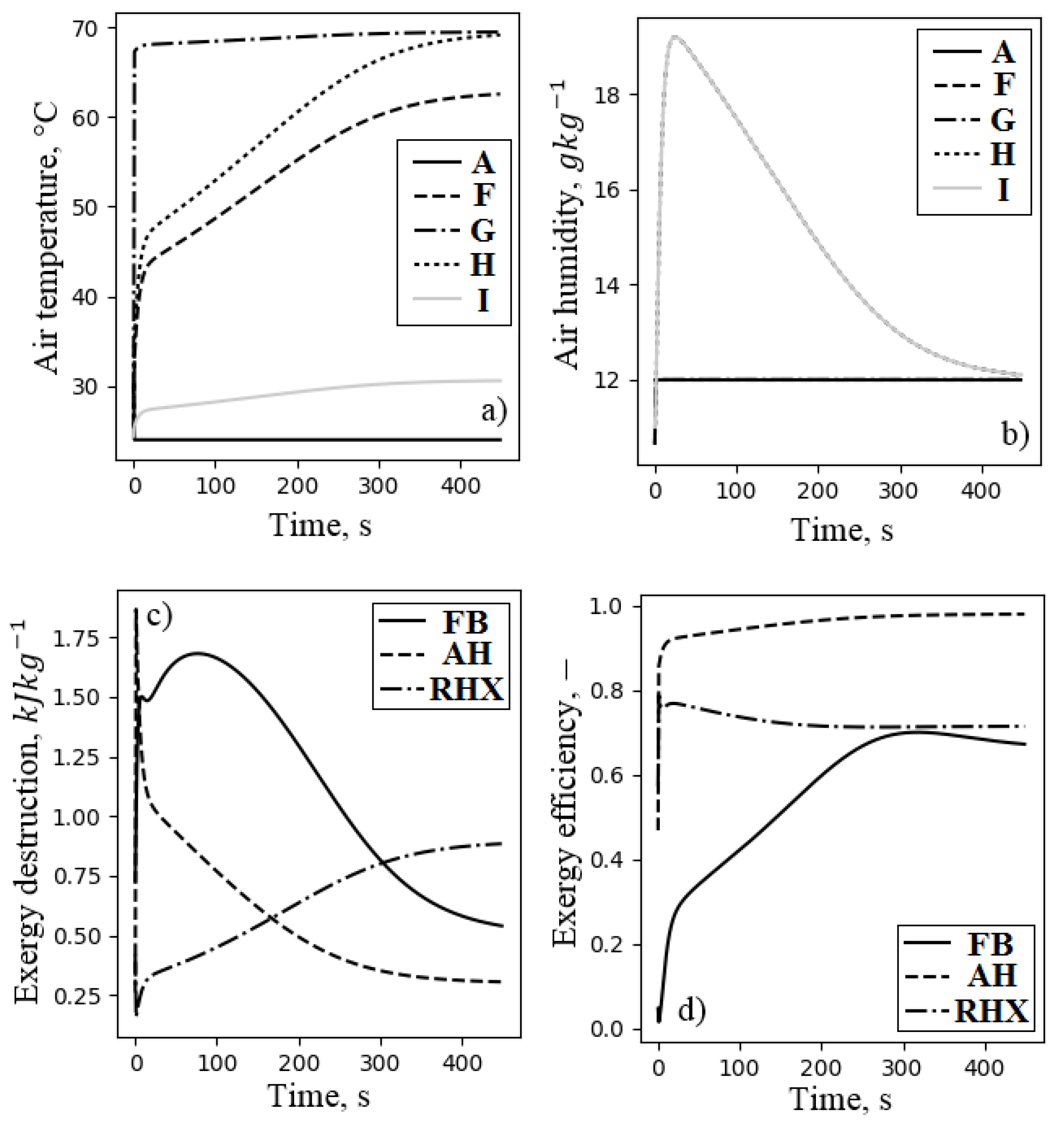
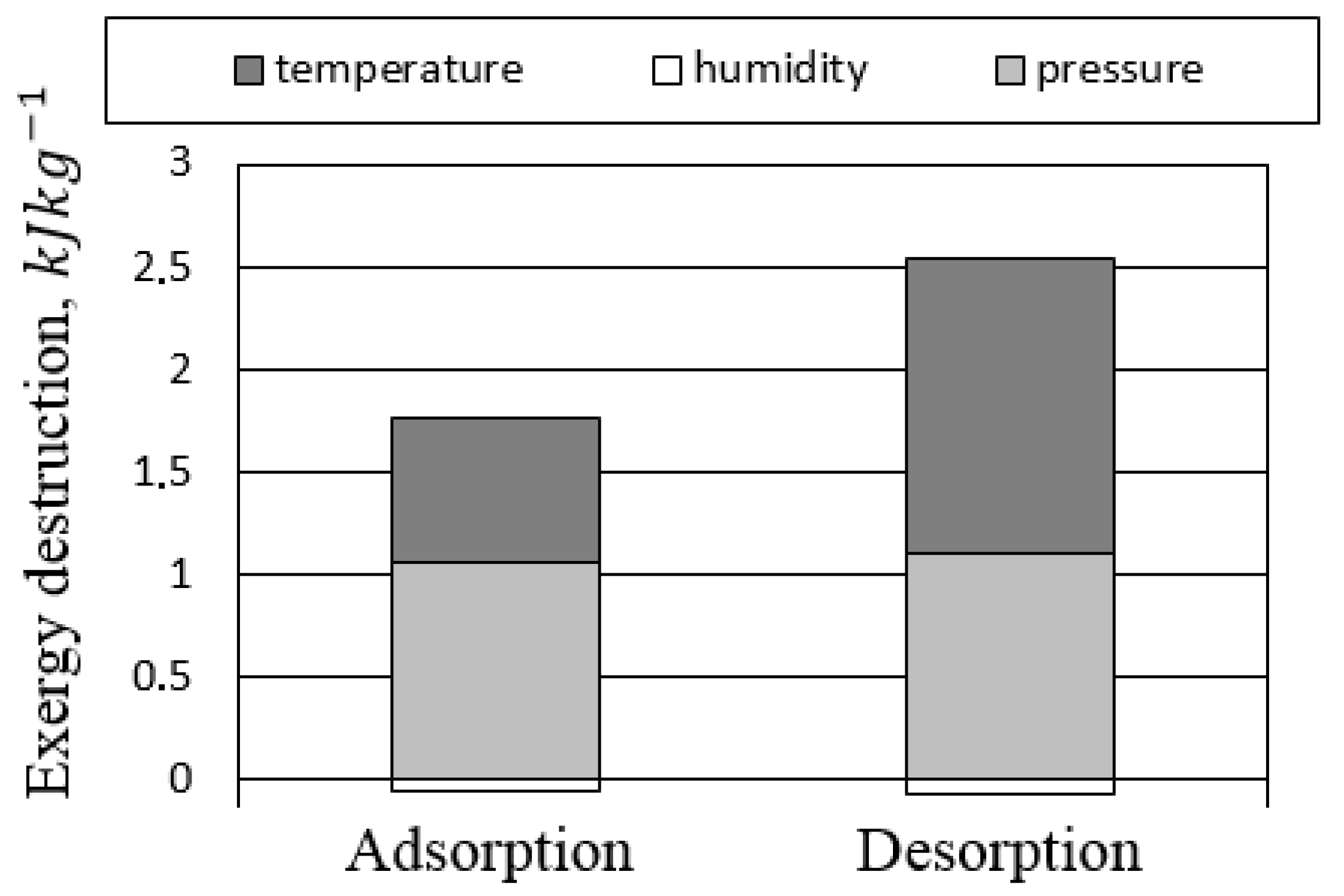
3.4. Fluidized Beds
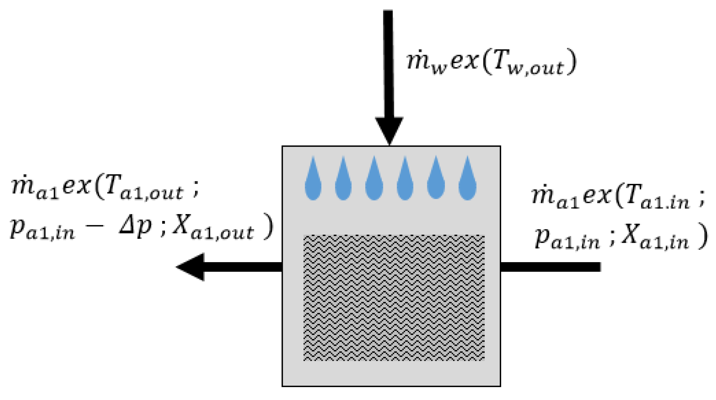
3.5. Direct Evaporative Cooler
- The outer walls of the DEC are adiabatic,
- The heat capacity of the DEC is negligible,
- The water stream supplied to the DEC undergoes complete evaporation,
- DEC generates a constant pressure drop of 25 [26],
- The heat of evaporation is exchanged at the temperature level of the outlet air.
4. Results and Discussion
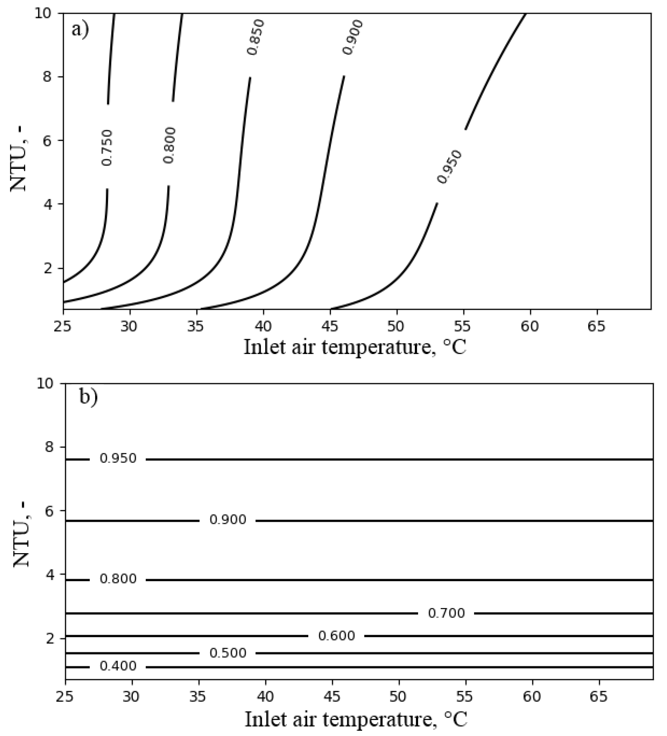
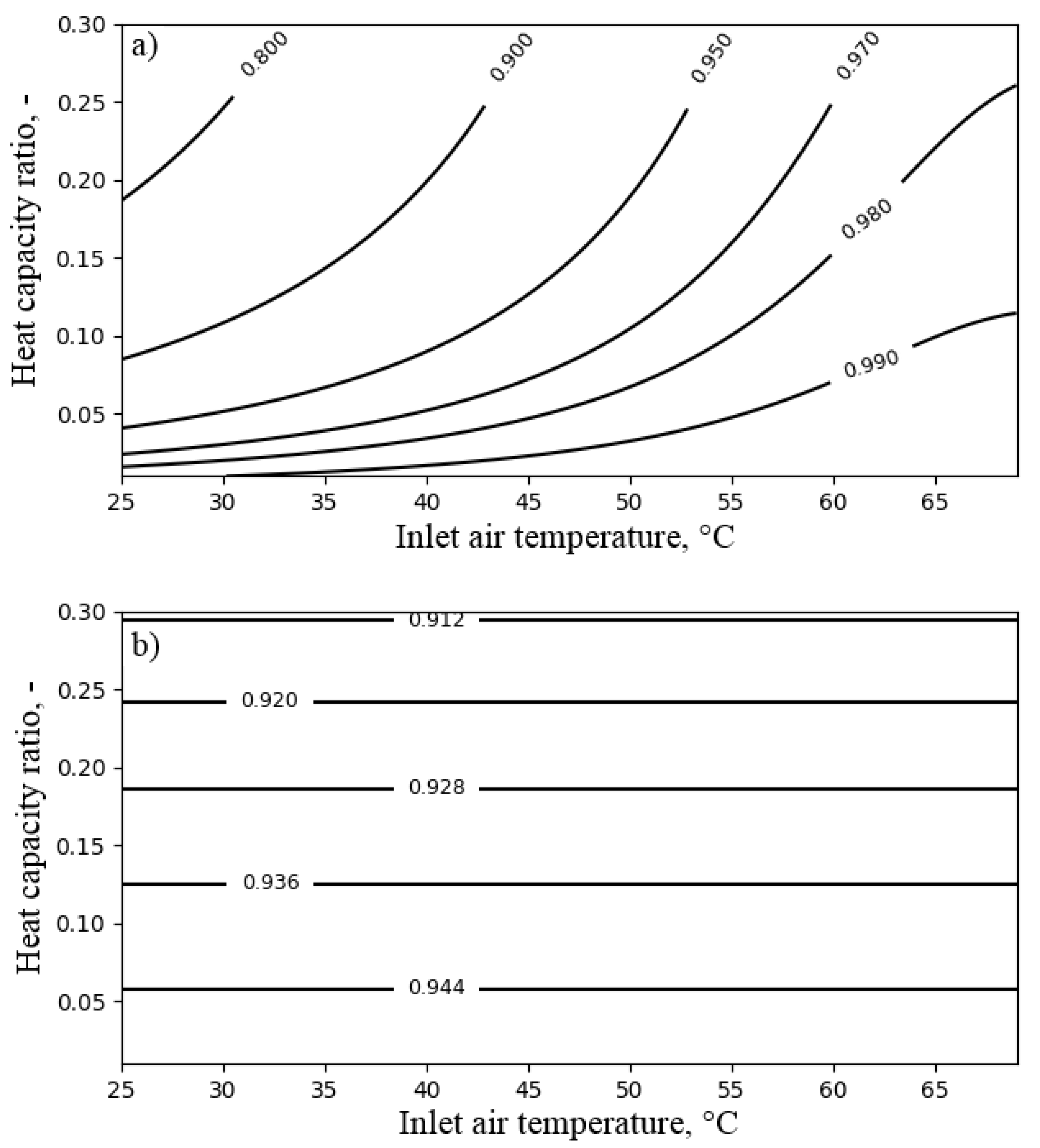
4.1. Air Cooler
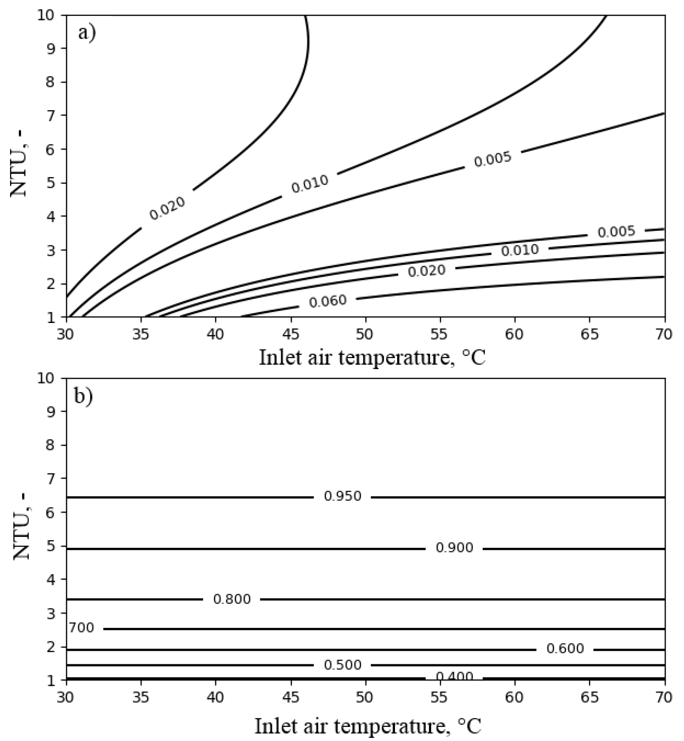
4.2. Air Heater
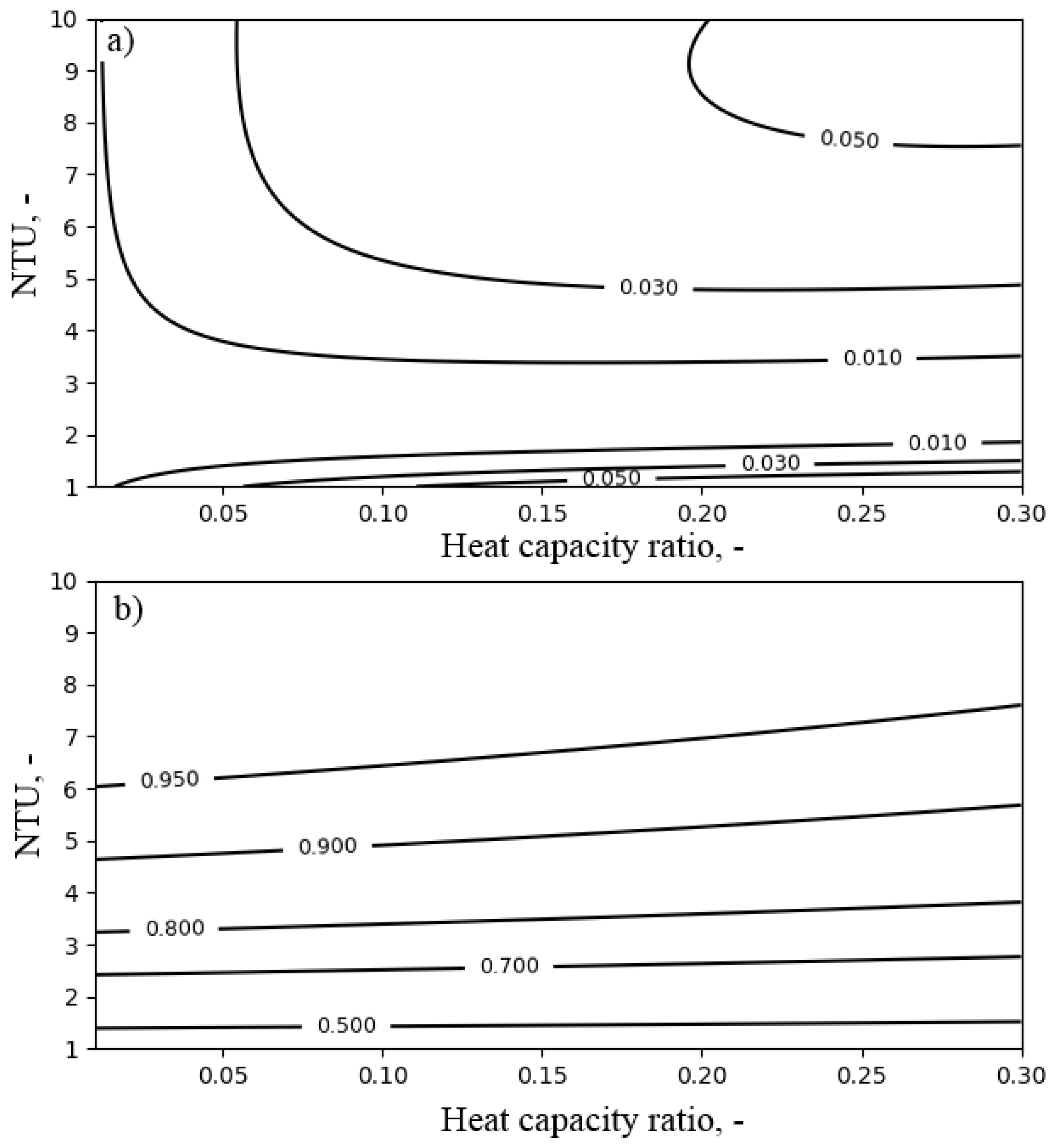
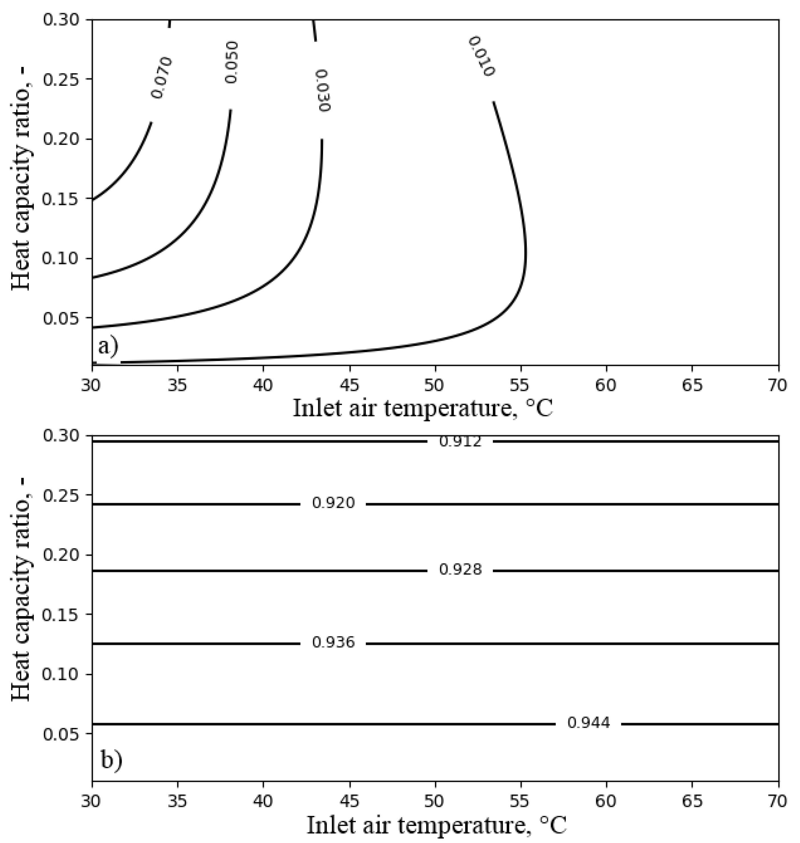
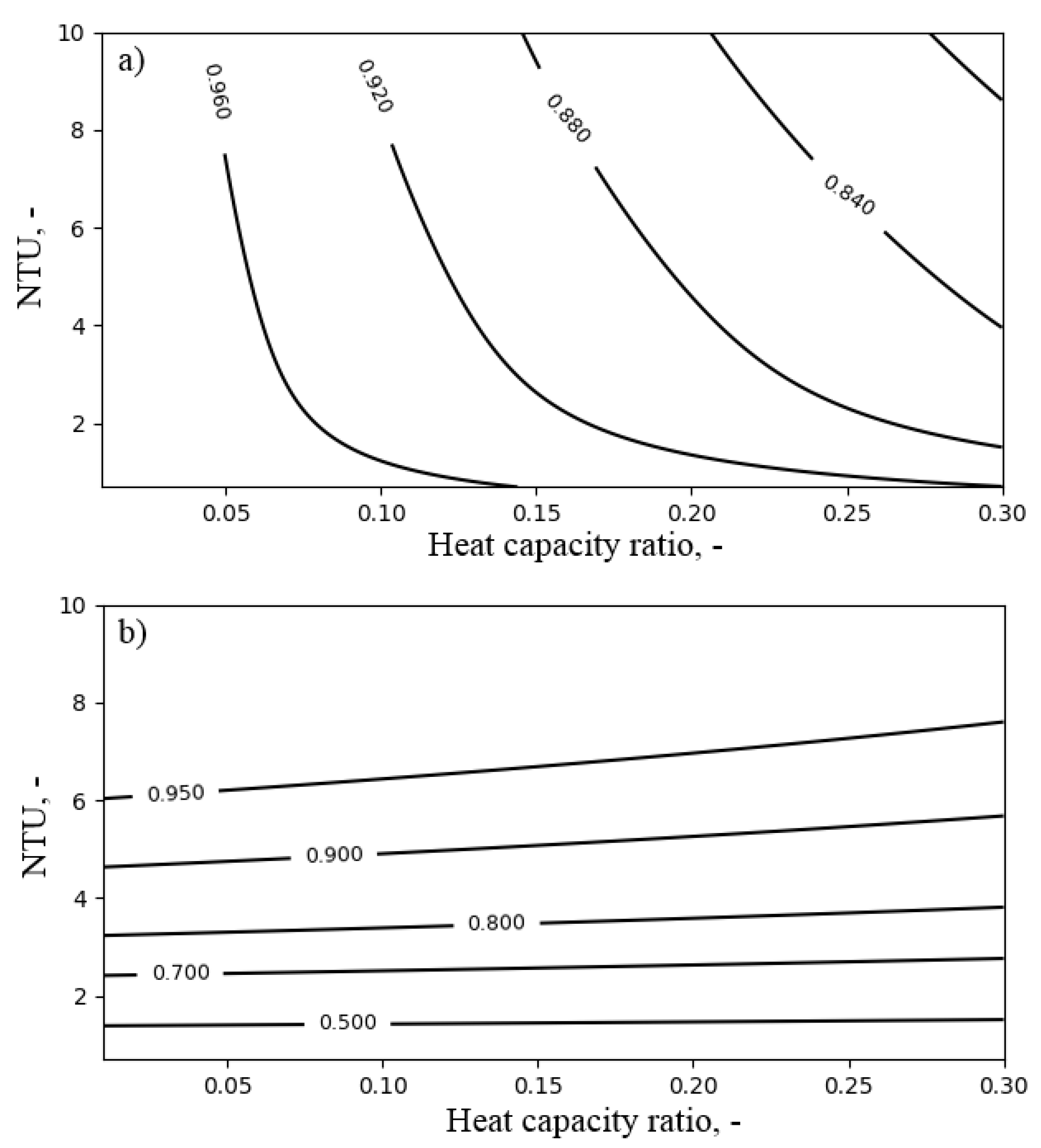
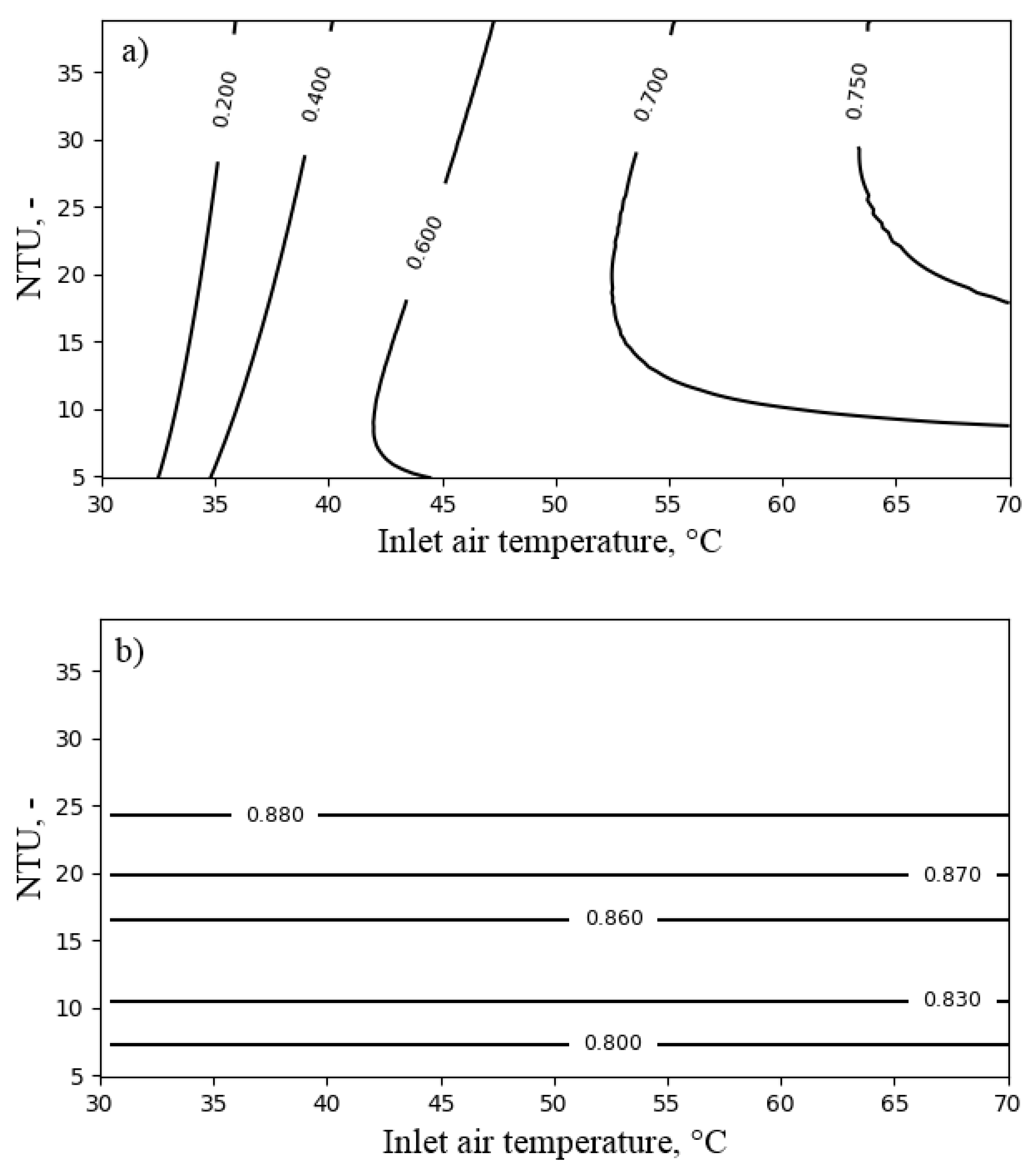
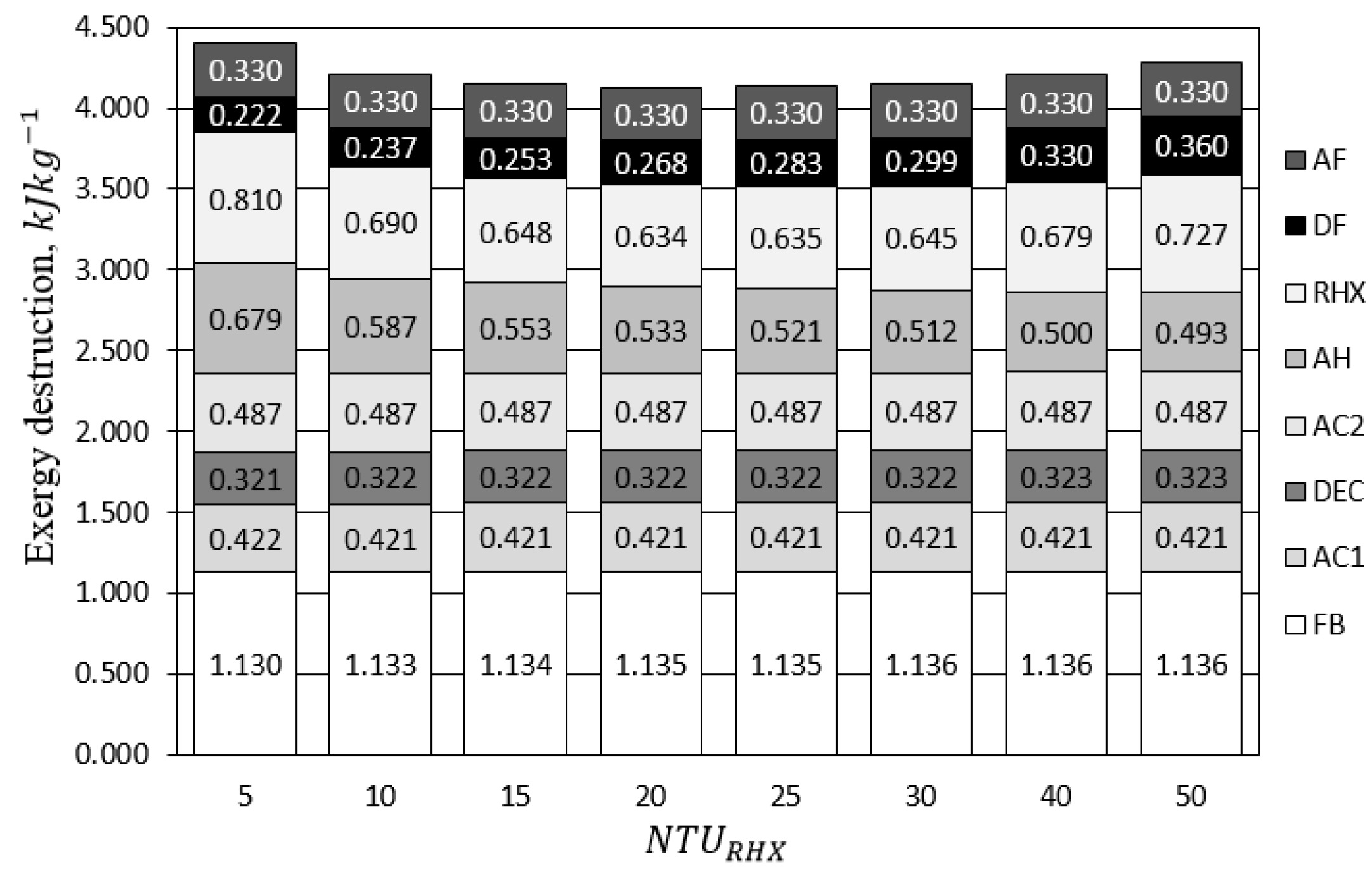
4.3. Regenerative Heat Exchanger
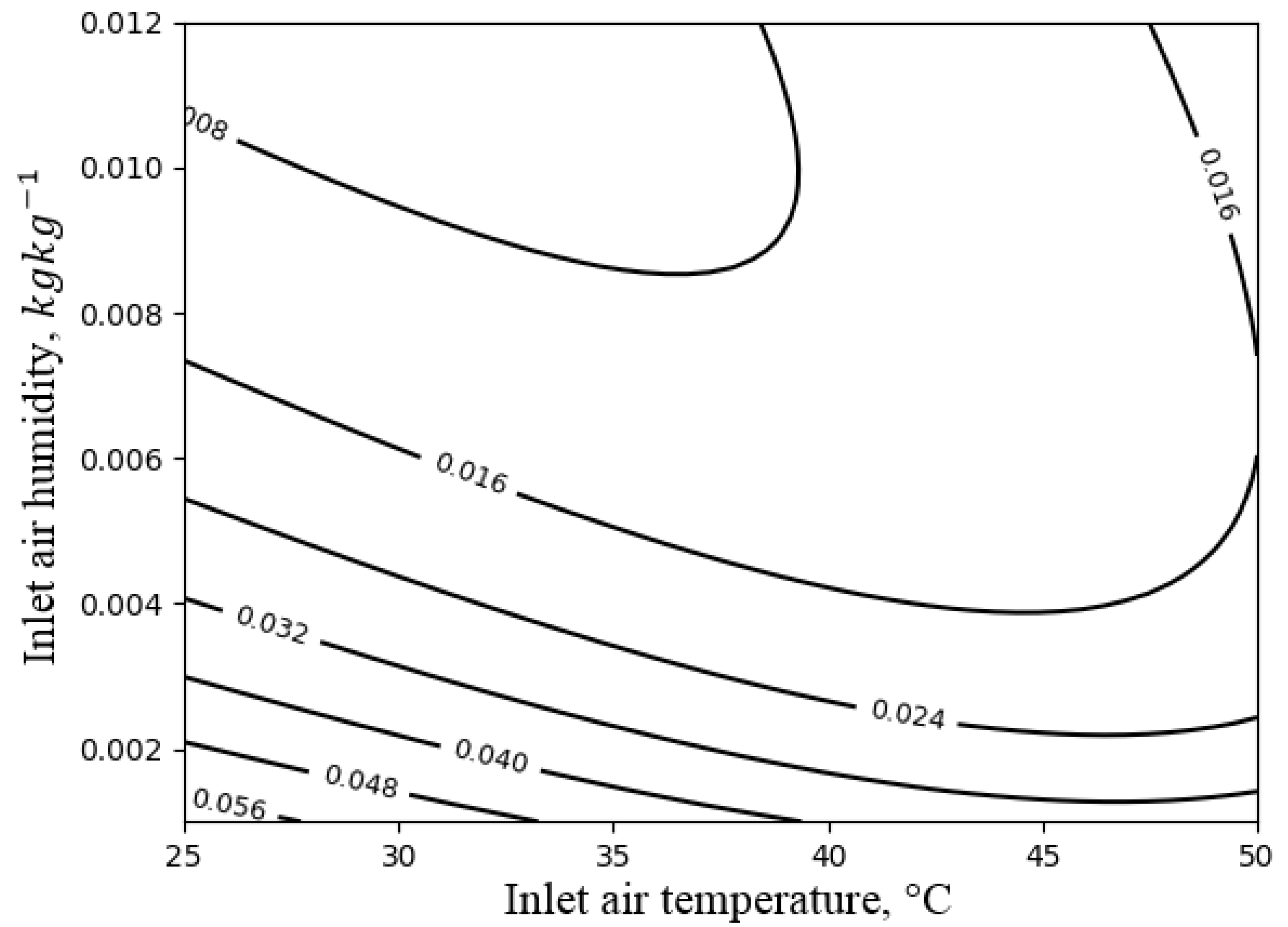
4.4. Direct Evaporative Cooler
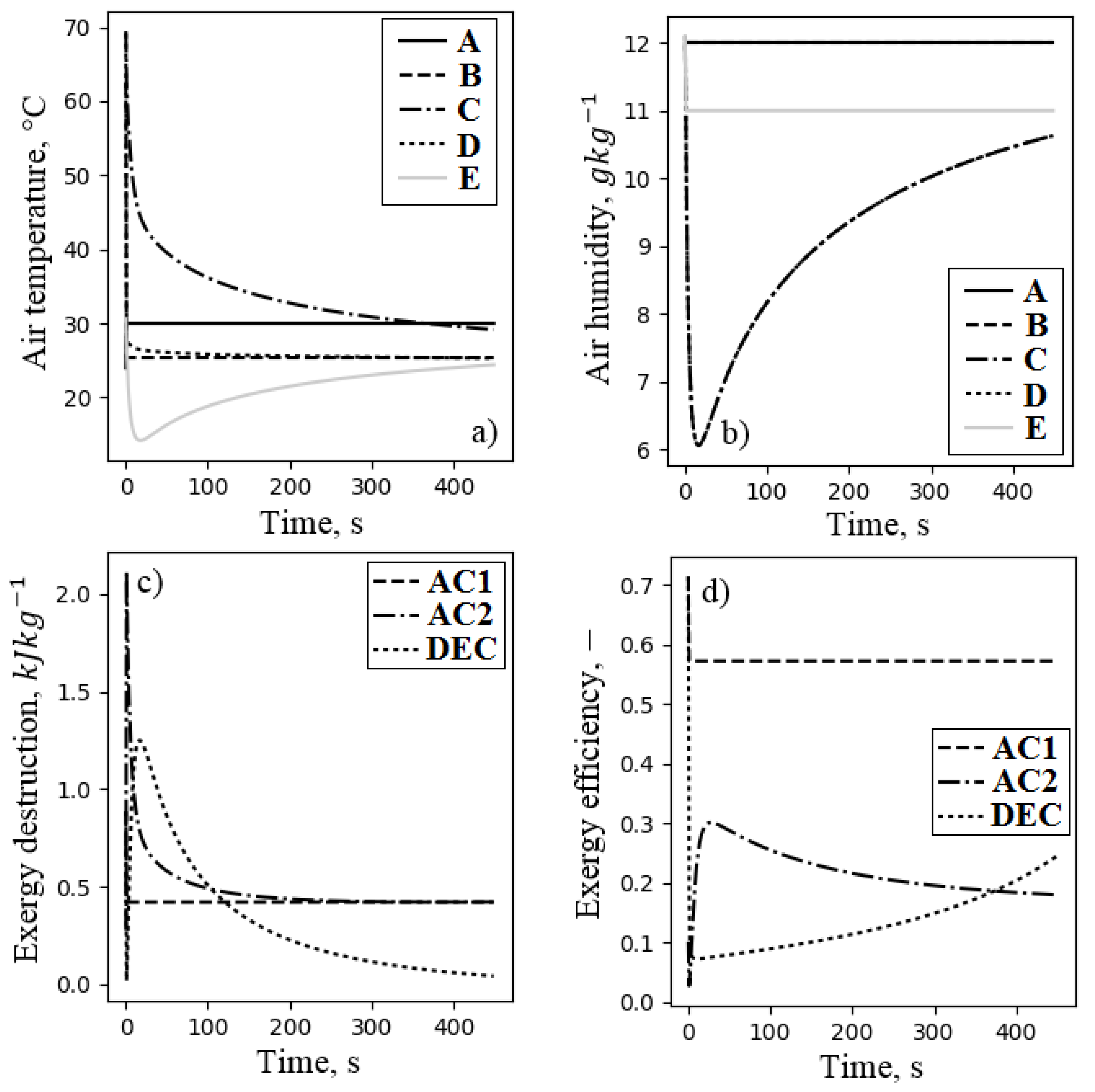
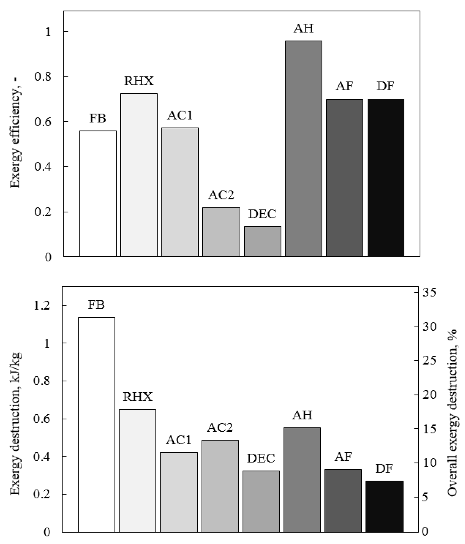
4.5. Complete System

| Name | Symbol | Unit | Quantity |
|---|---|---|---|
| Dead state humidity | 0.012 | ||
| Dead state pressure | Pa | 101300 | |
| Dead state temperature | 30 | ||
| Distance between the AC/AH fins | d | m | |
| Overall heat transfer coefficient of AC/AH | 50 | ||
| Overall heat transfer coefficient of RHX | 25 | ||
| Dimension of the RHX channel | m | 0.01 | |
| Dimension of the RHX channel | m | 0.003 | |
| Number of heat transfer units of AC/AH | − | 6 | |
| Number of heat transfer units of RHX | − | 20 | |
| Heat capacity ratio of AC/AH | − | 0.2 | |
| Air velocity in heat exchangers | U | 3 |
5. Conclusions
- The total exergy destruction in FDC was 4.163 , and the exergy efficiency was found to be 0.577.
- The main sources of exergy losses in FDC were the fluidized beds and the regenerative heat exchanger. These components were responsible for 30% and 20% of the total exergy destruction, respectively. Nevertheless, both components were characterized by relatively high exergy efficiency of 0.58 and 0.77, respectively.
- Optimization of the RHX exergy destruction led also to the decrease of exergy losses in the air heater. For the analyzed case, the optimum was found to be about 20.
- The most inefficient components of FDC were the direct evaporative cooler and the air cooler (featuring an exergy efficiency of 10% and 20%, respectively).
- In order to improve the exergy efficiency, the direct evaporative cooler can be replaced with indirect or indirect/direct evaporative cooling. However, this can result in a significant decrease of the system’s capacity.
- The air cooler efficiency was low due to the dissipation of outlet water exergy. Recovery of this exergy flow would reduce the exergy destruction by 25%.
- Nearly 30% of exergy destruction occurred due to the pressure drop in FDC components. This was caused by a low density and heat capacity of the air. The decrease of the overall pressure drop can significantly improve the exergy efficiency.
Author Contributions
Funding
Conflicts of Interest
Abbreviations
| Acronyms | ||
| Coefficient of performance | ||
| Air cooler | ||
| Air heater | ||
| Adsorption circuit fan | ||
| Desorption circuit fan | ||
| Regenerative heat exchanger | ||
| Direct evaporative cooler | ||
| Greek symbols | ||
| Efficiency | ||
| Dynamic viscosity | ||
| Density | ||
| Symbols | ||
| A | Heat exchange surface | |
| c | Specific heat | |
| d | Channel dimension of the RHX | m |
| Specific exergy | ||
| Specific exergy destruction | ||
| E | Parameter of the heat exchanger | - |
| Flow of exergy | W | |
| Exergy destruction | W | |
| F | Correction factor | - |
| h | Specific enthalpy | |
| Heat of evaporation | ||
| k | Overall heat transfer coefficient | |
| l | Channel dimension of the RHX | m |
| Mass flow | ||
| Number of heat transfer units | - | |
| p | pressure | Pa |
| P | Temperature ratio | - |
| Q | Heat flow | W |
| R | Individual gas constant | |
| Heat capacity ratio | - | |
| s | Specific entropy | |
| T | Temperature | K |
| U | Velocity | |
| w | Channel dimension of the air heater/cooler | m |
| X | Specific humidity ratio | |
| Specific humidity ratio on a molar basis | ||
| Subscripts | ||
| 0 | Dead state | |
| a | Air | |
| The Carnot cycle | ||
| Destruction | ||
| Exergy | ||
| H | Heat source | |
| Inlet | ||
| L | Cooling effect | |
| M | Heat sink | |
| v | Vapor | |
| w | Water |
References
- Rogala, Z.; Kolasiński, P.; Gnutek, Z. Effect of operating conditions on performance of silica gel-water air-fluidised desiccant cooler. In E3S Web of Conferences ASEE17; EDP Sciences: Les Ulis, France, 2017; Volume 22. [Google Scholar]
- Chen, C.H.; Ma, S.S.; Wu, P.H.; Chiang, Y.C.; Chen, S.L. Adsorption and desorption of silica gel circulating fluidized beds for air conditioning systems. Appl. Energy 2015, 155, 708–718. [Google Scholar] [CrossRef]
- Chen, C.H.; Schmid, G.; Chan, C.T.; Chiang, Y.C.; Chen, S.L. Application of silica gel fluidised bed for air-conditioning systems. Appl. Therm. Eng. 2015, 89, 229–238. [Google Scholar] [CrossRef]
- Horibe, A.; Sukmawaty; Haruki, N.; Hiraishi, D. Continuous Sorption and Desorption of Organic Sorbent Powder in Two Connected Fluidized Beds. J. Therm. Sci. Technol. 2012, 7, 563–576. [Google Scholar] [CrossRef][Green Version]
- Ramzy, A.; Kadoli, R. Modified PGC model and its validation by experiments for heat and moisture transfer analysis in a vertical fluidized desiccant bed. Appl. Therm. Eng. 2015, 81, 83–91. [Google Scholar] [CrossRef]
- Xiong, Z.Q.; Dai, Y.J.; Wang, R.Z. Development of a novel two-stage liquid desiccant dehumidification system assisted by CaCl2 solution using exergy analysis method. Appl. Energy 2010, 87, 1495–1504. [Google Scholar] [CrossRef]
- Zhang, T.; Liu, X.; Tang, H.; Liu, J.; Jiang, Y. Exergy and entransy analyses in air-conditioning system part 1—Similarity and distinction. Energy Build. 2016, 128, 876–885. [Google Scholar] [CrossRef]
- Peng, D.; Zhou, J.; Luo, D. Exergy analysis of a liquid desiccant evaporative cooling system. Int. J. Refrig. 2017, 82, 495–508. [Google Scholar] [CrossRef]
- Chiang, Y.C.; Chen, C.H.; Chiang, Y.C.; Chen, S.L. Circulating inclined fluidized beds with application for desiccant dehumidification systems. Appl. Energy 2016, 175, 199–211. [Google Scholar] [CrossRef]
- Liu, X.H.; Zhang, T.; Zheng, Y.W.; Tu, R. Performance investigation and exergy analysis of two-stage desiccant wheel systems. Renew. Energy 2016, 86, 877–888. [Google Scholar] [CrossRef]
- Tu, R.; Liu, X.H.; Jiang, Y. Irreversible processes and performance improvement of desiccant wheel dehumidification and cooling systems using exergy. Appl. Energy 2015, 145, 331–344. [Google Scholar] [CrossRef]
- Hamed, A.M.; Abd, W.R.; Rahman, E. Experimental study of the transient adsorption/desorption characteristics of silica gel particles in fluidized bed. Energy 2010, 35, 2468–2483. [Google Scholar] [CrossRef]
- Zabierowski, P. Mass Transfer in the Adsorption Process of Water Vapour in a Confined Fluidized Bed. Chem. Process Eng. 2009, 30, 389–402. [Google Scholar]
- Rogala, Z.; Kolasiński, P.; Gnutek, Z. Modelling and experimental analyzes on air-fluidised silica gel-water adsorption and desorption. Appl. Therm. Eng. J. 2017, 127, 950–962. [Google Scholar] [CrossRef]
- Chorowski, M.; Pyrka, P. Modelling and experimental investigation of an adsorption chiller using low-temperature heat from cogeneration. Energy 2015, 92, 221–229. [Google Scholar] [CrossRef]
- Szargut, J. Exergy Method: Technical and Ecological Applications; WIT Press: Southampton, UK, 2005; p. 192. [Google Scholar]
- Martinaitis, V.; Biekša, D.; Bielskus, J. The exergy efficiency assessment of heat recovery exchanger for air handling units, using a state property—Coenthalpy. Appl. Therm. Eng. 2016, 108, 388–397. [Google Scholar] [CrossRef]
- Dincer, I.; Rosen, A.M. Exergy: Energy, Environment and Sustainable Development; Elsevier Ltd.: Amsterdam, The Netherlands, 2007. [Google Scholar]
- Shuiqing, Z.; Hongying, D.; Shengchang, Z. Investigation on the Performance of Forward Bending Fan. Int. J. Turbo Jet Engines 2019, 36, 207–217. [Google Scholar] [CrossRef]
- Jeter, S.M. Effectiveness and LMTD Correction Factor of the Cross Flow Exchanger: A Simplified and Unified Treatment. In Proceedings of the 2006 ASEE Southeast Section Conference, Tuscaloosa, AL, USA, 2–4 April 2006. [Google Scholar]
- Cengel, Y.A.; Klein, S.; Beckman, W. Heat Transfer: A Practical Approach, 2nd ed.; Mcgraw-Hill: New York, NY, USA, 2002; p. 896. [Google Scholar]
- Liang, C.; Tong, X.; Lei, T.; Li, Z.; Wu, G. Optimal Design of an Air-to-Air Heat Exchanger with Cross-Corrugated Triangular Ducts by Using a Particle Swarm Optimization Algorithm. Appl. Sci. 2017, 7, 554. [Google Scholar] [CrossRef]
- Deshko, V.I.; Ya, A.; Sukhodub, I.O. Heat and mass transfer in cross-flow air-to-air membrane heat exchanger in heating mode. Appl. Therm. Eng. 2016, 100, 133–145. [Google Scholar] [CrossRef]
- Li, Z.X.; Zhong, T.S.; Niu, J.L.; Xiao, F.; Zhang, L.Z. Conjugate heat and mass transfer in a total heat exchanger with cross-corrugated triangular ducts and one-step made asymmetric membranes. Int. J. Heat Mass Transf. 2015, 84, 390–400. [Google Scholar] [CrossRef]
- Sourbron, M.; Kovacevic, I. The numerical model for direct evaporative cooler. Appl. Therm. Eng. 2017, 113, 8–19. [Google Scholar]
- Farmahini-Farahani, M.; Delfani, S.; Esmaeelian, J. Exergy analysis of evaporative cooling to select the optimum system in diverse climates. Energy 2012, 40, 250–257. [Google Scholar] [CrossRef]
- Shahzad, M.K.; Qadar, G.; Ali, M.; Ahmed, N.; Khalil, M.S.; Ur, T. Experimental evaluation of a solid desiccant system integrated with cross flow Maisotsenko cycle evaporative cooler. Appl. Therm. Eng. 2018, 128, 1476–1487. [Google Scholar] [CrossRef]
- Lin, J.; Wang, R.Z.; Kumja, M.; Bui, T.D.; Chua, K.J. Modelling and experimental investigation of the cross-flow dew point evaporative cooler with and without dehumidification. Appl. Therm. Eng. 2017, 121, 1–13. [Google Scholar] [CrossRef]


| Name | Symbol | Unit | Quantity |
|---|---|---|---|
| Desiccant filling height | m | 0.03 | |
| Switching time | s | 450 | |
| Superficial air velocity | 3 | ||
| Desiccant particle diameter | m | 0.001 | |
| Fluidised bed height | m | 0.55 | |
| Fluidised bed diameter | m | 0.28 | |
| Desiccant density | 850 | ||
| Inlet temperature of heating water | 70 | ||
| Inlet temperature of cooling water | 25 |
© 2019 by the authors. Licensee MDPI, Basel, Switzerland. This article is an open access article distributed under the terms and conditions of the Creative Commons Attribution (CC BY) license (http://creativecommons.org/licenses/by/4.0/).
Share and Cite
Rogala, Z.; Kolasiński, P. Exergy Analysis of Fluidized Desiccant Cooling System. Entropy 2019, 21, 757. https://doi.org/10.3390/e21080757
Rogala Z, Kolasiński P. Exergy Analysis of Fluidized Desiccant Cooling System. Entropy. 2019; 21(8):757. https://doi.org/10.3390/e21080757
Chicago/Turabian StyleRogala, Zbigniew, and Piotr Kolasiński. 2019. "Exergy Analysis of Fluidized Desiccant Cooling System" Entropy 21, no. 8: 757. https://doi.org/10.3390/e21080757
APA StyleRogala, Z., & Kolasiński, P. (2019). Exergy Analysis of Fluidized Desiccant Cooling System. Entropy, 21(8), 757. https://doi.org/10.3390/e21080757