Thermodynamic Investigation of an Integrated Solar Combined Cycle with an ORC System


Abstract
:
1. Introduction
1.1. Literaure Review
1.2. Motivation
2. System Description
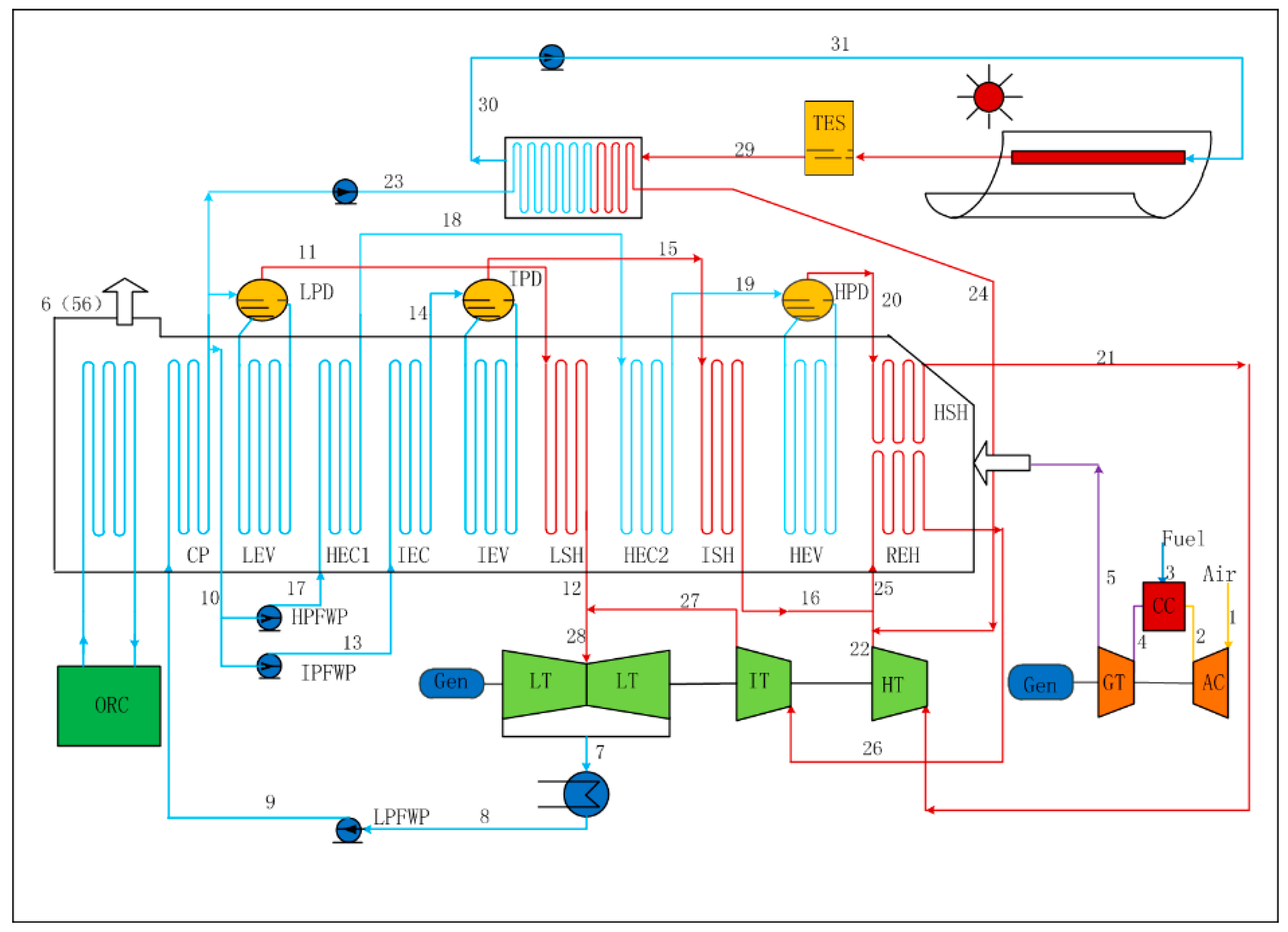
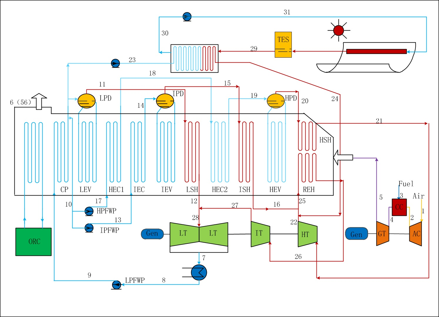
2.1. Integrated Solar Combined Cycle System
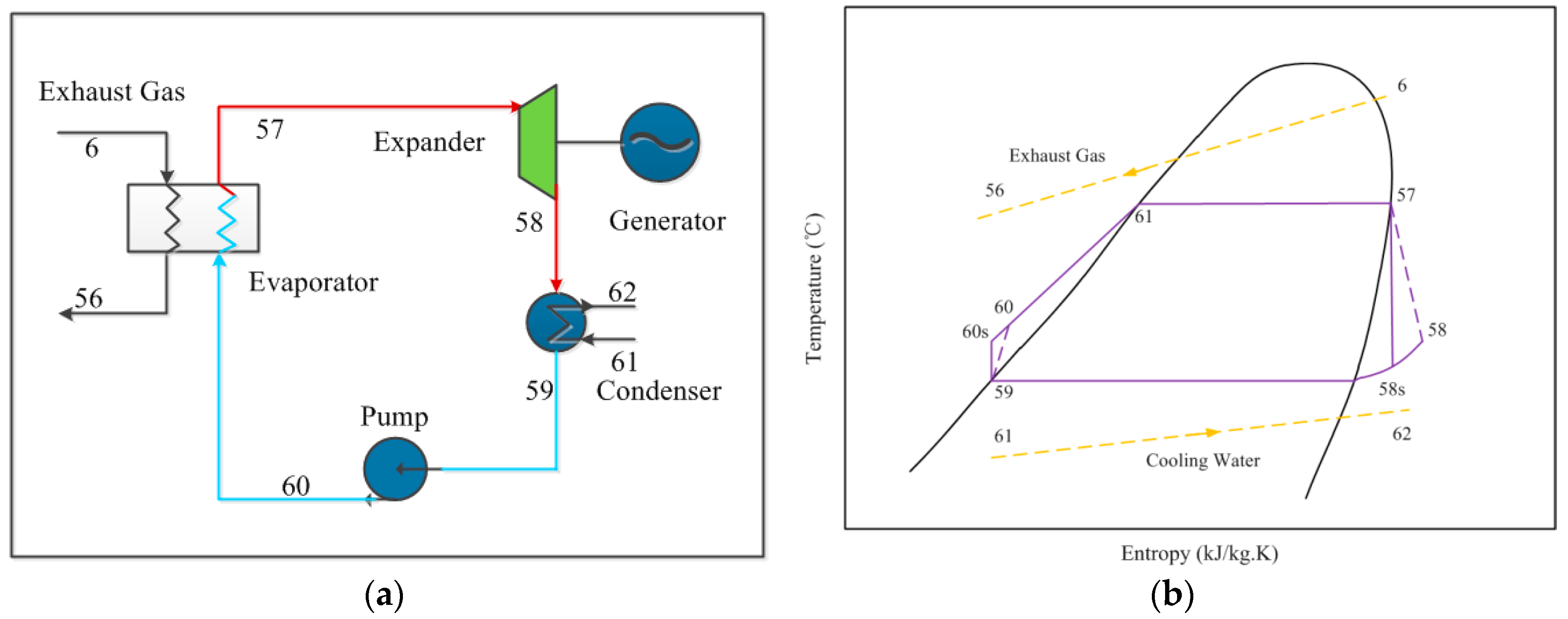
2.2. The Organic Rankine Cycle Subsystem
3. Modeling Methodology
3.1. ISCC Subsystem Modeling
3.2. ORC Subsystem Modeling
4. Results and Discussion
4.1. ISCC Model
4.2. ORC Model
4.3. Energy and Exergy Analysis Results of the ISCC-ORC System
4.4. Energy and Exergy Results of the ORC Subsystem
4.5. Economic Analysis
5. Conclusions
- (a)
- For the overall plant, the exhaust gas temperature of the four working fluids showed downward trends with increasing SRI. Rc318 and R113 contributed the highest and lowest exhaust gas temperature, respectively.
- (b)
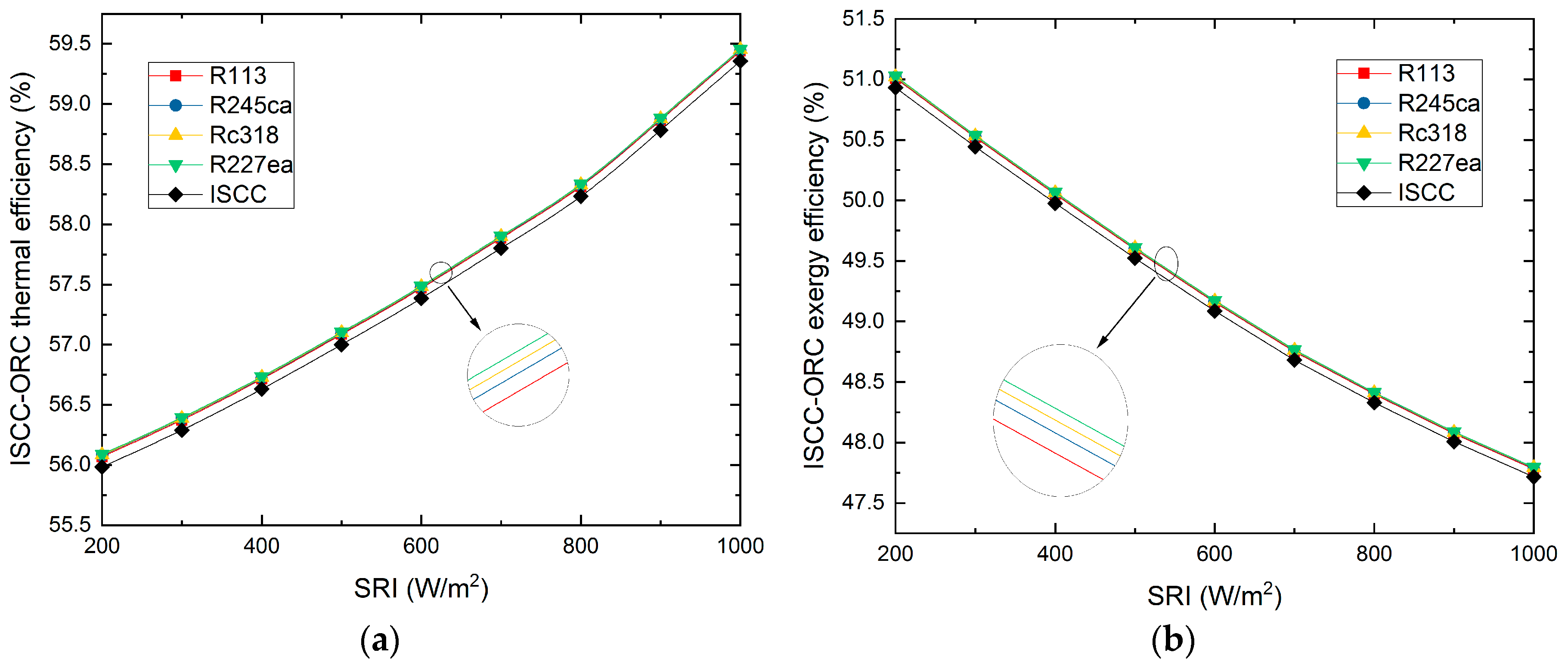
- The overall plant thermal efficiency increased rapidly with the SRI, while the exergy efficiency showed the opposite trend. The R227ea appeared to have the largest thermal efficiency of 58.33% and the highest exergy efficiency of 48.09%, at 800 W/m2. Moreover, the proposed ISCC-ORC system always had a better performance than the ISCC.
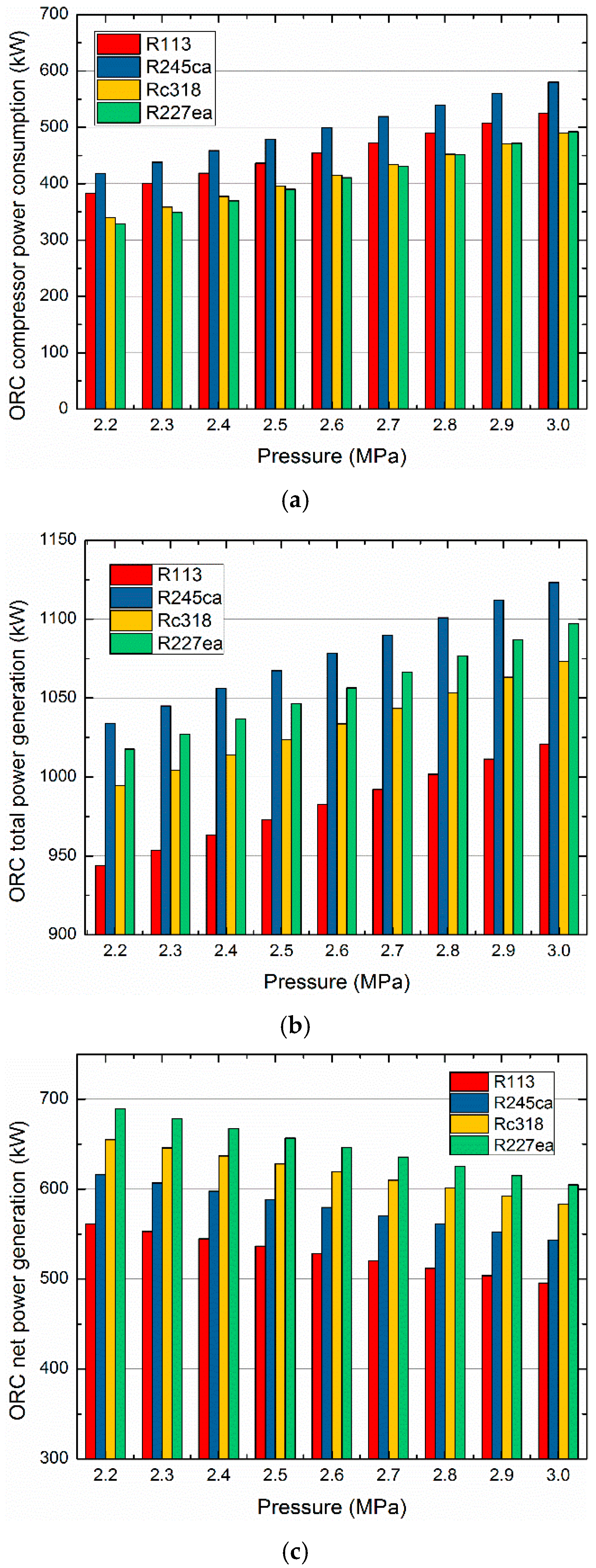
- (c)
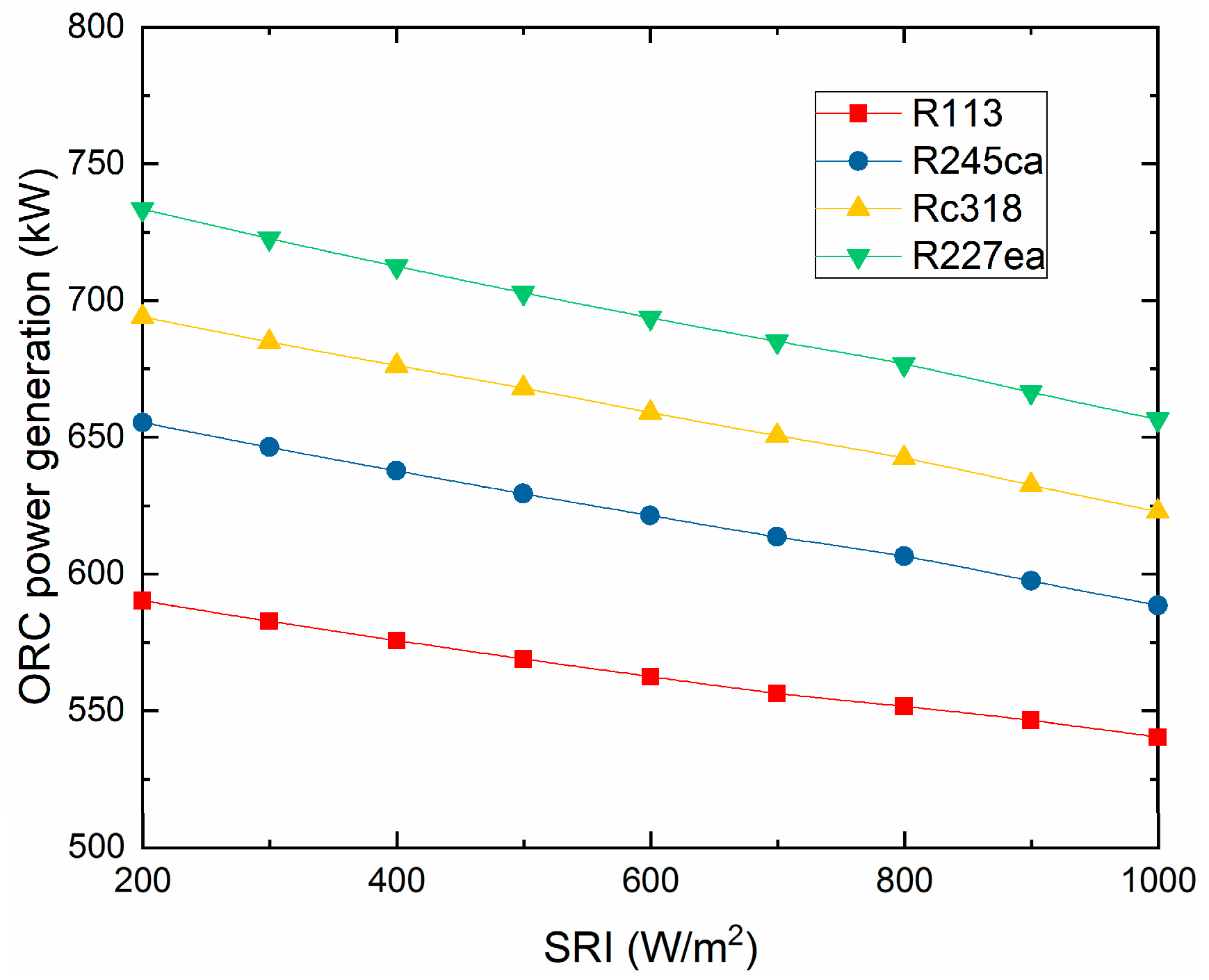
- For the ORC subsystem, the compressor power consumption and total power generation increased with the pump discharge pressure. While, the ORC net power generation showed an opposite trend. Additionally, the energy consumed by the compressor had a dominant role in the net power output of the ORC subsystem.
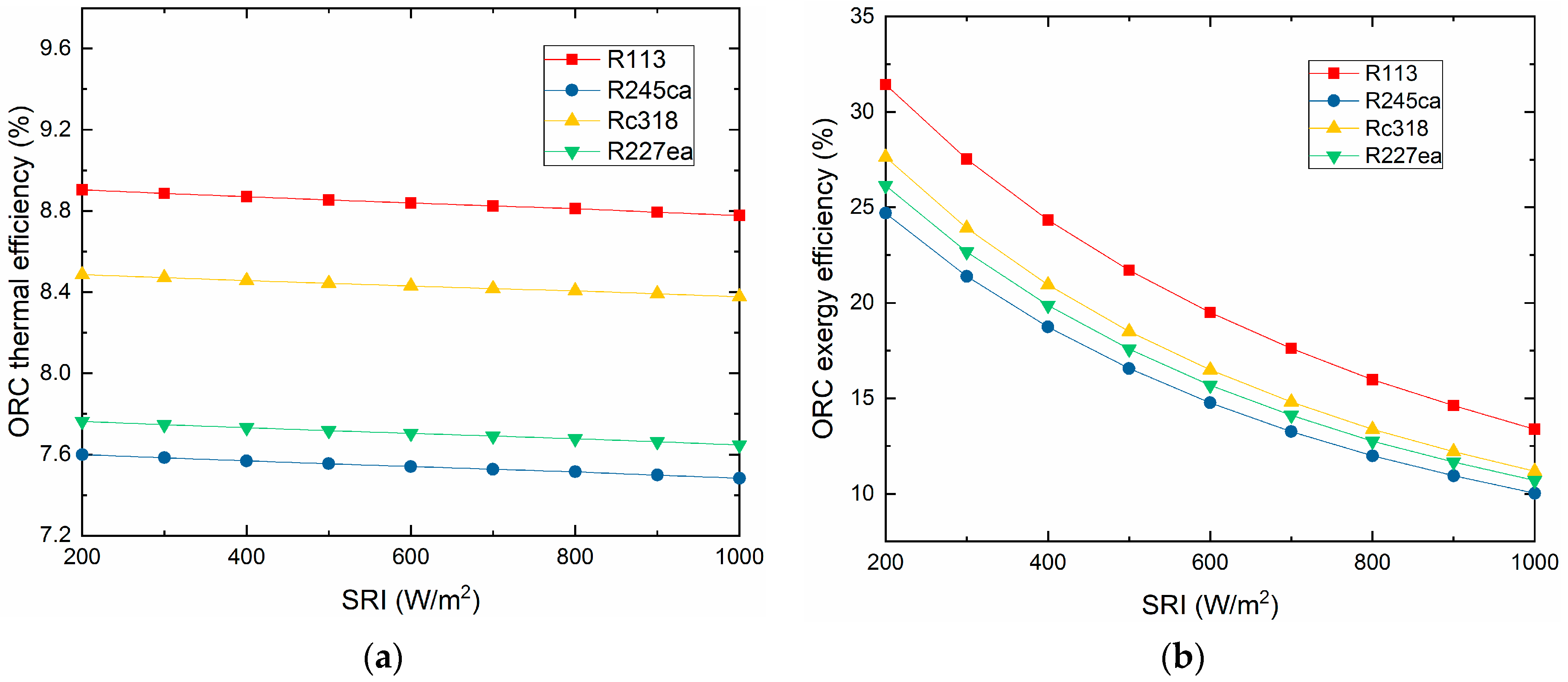
- (d)
- Both the thermal efficiency and exergy efficiency of the ORC decreased with the increasing of the SRI. Additionally, R113 showed the maximum thermal efficiency (8.81%) and exergy efficiency of (15.98%) at 800 W/m2. Meanwhile, R245ca appeared to have the minimum thermal efficiency (7.51%) and exergy efficiency (11.99%), respectively.
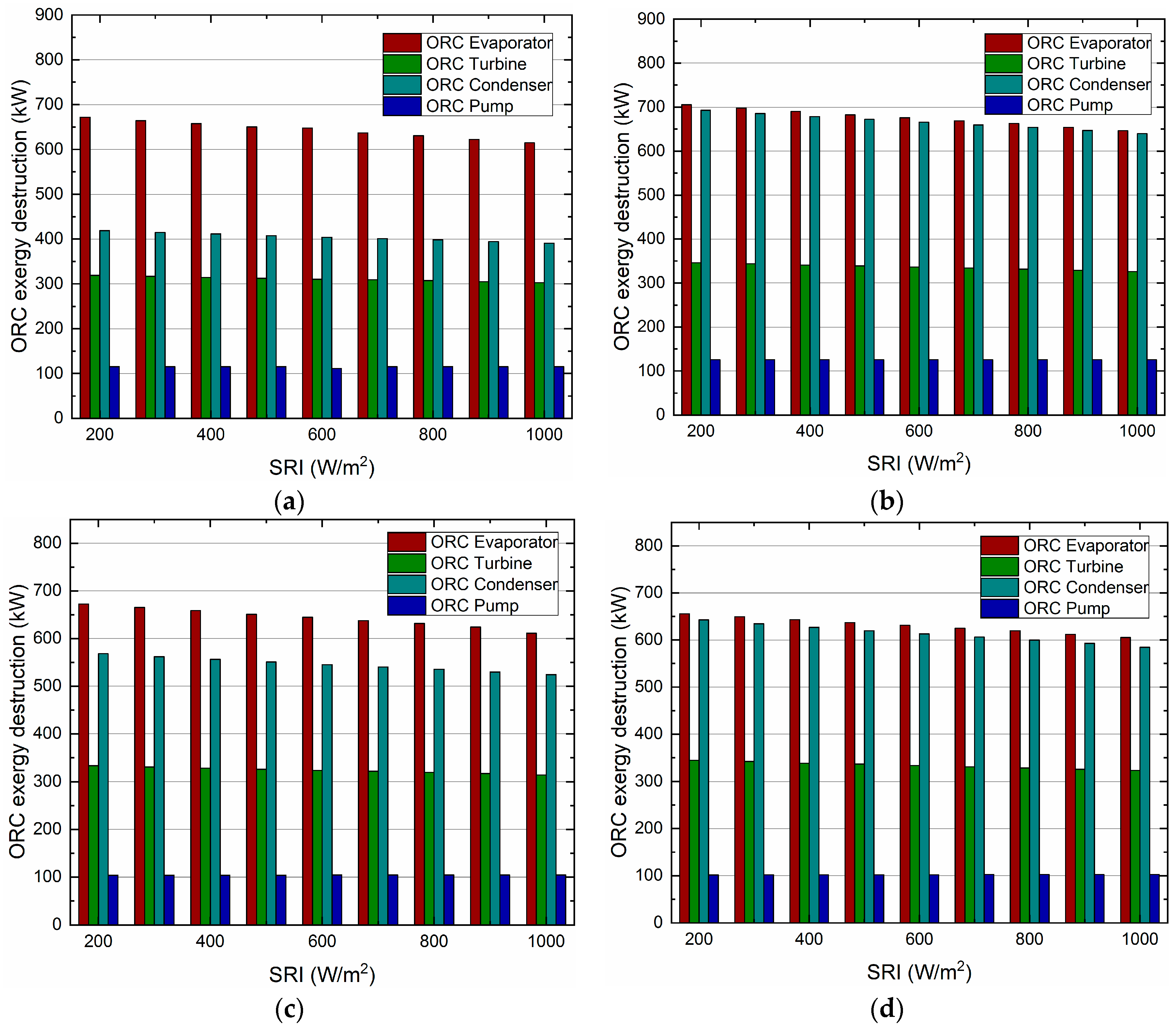
- (e)
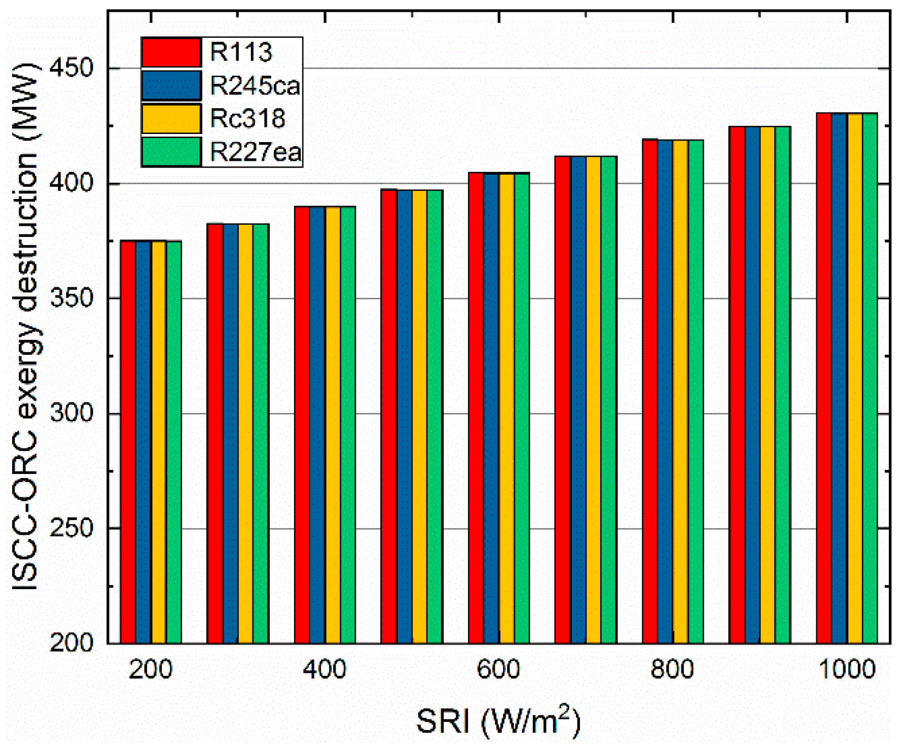
- The exergy destruction of the evaporator, turbine and condenser decreased with the increasing of the SRI. In addition, the evaporator contributed the largest exergy destruction among the selected organic working fluids followed by the turbine, condenser and pump. Besides, among all considered refrigerants, R245ca corresponded to the largest exergy destruction of the ORC system.
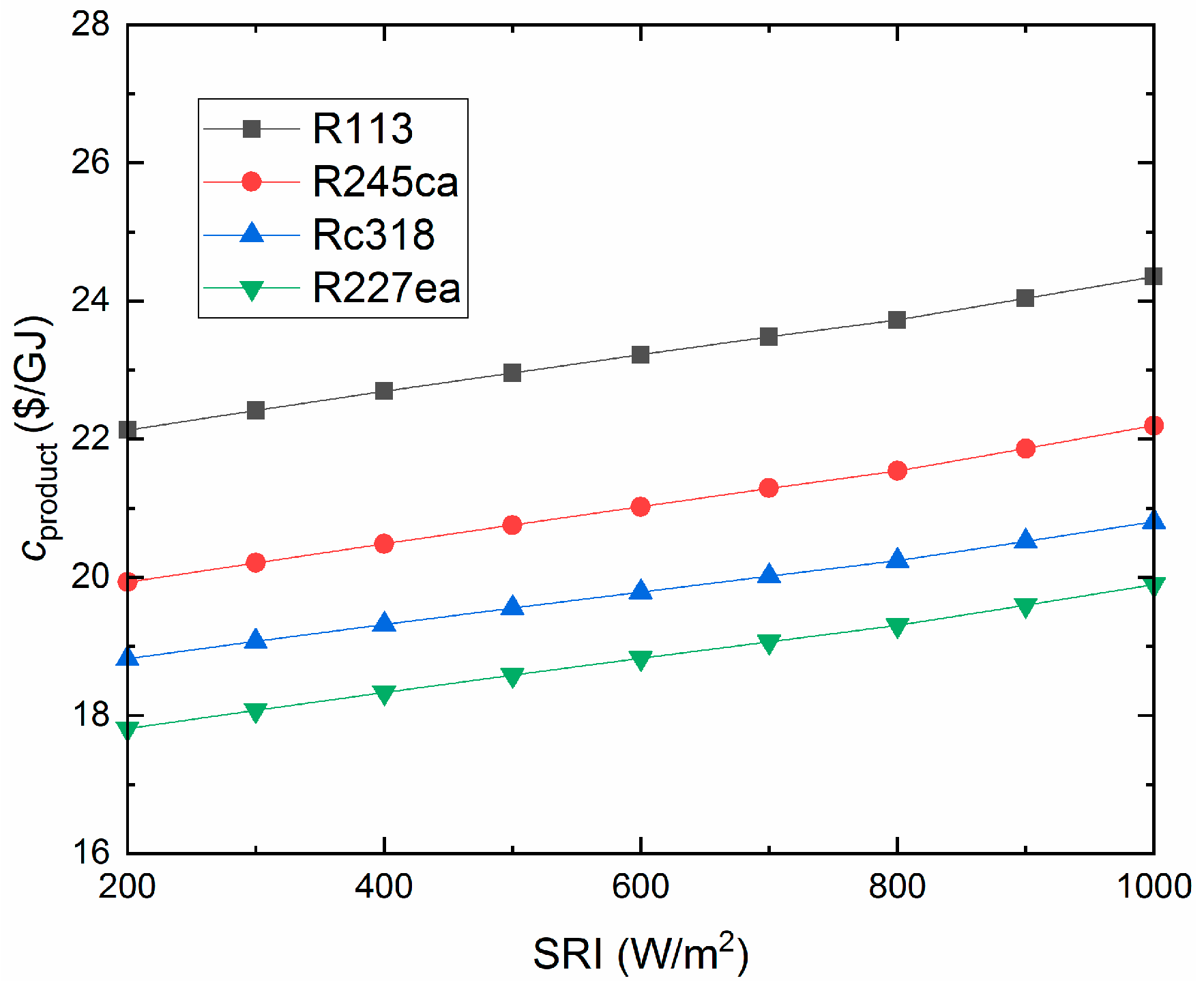
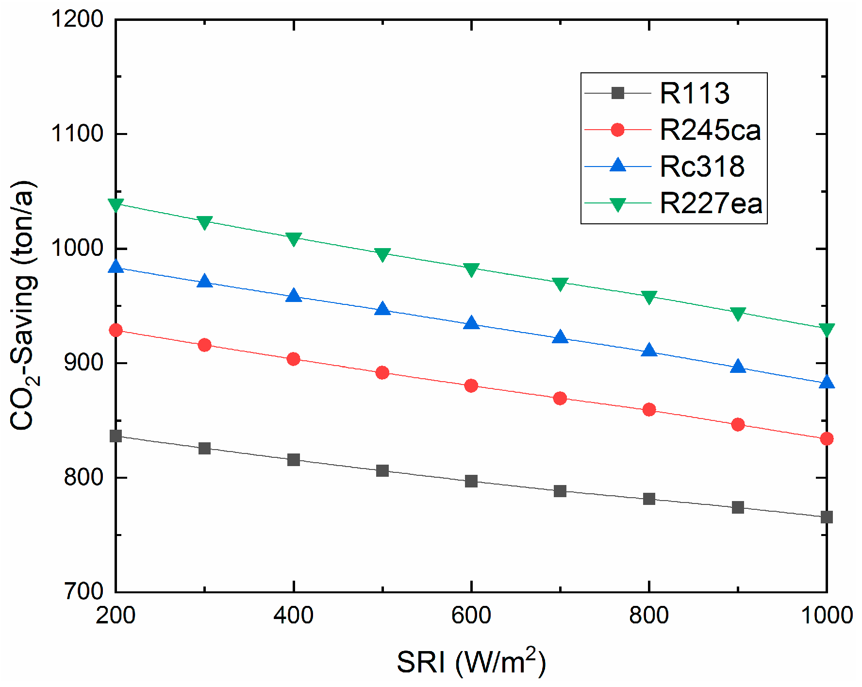
- (f)
- The unit cost of exergy for the product and the CO2-saving are decreased with the SRI. R227ea has the lowest production cost (19.3$/GJ, 800W/m2) and R227ea can save the largest amount of CO2 (958.7ton/a, 800W/m2).
Author Contributions
Funding
Acknowledgments
Conflicts of Interest
Nomenclature
| AC | Air Compressor |
| CC | Combustion Chamber |
| CCHP | Combined Cooling Heating and Power |
| CP | Condensate Preheater |
| DSG | Direct Steam Generation |
| DNI | Direct Normal Irradiance |
| Gen | Generator |
| GT | Gas Turbine |
| HEC | High Pressure Economizer |
| HEV | High Pressure Evaporator |
| HP | High Pressure |
| HPFWP | High Pressure Feed Water Pump |
| HRSG | Heat Recovery Steam Generator |
| HSH | High Pressure Superheater |
| HT | High Pressure Steam Turbine |
| HTF | Heat Transfer Fluid |
| IEC | Intermediate Pressure Economizer |
| IEV | Intermediate Pressure Evaporator |
| IP | Intermediate Pressure |
| IPFWP | Intermediate Pressure Feed Water Pump |
| ISCC | Integrated Solar Combined Cycle |
| ISH | Intermediate Pressure Superheater |
| IT | Intermediate Pressure Steam Turbine |
| LEV | Low Pressure Evaporator |
| LHV | Lower Heating Value |
| LP | Low Pressure |
| LPFWP | Low Pressure Feed Water Pump |
| LSH | Low Pressure Superheater |
| LT | Low Pressure Steam Turbine |
| NGCC | Natural Gas Combined Cycle |
| ORC | Organic Rankine Cycle |
| PTC | Parabolic Trough Collector |
| REH | Reheater |
| SRI | Solar radiation intensity |
| Exergy of a stream | |
| Physical exergy | |
| Chemical exergy | |
| Exergy received by the collector | |
| Exergy absorbed by the absorber | |
| Exergy destruction of kth component | |
| Fuel exergy of kth component | |
| Product exergy of kth component | |
| Energy received by the collector | |
| Energy absorbed by the absorber | |
| Incidence angle modifier | |
| Ambient temperature | |
| Solar surface temperature | |
| Collectors surface temperature | |
| Intercept factor | |
| Mirror reflectivity | |
| Glass transmissivity | |
| Solar absorptivity | |
| Clean factor | |
| Mirror utilization rate | |
| Exergy destruction rate |
References
- Naseri, A.; Bidi, M.; Ahmadi, M.H.; Saidur, R. Exergy analysis of a hydrogen and water production process by a solar-driven transcritical CO2 power cycle with Stirling engine. J. Clean. Prod. 2017, 158, 165–181. [Google Scholar] [CrossRef]
- Zhang, H.; Guan, X.; Ding, Y.; Liu, C. Emergy analysis of Organic Rankine Cycle (ORC) for waste heat power generation. J. Clean. Prod. 2018, 183, 1207–1215. [Google Scholar] [CrossRef]
- Chang, H.; Wan, Z.; Zheng, Y.; Chen, X.; Shu, S.; Tu, Z.; Chan, S.H. Energy analysis of a hybrid PEMFC–solar energy residential micro-CCHP system combined with an organic Rankine cycle and vapor compression cycle. Energy Convers. Manag. 2017, 142, 374–384. [Google Scholar] [CrossRef]
- Naseri, A.; Bidi, M.; Ahmadi, M.H. Thermodynamic and exergy analysis of a hydrogen and permeate water production process by a solar-driven transcritical CO2 power cycle with liquefied natural gas heat sink. Renew. Energy 2017, 113, 1215–1228. [Google Scholar] [CrossRef]
- Alqahtani, B.J.; Patiño-Echeverri, D. Integrated Solar Combined Cycle Power Plants: Paving the way for thermal solar. Appl. Energy 2016, 169, 927–936. [Google Scholar] [CrossRef]
- Aldali, Y.; Morad, K. Numerial simulation of the integrated solar/North Benghazi combined power plant. Appl. Therm. Eng. 2016, 108, 785–792. [Google Scholar] [CrossRef]
- Montes, M.J.; Abánades, A.; Martínez-Val, J.M.; Valdés, M. Solar multiple optimization for a solar-only thermal power plant, using oil as heat transfer fluid in the parabolic trough collectors. Sol. Energy 2009, 83, 2165–2176. [Google Scholar] [CrossRef]
- Esquivel-Patiño, G.G.; Serna-González, M.; Nápoles-Rivera, F. Thermal integration of natural gas combined cycle power plants with CO2 capture systems and organic Rankine cycles. Energy Convers. Manag. 2017, 151, 334–342. [Google Scholar] [CrossRef]
- Song, J.; Li, X.S.; Ren, X.D.; Gu, C.W. Performance analysis and parametric optimization of supercritical carbon dioxide (S-CO2) cycle with bottoming Organic Rankine Cycle (ORC). Energy 2018, 143, 406–416. [Google Scholar] [CrossRef]
- Katulić, S.; Čehil, M.; Schneider, D.R. Thermodynamic efficiency improvement of combined cycle power plant’s bottom cycle based on organic working fluids. Energy 2018, 147, 36–50. [Google Scholar]
- Shaaban, S. Analysis of an integrated solar combined cycle with steam and organic Rankine cycles as bottoming cycles. Energy Convers. Manag. 2016, 126, 1003–1012. [Google Scholar] [CrossRef]
- Chowdhury, J.; Nguyen, B.; Thornhill, D.; Hu, Y.; Soulatiantork, P.; Balta-Ozkan, N.; Varga, L. Fuzzy Nonlinear Dynamic Evaporator Model in Supercritical Organic Rankine Cycle Waste Heat Recovery Systems. Energies 2018, 11, 901. [Google Scholar] [CrossRef]
- Singh, H.; Mishra, R.S. Performance analysis of solar parabolic trough collectors driven combined supercritical CO2 and organic Rankine cycle. Eng. Sci. Technol. Int. J. 2018, 21, 451–464. [Google Scholar] [CrossRef]
- Spayde, E.; Mago, P.J.; Luck, R. Economic, Energetic, and Environmental Performance of a Solar Powered Organic Rankine Cycle with Electric Energy Storage in Different Commercial Buildings. Energies 2018, 11, 276. [Google Scholar] [CrossRef]
- Algieri, A.; Morrone, P. Techno-economic Analysis of Biomass-fired ORC Systems for Single-family Combined Heat and Power (CHP) Applications. Energy Procedia 2014, 45, 1285–1294. [Google Scholar] [CrossRef]
- Fang, F.; Wei, L.; Liu, J.; Zhang, J.; Hou, G. Complementary configuration and operation of a CCHP-ORC system. Energy 2012, 46, 211–220. [Google Scholar] [CrossRef]
- Ebrahimi, M.; Ahookhosh, K. Integrated energy–exergy optimization of a novel micro-CCHP cycle based on MGT–ORC and steam ejector refrigerator. Appl. Therm. Eng. 2016, 102, 1206–1218. [Google Scholar] [CrossRef]
- Ashouri, M.; Ahmadi, M.; Pourkiaei, S.; Astaraei, F.; Ghasempour, R.; Ming, T.; Hemati, J. Exergy and Exergo-economic Analysis and Optimization of a Solar Double Pressure Organic Rankine Cycle. Therm. Sci. Eng. Prog. 2018, 6, 72–86. [Google Scholar] [CrossRef]
- Wang, S.; Fu, Z.; Sajid, S.; Zhang, T.; Zhang, G. Thermodynamic and Economic Analysis of an Integrated Solar Combined Cycle System. Entropy 2018, 20, 313. [Google Scholar] [CrossRef]
- Bailek, N.; Bouchouicha, K.; Aoun, N.; EL-Shimy, M.; Jamil, B.; Mostafaeipour, A. Optimized Fixed Tilt for Incident Solar Energy Maximization on Flat Surfaces Located in the Algerian Big South. Sustain. Energy Technol. Assess. 2018, 28, 96–102. [Google Scholar] [CrossRef]
- Bellos, E.; Tzivanidis, C. A detailed exergetic analysis of parabolic trough collectors. Energy Convers. Manag. 2017, 149, 275–292. [Google Scholar] [CrossRef]
- Boyaghchi, F.A.; Molaie, H. Advanced exergy and environmental analyses and multi objective optimization of a real combined cycle power plant with supplementary firing using evolutionary algorithm. Energy 2015, 93, 2267–2279. [Google Scholar] [CrossRef]
- Adibhatla, S.; Kaushik, S.C. Energy, exergy and economic (3E) analysis of integrated solar direct steam generation combined cycle power plant. Sustain. Energy Technol. Assess. 2017, 20, 88–97. [Google Scholar] [CrossRef]
- Wang, S.; Fu, Z. Thermodynamic and economic analysis of solar assisted CCHP-ORC system with DME as fuel. Energy Convers. Manag. 2019, 186, 535–545. [Google Scholar] [CrossRef]
- Fani, M.; Sadreddin, A. Solar assisted CCHP system, energetic, economic and environmental analysis, case study: Educational office buildings. Energy Build. 2017, 136, 100–109. [Google Scholar] [CrossRef]
- Luo, D.; Mahmoud, A.; Cogswell, F. Evaluation of low-GWP fluids for power generation with organic Rankine cycle. Energy 2015, 85, 481–488. [Google Scholar] [CrossRef]
- Monammadzadeh Bina, S.; Jalilinasrabady, S.; Fujii, H. Thermo-economic evaluation of various bottoming ORCs for geothermal power plant, determination of optimum cycle for Sabalan power plant exhaust. Geothermics 2017, 70, 181–191. [Google Scholar] [CrossRef]
- Liu, C.; Gao, T. Off-design performance analysis of basic ORC, ORC using zeotropic mixtures and composition-adjustable ORC under optimal control strategy. Energy 2019, 171, 95–108. [Google Scholar] [CrossRef]
- EI-Emam, R.S.; Dincer, I. Exergy and exergoeconomic analyses and optimization of geothermal organic Rankine cycle. Appl. Therm. Eng. 2013, 59, 435–444. [Google Scholar] [CrossRef]
- Mosaffa, A.H.; Garousi Farshi, L.; Infante Ferreira, C.A.; Rosen, M.A. Exergocconomic and environmental analyses of CO2/NH3 cascade refrigeration systems equipped with different types of flash tank intercoolers. Energy Convers. Manag. 2016, 59, 442–453. [Google Scholar] [CrossRef]
- Heberle, F.; Schifflechner, C.; Bruggemann, D. Life cycle assessment of Organic Rankine Cycles for geothermal power generation condidering low-GWP working fluis. Geothermics 2016, 64, 392–400. [Google Scholar] [CrossRef]


| Parameters | Siemens | Simulation | Units |
|---|---|---|---|
| Capacity | 390 | 390 | MW |
| Main steam Reheated steam Low-pressure steam | 12.5/566/72.6 2.99/551/85.6 0.45/239/12.3 | 12.6/567/73.8 2.91/551/86.7 0.46/239.9/12.9 | MPa/°C/kg·s−1 MPa/°C/kg·s−1 MPa/°C/kg·s−1 |
| Gas turbine exhaust Ambient temperature | 590/643 20 | 590.6/646 20 | °C/kg·s−1 °C |
| Exhaust gas temperature | 91 | 90.9 | °C |
| Parameters | Values | Ref. |
|---|---|---|
| Width | 5.76 m | [13] |
| Length | 150 m | - |
| Number of collectors | 280 | - |
| Temperature of feed water | 149.5 °C | |
| Temperature of superheated steam | 358.5 °C | - |
| Intercept factor | 0.92 | [7,23] |
| Mirror reflectivity | 0.92 | [7,23] |
| Glass transmissivity | 0.945 | [7,23] |
| Solar absorptivity | 0.94 | [7,23] |
| Clean factor | 0.95 | [7,23] |
| Mirror utilization rate | 0.91 | - |
| Inlet/outlet temperature of HTF | 315.9 °C/395.0 °C | - |
| Inlet/outlet pressure of HTF | 5.0 MPa/3.5 MPa | - |
| Heat loss of pipeline | 20 W/m2 | [24] |
| Thermal energy storage capacity | 40 L/kW∙h | [25] |
| Parameters | Value | Unit |
|---|---|---|
| Exhaust gas temperature | 91 | °C |
| Exhaust gas mass flow rate | 640 | kg/s |
| Cooling water temperature | 20 | °C |
| Isentropic efficiency of turbine | 87 [13] | % |
| Isentropic efficiency of pump | 85 [13] | % |
| Pump discharge pressure | 2.5 | MPa |
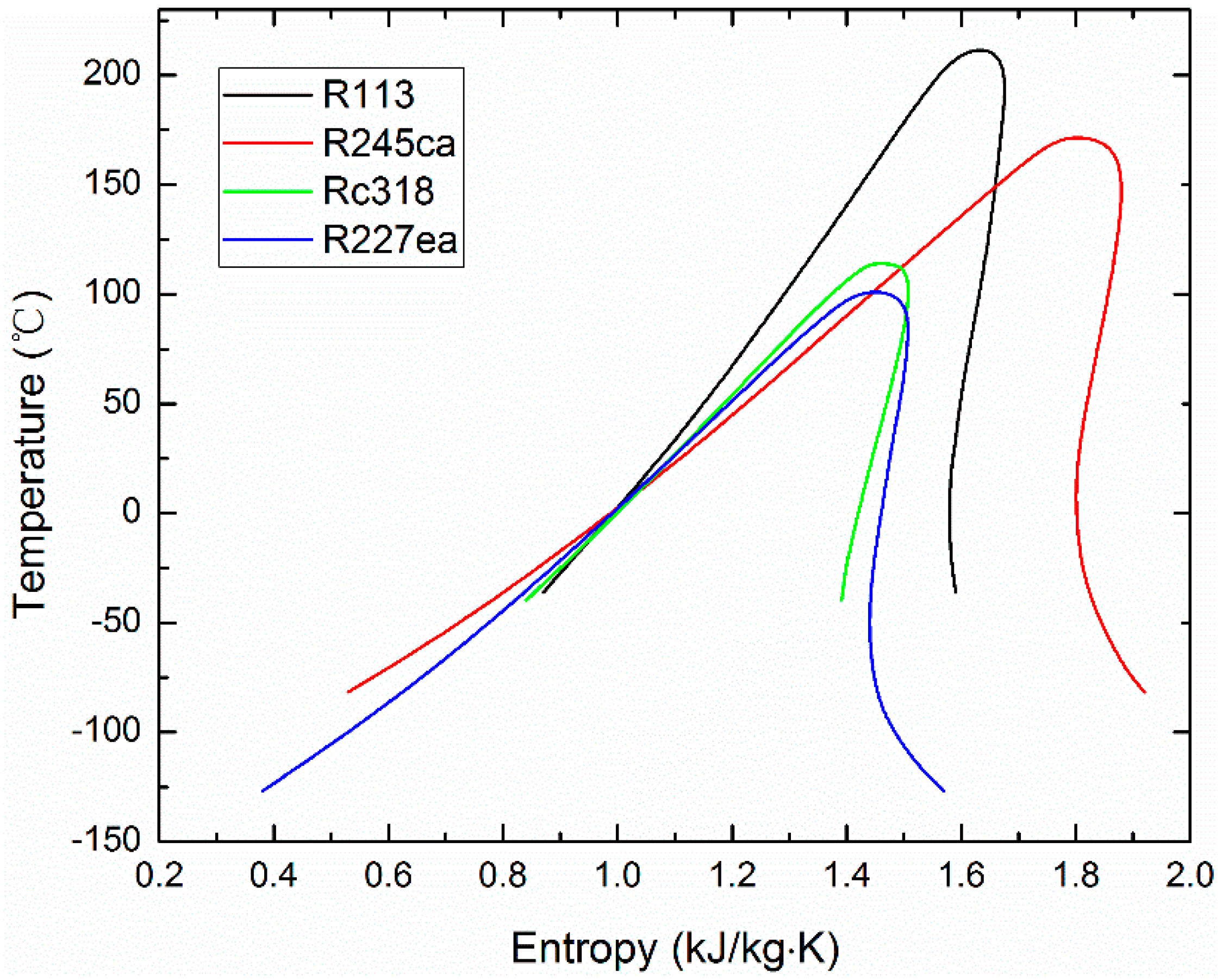
| Working Fluid | Boiling Point (°C) | Critical Temperature (°C) | Critical Pressure (MPa) | ODP | GWP | ASHRAE | Ref. |
|---|---|---|---|---|---|---|---|
| R113 | 47.59 | 214.06 | 3.39 | 0.9 | 5330 | A1 | [26] |
| R245ca | 25.13 | 174.42 | 3.93 | 0 | 640 | - | [26] |
| Rc318 | −5.98 | 115.23 | 2.78 | 0 | 8700 | A1 | [26] |
| R227ea | −16.45 | 101.65 | 2.93 | 0 | 3500 | A1 | [26] |
© 2019 by the authors. Licensee MDPI, Basel, Switzerland. This article is an open access article distributed under the terms and conditions of the Creative Commons Attribution (CC BY) license (http://creativecommons.org/licenses/by/4.0/).
Share and Cite
Wang, S.; Fu, Z. Thermodynamic Investigation of an Integrated Solar Combined Cycle with an ORC System. Entropy 2019, 21, 428. https://doi.org/10.3390/e21040428
Wang S, Fu Z. Thermodynamic Investigation of an Integrated Solar Combined Cycle with an ORC System. Entropy. 2019; 21(4):428. https://doi.org/10.3390/e21040428
Chicago/Turabian StyleWang, Shucheng, and Zhongguang Fu. 2019. "Thermodynamic Investigation of an Integrated Solar Combined Cycle with an ORC System" Entropy 21, no. 4: 428. https://doi.org/10.3390/e21040428
APA StyleWang, S., & Fu, Z. (2019). Thermodynamic Investigation of an Integrated Solar Combined Cycle with an ORC System. Entropy, 21(4), 428. https://doi.org/10.3390/e21040428