Identification of Multiple Faults in Gearbox Based on Multipoint Optional Minimum Entropy Deconvolution Adjusted and Permutation Entropy


Abstract
:1. Introduction
2. The Multipoint Optimal Minimum Entropy Deconvolution Adjustment
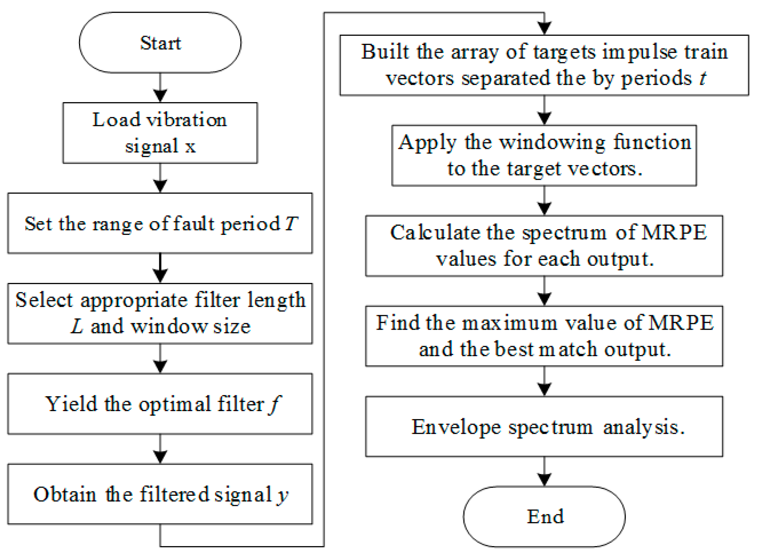
- Step 1: Loading the raw vibration signal, , measured by an accelerometer and the range of the fault period, .
- Step 2: Selecting the appropriate filter length, , and window size.
- Step 3: Calculating , and from the signal, . Yielding the optimal filter from Equation (3). Obtaining the filtered signal, , from Equation (6).
- Step 4: Building an array of target impulse train vectors, separated by the periods, .
- Step 5: Applying the window function to the target vectors.
- Step 6: Calculating the spectrum of outputs.
- Step 7: Calculating the spectrum of MKurt values for each output.
- Step 8: Finding the maximum value of MKurt and the best match output.
- Step 9: Enveloping the spectrum analysis.
3. The Proposed Method for The Gearbox Fault Diagnosis
3.1. Basic Principle of Permutation Entropy
3.2. Multipoint Reciprocal Permutation Entropy
4. Simulations
5. Experimental Analysis
6. Conclusions
- The diagnoses of weak impact faults in complex faults were achieved using MOMEDA combined with a spectrum analysis.
- The MKurt-MOMEDA and MRPE-MOMEDA were able to identify the multi-faults of rotating machinery using simulation and experimental analysis.
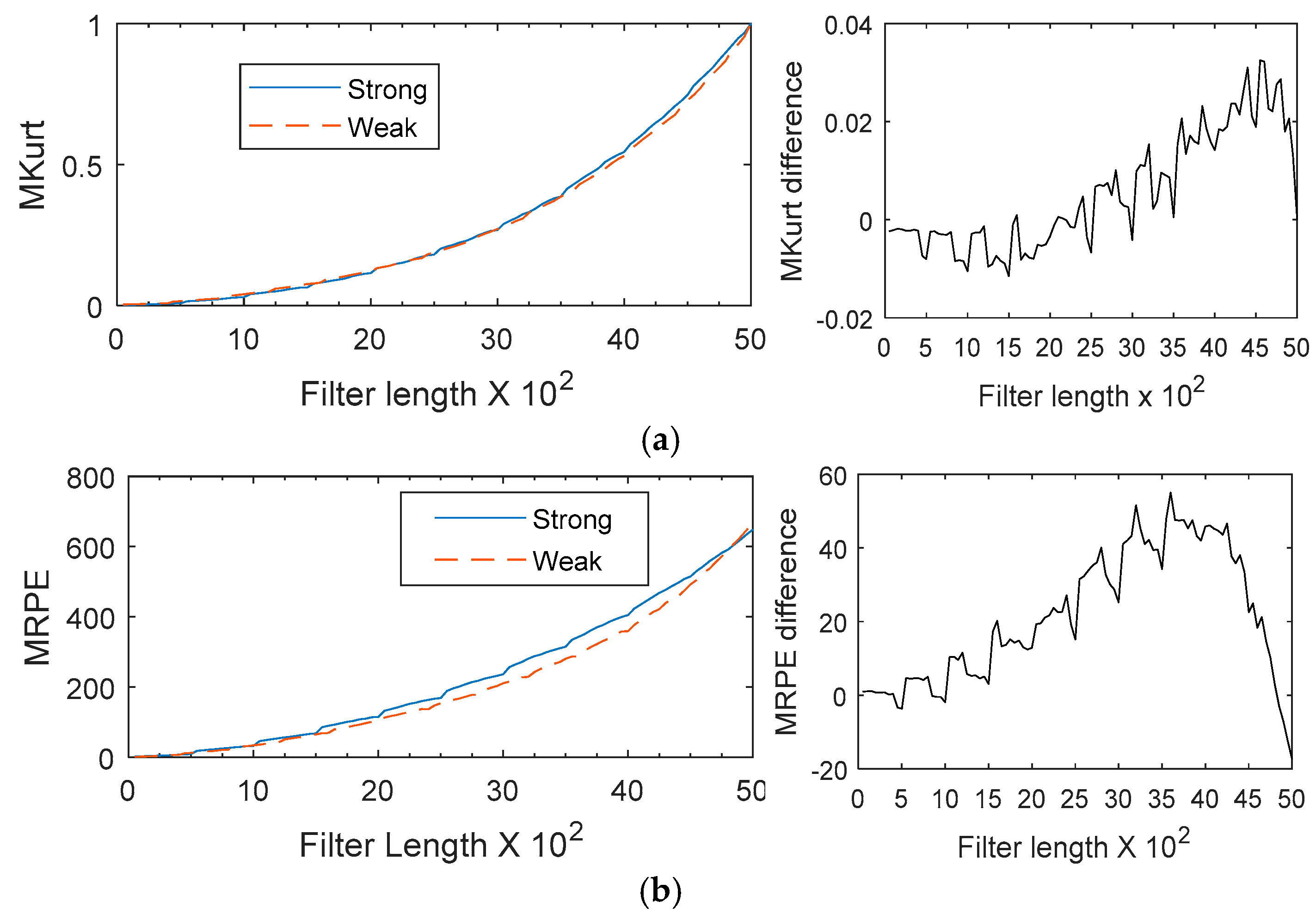
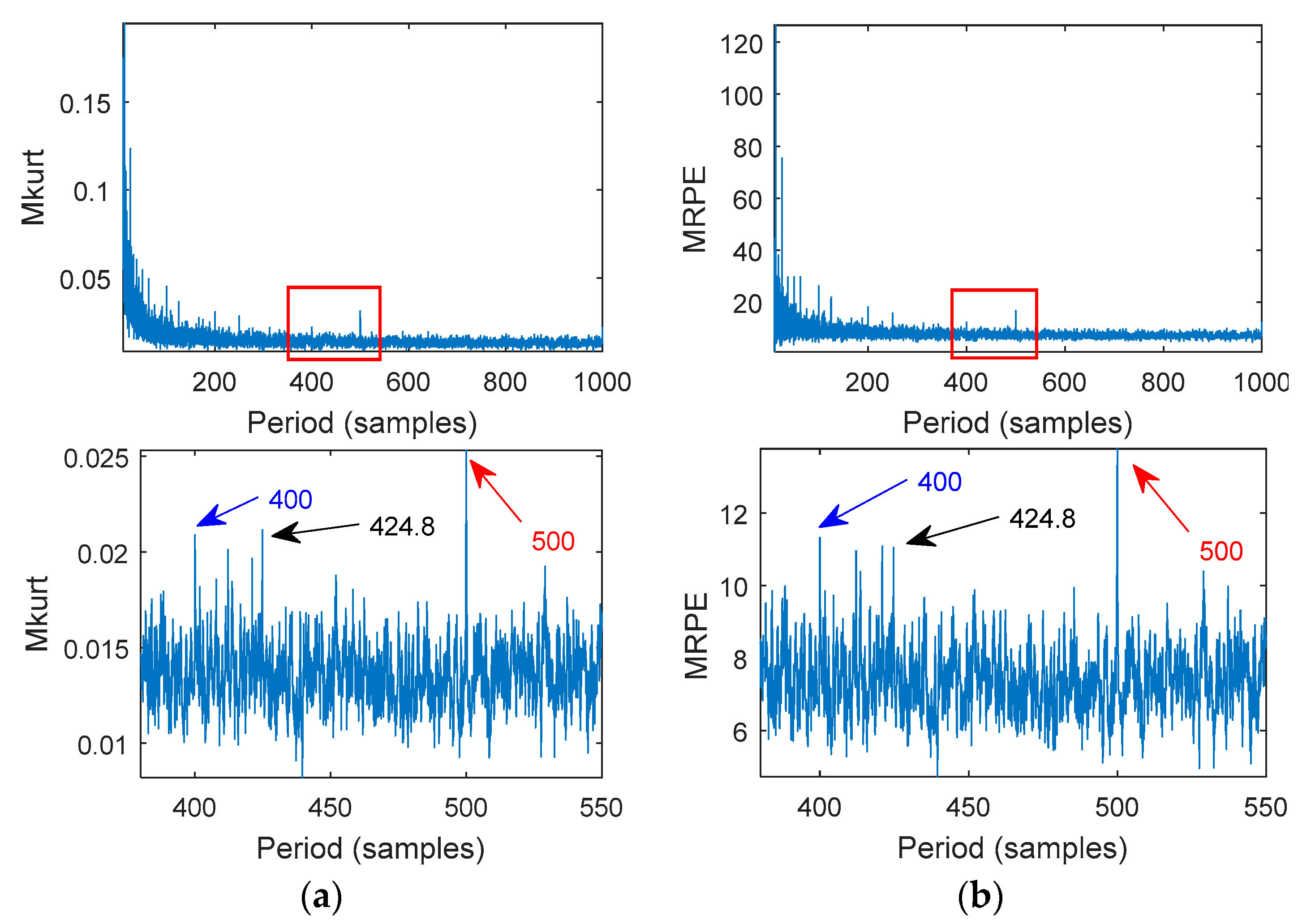
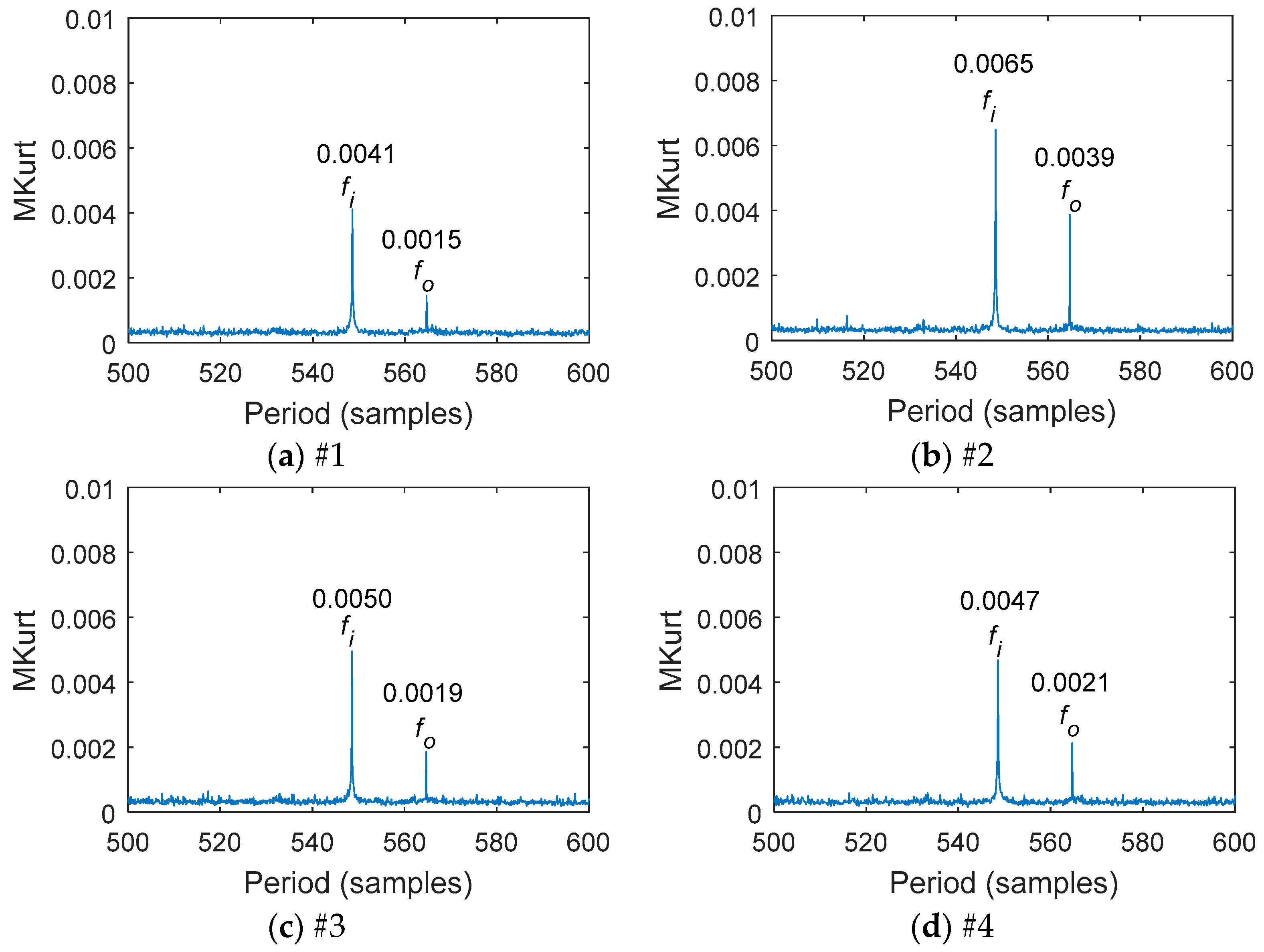
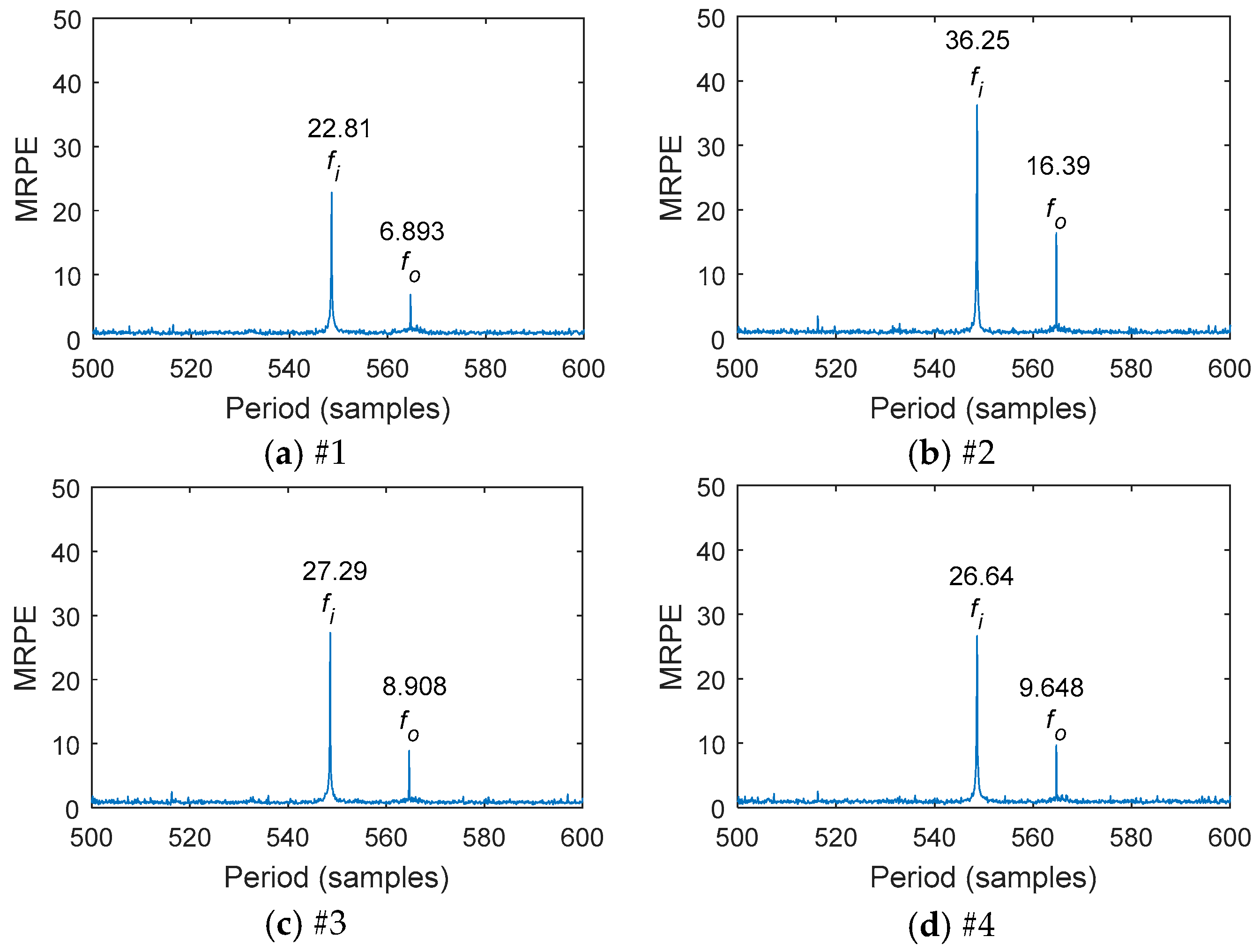
- A comparison of the fault indication between MKurt-MOMEDA and MRPE-MOMEDA was investigated. Compared to MKurt, MRPE had an excellent tracking ability of the sources of impact faults under the same fault conditions. The MRPE values of the different points were greater. The difference of the MKurt values among the different points was small.
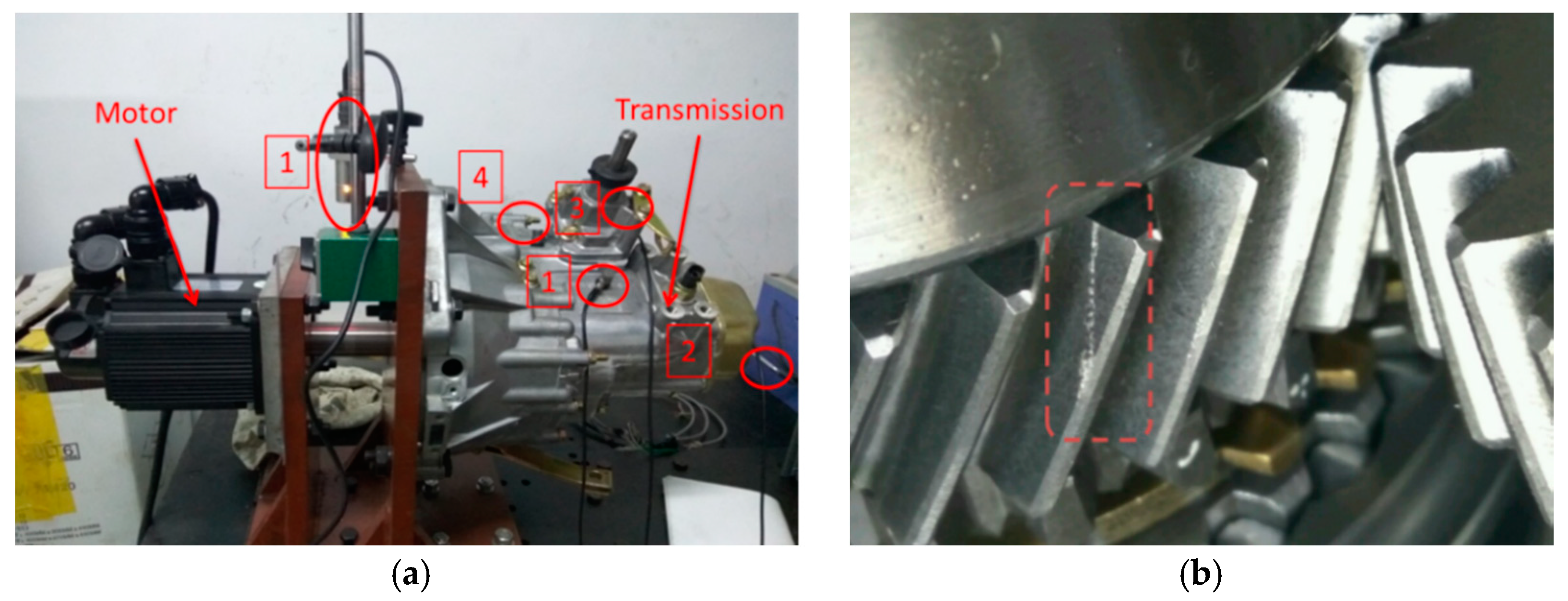
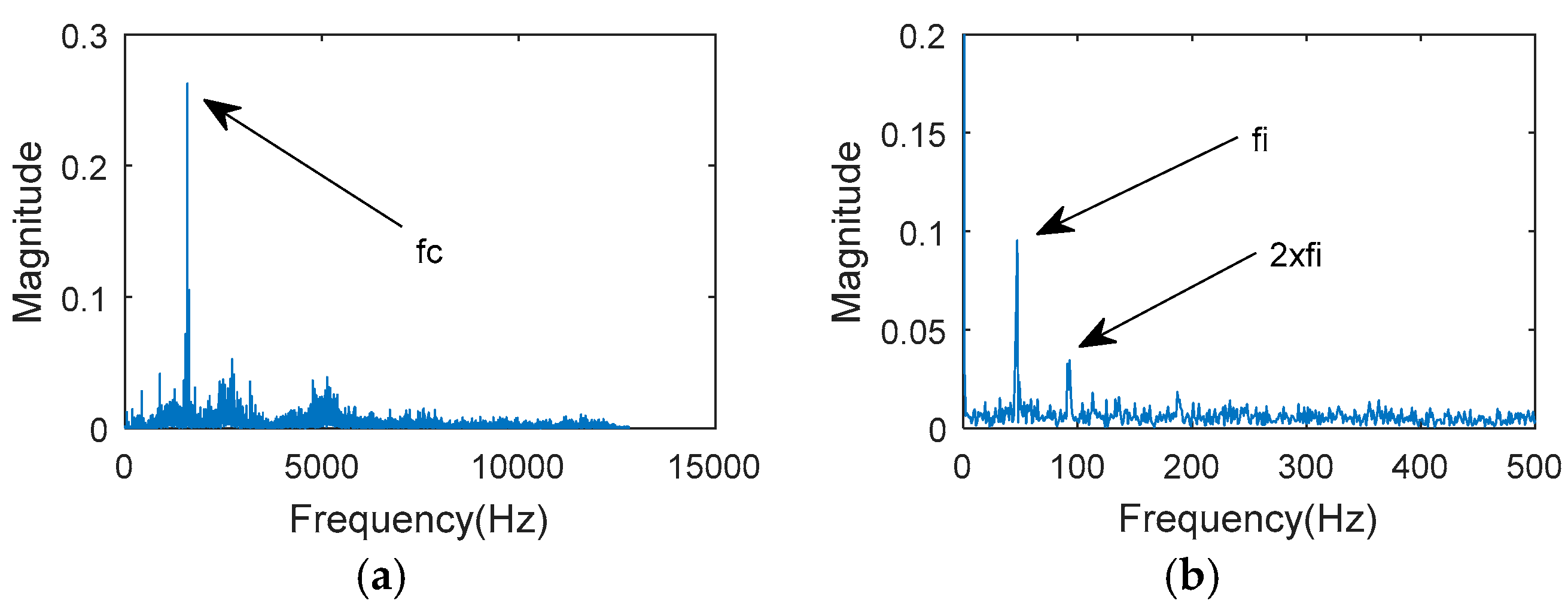
- The impact fault frequencies of 46.7 Hz and 45.3 Hz were extracted from the transmission vibration signal by MRPE-MOMEDA.
- Weak feature extraction in composite faults was difficult. There were fewer test failure samples and more different types of faults need to be further verified in the future.
Author Contributions
Acknowledgments
Conflicts of Interest
Abbreviations
| MOMEDA | Multipoint Optional Minimum Entropy Deconvolution Adjusted |
| MKurt | Multipoint Kurtosis |
| MPE | Multipoint Permutation Entropy |
| MRPE | Multipoint Reciprocal Permutation Entropy |
| SampEn | Sample Entropy |
| FIR | Finite Impulse Response |
| FFT | Fast Fourier Transformation |
References
- Lin, J.; Chen, Q. In application of the EEMD method to multiple faults diagnosis of gearbox. In Proceedings of the 2nd International Conference on Advanced Computer Control, Shenyang, China, 27–29 March 2010; pp. 395–399. [Google Scholar]
- Wang, Z.J.; Han, Z.N.; Ning, S.H.; Liang, P.W. Wind turbine gearbox multi-fault diagnosis based on CMF-EEMD. Electr. Mach. Control 2016, 2016, 104–111. (In Chinese) [Google Scholar]
- Li, Z.; Yan, X.; Yuan, C.; Peng, Z.; Li, L. Virtual prototype and experimental research on gear multi-fault diagnosis using wavelet-autoregressive model and principal component analysis method. Mech. Syst. Signal Process. 2011, 25, 2589–2607. [Google Scholar] [CrossRef]
- Mark, W.D.; Reagor, C.P. Static-transmission-error vibratory-excitation contributions from plastically deformed gear teeth caused by tooth bending-fatigue damage. Mech. Syst. Signal Process. 2007, 21, 885–905. [Google Scholar] [CrossRef]
- Litak, G.; Friswell, M.I. Dynamics of a gear system with faults in meshing stiffness. Nonlinear Dynam. 2005, 41, 415–421. [Google Scholar] [CrossRef]
- Pacheco, F.; Cerrada, M.; Cabrera, D.; Li, C.; Zurita, G. A statistical comparison of neuroclassifiers and feature selection methods for gearbox fault diagnosis under realistic conditions. Neurocomputing 2016, 194, 192–206. [Google Scholar] [CrossRef]
- Nissilä, J. Local regularity analysis with wavelet transform in gear tooth failure detection. Manag. Syst. Prod. Eng. 2017, 25, 176–182. [Google Scholar] [CrossRef]
- Wiggins, R.A. Minimum entropy deconvolution. Geoexploration 1980, 16, 21–35. [Google Scholar] [CrossRef]
- Endo, H.; Randall, R.B. Enhancement of autoregressive model based gear tooth fault detection technique by the use of minimum entropy deconvolution filter. Mech. Syst. Signal Process. 2007, 21, 906–919. [Google Scholar] [CrossRef]
- He, D.; Wang, X.; Li, S.; Lin, J.; Zhao, M. Identification of multiple faults in rotating machinery based on minimum entropy deconvolution combined with spectral kurtosis. Mech. Syst. Signal Process. 2016, 81, 235–249. [Google Scholar] [CrossRef]
- Mcdonald, G.L.; Zhao, Q.; Zuo, M.J. Maximum correlated Kurtosis deconvolution and application on gear tooth chip fault detection. Mech. Syst. Signal Process. 2012, 33, 237–255. [Google Scholar] [CrossRef]
- Li, G.; Zhao, Q. Minimum entropy deconvolution optimized sinusoidal synthesis and its application to vibration based fault detection. J. Sound Vib. 2017, 390, 218–231. [Google Scholar] [CrossRef]
- Mcdonald, G.L.; Zhao, Q. Multipoint optimal minimum entropy deconvolution and convolution fix: Application to vibration fault detection. Mech. Syst. Signal Process. 2016, 82, 461–477. [Google Scholar] [CrossRef]
- Yan, R.; Gao, R.X. Approximate entropy as a diagnostic tool for machine health monitoring. Mech. Syst. Signal Process. 2007, 21, 824–839. [Google Scholar] [CrossRef]
- Han, M.; Pan, J. A fault diagnosis method combined with LMD, sample entropy and energy ratio for roller bearings. Measurement 2015, 76, 7–19. [Google Scholar] [CrossRef]
- Pan, Y.N.; Chen, J.; Li, X.L. Spectral entropy: A complementary index for rolling element bearing performance degradation assessment. Proc. Inst. Mech. Eng. Pt. C J. Mechan. 2009, 223, 1223–1231. [Google Scholar] [CrossRef]
- Hao, R.; Feng, Z.; Chu, F. Application of support vector machine based on pattern spectrum entropy in fault diagnostics of bearings. In Proceedings of the Prognostics and System Health Management Conference, Macao, China, 12–14 January 2010. [Google Scholar]
- Bandt, C.; Pompe, B. Permutation entropy: A natural complexity measure for time series. Phys. Rev. Lett. 2002, 88, 174102. [Google Scholar] [CrossRef] [PubMed]
- Wu, S.D.; Wu, P.H.; Wu, C.W.; Ding, J.J.; Wang, C.C. Bearing fault diagnosis based on multiscale permutation entropy and support vector machine. Entropy 2012, 14, 2650–2654. [Google Scholar] [CrossRef]
- Shi, Z.; Song, W.; Taheri, S. Improved LMD, permutation entropy and optimized K-means to fault diagnosis for roller bearings. Entropy 2016, 18, 70. [Google Scholar] [CrossRef]
- Fadlallah, B.; Chen, B.; Keil, A.; Príncipe, J. Weighted-permutation entropy: A complexity measure for time series incorporating amplitude information. Phys. Rev. E Stat. Nonlin. Soft Matter Phys. 2013, 87, 022911. [Google Scholar] [CrossRef] [PubMed]
- Yan, R.; Liu, Y.; Gao, R.X. Permutation entropy: A nonlinear statistical measure for status characterization of rotary machines. Mech. Syst. Signal Process. 2012, 29, 474–484. [Google Scholar] [CrossRef]
- Liu, B.; Riemenschneider, S.; Xu, Y. Gearbox fault diagnosis using empirical mode decomposition and hilbert spectrum. Mech. Syst. Signal Process. 2006, 20, 718–734. [Google Scholar] [CrossRef]


| Parameter | The 4th Gear Pair | Constantly Meshed Gear Pair | ||
|---|---|---|---|---|
| Drive Wheel | Driven Wheel | Drive Wheel | Driven Wheel | |
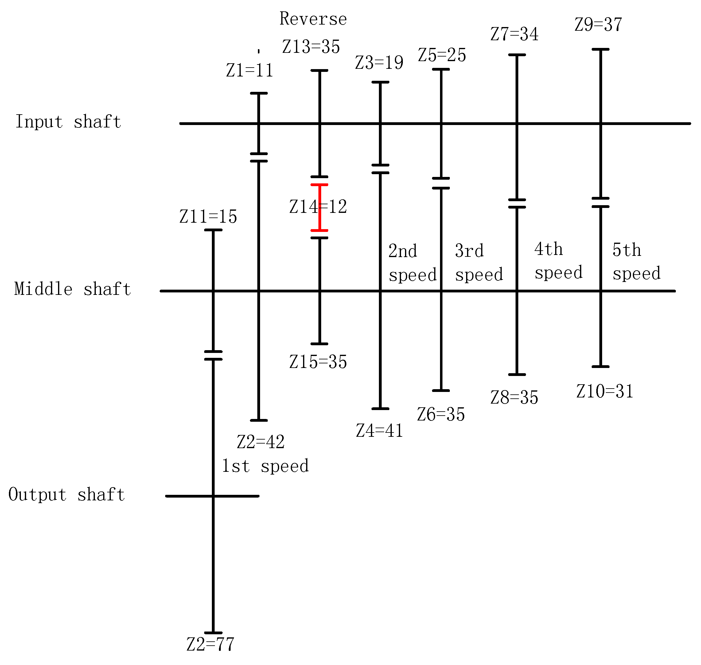
| Gear number | 34 | 35 | 15 | 77 |
| Rotational frequency (Hz) | 46.7 | 45.3 | 45.3 | 8.8 |
| Mesh frequency (Hz) | 1586.7 | 679.5 | ||
| Position | foc | fbc | fc | fic |
|---|---|---|---|---|
| Input shaft | 2.504 | 1.616 | 0.358 | 4.494 |
| 3.454 | 2.036 | 0.384 | 5.544 | |
| Middle shaft | 7.32 | 3.324 | 0.3792 | 11.0808 |
| 6.61 | 2.9742 | 0.3792 | 9.914 | |
| Output shaft | 0.891 | 0.576 | 0.081 | 1.2398 |
| 0.6748 | 0.435 | 0.075 | 1.0282 |
| Data | Speed (r/min) | Sample Rate (k/s) | Frequency/Hz | Samples |
|---|---|---|---|---|
| 1 | 2800 | 25.6 | 46.7 | 548.2 |
| 2 | 2800 | 25.6 | 45.4 | 563.8 |
© 2018 by the authors. Licensee MDPI, Basel, Switzerland. This article is an open access article distributed under the terms and conditions of the Creative Commons Attribution (CC BY) license (http://creativecommons.org/licenses/by/4.0/).
Share and Cite
Sun, H.; Wu, C.; Liang, X.; Zeng, Q. Identification of Multiple Faults in Gearbox Based on Multipoint Optional Minimum Entropy Deconvolution Adjusted and Permutation Entropy. Entropy 2018, 20, 850. https://doi.org/10.3390/e20110850
Sun H, Wu C, Liang X, Zeng Q. Identification of Multiple Faults in Gearbox Based on Multipoint Optional Minimum Entropy Deconvolution Adjusted and Permutation Entropy. Entropy. 2018; 20(11):850. https://doi.org/10.3390/e20110850
Chicago/Turabian StyleSun, Huer, Chao Wu, Xiaohua Liang, and Qunfeng Zeng. 2018. "Identification of Multiple Faults in Gearbox Based on Multipoint Optional Minimum Entropy Deconvolution Adjusted and Permutation Entropy" Entropy 20, no. 11: 850. https://doi.org/10.3390/e20110850
APA StyleSun, H., Wu, C., Liang, X., & Zeng, Q. (2018). Identification of Multiple Faults in Gearbox Based on Multipoint Optional Minimum Entropy Deconvolution Adjusted and Permutation Entropy. Entropy, 20(11), 850. https://doi.org/10.3390/e20110850