Article

Limits and Optimization of Power Input or Output of Actual Thermal Cycles

Department of Mechanical and Manufacturing Engineering, Engineering Faculty, Bilecik S.E. University, Bilecik 11210, Turkey
*
Author to whom correspondence should be addressed.
Entropy 2013, 15(8), 3219-3248; https://doi.org/10.3390/e15083309
Submission received: 24 April 2013 / Revised: 24 June 2013 / Accepted: 6 August 2013 / Published: 12 August 2013

Abstract

:
In classical thermodynamic, maximum power obtained from system (or minimum power supplied to system) defined as availability (exergy), but availability term is only used for reversible systems. In reality, there is no reversible system, all systems are irreversible, because reversible cycles doesn’t include constrains like time or size and they operates in quasi-equilibrium state. Purpose of this study is to define limits of the all basic thermodynamic cycles and to provide finite-time exergy models for irreversible cycles and to obtain the maximum (or minimum) available power for irreversible (finite-time exergy) cycles. In this study, available power optimization and performance limits were defined all basic irreversible thermodynamic cycles, by using first and second law of thermodynamic. Finally, these results were evaluated in terms of cycles’ first and second law efficiency, COP, power output (or input) and exergy destruction.

1. Introduction

In classical thermodynamics, availability (or exergy) is used for defining maximum power that can be obtained from the system. However, classical thermodynamics doesn’t consider constraints causing irreversibility, it uses for reversible systems only. Unlike reversible processes, actual processes generate entropy. Entropy generation are resulted from external irreversibilities, which are caused by the heat transfer through finite temperature difference, and internal irreversibilities, which are caused by friction etc. For improving more efficient and providing environmentally less harmless thermodynamic cycles, one must effort to decrease entropy generation while maximizing work output. Finite-time thermodynamic can enable us to more realistic thermal cycles [1,2,3]. In order to obtain the most efficient thermodynamic cycles finite-time exergy approach must be evaluate for the engineers and scientists. In this study, methods were described to find out optimum (or critical) point for all cycles. These methods include to determine maximum available work output for the power generation cycles and minimum available work input for the heat pump and refrigeration cycles. In the literature, there are many theoretical researches about finite time exergy, but no for the application of the thermal cycles [4,5,6,7,8,9,10,11,12,13,14,15,16,17,18,19,20,21,22,23,24,25,26,27].

2. Thermodynamic Analysis

In this section, generalized availability function at Equation (1) [6] was applied to all basic thermal cycles separating as two parts:
(i)
Power cycles.
(ii)
Heat pump and refrigeration cycles.
Entropy 15 03219 i001
Equation (1) submitted by Sienutcyz and Spakovsky [6] consists of available work output (exergy output) and entropy production (exergy destruction). This Equation could be applied for thermodynamic cycles. Optimization parameters selected as non-dimensional compression parameter for SI, CI, Stirling cycles and non-dimensional pressure parameter for irreversible Brayton and Ericsson cycles. Compression and pressure ratios are most important design parameters for gas power cycles. Because these parameters affects directly of system’s temperatures and pressures among the cycle process. Evaporator and condenser temperatures are main parameters for Rankine, heat pump and refrigerator cycles. Design parameters were investigated detail at following sections.
Assumptions made for cycles are as follows:
  • Assumptions are listed for the cycles.
  • For irreversible Rankine, heat pump and refrigeration cycles.
  • All processes are irreversible.
  • Systems follow a continuous pattern.
  • Heat exchangers’ dimensions are limited and convection coefficients are constant.
For irreversible SI, CI, Stirling—Ericsson and Brayton cycles:
  • All processes are irreversible.
  • Specific heats are constant and average specific heats are used.
  • Piston friction is neglected.
  • Powering fluid is air, which is the ideal gas.
  • Polytrophic coefficients are constant and an average polytrophic coefficient is identified for each cycle.
Internal irreversibility parameter is more than one ( I > 1) for all cycles. Environmental temperature (To) is accepted as 298.15 K for all cycles. Other assessment criteria using this study except for finite-time exergy output (or input) can be defined as following: Fist law efficiency:
Entropy 15 03219 i002
Exergy destruction:
Entropy 15 03219 i003
Second law efficiency:
Entropy 15 03219 i004

2.1. Power Generation Cycles

In this section, thermodynamic cycles that produce power will be examined in detail. Effects of obtained optimization values were presented in the results.

2.1.1. Thermodynamic Analysis of Irreversible Rankine Cycle

Recently, Rankine cycle has gained importance thanks to an increase in the search for new energy technologies and more efficient systems, because this cycle can generate power with organic powering fluids that enable the use of energy sources at low temperatures. In addition to this, facilities which power with a conventional Rankine cycle that uses coal as fuel and bottom cycle of the cogeneration systems are still widely used. Emissions that are sent out by these facilities to the environment because of the global warming and entropy production must be reduced to a minimum for the more efficient cycles. In Figure 1, the T-s diagram of an irreversible Rankine cycle is seen.
Figure 1. T-s (temperature-entropy) diagram of irreversible Rankine cycle (TH = high temperature, TL = low temperature).
Entropy 15 03219 g001
From the first law of thermodynamics:
Entropy 15 03219 i005
where, W ˙ n e t , R (power output), Q ˙ H , R (added heat) and Q ˙ L , R (rejected heat). Added and rejected heat can be defined as:
Entropy 15 03219 i006
where, ϕ (the heat conductance) and TH (the combustion temperature).
From the second law of thermodynamics:
Entropy 15 03219 i007
where, I R ( internal irreversibility parameter for Rankine cycle). Entropy generation is:
Entropy 15 03219 i008
A ˙ R (available work output of the Rankine cycle) can be obtained from the Equations (1) and (5)–(8):
Entropy 15 03219 i009
As seen at Figure 5 Rankine cycle has an optimum point maximizing available work output. The derivative of the Rankine cycle’s available work output (finite time-exergy) function according to the evaporator temperature is equalized to zero ( A ˙ R T E , R = 0 ) and optimum temperatures can be seen as follow:
Entropy 15 03219 i010
Unlike evaporator temperature, as seen Figure 7, condenser temperature has linear effects on the available work output and has not an optimum point. However, linear change Equation of the available work output with condenser temperature can be defined with regression:
Entropy 15 03219 i011
where, R2 is the coefficient of determination for the regression.

2.1.2. Thermodynamic Analysis of Irreversible Spark Injection (SI) and Compression Injection (CI) Cycles

Internal combustion engines are the most widely used power cycles. When the emissions released by these cycles are taken into consideration, they have serious negative effects on the environment. Although it is estimated that fossil fuels will deplete soon, it can be said that internal combustible engines could be used in power production, by considering the studies that are carried out on fuels which can be produced in a laboratory. If we take into account the harmful effects on the environment and relatively low efficiencies, the importance of designing internal combustible engines in an environmental friendly way becomes apparent. Temperatures and pressures in the process of SI and CI engines are the function of compression ratio. That’s why, compression ratio selected as optimization parameter. In this section, SI and CI engines were optimized by taking finite-time exergy into consideration. Figure 2 show the T-s diagram of analyzed engines.
Figure 2. T-s (temperature-entropy) diagram of irreversible SI, CI and Brayton cycles (TH = high temperature, TL = low temperature) [27,28].
Entropy 15 03219 g002

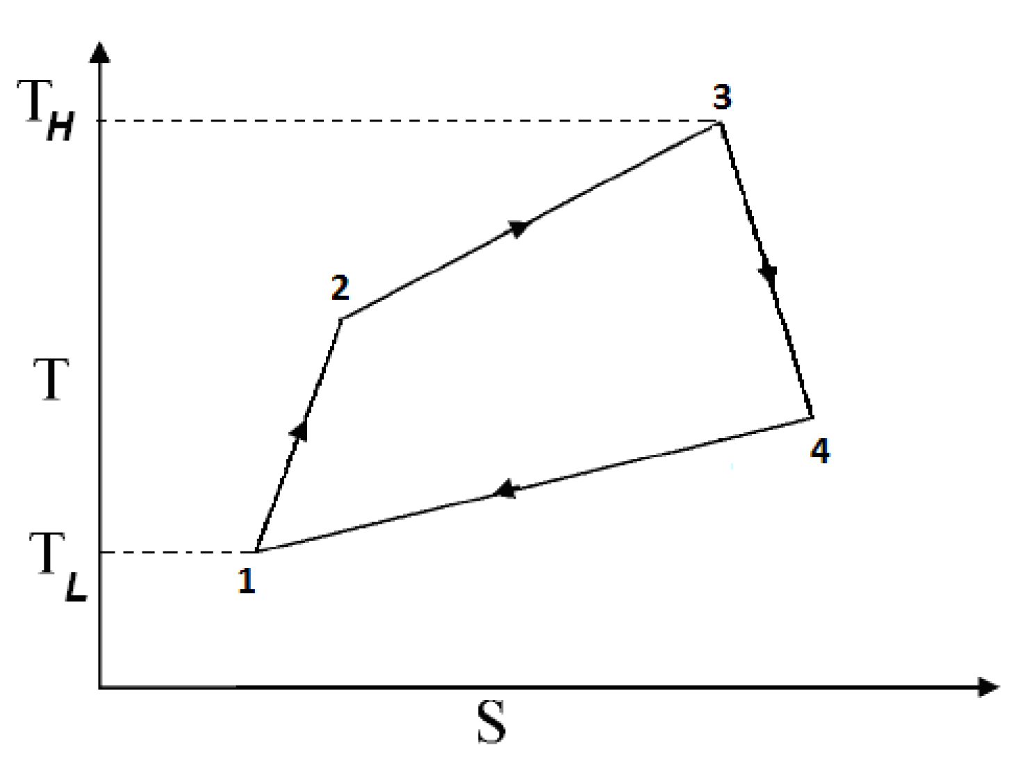
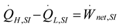
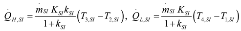
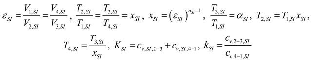
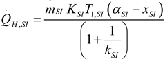
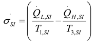
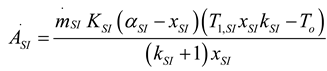
2.1.2.1. Irreversible SI Engine

From the first law of thermodynamics:
Entropy 15 03219 i012
where, W ˙ n e t , S I (power output), Q ˙ H , S I (added heat) and Q ˙ L , S I (rejected heat). Added and rejected heat can be defined as:
Entropy 15 03219 i013
for SI engine:
Entropy 15 03219 i014
where, ε (compression ratio), x (dimensionless compression ratio parameter), α (ratio of the highest temperature to lowest temperature), K (sum of the specific heats) and k (the ratio of specific heats). From the second law of thermodynamics:
Entropy 15 03219 i015
where, I S I (internal irreversibility parameter for SI engine). I S I and Q ˙ H , S I can be obtained from the Equations (12)–(15),
Entropy 15 03219 i016
Entropy 15 03219 i017
Entropy generation is:
Entropy 15 03219 i018
Using Equation (1) and (12)–(18) A ˙ S I (available work for the SI engine) is obtained as:
Entropy 15 03219 i019
Here, in order to detect optimum compression rate, a derivative of the SI engine according to the compression rate of its finite-time exergy function is equalized to zero ( A ˙ S I x S I = 0 ) and corresponding value is:
Entropy 15 03219 i020

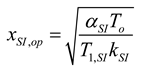
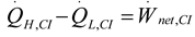
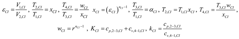
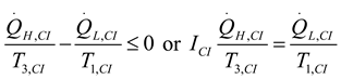
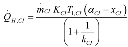
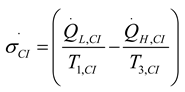
2.1.2.2. Irreversible CI Engine

From the first law of thermodynamics:
Entropy 15 03219 i021
where, W ˙ n e t , C I ( power output), Q ˙ H , C I (added heat) and Q ˙ L , C I (rejected heat). Added and rejected heat can be defined as:
Entropy 15 03219 i022
For CI engine:
Entropy 15 03219 i023
where, ε (compression ratio), x (dimensionless compression ratio parameter), r (cut-off ratio), w (dimensionless cut-off ratio parameter) α (ratio of the highest temperature to lowest temperature), K (sum of the specific heats) and k (ratio of specific heats). From the second law of thermodynamics:
Entropy 15 03219 i024
where, I C I (internal irreversibility parameter for CI engine). I C I and Q ˙ H , C I can be obtained from the Equations (21)–(24):
Entropy 15 03219 i025
Entropy 15 03219 i026
Entropy generation is:
Entropy 15 03219 i027
Using Equation (1) and (21)–(27) A ˙ C I (available work output) is obtained as:
Entropy 15 03219 i028
Here, in order to detect the optimum compression rate, a derivative of CI engine according to the compression rate of its finite-time exergy function is equalized to zero ( A ˙ C I x C I = 0 ) and corresponding value is:
Entropy 15 03219 i029

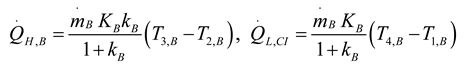
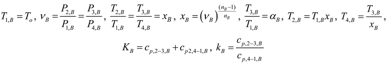
2.1.3. Thermodynamic Analysis of Irreversible Brayton Cycles

Since the Brayton cycle generates an ideal model for continuous combustion gas turbines, it has an importance in thermodynamic optimization studies. There are various studies examining parameters such as maximum power, maximum power density, and thermal efficiency of the Brayton cycle under finite time, finite area and finite rate restrictions and which determine its performance limits [29,30,31,32,33,34,35,36,37,38,39,40,41,42,43,44,45,46,47,48,49,50,51,52,53,54,55]. Temperatures and pressures in the process of Brayton cycle are the function of pressure ratio. That’s why, pressure ratio selected as optimization parameter. Figure 2 shows the T-s diagram of the irreversible Brayton cycle. From the first law of thermodynamics:
Entropy 15 03219 i030
Where, W ˙ n e t , B (power output), Q ˙ H , B (added heat) and Q ˙ L , B (rejected heat). Added and rejected heat can be defined as:
Entropy 15 03219 i031
for Brayton cycles:
Entropy 15 03219 i032
where, ν (pressure ratio), x (dimensionless pressure ratio parameter), α (ratio of the highest temperature to lowest temperature), K (sum of the specific heats) and k (ratio of specific heats). From the second law of thermodynamics:
Entropy 15 03219 i033
where, I B (internal irreversibility parameter for Brayton cycle). I B and Q ˙ L , B can be obtained from the Equations (30)–(33),
Entropy 15 03219 i034
Entropy 15 03219 i035
Entropy generation is:
Entropy 15 03219 i036
Investigating Equations for Baryton cycle available work output is equal to power output at this cycle. Using Equation (1) and (30)–(36) A ˙ B (available work output for the Brayton cycle) is obtained as:
Entropy 15 03219 i037
Here, in order to detect optimum pressure rate, a derivative of the Brayton cycle according to the compression rate of its finite-time exergy function is equalized to zero ( A ˙ B x B = 0 ) and corresponding value is:
Entropy 15 03219 i038

2.1.4. Thermodynamic Analysis of Irreversible Stirling and Ericsson Cycles

Ericsson and Stirling engines have attracted the attention of several generations of engineers and physicists due to their theoretical potential to provide high conversion efficiency that approached those of the Carnot cycle. However, use of these engines did not prove to be successful due to relatively poor material technologies available at that time. As the world community has become much more environmentally conscious, further attention in these engines has been again received because these engines are inherently clean and thermally more efficient. Moreover, as a result of advances in material technology, these engines are currently being considered for variety of applications due to their many advantages like low noise, less pollution and their flexibility as an external combustion engine to utilize a variety of energy sources or fuels. These engines are also under research and development for their use as heat pumps, replacing systems that are not ecological friendly and environmentally acceptable. Nowadays, the popularity of these engines is growing rapidly due to their many advantages like being more efficient, less pollution levels and their flexibility as external combustion engines to utilize different energy sources such as solar energy. The central receiver and parabolic dish solar systems based Stirling/Ericsson heat engine is more efficient and suitable for both the terrestrial [56,57] and non-terrestrial [58,59] solar installations. In the literature, Erbay and Yavuz, investigated irreversible Stirling and Ericsson engines [60,61,62,63]. In this study their model was adopted for the analyzing of the Stirling-Ericsson engines. Temperatures and pressures in the process of the Stirling and Ericsson engines are the function of compression and pressure ratios. That’s why, compression and pressure ratios selected as optimization parameters. In Figure 3, it can be seen that analyzed Stirling-Ericsson engines T-s Diagram.
Figure 3. T-s (temperature-entropy) diagram of irreversible Stirling-Ericsson cycle (TH = high temperature, TL = low temperature) [60,61,62,63].
Entropy 15 03219 g003
From the first law of thermodynamics:
Entropy 15 03219 i039
where, W ˙ n e t , S E (power output), Q ˙ H , S E (added heat) and Q ˙ L , S E (rejected heat). Added and rejected heat can be defined as:
Entropy 15 03219 i040
Entropy 15 03219 i041
where, ε (compression ratio), ν (pressure ratio), x (dimensionless compression ratio parameter for Stirling engine and dimensionless pressure ratio for Ericsson engine), α (ratio of the highest temperature to lowest temperature), θ (dimensionless coefficient for Ericsson and Stirling engines), n (polytrophic coefficient), λ (isentropic coefficient), T H (high temperature) and T L (low temperature). From the second law of thermodynamics:
Entropy 15 03219 i042
where, I S E r (internal irreversibility parameter for Stirling and Ericsson engines). I S E can be obtained from the Equations (39)–(42):
Entropy 15 03219 i043
Entropy generation is:
Entropy 15 03219 i044
Using Equations (1) and (39)–(44) A ˙ S E (available work output for the Stirling and Ericsson engines) is obtained as:
Entropy 15 03219 i045
Here, in order to detect an optimum pressure rate for the Ericsson cycle or an optimum compression rate for the Stirling cycle, a derivative of cycle of Stirling-Ericsson cycles according to the compression of their finite-time exergy function is equalized to zero ( A ˙ S E x S E = 0 ) and corresponding value is:
Entropy 15 03219 i046

2.2. Heat Pump and Refrigeration Cycles

Heat pump and refrigeration cycles operate with the same cycle requiring power. Cycles which are more efficient and less harmful to the environment must be designed by reducing the power obtained from outside resource and reducing entropy generation. In this section, limits of these cycles were determined by using finite-time exergy. Figure 4 shows the T-s diagram of irreversible heat pump and refrigerator cycles.
Figure 4. T-s (temperature-entropy) diagram of irreversible heat pump and refrigerators cycles (TH = high temperature, TL = low temperature).
Entropy 15 03219 g004

2.2.1. Thermodynamic Analysis of General Irreversible Heat Pump and Irreversible Refrigerator Systems

From the first law of thermodynamics:
Entropy 15 03219 i047
where, W ˙ n e t , h r (power input), Q ˙ H , h r (added heat) and Q ˙ L , h r (rejected heat). Rejected and added heat can be defined as:
Entropy 15 03219 i048
where, ϕ (heat conductance). From the second law of thermodynamics:
Entropy 15 03219 i049
where, I h r (internal irreversibility parameter for heat pump or refrigerator cycle). Entropy generation is:
Entropy 15 03219 i050
Using Equation (1) and Equations (47)–(50) A ˙ h r (available work input for the heat pump and refrigeration cycles) is obtained as:
Entropy 15 03219 i051
As seen at Figure 19 and Figure 23, heat pump and refrigeration cycles haven’t an optimum point minimizing available power input, but there is a critical point maximizing power output input. The derivative of the heat pump—refrigerator cycle according to evaporator and temperature is equalized to zero ( A ˙ h r T E , h r = 0 ) and it can be provided critical temperature as:
Entropy 15 03219 i052
Unlike evaporator temperature, as seen Figure 19 and Figure 23, condenser temperature has linear effects on the available power input and has not an optimum point. However, Equation of linear change of the available work input with condenser temperature can be defined with regression:
Entropy 15 03219 i053
where, R2 is the coefficient of determination for the regression.

3. Results and Numerical Examples

In this section, optimum points for all basic thermodynamic cycles were determined and they were discussed in detail for each cycle separately. Numerical examples were selected in a way that would be close to the values met in practice and by using references [29,30,31,32,33,34,35,36,37,38,39,40,41,42,43,44,45,46,47,48,49,50,51,52,53,54,55] for irreversible Brayton cycle, [56,57,58,59,60,61,62,63] for irreversible Stirling and Ericsson cycles, [64,65,66,67,68,69,70,71,72,73,74,75,76,77,78,79,80,81,82,83,84,85,86,87,88] foe irreversible SI and CI cycles, [89,90,91,92,93,94,95,96,97,98,99,100,101,102,103] for irreversible refrigeration and heat pump cycles and [104] for irreversible Rankine cycle.

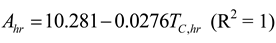
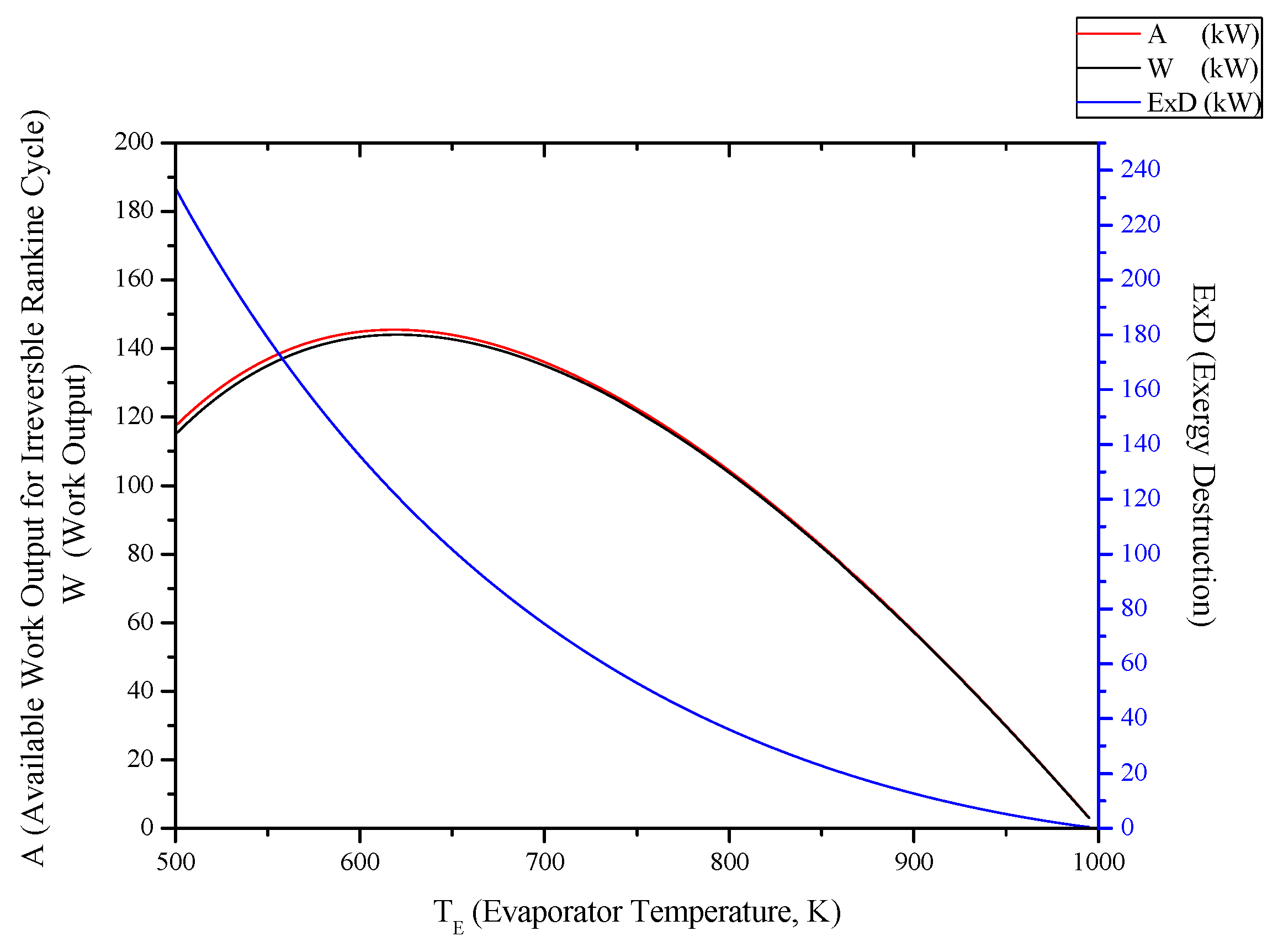
3.1. Irreversible Rankine Cycle

TH,R = 1000 K, TL,R = 300 K, ϕ E , R = 1 kW/K and, ϕ C , R = 1 kW/K are set. Figure 5 shows the variation of power output ( W ˙ ),available work output ( A ˙ ), and exergy destruction (ExD), of the Rankine cycle with regard to evaporator temperature. Evaporator temperature for the Rankine cycle was detected as 618.568 K. It is seen that with the increase of evaporator temperature, available work output and power output rise up to the optimum evaporator temperature and then they decrease logarithmically. In addition to that, exergy destruction decrease while evaporator temperature increase. In Figure 6, it can be seen that thermal efficiency (η) and second law efficiency ( φ ) increase with evaporator temperature. It can be seen in Figure 7 that available work output and power output decrease with condenser temperature linearly, while exergy destruction increases. In Equation (11), the linear function of available work output with regard to the condenser temperature was shown. In Figure 8, thermal efficiency, second law efficiency decrease with condenser temperature linearly.
Figure 5. Effect of TE (evaporator temperature) on the A (available work output for irreversible Rankine cycle), W (power output) and ExD (exergy destruction) for irreversible Rankine cycle (TC,R =350 K, IR = 1.1).
Entropy 15 03219 g005
Figure 6. Effect of TE (evaporator temperature) on the η (first law efficiency), φ (second law efficiency) for irreversible Rankine cycle (TC,R = 350 K, IR = 1.1).
Entropy 15 03219 g006
Figure 7. Effect of TC (condenser temperature) on the A (available work output for irreversible Rankine cycle), W (power output) and ExD (exergy destruction) for irreversible Rankine cycle (TE,R = 600 K, IR = 1.1).
Entropy 15 03219 g007
Figure 8. Effect of TC (condenser temperature) on the η (first law efficiency), φ (second law efficiency) for irreversible Rankine cycle (TE,R = 600 K, IR = 1.1).
Entropy 15 03219 g008

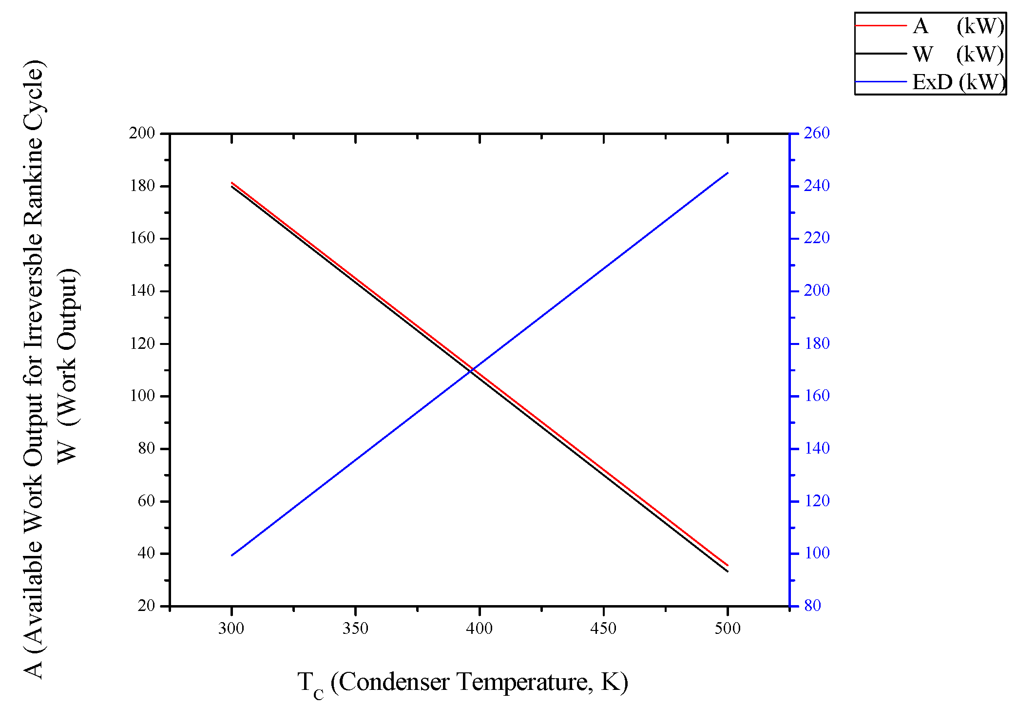
3.2. Irreversible SI Engine

For numerical calculations, the powering parameters of the SI engine are as follows: T1,SI = 350 K, αSI = 4, m ˙ S I = 0.5 kg/s, kCI = 1.02, KCI = 2.5 kJ/kgK, nSI = 1.37. Figure 9 and Figure 10 show the variation of power output ( W ˙ ), thermal efficiency (η), second law ( φ ), available work output ( A ˙ ), exergy destruction and the internal irreversibility parameter (I) of the SI engine with regard to compression rate. The optimum compression rate for the SI engine was detected as 10.555. It is seen that with the increase of the compression rate, available work output and power output rise up to the optimum compression rate, then start to decrease. Thermal efficiency and second law efficiency increase, while, exergy destruction and the internal irreversibility parameter decrease. The decrease of exergy destruction is directly proportional since entropy production is the result of irreversibility.
Figure 9. Effect of ε (compression ratio) on the A (available work output for irreversible SI engine), W (power output) and ExD (exergy destruction) for irreversible SI engine.
Entropy 15 03219 g009
Figure 10. Effect of ε (compression ratio) on the η (first law efficiency), φ (second law efficiency) and I (internal irreversibility parameter) for irreversible SI engine.
Entropy 15 03219 g010

3.3. Irreversible CI Engines

For numerical calculations, the powering parameters of the CI engine are as follows: T1,CI = 350 K, αSI = 6, m ˙ C I = 0.5 kg/s, kCI = 1.1, KCI = 3 kJ/kgK, wCI = 1.23, nCI = 1.37. Figure 11 and Figure 12 show the variation of power output ( W ˙ ), thermal efficiency (η), second law efficiency ( φ ), available work output ( A ˙ ), exergy destruction and the internal irreversibility parameter (I) of the CI engine with regard to compression rate. The optimum compression rate for the CI engine was detected as 21.386. It is seen that with the increase of the compression rate, available work output and power output rise up to the optimum compression rate, then start to decrease. Thermal efficiency and second law efficiency increase, while, exergy destruction and the internal irreversibility parameter decrease. The decrease of exergy destruction is directly proportional since entropy production is the result of irreversibility.
Figure 11. Effect of ε (compression ratio) on the A (available work output for irreversible CI engine), W (power output) and ExD (exergy destruction) for irreversible CI engine.
Entropy 15 03219 g011
Figure 12. Effect of ε (compression ratio) on the η (first law efficiency), φ (second law efficiency) and I (internal irreversibility parameter) for irreversible CI engine.
Entropy 15 03219 g012

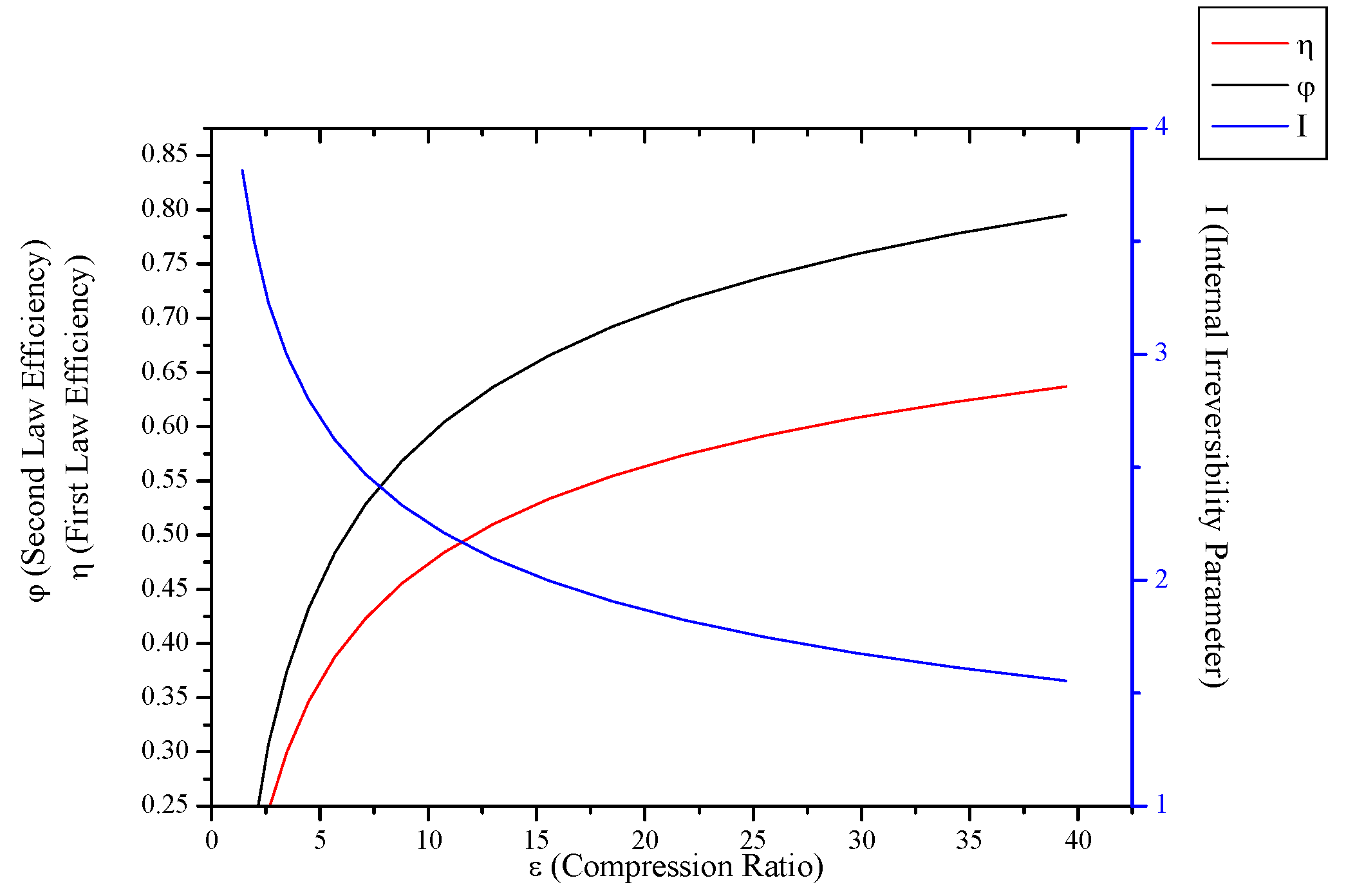
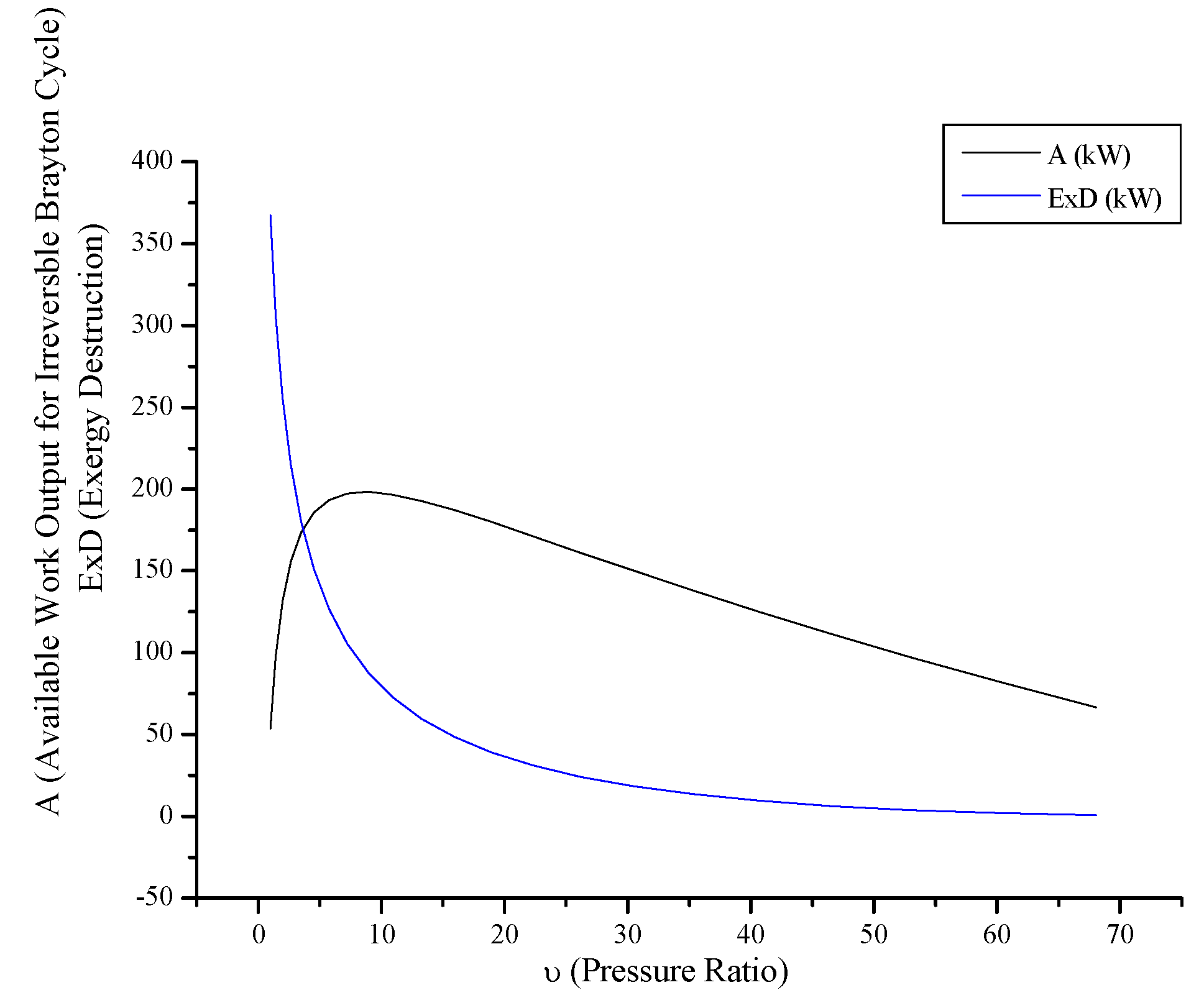
3.4. Irreversible Brayton Cycles

For numerical calculations, the powering parameters of the Brayton cycle are as follows: T1,B = 300 K, αB = 3.5, m ˙ B = 0.5 kg/s, kCI = 1.1, KCI = 3 kJ/kgK, nB = 1.37. Figure 13 and Figure 14 show the variation of power output ( W ˙ ), thermal efficiency (η), second law efficiency ( φ ), available work output ( A ˙ ), exergy destruction and the internal irreversibility parameter (I) of the Brayton cycle with regard to pressure rate. The optimum compression rate for the Brayton cycle was detected as 8.659. It is seen that with the increase of the compression rate, available work output and power output rise up to the optimum compression rate, then to decrease. Thermal efficiency and second law efficiency increases, while, exergy destruction and the internal irreversibility parameter decrease. The decrease of exergy destruction is directly proportional since entropy production is the result of irreversibility.
Figure 13. Effect of ν (pressure ratio) on the A (available work output for irreversible Brayton cyle), W (power output) and ExD (exergy destruction) for irreversible Brayton engine.
Entropy 15 03219 g013
Figure 14. Effect of ν (pressure ratio) on the η (first law efficiency), φ (second law efficiency) and I (internal irreversibility parameter) for irreversible Brayton cycle.
Entropy 15 03219 g014

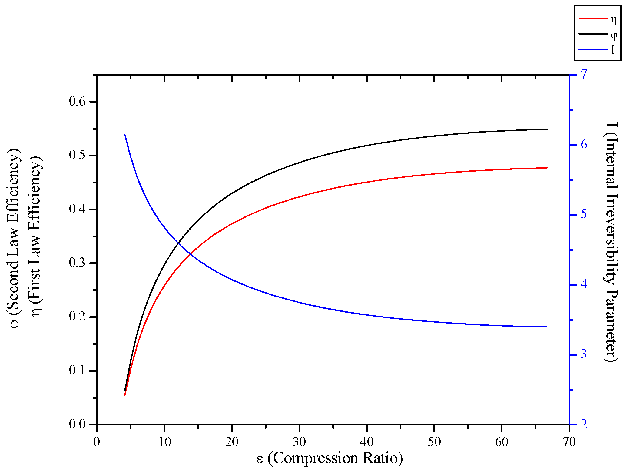
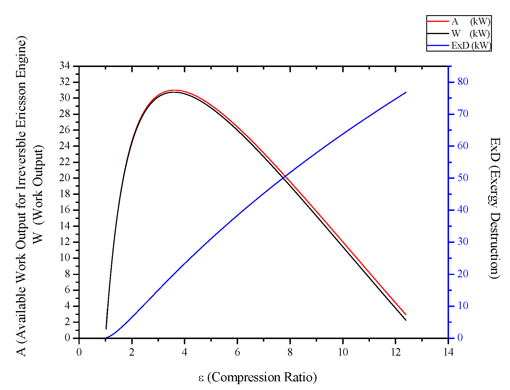
3.5. Irreversible Stirling and Ericsson Engines

For numerical calculations, the powering parameters of the Stirling—Ericsson cycle are as follows: T1,SE = 350 K, αSE = 3, m ˙ S = 0.5 kg/s, θ = 5.34, R= 0.287 kJ/kgK, TH,SE = 1000 K, TL,SE = 300 K. Figure 15, Figure 16, Figure 17 and Figure 18 show the variation of power output ( W ˙ ), thermal efficiency (η), second law efficiency ( φ ), available work output ( A ˙ ), exergy destruction and the internal irreversibility parameter (I) of Stirling-Ericsson cycle with regard to compression rate. The optimum compression and pressure rates of the Stirling-Ericsson cycle were detected as 3.629. It is seen that with the increase of pressure and compression rates, available work output and power output to the optimum compression rate and then start to decrease. In addition to that, exergy destruction decrease while evaporator compression or pressure ratio. It can be seen that thermal efficiency (η) and second law efficiency ( φ ) decrease with compression or pressure ratio. On the contrary, internal irreversibility parameter rises up with compression or pressure ratio. Reason of decreasing at thermal efficiency, second law efficiency and increasing at the exergy destruction is to rise of internal irreversibility. Because, increasing at the internal irreversibility causes the entropy generation.
Figure 15. Effect of ε (compression ratio) on the A (available work output for irreversible Stirling engine), W (power output) and ExD (exergy destruction) for irreversible Stirling engine.
Entropy 15 03219 g015
Figure 16. Effect of ε (compression ratio) on the η (first law efficiency), φ (second law efficiency) and I (internal irreversibility parameter) for irreversible Stirling engine.
Entropy 15 03219 g016
Figure 17. Effect of ν (pressure ratio) on the A (available work output for irreversible Ericsson engine), W (power output) and ExD (exergy destruction) for irreversible Ericsson engine.
Entropy 15 03219 g017
Figure 18. Effect of ν (pressure ratio) on the η (first law efficiency), φ (second law efficiency) and I (internal irreversibility parameter) irreversible Ericsson engine.
Entropy 15 03219 g018

3.6. Irreversible Heat Pump and Refrigeration Cycles

For numerical calculations, the powering parameters of the heat pump and refrigeration cycle are as follows: TH,hr = 300 K, TL,hr = 290 K, ϕ E , h r = 1 kW/K and, ϕ C , h r = 1 kW/K. Figure 19 show the variation of power input ( W ˙ ), Available power input ( A ˙ ) and exergy destruction of heat pump cycle with regard to condenser temperature. It can be seen in Figure 19 that available power input decreases with condenser temperature linearly. Same graphic shows exergy destruction, power input heating load of the heat pump cycle increased. In Figure 20, coefficient of performance increase linearly, while second law efficiency decrease with condenser temperature logarithmically. In Figure 21 show the variation of power input ( W ˙ ), Available power input ( A ˙ ) and exergy destruction of heat pump with regard to evaporator temperature. With the increase in evaporator temperature exergy destruction, power input, heat load in the heat pump cycle decreasing logarithmically. Available work input increases until critical temperature condenser temperature and starts to decrease after that value. It can be seen that available work input has negative values for the heat pump cycle until 279 K. Because, exergy destruction is bigger than exergy input until this value. Assuming condenser temperature as 370 K, the optimum condenser temperature for the heat pump was detected as 284.234 K. In Figure 22, it can be seen that coefficient of performance (COP) increases, while second law efficiency ( φ ) decreases with evaporator temperature for heat pump. Figure 23 shows that available power input decreases with condenser temperature linearly for refrigeration cycle and exergy destruction, power input of the refrigeration cycle increased, while cooling load is constant. In Figure 24, it can be seen that coefficient of performance increase linearly, while second law efficiency decrease with condenser temperature logarithmically for refrigeration cycle. In Figure 25, with the increase in evaporator temperature exergy destruction, power input, cooling load in the refrigeration cycle decreasing logarithmically. Available work input increases until optimum temperature condenser temperature and starts to decrease after that value. It can be seen that available work input has negative values for the both cycle until 279 K. Because, exergy destruction is bigger than exergy input until this value. Assuming condenser temperature as 370 K, the optimum condenser temperature for the refrigerator was detected as 284.234 K. Finally in Figure 26, it can be seen that coefficient of performance (COP) increases, while second law efficiency ( φ ) decreases with evaporator temperature for refrigerator.
Figure 19. Effect of TC (condenser temperature) on the QH (heating load), W (power input), A (available power input for irreversible heat pump) and ExD (exergy destruction) for irreversible heat pump (TE,hr = 280 K, Ihr = 1.1).
Entropy 15 03219 g019
Figure 20. Effect of TC (condenser temperature) on the COP (coefficient of performance), φ (second law efficiency) for irreversible heat pump (TE,hr = 280 K, Ihr = 1.1).
Entropy 15 03219 g020
Figure 21. Effect of TE (evaporator temperature) on the QH (heating load), W (power input), A (available power input for irreversible heat pump) and ExD (exergy destruction) for irreversible heat pump (TC,hr = 370 K, Ihr = 1.1).
Entropy 15 03219 g021
Figure 22. Effect of TE (evaporator temperature) on the COP (coefficient of performance), φ (second law efficiency) for irreversible heat pump (TC,hr = 370 K, Ihr = 1.1).
Entropy 15 03219 g022
Figure 23. Effect of TC (condenser temperature) on the QL (cooling load), W (power input), A (available power input for irreversible refrigerator) and ExD (exergy destruction) for irreversible refrigerator (TE,hr = 280 K, Ihr = 1.1).
Entropy 15 03219 g023
Figure 24. Effect of TC (condenser temperature) on the COP (coefficient of performance), φ (second law efficiency) for irreversible refrigerator (TE,hr = 280 K, Ihr = 1.1).
Entropy 15 03219 g024
Figure 25. Effect of TE (evaporator temperature) on the QL (cooling load), W (power input), A (available power input for irreversible refrigerator) and ExD (exergy destruction) for irreversible refrigerator for irreversible refrigerator (TC,hr = 370 K, Ihr = 1.1).
Entropy 15 03219 g025
Figure 26. Effect of TE (evaporator temperature) on the COP (coefficient of performance), φ (second law efficiency) for irreversible refrigerator (TC,hr = 370 K, Ihr = 1.1)
Entropy 15 03219 g026

4. Conclusions

In this study, available work output or input optimization was made for all basic thermodynamic irreversible cycles and the results were discussed. All cycles were evaluated by taking exergy destruction, first and second law efficiencies, COP, power output or power input and internal irreversibility parameters into account.
Power generation cycles:
  • For Rankine, Stirling and Ericsson cycles, which are external combustion engines, available work output and power output has the very close values. On the contrary, difference of these values is much higher at SI, CI and Brayton cycles.
  • While available work output is maximum, power output is maximum too for the all power generation cycles.
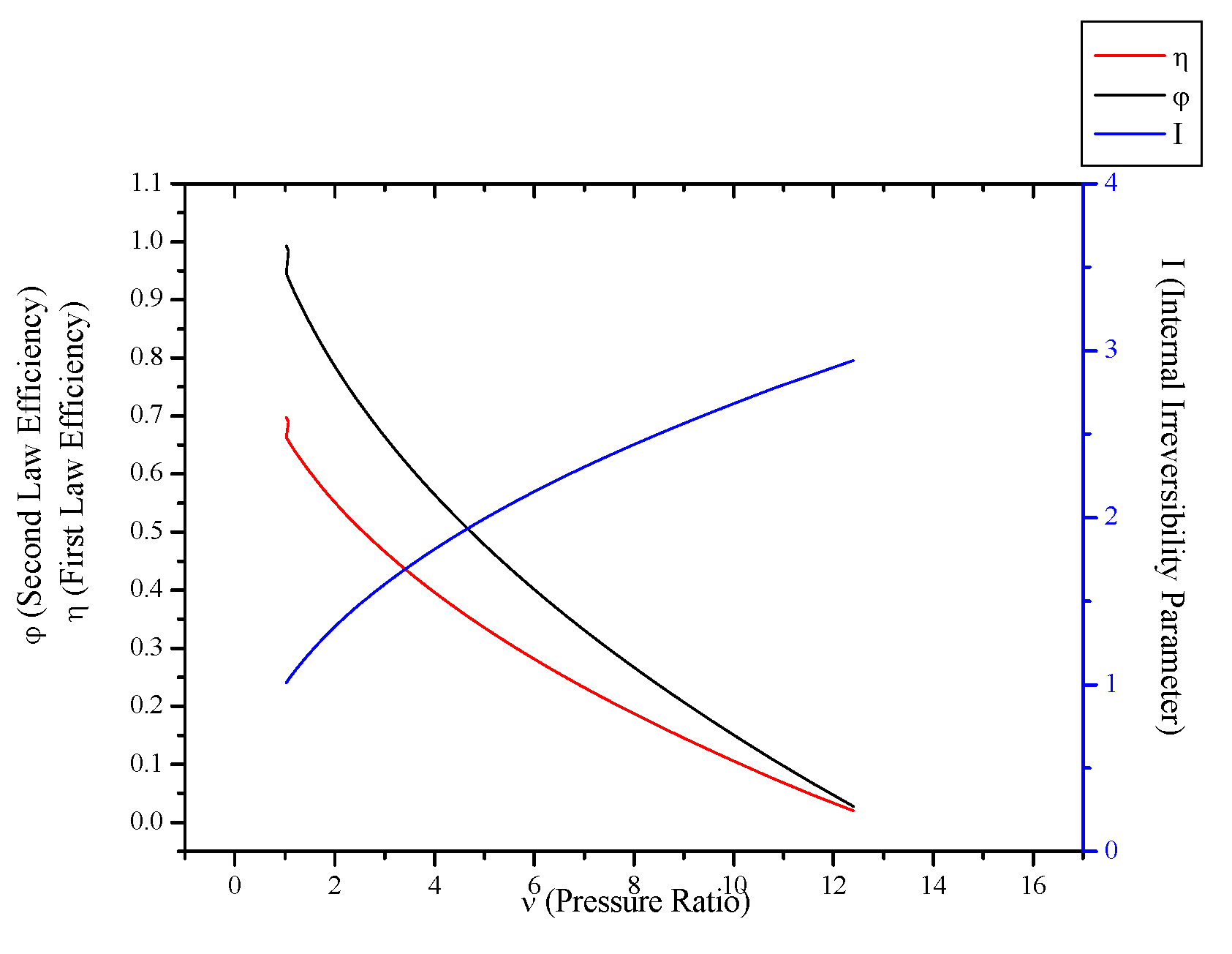
  • When optimization parameters are increased, first and second law efficiencies decrease and exergy destruction internal irreversibility parameter increase for Rankine, Stirling and Ericsson cycles.
  • When optimization parameters are increased, first and second law efficiencies increase and exergy destruction internal irreversibility parameter decrease for SI, CI and Brayton cycles.
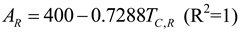
  • It can be seen that TC parameter should be minimum for Rankine cycle to improve its performance.
Heat pump and refrigeration cycles:
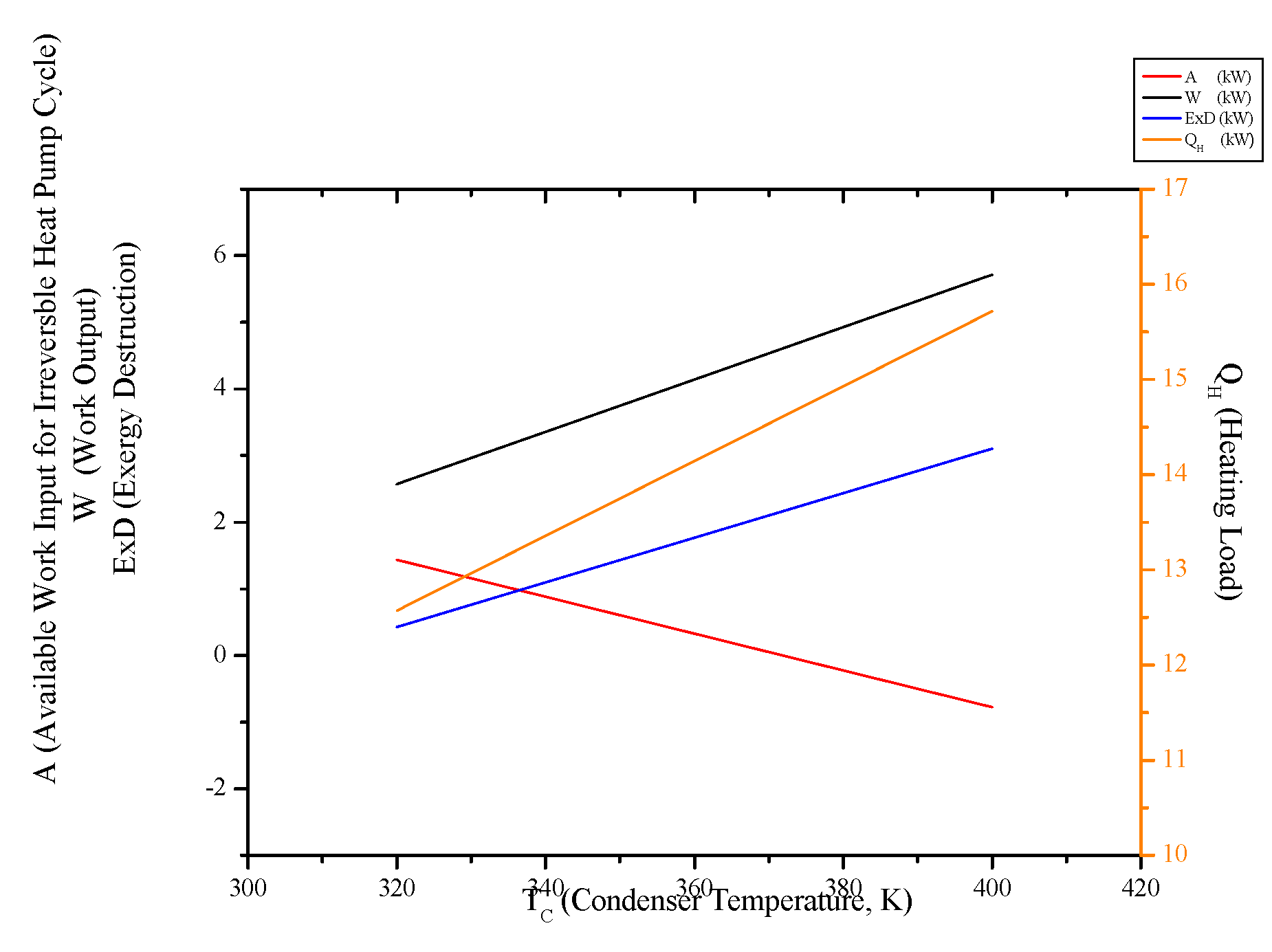
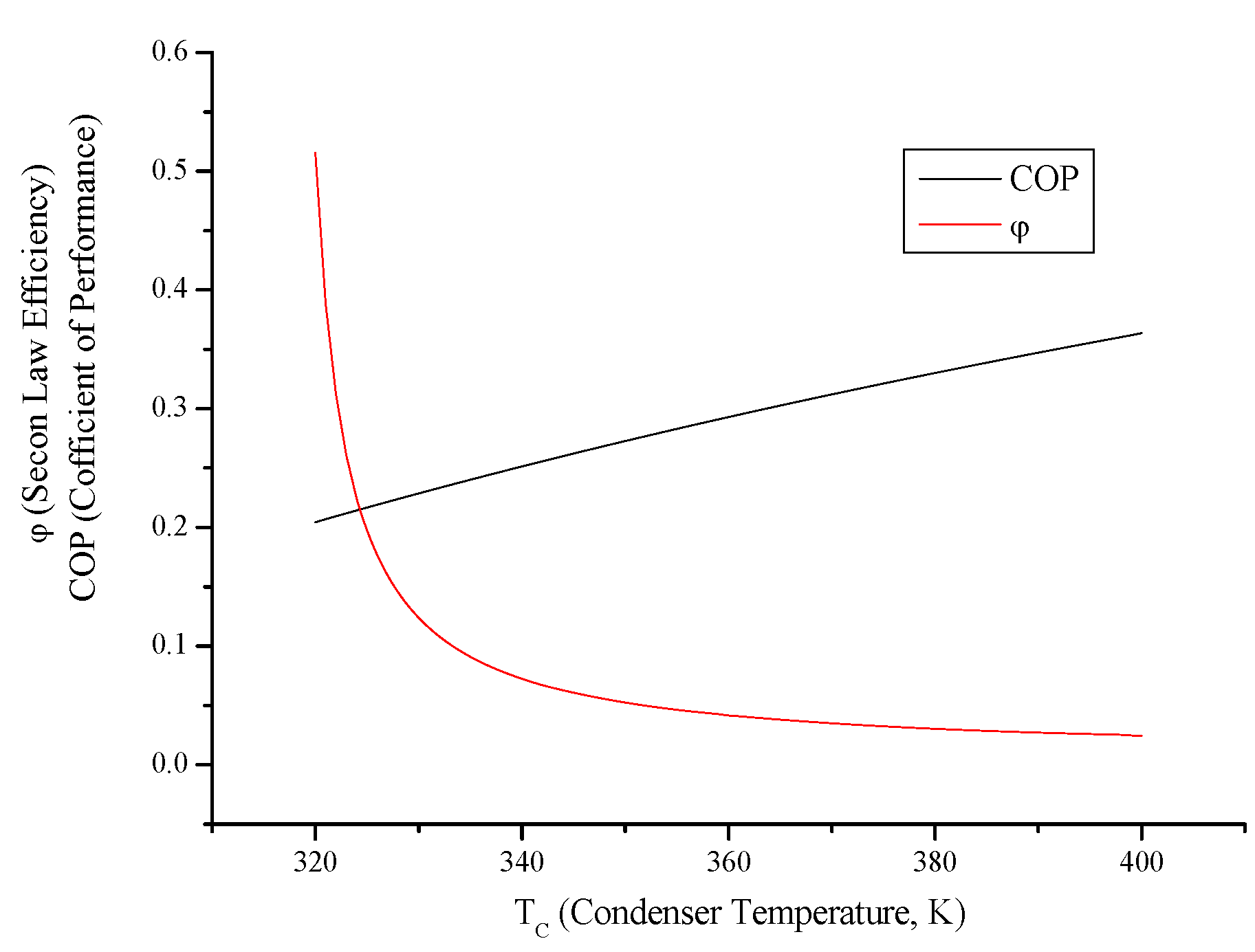
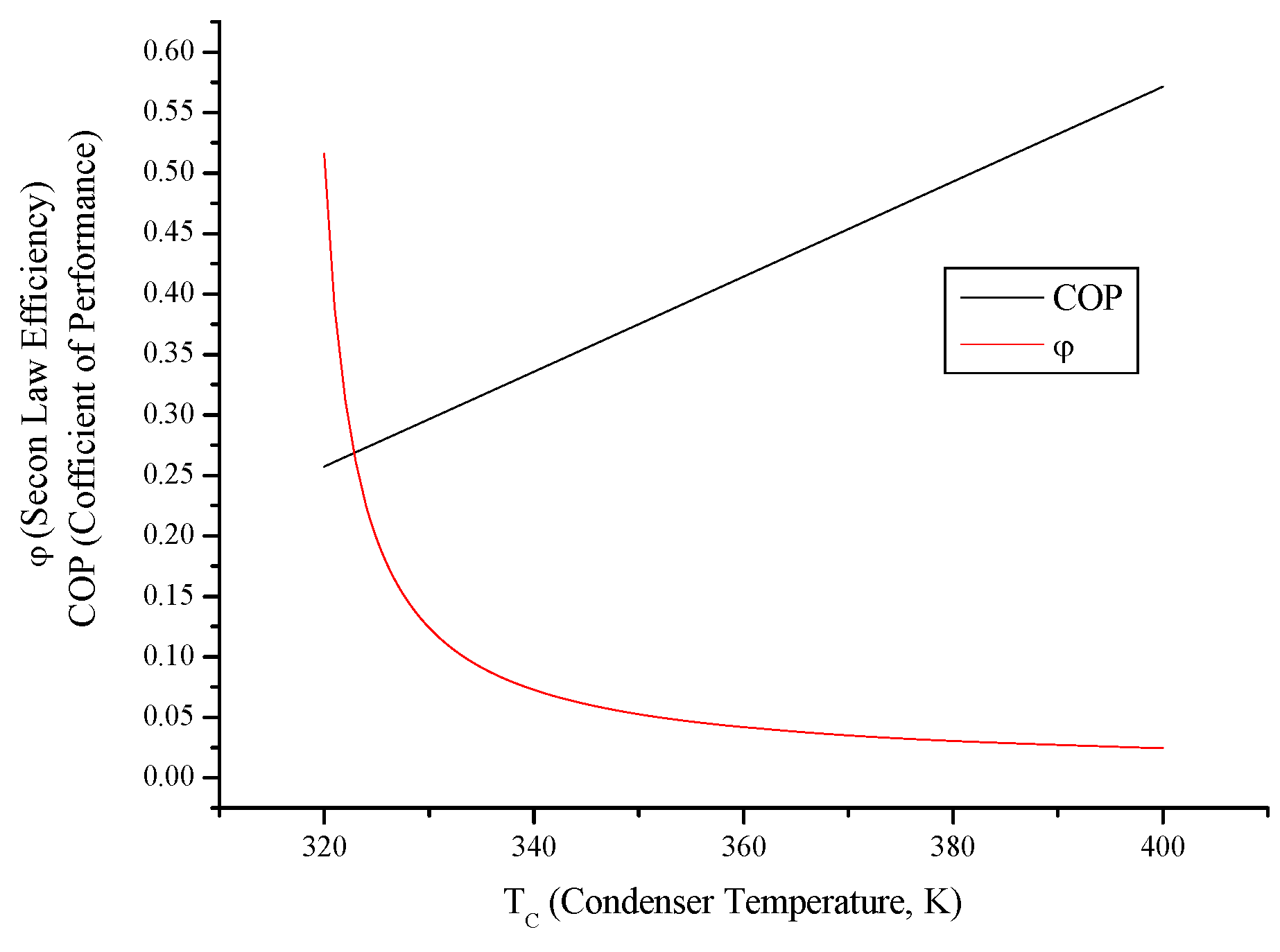
  • Both cycles’ work input, COP and exergy destruction increase with condenser temperature while available work output and second law efficiency decrease. In addition to those, heating load increase wit condenser temperature for the heat pump and cooling load decreases for the refrigerator.
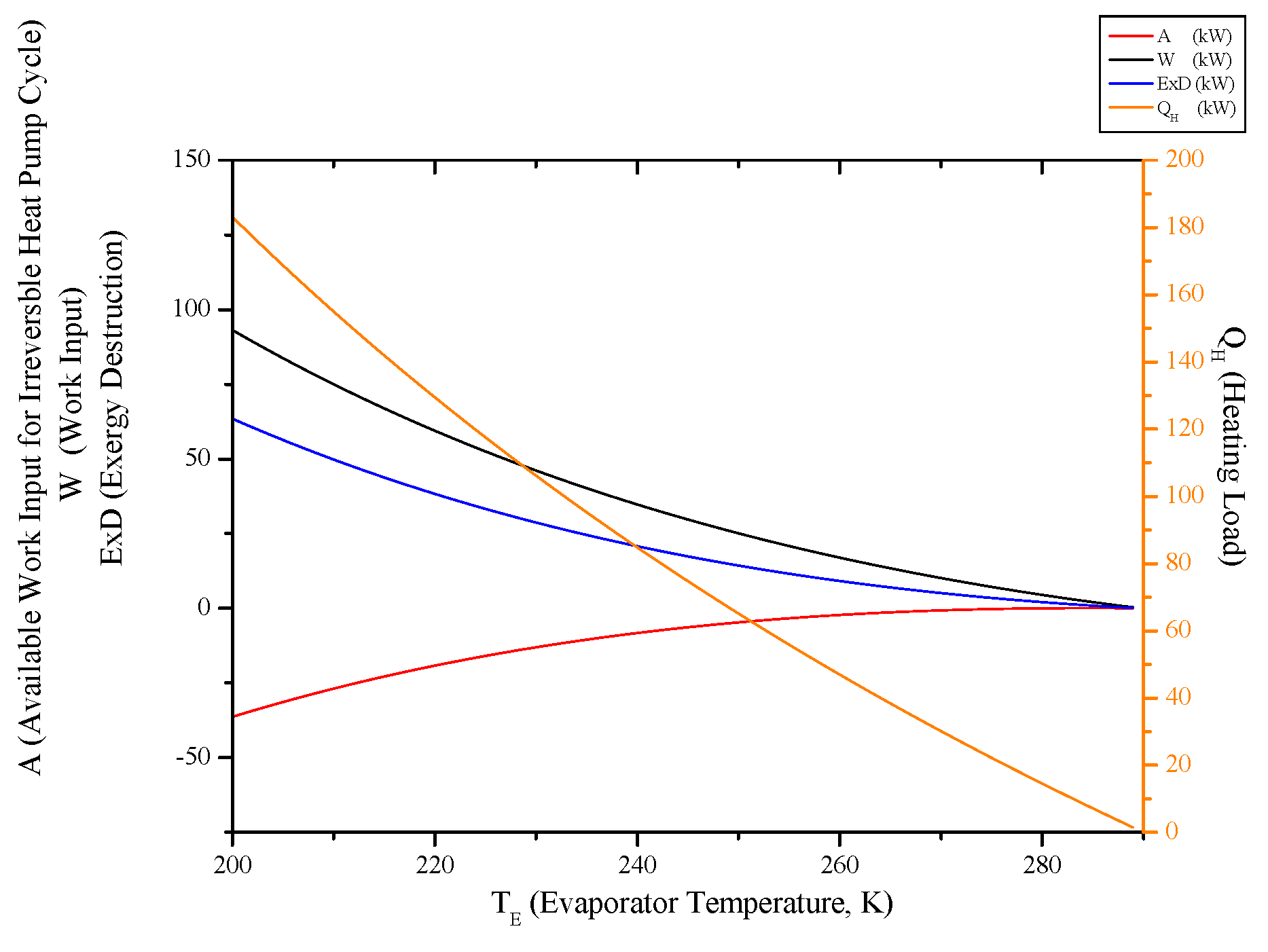
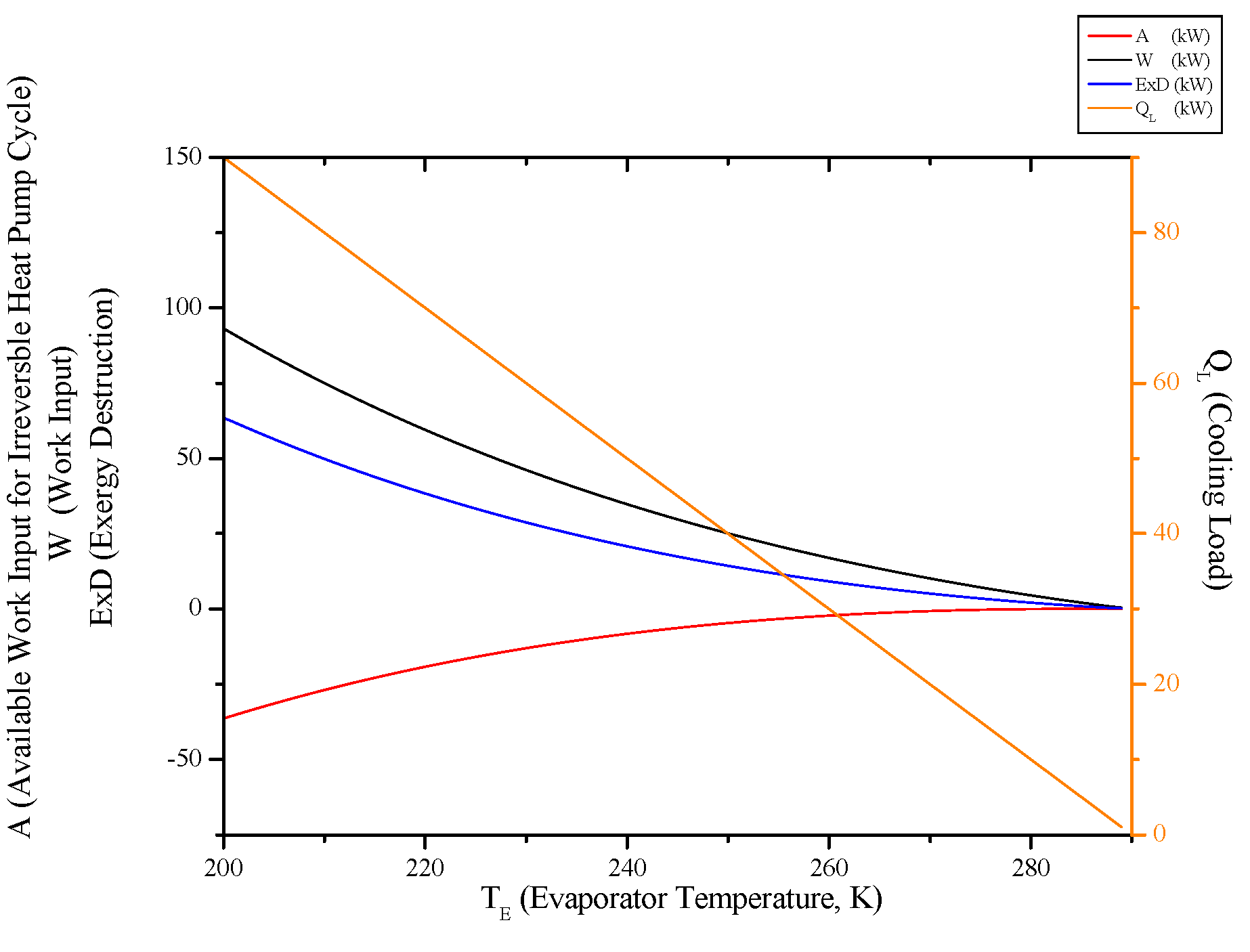
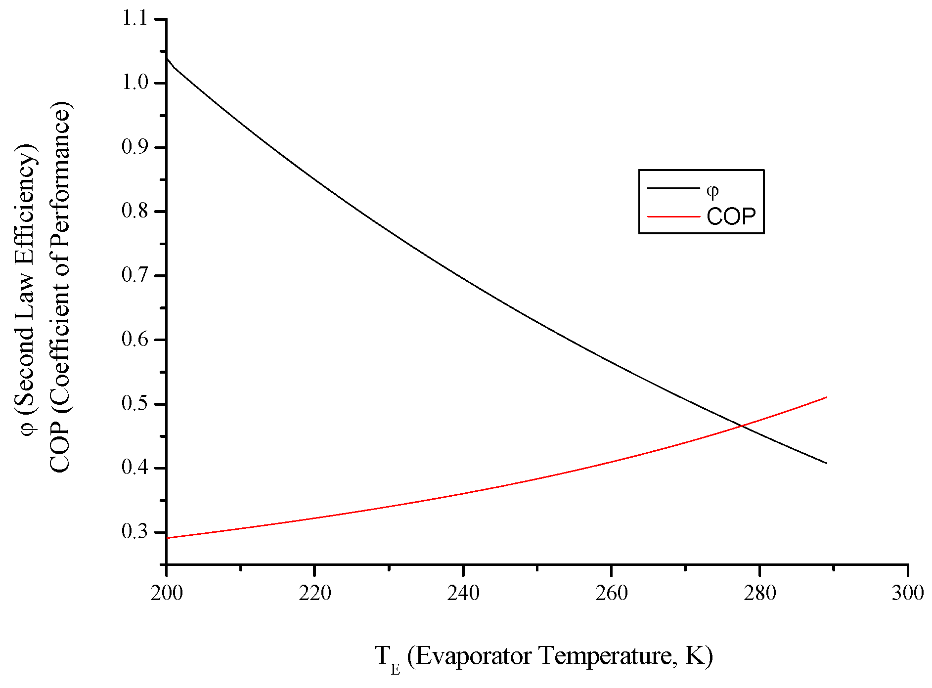
  • Evaluating evaporator temperature for both cycle, cooling load for the refrigeration cycle heating load for the heat pump cycle, exergy destructions and second law efficiencies diminish with evaporator temperature, while available work outputs and COP rise up. This point of view, it can be said that evaporator temperature should be at low temperature. available power input.
In addition those, it was determined thermodynamically limits of all cycles in this paper. Because, figures drew for operation ranges of cycles, that’s why, it is impossible thermodynamically that cycles can’t be operated out of this limits. By regarding the results presented within the scope of this study, the actual thermodynamic cycles to be used were aimed to be designed with the least exergy destruction and as environmental friendly as possible.

Conflict of Interest

The authors declare no conflict of interest.

Nomenclature

A ˙
available work for the actual cycles (kW)
c
specific heat (kJ/kgK)
C O P
coefficient of performance
E x D
exergy destruction (kW)
I
internal irreversibility parameter
k
ratio of specific heats
K
sum of specific heats (kJ/kgK)
m
mass flow (kg/s)
n
polytrophic coefficient
r
cut-off ratio
R
ideal gas constant (kJ/kgK)
Q ˙
heat (kW)
T
temperature(K)
W ˙
power (kW)
x
dimensionless compression ratio or dimensionless pressure ratio parameter
Subscripts
B
Brayton
C
condenser
C I
compression injection engine
c r
critical point
e
Ericsson engine
S
Stirling
h
heat pump
H
high
h r
heat pump or refrigeration
L
low
r
refrigerator
R
Rankine
S
Stirling
S E r
Stirling or Ericsson engine
S I
spark injection engine
o p
optimum point
Greek letters
α
ratio of the highest and the lowest temperature of the cycle
ε
compression ratio
ϕ
heat conductance (kW/K)
λ
isentropic coefficient
η
efficiency
ν
pressure ratio
θ
a coefficient for Ericsson and Stirling engines
σ
entropy generation (kW/K)

References

  1. Chen, L.; Wu, C.; Sun, F. Finite time thermodynamic optimization or entropy generation minimization of energy systems. J. Non-Equilib. Thermodyn. 1999, 24, 327–359. [Google Scholar] [CrossRef]
  2. Wu, C. Recent Advances in Finite Time Thermodynamics; Wu, C., Chen, L., Chen, J., Eds.; Nova Science Publishers: New York, NY, USA, 1999. [Google Scholar]
  3. Chen, L.; Sun, F. (Eds.) Advances in Finite Time Thermodynamics: Analysis and Optimization; Nova Science Publishers: New York, NY, USA, 2004.
  4. Andresen, B.; Rubin, M.H.; Berry, R.S. Availability for finite-time processes. General theory and a model. J. Chem. Phys. 1983, 87, 2704–2713. [Google Scholar] [CrossRef]
  5. Mironova, V.A.; Tsirlin, A.M.; Kazakov, V.A.; Berry, R.S. Finite–time thermodynamics: Exergy and optimization of time-constrained processes. J. Appl. Phys. 1994, 76, 629–636. [Google Scholar] [CrossRef]
  6. Sieniutycz, S.; Spakovsky, M.R.V. Finite time generalization of thermal exergy. Energy Convers. Manag. 1997, 39, 1432–1447. [Google Scholar] [CrossRef]
  7. Sieniutycz, S. Generalized Carnot problem of maximum power in finite time via Hamilton-Jacobi-Bellman theory. Energy Convers. Manag. 1998, 39, 1735–1743. [Google Scholar] [CrossRef]
  8. Sieniutycz, S. Carnot problem of maximum power from a finite resource interacting with environment in a finite time. Physica A 1999, 264, 234–263. [Google Scholar] [CrossRef]
  9. Sieniutycz, S. Hamilton-Jacobi-Bellman theory of dissipative thermal availability. Phys. Rev. E 1997, 56, 5051–5064. [Google Scholar] [CrossRef]
  10. Xia, S.; Chen, L.; Sun, F. Finite-time exergy with a finite heat reservoir and generalized radiative heat transfer law. Revista Mexicana De Fisica 2010, 56, 287–296. [Google Scholar]
  11. Song, H.; Chen, L.; Sun, F. Optimal expansion of heated powering fluid for maximum power output with generalized radiative heat transfer law. J. Appl. Phys. 2007, 102, 094901. [Google Scholar] [CrossRef]
  12. Denton, J.C. Thermal cycles in classical thermodynamics and nonequilibrium thermodynamics in contrast with finite time thermodynamics. Energy Convers. Manag. 2002, 43, 1583–1617. [Google Scholar] [CrossRef]
  13. Li, J.; Chen, L.; Sun, F. Optimal configuration of a class of endoreversible heat-engines for maximum power-output with linear phenomenological heat-transfer law. Appl. Energy 2007, 84, 944–957. [Google Scholar] [CrossRef]
  14. Li, J.; Chen, L.; Sun, F. Optimum work in real systems with a class of finite thermal capacity reservoirs. Math. Comput. Model. 2009, 49, 542–547. [Google Scholar] [CrossRef]
  15. Li, J.; Chen, L.; Sun, F. Maximum work output of multistage continuous Carnot heat engine system with finite reservoirs of thermal capacity and radiation between heat source and working fluid. Therm. Sci. 2010, 14, 1–9. [Google Scholar] [CrossRef]
  16. Li, J.; Chen, L.; Sun, F. Extremal work of an endoreversible system with two finite thermal capacity reservoirs. J. Energy Inst. 2009, 82, 53–56. [Google Scholar] [CrossRef]
  17. Xia, S.; Chen, L.; Sun, F. Optimal paths for minimizing entransy dissipation during heat transfer processes with generalized radiative heat transfer law. Appl. Math. Model. 2010, 34, 2242–2255. [Google Scholar] [CrossRef]
  18. Chen, L.; Song, H.; Sun, F. Endoreversible radiative heat engines for maximum efficiency. Appl. Math. Model. 2010, 34, 1710–1720. [Google Scholar] [CrossRef]
  19. Wu, F.; Chen, L.; Sun, F. Exergetic efficiency optimization for an irreversible quantum Brayton refrigerator with spin systems. Appl. Math. Model. 2010, 34, 617–625. [Google Scholar] [CrossRef]
  20. Xia, D.; Chen, L.; Sun, F. Optimal performance of an endoreversible three-mass- reservoir chemical pump with diffusive mass transfer law. Appl. Math. Model. 2010, 34, 140–145. [Google Scholar] [CrossRef]
  21. Xia, S.; Chen, L.; Sun, F. Effects of mass transfer laws on finite-time exergy. J. Energy Inst. 2010, 83, 210–216. [Google Scholar] [CrossRef]
  22. Xia, S.; Chen, L.; Sun, F. Power-optimization of non-ideal energy converters under generalized convective heat transfer law via Hamilton-Jacobi-Bellman theory. Energy 2011, 36, 633–646. [Google Scholar] [CrossRef]
  23. Xia, S.; Chen, L.; Sun, F. Finite-time exergy with a generalized heat transfer law. J. Energy Inst. 2012, 85, 70–77. [Google Scholar] [CrossRef]
  24. Xia, S.; Chen, L.; Sun, F. Endoreversible modeling and optimization of a multistage heat engine system with a generalized heat transfer law via Hamilton-Jacobi-Bellman equations and dynamic programming. Acta Phys. Pol. A 2011, 119, 747–760. [Google Scholar]
  25. Xia, S.; Chen, L.; Sun, F. Hamilton-Jacobi-Bellman equations and dynamic programming for power-optimization of radiative law multistage heat engine system. Int. J. Energy Environ. 2012, 3, 359–382. [Google Scholar]
  26. Chen, L.; Li, J.; Sun, F. Optimal temperatures and maximum power output of a complex system with linear phenomenological heat transfer law. Therm. Sci. 2009, 13, 33–40. [Google Scholar] [CrossRef]
  27. Baierlein, R. Thermal Physics; Cambridge University Press: Cambridge, UK, 1999. [Google Scholar]
  28. Wu, F.; Chen, L.; Sun, F. Ecological optimization performance of an irreversible quantum SI engine powering with an ideal Fermi gas. Open Syst. Inf. Dyn. 2006, 13, 55–66. [Google Scholar] [CrossRef]
  29. Sogut, S.S.; Ust, Y.; Sahin, B. The effects of intercooling and regeneration on thermo–ecological performance analysis of an irreversible–closed Brayton heat engine with variable–temperature thermal reservoirs. J. Phys. D: Appl. Phys. 2006, 39, 4713–4721. [Google Scholar] [CrossRef]
  30. Wu, C.; Kiang, R.L. Work and power optimization of a finite-time Brayton cycle. Int. J. Ambient Energy 1990, 11, 129–136. [Google Scholar] [CrossRef]
  31. Wu, C.; Kiang, R.L. Power performance of a nonisentropic Brayton cycle. ASME J. Eng. Gas Turbines Power 1991, 113, 501–504. [Google Scholar] [CrossRef]
  32. Sahin, B.; Kodal, A.; Yavuz, H. Efficiency of a Joule-Brayton engine at maximum power density. J. Phys. D: Appl. Phys. 1995, 28, 1309–1313. [Google Scholar] [CrossRef]
  33. Sahin, B.; Kodal, A.; Yilmaz, T.; Yavuz, H. Maximum power density analysis of an irreversible Joule–Brayton engine. J. Phys. D: Appl. Phys. 1996, 29, 1162–1167. [Google Scholar] [CrossRef]
  34. Sahin, B.; Kodal, A.; Kaya, S.S. A comparative performance analysis of irreversible regenerative reheating Joule-Brayton engines under maximum power density and maximum power conditions. J. Phys. D: Appl. Phys. 1998, 31, 2125–2131. [Google Scholar] [CrossRef]
  35. Cheng, C.Y.; Chen, C.K. Power optimization of an irreversible Brayton heat engine. Energy Sources 1997, 1, 461–474. [Google Scholar] [CrossRef]
  36. Cheng, C.Y.; Chen, C.K. Power optimization of an endoreversible regenerative Brayton cycle. Energy 1996, 2, 241–247. [Google Scholar] [CrossRef]
  37. Chen, L.; Sun, F.; Wu, C.; Kiang, R.L. Theoretical analysis of the performance of a regenerative closed Brayton cycle with internal irreversibilities. Energy Convers. Manag. 1997, 3, 871–877. [Google Scholar] [CrossRef]
  38. Roco, J.M.M.; Velasco, S.; Medina, A.; Hernandez, A.C. Optimum performance of a regenerative Brayton thermal cycle. J. Appl. Phys. 1997, 8, 2735–2741. [Google Scholar] [CrossRef]
  39. Chen, L.; Zheng, J.L.; Sun, F.; Wu, C. Power density analysis and optimization of a regenerated closed variable-temperature heat reservoir Brayton cycle. J. Phys. D: Appl. Phys. 2001, 3, 1727–1739. [Google Scholar] [CrossRef]
  40. Chen, L.; Zheng, J.L.; Sun, F.; Wu, C. Performance comparison of an endoreversible closed variable temperature heat reservoir Brayton cycle under maximum power density and maximum power conditions. Energy Convers. Manag. 2002, 4, 33–43. [Google Scholar] [CrossRef]
  41. Ust, Y.; Sahin, B.; Kodal, A.; Akcay, I.H. Ecological coefficient of performance analysis and optimization of an irreversible regenerative-Brayton heat engine. Appl. Energy 2006, 83, 558–572. [Google Scholar] [CrossRef]
  42. Chen, L.; Sun, F.; Wu, C. Performance analysis of an irreversible Brayton heat engine. J. Energy Inst. 1997, 70, 2–8. [Google Scholar]
  43. Chen, L.; Ni, N.; Cheng, G.; Sun, F.; Wu, C. Performance analysis for a real closed regenerated Brayton cycle via methods of finite time thermodynamics. Int. J. Ambient Energy 1999, 20, 95–104. [Google Scholar] [CrossRef]
  44. Chen, L.; Ni, N.; Wu, C.; Sun, F. Performance analysis of a closed regenerated Brayton heat pump with internal irreversibilities. Int. J. Energy Res. 1999, 23, 1039–1050. [Google Scholar] [CrossRef]
  45. Chen, L.; Zheng, J.; Sun, F.; Wu, C. Performance comparison of an irreversible closed Brayton cycle under maximum power density and maximum power conditions. Exergy 2002, 2, 345–351. [Google Scholar] [CrossRef]
  46. Chen, L.; Wang, W.; Sun, F.; Wu, C. Power and efficiency analysis of an endoreversible closed intercooled regenerated Brayton cycle. Exergy 2004, 1, 475–494. [Google Scholar] [CrossRef]
  47. Wang, W.; Chen, L.; Sun, F.; Wu, C. Heat transfer effect on the performance of an endoreversible closed intercooled regenerated Brayton cycle. Int. J. Ambient Energy 2004, 25, 199–211. [Google Scholar] [CrossRef]
  48. Chen, L.; Wang, J.; Sun, F.; Wu, C. Power density optimization of an endoreversible closed variable-temperature heat reservoir intercooled regenerated Brayton cycle. Int. J. Ambient Energy 2006, 27, 99–112. [Google Scholar] [CrossRef]
  49. Zhang, W.; Chen, L.; Sun, F.; Wu, C. Second-law analysis and optimization for combined Brayton and inverse Brayton cycles. Int. J. Ambient Energy 2007, 28, 15–26. [Google Scholar] [CrossRef]
  50. Zhang, Wi.; Chen, L.; Sun, F. Power and efficiency optimization for combined Brayton and inverse Brayton cycles. Appl. Therm. Eng. 2009, 29, 2885–2894. [Google Scholar] [CrossRef]
  51. Chen, L.; Wang, J.; Sun, F.; Wu, C. Power density optimization of an irreversible variable-temperature heat reservoir closed intercooled regenerated Brayton cycle. Int. J. Ambient Energy 2009, 30, 9–26. [Google Scholar] [CrossRef]
  52. Zhang, W.; Chen, L.; Sun, F.; Wu, C. Second law analysis and parametric study for combined Brayton and two parallel inverse Brayton cycles. Int. J. Ambient Energy 2009, 30, 179–192. [Google Scholar] [CrossRef]
  53. Chen, L.; Yang, B.; Sun, F.; Wu, C. Exergetic performance optimisation of an endoreversible intercooled regenerated Brayton cogeneration plant. Part 1: Thermodynamic model and parametric analysis. Inter. J. Ambient Energy 2011, 32, 116–123. [Google Scholar] [CrossRef]
  54. Yang, B.; Chen, L.; Sun, F.; Wu, C. Exergetic performance optimisation of an endoreversible intercooled regenerated Brayton cogeneration plant. Part 2: Exergy output rate and exergy efficiency optimis ation. Inter. J. Ambient Energy 2012, 33, 98–104. [Google Scholar] [CrossRef]
  55. Chen, L.; Zhang, Z.; Sun, F. Thermodynamic modelling for open combined regenerative Brayton and inverse Brayton cycles with regeneration before the inverse cycle. Entropy 2012, 14, 58–73. [Google Scholar] [CrossRef]
  56. Tyagi, S.K.; Kaushik, S.C.; Salhotra, R. Ecological optimization and performance study of irreversible Stirling and Ericsson heat engines. J. Phys. D: Appl. Phys. 2002, 35, 2668–2675. [Google Scholar] [CrossRef]
  57. Blank, D.A.; Wu, C. Power limit of an endoreversible Ericsson cycle with regeneration. Energy Convers. Mang. 1996, 37, 59–66. [Google Scholar] [CrossRef]
  58. Chen, J.; Yan, Z.; Chen, L.; Anderson, B. Efficiency bound of a solar-driven Stirling heat engine system. Int. J. Energy Res. 1998, 22, 805–812. [Google Scholar] [CrossRef]
  59. Blank, D.A.; Wu, C. Finite time power limit for solar-radiant Ericsson engines for space applications. Appl. Therm. Eng. 1996, 18, 1347–1357. [Google Scholar] [CrossRef]
  60. Erbay, L.B.; Yavuz, H. The maximum cooling density of a realistic Stirling refrigerator. J. Phys. D: Appl. Phys. 1998, 31, 291–293. [Google Scholar] [CrossRef]
  61. Erbay, L.B.; Yavuz, H. Analysis of Stirling heat engine at maximum power conditions. Energy 1997, 22, 645–650. [Google Scholar] [CrossRef]
  62. Erbay, L.B.; Yavuz, H. Analysis of an irreversible Ericsson engine with a realistic regenerator. Appl. Energy 1999, 62, 155–167. [Google Scholar] [CrossRef]
  63. Erbay, L.B.; Yavuz, H. Optimization of the irreversible Stirling heat engine. Int. J. Energy Res. 1999, 23, 863–873. [Google Scholar] [CrossRef]
  64. Ust, Y.; Sahin, B.; Sogut, O.S. Performance analysis and optimization of an irreversible dual-cycle based on an ecological coefficient of performance criterion. Appl. Energy 2005, 82, 23–39. [Google Scholar] [CrossRef]
  65. Ge, Y.; Chen, L.; Sun, F. Optimal paths of piston motion of irreversible diesel cycle for minimum entropy generation. Therm. Sci. 2011, 15, 975–993. [Google Scholar] [CrossRef]
  66. Wu, F.; Yang, Z.; Chen, L.; Liu, X.; Wu, S. Power output and efficiency of a reversible quantum Otto cycle. Therm. Sci. 2010, 14, 879–886. [Google Scholar] [CrossRef]
  67. Ge, Y.; Chen, L.; Sun, F. Finite time thermodynamic modeling and analysis for an irreversible Atkinson cycle. Therm. Sci. 2010, 14, 887–896. [Google Scholar] [CrossRef]
  68. Zhao, Y.; Chen, J. Optimum performance analysis of an irreversible Diesel heat engine affected by variable heat capacities of powering fluid. Energy Convers. Manag. 2007, 48, 2595–2603. [Google Scholar] [CrossRef]
  69. Zhao, Y.; Lin, B.; Zhang, Y.; Chen, J. Performance analysis and parametric optimum design of an irreversible Diesel heat engine. Energy Convers. Manag. 2006, 47, 3383–3392. [Google Scholar] [CrossRef]
  70. Chen, L.; Wu, C.; Sun, F.; Cao, S. Heat transfer effects on the net power output and efficiency characteristics for an air standard Otto cycle. Energy Convers. Manag. 1998, 39, 643–648. [Google Scholar] [CrossRef]
  71. Chen, L.; Ge, Y.; Sun, F.; Wu, C. Effects of heat transfer, friction and variable specific heats of powering fluid on performance of an irreversible dual cycle. Energy Convers. Manag. 2006, 47, 3224–3234. [Google Scholar] [CrossRef]
  72. Sanchez Salas, N.; Velasco, S.; Hernandez, A.C. Unified working regime of irreversible Carnot-like heat engines with nonlinear heat transfer laws. Energy Convers. Manag. 2002, 43, 2341–2348. [Google Scholar] [CrossRef]
  73. Hou, S.S. Comparison of performances of air standard Atkinson and Otto cycles with heat transfer considerations. Energy Convers. Manag. 2007, 48, 1683–1690. [Google Scholar] [CrossRef]
  74. Hou, S.S. Heat transfer effects on the performance of an air standard Dual cycle. Energy Convers. Manag. 2004, 45, 3003–3015. [Google Scholar] [CrossRef]
  75. Bhattacharyya, S. Optimizing an irreversible Diesel cycle-fine tuning of compression ratio and cut-off ratio. Energy Convers. Manag. 2000, 41, 847–854. [Google Scholar] [CrossRef]
  76. Chen, L.; Zheng, T.; Sun, F.; Wu, C. The power and efficiency characteristics for an irreversible Otto cycle. Int. J. Ambient Energy 2003, 24, 195–200. [Google Scholar] [CrossRef]
  77. Ge, Y.; Chen, L.; Sun, F.; Wu, C. Thermodynamic simulation of performance of an Otto cycle with heat transfer and variable specific heats for the powering fluid. Int. J. Therm. Sci. 2005, 44, 506–511. [Google Scholar] [CrossRef]
  78. Ge, Y.; Chen, L.; Sun, F.; Wu, C. The effects of variable specific-heats of the powering fluid on the performance of an irreversible Otto cycle. Int. J. Exergy 2005, 2, 274–283. [Google Scholar] [CrossRef]
  79. Zhao, Y.; Chen, J. An irreversible heat-engine model including three typical thermodynamic cycles and the optimal performance analysis. Int. J. Therm. Sci. 2007, 46, 605–613. [Google Scholar] [CrossRef]
  80. Parlak, A. Comparative performance analysis of irreversible dual and Diesel cycles under maximum power conditions. Energy Convers. Manag. 2007, 46, 351–359. [Google Scholar] [CrossRef]
  81. Al-Sarkhi, A.; Jaber, J.O.; Abu-Qudais, M.; Probert, S.D. Effects of friction and temperature-dependent specific-heat of the powering fluid on the performance of a Diesel-engine. Appl. Energy 2006, 83, 153–165. [Google Scholar] [CrossRef]
  82. Klein, S.A. An explanation for observed compression ratios in internal combustion engines. J. Eng. Gas Turbines Power 1991, 113, 511–513. [Google Scholar] [CrossRef]
  83. Orlov, V.N.; Berry, R.S. Power and efficiency limits for internal combustion engines via methods of finite-time thermodynamics. J. Appl. Phys. 1993, 74, 4317–4322. [Google Scholar] [CrossRef]
  84. Chen, J.; Zhao, Y.; He, J. Optimization criteria for the important parameters of an irreversible Otto heat-engine. Appl. Energy 2006, 83, 228–238. [Google Scholar] [CrossRef]
  85. Angulo-Brown, F.; Rocha-Martinez, J.A.; Navarrete-Gonzalez, T.D. A non-endoreversible Otto cycle model: Improving power output and efficiency. J. Phys. D: Appl. Phys. 1996, 29, 80–83. [Google Scholar] [CrossRef]
  86. Curto-Risso, P.L.; Medina, A.; Hernández, A.C. Theoretical and simulated models for an irreversible Otto cycle. J. Appl. Phys. 2008, 104, 094911. [Google Scholar] [CrossRef]
  87. Curto-Risso, P.L.; Medina, A.; Hernández, A.C. Optimizing the operation of a spark ignition engine: Simulation and theoretical tools. J. Appl. Phys. 2009, 105, 094904. [Google Scholar] [CrossRef]
  88. Kolchin, A.; Demidov, V. Design of Automotive Engines; MIR Publishers: Moscow, Russia, 1984. [Google Scholar]
  89. Ust, Y.; Sahin, B. Performance optimization of irreversible refrigerators based on a new thermo-ecological criterion. Int. J. Refrig. 2007, 30, 527–534. [Google Scholar] [CrossRef]
  90. Sun, F.; Chen, W.; Chen, L.; Wu, C. Optimal performance of an endoreversible Carnot heat pump. Energy Convers. Manag. 1997, 38, 1439–1443. [Google Scholar] [CrossRef]
  91. Wu, C.; Chen, L.; Sun, F. Effects of heat transfer law on finite-time Exergoeconomic performance of Carnot heat pump. Energy Convers. Manag. 1998, 39, 579–588. [Google Scholar] [CrossRef]
  92. Bhardwaj, P.K.; Kaushik, S.C.; Jain, S. Finite time optimization of an endoreversible and irreversible vapour absorption refrigeration system. Energy Convers. Manag. 2003, 44, 1131–1144. [Google Scholar] [CrossRef]
  93. Chen, L.; Zhu, X.; Sun, F.; Wu, C. Ecological optimization for generalized irreversible Carnot refrigerators. J. Phys. D: Appl. Phys. 2005, 38, 113–118. [Google Scholar] [CrossRef]
  94. Zhu, X.; Chen, L.; Sun, F.; Wu, C. Exergy based ecological optimization for a generalized irreversible Carnot refrigerator. J. Energy Inst. 2006, 79, 42–46. [Google Scholar] [CrossRef]
  95. Chen, L.; Zhu, X.; Sun, F.; Wu, C. Ecological optimization of a generalized irreversible Carnot refrigerator for a generalized heat transfer law. Int. J. Ambient Energy 2007, 28, 213–219. [Google Scholar] [CrossRef]
  96. Li, J.; Chen, L.; Sun, F.; Wu, C. Ecological performance of an endoreversible Carnot refrigerator with complex heat transfer law. Int. J. Ambient Energy 2011, 32, 31–36. [Google Scholar] [CrossRef]
  97. Chen, L.; Li, J.; Sun, F. Ecological optimization of a generalized irreversible Carnot refrigerator in case of Q ∝ (ΔTn)m. Int. J. Sustain. Energy 2012, 31, 59–72. [Google Scholar] [CrossRef]
  98. Zhu, X.; Chen, L.; Sun, F.; Wu, C. Effect of heat transfer law on the ecological optimization of a generalized irreversible Carnot heat pump. Int. J. Exergy 2005, 2, 423–436. [Google Scholar] [CrossRef]
  99. Zhu, X.; Chen, L.; Sun, F.; Wu, C. The ecological optimization of a generalized irreversible Carnot heat pump for a generalized heat transfer law. J. Energy Inst. 2005, 78, 5–10. [Google Scholar] [CrossRef]
  100. Chen, L.; Li, J.; Sun, F.; Wu, C. Effect of a complex generalized heat transfer law on ecological performance of an endoreversible Carnot heat pump. Int. J. Ambient Energy 2009, 30, 102–108. [Google Scholar] [CrossRef]
  101. Chen, L.; Li, J.; Sun, F. Optimal ecological performance of a generalized irreversible Carnot heat pump with a generalized heat transfer law. Termotehnica 2009, 13, 61–68. [Google Scholar]
  102. Ust, Y.; Akkaya, A.V.; Safa, A. Analysis of a vapour compression refrigeration system via exergetic performance coefficient criterion. J. Energy Inst. 2011, 84, 66–72. [Google Scholar] [CrossRef]
  103. Chen, L.; Tu, Y.; Sun, F. Exergetic efficiency optimization for real regenerated air refrigerators. Appl. Therm. Eng. 2011, 31, 3161–3167. [Google Scholar] [CrossRef]
  104. Khaliq, A. Finite-time heat-transfer analysis and generalized power-optimization of an endoreversible Rankine heat-engine. Appl. Energy 2004, 79, 27–40. [Google Scholar] [CrossRef]

