
A Rational Numerical Method for Simulation of Drop-Impact Dynamics of Oleo-Pneumatic Landing Gear


Industrial Engineering Department, Aerospace Division, University of Naples “Federico II”, 80125 Napoli, Italy
Appl. Sci. 2021, 11(9), 4136; https://doi.org/10.3390/app11094136
Submission received: 26 February 2021
/
Revised: 23 April 2021
/
Accepted: 29 April 2021
/
Published: 30 April 2021
(This article belongs to the Special Issue Aircraft Modeling and Simulation)
Abstract
:Oleo-pneumatic landing gear is a complex mechanical system conceived to efficiently absorb and dissipate an aircraft’s kinetic energy at touchdown, thus reducing the impact load and acceleration transmitted to the airframe. Due to its significant influence on ground loads, this system is generally designed in parallel with the main structural components of the aircraft, such as the fuselage and wings. Robust numerical models for simulating landing gear impact dynamics are essential from the preliminary design stage in order to properly assess aircraft configuration and structural arrangements. Finite element (FE) analysis is a viable solution for supporting the design. However, regarding the oleo-pneumatic struts, FE-based simulation may become unpractical, since detailed models are required to obtain reliable results. Moreover, FE models could not be very versatile for accommodating the many design updates that usually occur at the beginning of the landing gear project or during the layout optimization process. In this work, a numerical method for simulating oleo-pneumatic landing gear drop dynamics is presented. To effectively support both the preliminary and advanced design of landing gear units, the proposed simulation approach rationally balances the level of sophistication of the adopted model with the need for accurate results. Although based on a formulation assuming only four state variables for the description of landing gear dynamics, the approach successfully accounts for all the relevant forces that arise during the drop and their influence on landing gear motion. A set of intercommunicating routines was implemented in MATLAB® environment to integrate the dynamic impact equations, starting from user-defined initial conditions and general parameters related to the geometric and structural configuration of the landing gear. The tool was then used to simulate a drop test of a reference landing gear, and the obtained results were successfully validated against available experimental data.
1. Introduction
Oleo-pneumatic landing gear represents a key technology in modern aviation due to its remarkable efficiency in smoothly absorbing large amounts of energy in a short period of time. The rapid growth of airplane dimensions, weight, and flight speed has been made possible by the development of ever more sophisticated systems enabling safe landing throughout the entire operative life of the vehicle. Owing to its compact dimensions, relatively competitive weight, and fatigue life, the oleo-pneumatic strut has quickly replaced the classical cantilever solution (Figure 1a), which is nowadays only considered for the main landing units of very light aircraft or small general aviation aircraft [1].
Apart from the general layout, the main difference between cantilever and oleo-pneumatic struts is in the way the landing energy is dissipated. In the first case, the dissipation occurs through the deformation of an elastic beam connecting the wheels’ axles to the fuselage; in the second case, it occurs through the motion of a piston inside a cylinder filled with a mixture of gas and oil (Figure 1b).
The piston-cylinder assembly is generally referred to as a shock absorber, and the dissipative force generated during the landing is mainly due to the flow of viscous oil into an orifice with a cross-section that varies with the piston stroke. In more detail, the oil flows between two coaxial chambers, depending on the direction of motion of a tapered metering pin mounted on the piston (Figure 1b). During the compression stroke, the metering pin enters the inner chamber through an orifice with net section area As; to compensate for the reduction in the amount of available volume, part of the oil contained in the inner chamber moves into the outer chamber, flowing into the same orifice crossed by the metering pin and into some holes connecting the two chambers. At the same time, the gas contained in a compensation air chamber (placed at the top of the oil chamber) is compressed, thus contributing to the balance of fluid volume in the different compartments of the cylinder.
Unlike the communication holes between oil chambers, the portion of the orifice hosting the oil flow has a variable section area, Atr, given by the difference AS–Amp, where Amp is the metering pin’s net section area, which varies with the pin length. During the extension stroke, the pin comes out the inner oil chamber, the air chamber volume expands, and the oil flows from the outer chamber into the inner chamber. The damping force produced by the oleo-pneumatic system can be then modulated by working on the shock absorber’s main characteristics, with the ultimate goal of adequately limiting the aircraft’s vertical acceleration to the maximum value the aircraft structure can absorb after impacting the ground.
A reliable simulation tool for landing gear impact dynamics can therefore provide tremendous support for the design of new airplanes, as it facilitates the integrated definition of coherent layouts for both the landing unit and the airframe. In full awareness of this consideration, several approaches have been proposed to efficiently model the dynamic behavior of oleo-pneumatic landing gear, each with its own level of complexity, pros and cons.
The first attempt at shock absorber analysis was made by Hadekel [4], who focused on evaluating the system’s overall damping efficiency rather than proposing effective models for simulating the impact dynamics. Milwitzky and Cook [5] presented an integral model for the entire shock absorber, which was considered as a dynamic system with a single degree of freedom. The model was successfully validated by experiments but did not accurately account for the influence of many parameters involved in the drop dynamics. Currey [6] investigated the relationship between the dissipated energy and the air chamber’s physical characteristics and described effective thermodynamic models to predict the behavior of the gas during the compression and extension stroke of the piston. Relying on these studies, Daniels [7] built a sophisticated model allowing for precise simulation of hydraulic dissipative forces; unfortunately, its validity was limited to telescopic landing gears only.
Working on a six degree-of-freedom system, Sivakumar and Haran [8,9] were able to fairly represent shock absorber dynamics during taxiing. Their approach adopted linear differential equations of motion, which were very useful in predicting the vibration levels induced by the ground asperities on the fuselage structure and passengers. On the other hand, the equations could not realistically capture the energy dissipation mechanism at touchdown due to their linear formulation. To overcome this limitation, Sivakumar and Syedhaleem [10] used a series of two mass-spring-damper models to simulate the impact dynamics of the shock absorber and wheel assembly. The model was validated against the numerical results of finite element analysis carried out in ABAQUS [11] and proved to be reliable in predicting the time history of vertical displacement, acceleration, and reaction force. Unfortunately, no equations were considered for obtaining the wheel axle’s vibrations along the horizontal direction consequent to the aircraft flight speed at the moment of impact, and the friction between the tire and the ground. This made it impossible to estimate spin-up and spring-back loads, which are among the most severe loads in landing gear design [12].
Recent studies offer comprehensive simulation strategies for landing gear impact dynamics, relying upon ever more advanced finite element solvers; some relevant examples can be found in a good review article by Kruger and Morandini [13].
An interesting finite element analysis accounting for the nonlinear problems in landing dynamics was proposed by Lyle [14], while Khapane et al. used multibody dynamics software (Simpack) combined with the FE solver NASTRAN to investigate the load instability produced by the interaction of the brake mechanism with the landing gear’s wheels [15]. Lernbeiss introduced a multi-body system-based landing gear model for numerical simulation of simple static and dynamic load conditions and successfully correlated the simulation results with the outcomes of a more accurate finite element simulation [16]. The Lernbeiss model was then revised and improved by Kong, based on drop-impact analysis and experiments conducted on a smart UAV landing system [17]. LMS® analysis software for multi-body dynamics was used by Xue and Yu to build a coupled rigid-flexible simulation model of light aircraft main landing gear, showing very good capability in terms of drop-test load estimation [18].
Finite element models represent effective tools to support the design of landing gear, enabling accurate investigation of the mechanical behavior of each subcomponent under the action of static and dynamic loads. The development of new software for parametric FEA and the introduction of elastic models in simplified multi-body dynamics packages have recently led to the possibility of accounting for some enhanced levels of detail in simulations of drop dynamics even in the preliminary design stage of the landing gear, while also allowing for trade-off studies on the effects induced by configuration changes on the overall landing performance. On the other hand, FE-based approaches become somewhat impractical at the beginning of the preliminary design phase of an aircraft, when there are too many undefined design variables to consider the generation of the landing gear’s 3D CAD or structural mesh convenient for estimating its influence on ground loads.
Referring to modern aircraft, characterized by ever more light and flexible structures, the possibility of predicting ground loads and vertical acceleration levels at landing is crucial from the early stages of the project, as it enables proper design choices to be made.
According to airworthiness regulations, determining ground loads and acceleration follows a general process that is independent of the aircraft certification category and can be summarized in four consecutive steps:
- Estimate the design load factor at landing by means of conservative assumptions or rational analysis. (The design load factor at landing, or ground load factor, is defined as the ratio between the maximum vertical acceleration arising at the aircraft’s center of gravity during landing and the acceleration of gravity.)
- Apply standard criteria to evaluate landing loads and vertical acceleration referring to the assumed load factor and design-relevant landing conditions defined in terms of the aircraft’s inertial configurations and attitudes.
- Determine the most critical load/acceleration and landing conditions among those of the previous step.
- After landing system design and manufacture, conduct drop tests on landing gear and experimentally evaluate the maximum ground load factor.
The reference aircraft certification category has an influence only on the specific approaches and formulations that must be followed to accomplish the tasks at each step, while the general logic of the process is essentially common to all certification standards.
If the experimental load factor obtained by drop tests is lower than that assumed at the beginning of the process, then the landing gear design is approved, provided that it is also shown (by test) that the landing gear is also able to withstand the most critical static/dynamic load conditions among those evaluated.
Landing gear design approval is-therefore-based on demonstrating compliance with two concomitant criteria:
- The structure must be able to withstand the most severe loads expected in service without damage or failure (as for all components of the aircraft primary structure).
- The maximum ground load factor developed during prescribed drop tests must be lower than that assumed for the evaluation of ground loads in the first place.
If the landing gear fails to meet the first criterion, then recovery actions can be taken to strengthen the structural layout of the item and new tests can be performed to prove the adequacy of the implemented corrections. If it fails to meet the second criterion, then the entire set of ground loads is compromised and needs to be evaluated again, in correspondence of a new assumption on the load factor value; this severely impacts the design process of the landing gear and the structural components whose layout is influenced by ground loads magnitude.
The initial estimation of ground load factor therefore plays an important role in the correct assessment of ground loads and the subsequent design of the airframe and landing system; the accuracy of this estimation is ultimately related to good prediction of the landing gear’s shock absorption performance in standardized drop tests, and at the phase of the project when the design of the landing gear has just started and no detailed simulation models are available.
In line with this evidence, the author developed a numerical method for simulating landing gear dynamics in a typical certification drop test, which rationally balances the low level of sophistication of the adopted model with the need for accurate results. A nonlinear dynamic model is adopted, which properly accounts for all the energy-dissipation mechanisms occurring at the impact; in this regard, the shock absorber’s vertical reaction force is combined with the horizontal solicitation induced by the tire friction with the ground. A general description of the proposed model is outlined in this work, together with the adopted formulation and software tools to simulate the impact dynamics.
Relying upon these tools, the drop test of a reference landing gear was numerically replicated, and the implemented approaches were successfully validated against already available experimental data.
2. Formulation of Landing Gear Impact Dynamics
The landing gear was modeled as an elastic system with four degrees of freedom, adequately selected to effectively capture the impact dynamics.
The following Lagrangian coordinates were defined with reference to the Cartesian system S depicted in Figure 2:
- x1, z1: x- and z-coordinates of point M located at the center of the wheel hub;
- z2: z-coordinate of the cylinder head; and
- φ: wheel rotation angle.
According to the scheme of Figure 2, the impact dynamics was roughly divided into three subsequent time phases:
- Free fall, on the left side of the figure, during which the landing gear is approaching the ground;
- Impact, at the center of the figure, occurring at the single instant timp, when the wheel touches the ground; and
- Shock absorption, on the right side of the figure, during which the landing gear works to dampen the impact-induced acceleration.
If c indicates the stroke of the piston and z0 the z-coordinate of point O located at the base of the piston corresponding to the piston–fork joint, at any instant of time t, the result is:
where L0 and L1 indicate the longitudinal dimension of the air chamber and piston, respectively.
Equation (1) can be easily rearranged to express the stroke as a function of variables z0 and z2:
Although not evident in Equation (2), the stroke is dependent only on Lagrangian coordinates z1 and z2 (. z0 is a dummy variable used only to express the stroke in a more intuitive and compact manner; this variable is linked to z1 and z2 by a nonlinear equation, which is derived in Appendix A by means of simple geometric and kinematic considerations.
During free fall, the stroke is identically equal to zero.
At the origin of the investigation time frame (t = 0), we have:
and, according to Equation (2):
If , then:
and, again,
The stroke is also identically null at the instant of impact; when , the following occurs:
and, finally,
When , the piston’s stroke is no longer equal to zero; the motion of the piston into the cylinder generates vertical reaction forces Fa and Fd due to the compression of gas and the flow of oil into the oleo-pneumatic chamber, respectively. In addition, a further reaction force, FPN, arises along the vertical direction due to the compression of gas in the tire. Fa and Fd depend on the geometric characteristics of the oleo-pneumatic chamber and can be expressed as functions of the piston’s stroke and its time derivative, according to the following equations [7]:
where A0 and P0 are the air chamber section area and pre-load pressure in the air chamber, respectively; L0 is the initial length of the air chamber (i.e., its longitudinal length at t < tinp); γ is the polytropic index of gas in the air chamber; ρoil and cvisc are the density and viscosity of oil in the hydraulic chamber, respectively; As is the section area of the piston; and Atr is the net section of the orifice of the hydraulic chamber traversed by the oil flow, generally variable with the piston stroke.
FPN basically depends on the tire’s mechanical properties and is generally provided by tire manufacturers in the form of experimental curves relating the reaction force to the tire crushing and inflation pressure. For a given tire and inflation pressure, FPN is therefore considered as a function of the variable z1 only. The tire’s overall reaction force is more precisely given by the sum of FPN and Fd0, where Fd0 stands for the reaction force due to the deformation of the tire’s material (at zero inflating pressure). Fd0 is dependent on the rate of deformation of the tire (dz1/dt) since the tire’s material is characterized by viscoelastic behavior. Within the limits of the proposed formulation, Fd0 was considered negligible compared to FPN.
By imposing the equilibrium of all forces acting along the z-axis of the reference S (Figure 2), the following equations for the impact dynamics of the system can be written:
where Me is the effective mass, supposed to be lumped at the head of the cylinder and accounting for the amount of aircraft weight acting on the landing gear element at the moment of impact, and m is the swinging mass, supposed to be lumped at the middle point of the wheel hub and equal to the sum of the wheel and tire masses, plus one-third of the landing gear leg’s mass.
Equation (5) are valid also when t < timp, and basically describe the free fall of masses Me and m as two separate bodies;in this case Fa, Fd and FPN are all equal to zero.
After the impact, the elastic oscillation of the wheel hub along the x-axis is governed by the equation:
where σ and K are the structural (viscous) damping and stiffness exhibited by the landing gear leg along the x-axis; Fx is the module of the friction force due to the tire contact with the ground, which can be reasonably assumed equal to μ·FPN(z1), where μ is the tire sliding coefficient of friction, and s is the x-displacement of the point of contact between the tire and the ground (tire slip, Figure 3), given by , where ρ is the distance of the wheel hub axis to the ground, or the difference between the radius of the wheel and the tire crushing.
The friction force Fx and displacement s do not represent two independent variables, provided that they are both called to satisfy the rotational equilibrium equation of the wheel about the hub axis. Under the assumption of negligible bearing friction, the wheel rotational equilibrium may be formulated in the following way:
with I equal to the wheel’s polar moment of inertia. Well-performing, and well-lubricated, bearings are commonly used in aeronautics; consequently, and within the limits of approximation of the proposed formulation, the torque due to bearing friction can be reasonably considered negligible compared to that induced by the friction force between the tire and the ground.
As a whole, Equations (5)–(7) define the system of nonlinear and coupled differential equations whose solution describes the impact dynamics of the landing gear in terms of the time-dependent state variables x1, z1, z2, and φ.
It is worth noting that the expressions of the stroke given by (2) and the vertical equilibrium given by (5) are valid for the specific landing gear arrangement depicted in Figure 2.
This arrangement is typical of main landing gear and is characterized by a hinged connection between the fork, the piston, and the cylinder, usually referred to as a trailing link. The cylinder’s inclination angle with respect to the vertical axis z is null or negligible. In some other arrangements generally adopted for nose landing gear, the fork and piston move together with no relative rotation between them, and the movement occurs along a direction that is inclined with respect to the normal to the ground (Figure 4). In such cases, Equations (2) and (5) can be easily rewritten following the same approach that has been used so far.
Referring to the typical nose landing gear arrangement in Figure 4 (telescopic landing gear), we can immediately observe that:
and then,
By imposing the equilibrium along the vertical axis z, we can finally obtain:
Equations (6) and (7) have general validity and can therefore be used together with (8) and (9) to complete the set of equations governing the impact dynamics of the landing gear arrangement of Figure 4.
In conclusion, the proposed simulation approach leads to two different formulations for the equations of drop impact dynamics, depending on the type of landing gear under investigation. Equations (5)–(7), and the expression of the stroke given by (2) apply to landing gear with a trailing link arrangement and vertical leg (typical configuration of main landing systems), while Equations (6), (7), and (9) combined with Equation (8) for the stroke apply to nose landing gear, generally characterized by the configuration depicted in Figure 4.
During the preliminary landing gear design stage, a geometric layout of the item is assumed in combination with a wheel type. Based on these assumptions and the drop-test prescriptions of the reference airworthiness regulations, all the input data required to run the simulation are available at the preliminary design stage, with the exception of σ and K (used in Equation (6)).
Nevertheless, first trial values may be assigned to σ and K by using the structural similitude of landing gear belonging to the same category (i.e., suitable for installation on aircraft in the same category of MTOW). It can be observed that the natural frequency of the (main or nose) landing gear’s fore and aft bending mode does not significantly change over different landing gear models in the same category.
If the natural frequency f of the fore-and-aft bending mode is reasonably assumed according to the landing gear category, then K can be approximately obtained as m*4π*f2, with m equal to the mass of the wheel; similarly, σ can be expressed as ζ*σcr, where σcr is the critical damping given by 2 m*(K/m)0.5 = 4 mπf and ζ is the damping ratio, which is generally in the range of 0.03–0.05 for metallic structures with joints.
The design of the landing gear is clearly an iterative process; after the preliminary assumptions of σ, K (and on all other input data needed for the simulation), the first loop of dynamic impact loads can be evaluated and a preliminary structural model can be generated for the landing gear. New simulations can then be carried out to produce the second loop of loads, this time using input values directly derived from the preliminary structural model. The second loop of loads is used to update the structural model, and the process goes on until the executive design of the item is reached. In all of these stages, the proposed simulation approach provides an efficient tool to evaluate the drop dynamics of the landing gear (and associated loads), relying upon input data that are continuously updated to follow the progress of the design.
3. Drop Test Simulation and Results
A set of intercommunicating MATLAB® [19] routines was implemented and arranged in a compact software environment to automatically solve the differential equations governing the drop dynamics of the landing gear according to the approaches described in Section 2.
The tool consists of three main modules (Figure 5):
- An input module, which reads and processes the input data of the problem, in terms of both the landing gear type (main or nose) and characteristics.
- A solver module, which implements the Runge-Kutta method [20] to integrate the system of differential equations numerically.
- An output module, which prints the time histories of the most relevant physical parameters and plots practical diagrams to visually support the result analysis.
To check the reliability of the proposed numerical approach and its implementation in the software tool, a drop test of a reference landing gear was simulated, and the results were compared with already available experimental data.
The main landing gear of a large UAV was selected as a reference; the name and pictures of the aircraft are here omitted for confidentiality reasons. To properly frame the application scenario, it is sufficient only to mention that the UAV had a maximum landing weight (MLW) of 3040 kg and a wing surface area (S) of 21 m2, and was designed in compliance with NATO-STANAG 4671 airworthiness requirements [21].
Among the tests performed to qualify the main landing gear, the limit drop (paragraph 725 of [21]) was selected as a benchmark case for the drop simulation code.
According to the limit drop test requirements, the drop height must be equal to:
and not lower than 0.234 m or greater than 0.475 m.
The landing gear must be dropped while carrying an effective mass equal to:
where Me is the effective mass to be used in the drop test; h is the specified drop height; d is the deflection under the impact of the tire, plus the vertical component of the wheel hub travel relative to the drop mass at the instant of time when the piston stroke reaches its maximum value; M is equal to the static weight on the main landing gear with the UAV in level attitude with the nose wheel clear; and L is the ratio of assumed wing lift to UAV weight (not greater than 2/3).
Replacing MLW = 3040 kg and S = 21 m2 in Equation (10), the reference landing gear’s drop height was equal to 0.497 m and therefore was limited to 0.475 m per regulatory requirements.
The effective mass to be used in the drop test depends on the parameter d, which is an output of the drop itself; for this reason, an iterative process, based on trial drops, is usually carried out to determine the couple (Me, d) satisfying Equation (11) with a given level of approximation (Figure 6a).
Although the Me and d values used during the limit drop tests were already available from the landing gear’s test reports, they were calculated by simulating the trial drop procedure usually carried out before the limit drop test (Figure 6b); this was clearly done to get a first proof of validation for the proposed numerical formulations.
An initial (trial) value, d1, was imposed on d, and then, the corresponding effective mass Me,1 was obtained by Equation (11); L was imposed as equal to 2/3, and M, as equal to half of the MLW (M = 1520 kg). Drop dynamics equations were solved, thus giving in output the effective value d2 of parameter d. A new value of effective mass Me,2 was then recalculated by Equation (11), this time corresponding to d = d2; the input parameters Me,2, d2, were used for a new drop simulation, leading to a new output value d3.
The process was repeated until the difference, Δd, between the values of d obtained in two consecutive iterations were lower than 0.005 m.
After three iterations, the convergence of the process was reached, resulting in Δd = 0.003 m, d = 0.360 m, and Me = 1083 kg. Obtained values for d and Me were in full agreement with those reported in the drop test documentation of the reference landing gear (d = 0.45 m, Me = 1090 kg).
At each iteration, the drop dynamics equations were integrated starting from the initial conditions (listed in Table 1), considering a time step of 5 × 10⁻⁴ s over an interval of 1 s.
The complete set of data related to the reference landing gear and used to run the simulations is reported in Appendix B.
The output related to the last iteration was considered relevant for the drop test under investigation, as it led to coherent values of Me and d.
Before the impact (t < timp), the landing gear and drop mass are in free fall and all the variables show the same parabolic trend versus time. Therefore, the piston stroke is identically null (Figure 8) and no work is done by the shock absorber.
After the impact, the piston stroke increases up to its maximum value; in this time interval, z1, z0, and z2 continue to decrease coherently to what is expected during the shock absorber’s compression. Their trends are now different and no longer parabolic, as they are influenced by the shock absorber dynamics and the crushing of the tire. The tire’s crushing effect is more evident in the wheel hub vertical displacement (z1) and becomes less dominant for z0 and z2 due to the shock absorber’s damping action.
When the piston stroke decreases, the shock absorber starts its extension phase and the displacements z1, z0, and z2 consequently increase.
During this phase, the vertical displacement trends are practically affected only by the shock absorber’s dissipation force.
This is even more evident if we consider the time histories of the effective mass acceleration () (Figure 9) and the overall shock absorber force Fsa(t) = (Fa(t) + Fd(t)) (Figure 10).
Since the effect of FPN on is negligible along the entire piston stroke, the effective mass experiences an enforced motion that is practically driven only by the effective mass weight and overall shock absorber force. Thus, as shown by the results plotted in Figure 9 and Figure 10, the time histories of and Fsa(t) have similar trends, represented by the linear relation .
The acceleration of the effective mass was one of the two parameters measured during the drop test, using a monoaxial accelerometer placed at the top of the effective mass (Figure 11).
The nominal acquisition range of the accelerometer was equal to 3 Hz to 5 KHz; during the test, the vertical acceleration was acquired with a sampling frequency of 100 Hz. The most significant measurement points are reported in Figure 9, and they show excellent agreement between numerical expectations and experimental findings (to enhance the quality of the figure, the experimental data were plotted with a marker every 0.05 s).
The ground reaction force (Fz) was the other parameter measured during the drop test; experimental data were obtained by placing four load cells under the tire’s impact area (Figure 11). Each load cell measured along the normal to the plane of impact (z-axis) and was characterized by a nominal acquisition range of 0.08 Hz to 25 KHz and an allowable compressive load of 5000 lb; for the acquisition of vertical load, a sampling frequency of 100 Hz was set. The four outputs of the cells were summed to get the experimental trend of FZ; with the experimental error of each measurement equal to ±10 lb, the overall experimental uncertainty of FZ values was equal to ±40 lb (±18.14 kg).
By working on simulation output, Fz was numerically evaluated as −FPN(t), and its trend satisfactorily followed the experimental measurements (Figure 12); to enhance the quality of the graph, the experimental data were plotted with a marker every 0.05 s.
The theoretical time history of the horizontal force acting on the wheel hub is reported in Figure 12 to facilitate a discussion on its consistency with Fz(t).
Before the impact, the tire has relative horizontal speed with respect to the ground, which is equal to the aircraft’s landing speed.
At touchdown, the horizontal friction force between the tire and the ground induces elastic displacement of the wheel hub along the x-axis (x1). A recovery force due to the elasticity of the landing gear leg then arises (Kx1), and the damped oscillatory motion of the wheel hub begins.
The maximum and minimum values of the elastic recovery force are referred to as spin-up and spring back, respectively; as shown in Figure 12, they occur at tsu = 0.33 s and tsb = 0.37 s.
When tsu < t < tsb, vertical force Fz abruptly decreases; this is in full agreement with the physics of the phenomenon, as the ground impact force is alleviated by the forward bending of the landing gear leg. As also confirmed by the experimental data, after tsb Fz increases because of the amplification induced by the rearward bending of the landing gear leg, and then its trend becomes prevalently influenced by the shock absorber dynamics rather than by the horizontal (elastic) deflections of the leg.
The initial oscillation of Fz vs. time is essentially due to the elastic response of the landing gear along the x-axis; a first peak arises when the horizontal force reaches the spin-up value (t = tsu), then the vertical load decreases up to a local minimum occurring at t = tsb, that is, when the horizontal load reaches the spring-back value. Since the numerical trend of Fz follows the same initial oscillation resulting from the experiment, it is indirectly proven that the landing gear motion along the x-axis is coherently reproduced in terms of instants of time when spin-up and spring-back occur.
Moreover, during this oscillation, the amplitude of Fz(t) is deeply influenced by the elastic bending of the landing gear leg, which is in turn driven by the horizontal load at the wheel; since, at tsu and tsb, the amplitude of Fz is well predicted by the model, it is reasonable to deduce that the same applies to the amplitude of the spin-up and spring-back loads (even if no direct measurement was made for these entities during the experiment).
In light of all of these considerations, it can be concluded that the proposed numerical method coherently captured the physics of the drop dynamics along both the vertical and horizontal axis of motion while producing results that are fully consistent with experimental outcomes.
4. Conclusions
A numerical method was developed to simulate the impact dynamics of oleo-pneumatic landing gear characterized by trailing-link or telescopic leg arrangements.
The method uses a rational formulation of the differential equation of motion involving only four state variables for the entire system: vertical (rigid) displacement at the cylinder head and piston base, (rigid) rotation of the wheel, and horizontal (elastic) displacement of the wheel hub.
Despite the limited number of variables, all the relevant forces that arise during the drop were duly simulated, along with their effects on the landing gear’s motion along the vertical and horizontal axes. A set of intercommunicating routines was implemented in MATLAB environment to integrate the dynamic impact equations, starting from user-defined initial conditions and general parameters related to geometric and structural landing gear layouts. This tool was then used to simulate a drop test of a reference landing gear, and the obtained results were successfully validated against available experimental data.
Besides the good correlation level between numerical predictions and experimental measurements, the proposed approach proved extremely reliable in capturing the physics of all the complex phenomena occurring at drop-impact, including the spin-up and spring-back of the landing gear leg, commonly simulated only through FE-based methodologies. Owing to this remarkable performance and the low level of sophistication of the adopted models, the proposed numerical approach can be reasonably considered as a fast, powerful, and effective tool for supporting engineering activities that usually take place during the development of landing gear units, from the preliminary design of the shock absorber to the design optimization of its main components, and from the refinement of already consolidated layouts to the virtual testing of mature design solutions before manufacturing the test item.
On the other hand, some improvements are necessary to increase the versatility of the proposed methodology for different possible applications. Focusing on the specific certification tasks the drop-simulation is intended to support, adjustments to the formulation are expected to be made in order to overcome current limitations in the following aspects:
- -
- Landing gear type: Although the single-leg oleo-pneumatic landing gear represents a very common layout, multi-shock-absorber/multi-wheel arrangements need to be included in the model to properly address drop-test simulations in the framework of certification processes for large airplanes.
- -
- Landing gear free-fall attitude: The assumption of free fall along the normal to the ground needs to be relaxed in order to enable the simulation of drop-tests onto inclined planes, generally recommended by airworthiness regulations to account for particular or emergency landing conditions.
Funding
Part of the research described in this paper has been carried out in the framework of TIVANO Project, which was funded by the Italian Ministery of Research and Instruction, and the Italian Ministery of the Economic Development, under the National Operative Plan (PON) for research and competitiveness, years 2007–2013; research project code CTN01_00236_256622.
Institutional Review Board Statement
Not applicable.
Informed Consent Statement
Not applicable.
Data Availability Statement
All data used in this study have been declared in the paper’s main text and Appendix B.
Acknowledgments
The author would like to thank Leonardo Aircraft S.p.A., for the industrial guidelines and relevant input data supporting the validation of the adopted simulation approaches.
Conflicts of Interest
The author declares no conflict of interest. The funders had no role in the design of the study; in the collection, analyses, or interpretation of data; in the writing of the manuscript, or in the decision to publish the results.
Nomenclature
| A0 | air chamber cross section area |
| As | orifice net section area |
| Atr | portion of the orifice section area crossed by the oil-flow |
| c | (piston) stroke |
| cvisc | viscosity coefficient of the oil |
| d | deflection under impact of the tire |
| dof | degrees of freedom |
| FEM/FEA | finite element model/finite element analysis |
| Fa | reaction force exerted by the gas contained in the air-chamber |
| Fd | dissipation force associated to the oil flow across the orifice |
| FPN | reaction force due to tire crushing |
| Fx | friction force between the tire and the ground |
| FZ | overall vertical (reaction) force at the tire-to-ground point of contact |
| g | acceleration of gravity |
| h | drop height |
| I | wheel polar moment of inertia |
| K | stiffness of the landing gear leg along the horizontal (x-) axis |
| L | lift over weight ratio |
| L* | vertical distance between points N and O before the impact |
| L0 | air-chamber axial length before the impact |
| L1 | piston length |
| L2 | vertical distance of the point N to the head of the cylnder |
| m | swinging mass |
| M | static weight on the main landing gear, with aircraft in the level attitude and the noose wheel clear |
| Me | effective mass |
| MLW | maximum landing weight |
| MTOW | maximum take-off weight |
| P0 | preload pressure |
| R | tire nominal radius (no crushing) |
| s | x-displacement of the point of contact between the tire and the ground |
| SB/sb | spring-back |
| SU/su | spin-up |
| t | time-instant |
| timp | time-instant when the tire impacts the ground |
| tsb | time-instant when the spring-back occurs |
| tsu | time-instant when the spin-up occurs |
| V0 | landing speed (parallel to the ground) |
| vs | versus |
| x1 | horizontal displacement of the wheel’s hub |
| z0 | vertical displacement of the point O, placed at the base of the piston |
| z1 | vertical displacement of the wheel’s hub |
| z2 | vertical displacement of the cylinder head |
| Greek symbols | |
| γ | polytropic index |
| φ | wheel’s rotation angle |
| μ | sliding (or kinetic) friction coefficient |
| ρ | radius of the wheel (after tire crushing) |
| ρoil | oil density |
| σ | viscous structural damping |
| θ | cylinder axis inclination with respect to the normal to the ground |
Appendix A. Relation among the Piston Stroke and the Lagrangian Variables z1 and z2 in Case of Landing Gear with Trailing Link
As seen in Section 2, the expression of the piston stroke for landing gears with trailing links is given by:
where:
- -
- L0 and L1 are the longitudinal lengths of the air-chamber and piston, respectively;
- -
- z2(t) is the Lagrangian coordinate representing the vertical displacement of the cylinder head;
- -
- z0(t) is the vertical displacement of the point O, located at the base of the piston at the center of the piston-fork hinged joint.
z0(t) does not represent a different state variable of the system, as it is dependent on both z2 and z1, the latter being the vertical displacement of the hub.
The relation among z0, z1, and z2 will be here derived from a detailed analysis of trailing link mechanics.
Referring to the scheme of Figure A1, let M be the point at the center of the hub axis, and N the point at the center of the hinged connection between the fork and the trailing link.
Figure A1.
Landing gear with trailing link after the impact.
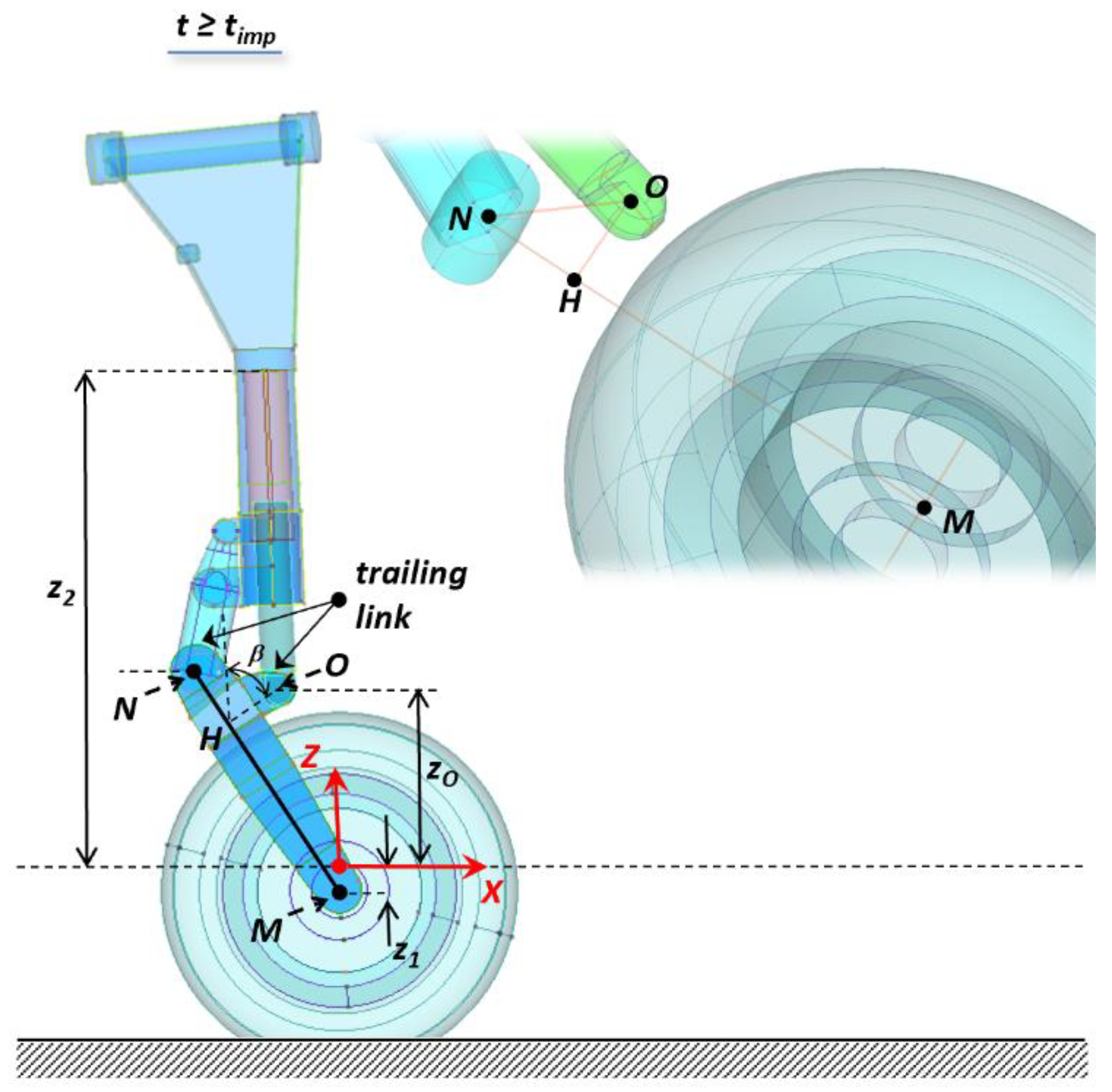
The vertical coordinate, z, of the generic point on segment located at a distance ε from M can be expressed as:
where zM and zN are the z-coordinates of M and N, while MN is the length of the segment .
If H indicates the projection of O on , then, it results at any instant of time:
with β denoting the angle between the segment and the normal to the ground passing through point H.
According to Equation (A1), the z-coordinate of the point H is equal to:
and, therefore, by substitution into Equation (A2), it can be obtained for z0:
Let N*, H*, and O* indicate the positions of the points N, H, and O at the instant of the impact; referring to the scheme of Figure A2, it can be observed that, at the generic instant of time t > tinp, the following applies:
Figure A2.
Reference scheme for the evaluation of the angle β.

Δα being the angle swept by the segment while rotating around M during the time interval [tinp: t].
Recalling some trigonometrical identities, may be rearranged as:
By taking in account Equations (A4) and (A5), Equation (A3) turns into:
and, finally, after the substitutions (see Figure A2):
Appendix B
The entire set of input data feeding the simulations addressed by this paper have been collected in the following tables.
The interested reader may refer to this appendix to get all the necessary information to reproduce and verify the proposed numerical method and related formulations.

Table A1.
Reference landing gear input data: geometric characteristics, inertial properties and stiffness along the x-axis
Table A1.
Reference landing gear input data: geometric characteristics, inertial properties and stiffness along the x-axis
| Parameter | Value |
|---|---|
| L0 | 0.165 m |
| L1 | 0.287 m |
| L2 | 0.401 m |
| L* | 0.330 m |
| R | 0.254 m |
| MN | 0.403 m |
| MH | 0.317 m |
| NH | 0.087 m |
| OH | 0.092 m |
| I | 0.52 Kg m2 |
| m | 36.84 |
| K | 6.3287 × 10⁵ N/m |
Table A2.
Tire mechanical properties (FPN vs. tire crushing at nominal inflation pressure).
| Tire Crushing (m) | FPN (N) |
|---|---|
| 0 | 0.00 |
| 0.001 | 390.12 |
| 0.002 | 796.10 |
| 0.003 | 1217.92 |
| 0.004 | 1655.60 |
| 0.005 | 2109.12 |
| 0.006 | 2578.49 |
| 0.007 | 3063.71 |
| 0.008 | 3564.78 |
| 0.009 | 4081.70 |
| 0.01 | 4614.47 |
| 0.02 | 10,813.88 |
| 0.03 | 18,598.23 |
| 0.04 | 27,967.52 |
| 0.05 | 38,921.75 |
| 0.06 | 51,460.92 |
| 0.07 | 65,585.03 |
| 0.08 | 73,241.44 |
Table A3.
Shock absorber main characteristics.
| Parameter | Value |
|---|---|
| A0 | 1.77 × 10⁻³ m2 |
| AS | 3.15 × 10⁴ m2 |
| P0 | 1.17 × 10⁶ Pa |
| cvisc | 0.70 N·s/m |
| ρoil | 920 Kg/m3 |
Table A4.
Dissipative force coefficient and pneumatic reaction vs. piston stroke.
| Piston Stroke [m] | [Ns2/m] * | Fa [N] |
|---|---|---|
| 0.000 | 5.96 × 10⁵ | 5.52 × 10⁻⁶ |
| 0.001 | 5.85 × 10⁵ | 5.57 × 10⁻⁶ |
| 0.004 | 5.35 × 10⁵ | 5.83 × 10⁻⁶ |
| 0.008 | 2.89 × 10⁵ | 7.93 × 10⁻⁶ |
| 0.009 | 2.57 × 10⁵ | 8.41 × 10⁻⁶ |
| 0.011 | 2.00 × 10⁵ | 9.54 × 10⁻⁶ |
| 0.014 | 1.59 × 10⁵ | 1.07 × 10⁻⁵ |
| 0.019 | 1.05 × 10⁵ | 1.31 × 10⁻⁵ |
| 0.021 | 8.07 × 10⁴ | 1.50 × 10⁻⁵ |
| 0.024 | 6.74 × 10⁴ | 1.64 × 10⁻⁵ |
| 0.026 | 5.52 × 10⁴ | 1.81 × 10⁻⁵ |
| 0.036 | 3.68 × 10⁴ | 2.22 × 10⁻⁵ |
| 0.041 | 3.68 × 10⁴ | 2.22 × 10⁻⁵ |
| 0.046 | 3.95 × 10⁴ | 2.15 × 10⁻⁵ |
| 0.051 | 5.29 × 10⁴ | 1.85 × 10⁻⁵ |
| 0.056 | 7.01 × 10⁴ | 1.61 × 10⁻⁵ |
| 0.059 | 8.39 × 10⁴ | 1.47 × 10⁻⁵ |
| 0.061 | 1.01 × 10⁵ | 1.34 × 10⁻⁵ |
| 0.064 | 1.43 × 10⁵ | 1.13 × 10⁻⁵ |
| 0.066 | 1.50 × 10⁵ | 1.10 × 10⁻⁵ |
| 0.069 | 1.55 × 10⁵ | 1.08 × 10⁻⁵ |
| 0.071 | 1.63 × 10⁵ | 1.05 × 10⁻⁵ |
| 0.081 | 1.95 × 10⁵ | 9.66 × 10⁻⁶ |
| 0.091 | 2.36 × 10⁵ | 8.77 × 10⁻⁶ |
| 0.101 | 2.80 × 10⁵ | 8.05 × 10⁻⁶ |
| 0.111 | 3.53 × 10⁵ | 7.17 × 10⁻⁶ |
| 0.121 | 4.54 × 10⁵ | 6.32 × 10⁻⁶ |
| 0.133 | 6.44 × 10⁵ | 5.31 × 10⁻⁶ |
* For each value in this column, the corresponding Atr may be obtained from Equation (4) Section 2.
Table A5.
Drop simulation settings (relevant data).
| Parameter | Value |
|---|---|
| h | 0.475 m |
| V0 | 45.28 m/s |
| M | 1520 Kg |
| Me | 1083 Kg |
| σ | 0.02 |
| μ | 0.75 |
References
- Young, D.W. Aircraft Landing Gears—The Past, Present and Future. Proc. Inst. Mech. Eng. Part D J. Automob. Eng. 1986, 200, 75–92. [Google Scholar] [CrossRef]
- EASA Part 66—Module 11.13—Landing Gear; European Union Aviation Safety Agency: Köln, Germany, 2015.
- FAA-H-8083-31A, Aviation Maintenance Technician Handbook—Airframe Vol. 2, U.S.; Department of Transportation, Federal Aviation Administration, Flight Standards Service: Washington, DC, USA, 2018.
- Hadekel, R. Shock absorber calculations. Aircr. Eng. 1940, 19, 71–73. [Google Scholar]
- Milwitzky, B.; Cook, F.E. Analysis of Landing-Gear Behavior; NACA Report 1154; Langley Field: Hampton, VA, USA, 1953; p. 45. [Google Scholar]
- Currey, N.S. Aircraft Landing Gear Design: Principles and Practices; AIAA Inc.: Marietta, GA, USA, 1988. [Google Scholar]
- Daniels, J.N. A Method for Landing Gear Modeling and Simulation with Experimental Data; NASA Contractor Report 201601; National Aeronautics and Space Administration, Langley Research Center: Hampton, VA, USA, 1996.
- Sivakumar, S.; Haran, A.P. Mathematical model and vibration analysis of aircraft with active landing gears. J. Vib. Control. 2015, 21, 229–245. [Google Scholar] [CrossRef]
- Sivakumar, S.; Haran, A.P. Aircraft random vibration analysis using active landing gears. J. Low Freq. Noise Vib. Active Control 2015, 34, 307–322. [Google Scholar] [CrossRef] [Green Version]
- Sivakumar, S.; Syedhaleem, M. Nonlinear vibration analysis of oleo pneumatic landing gear at touchdown impact. Math. Models Eng. 2018, 4, 89–97. [Google Scholar] [CrossRef]
- ABAQUS Software General Description Webpage. Available online: https://www.3ds.com/ (accessed on 26 February 2021).
- Park, I.K.; Kim, S.J.; Ahn, S.M. Spin-up, Spring-back Load Analysis of KC-100 Nose Landing Gear using Explicit Finite Element Method. J. Korean Soc. Aviat. Aeronaut. 2011, 19, 51–57. [Google Scholar]
- Kruger, W.R.; Moroandini, M. Numerical Simulation of Landing Gear Dynamics: State-of-the-art and Recent Developments. In Proceedings of the AVT-152 Symposium on Limit Cycle Oscillation and other Amplitude-Limited Self-Excited Vibrations, Loen, Norway, 5–8 May 2008. [Google Scholar]
- Lyle, K.H.; Jackson, K.E.; Fasanella, E.L. Simulation of aircraft landing gears with a nonlinear dynamic finite element code. J. Aircr. 2002, 39, 142–147. [Google Scholar] [CrossRef] [Green Version]
- Khapane, P.D. Gear walk instability studies using flexible multi-body dynamics simulation methods in Simpack. Aerosp. Sci. Technol. 2006, 10, 19–25. [Google Scholar] [CrossRef]
- Lernbeiss, R.; Plöch, M. Simulation model of an aircraft landing gear considering elastic properties of the shock absorber. J. Multi-Body Dyn. 2007, 221, 78–86. [Google Scholar] [CrossRef]
- Kong, J.P.; Lee, Y.S.; Han, J.D.; Ahn, O.S. Drop impact analysis of smart unmanned aerial vehicle (SUAV) landing gear and comparison with experimental data. Mater. Sci. Eng. Technol. 2009, 40, 192–197. [Google Scholar] [CrossRef]
- Xue, C.J.; Han, Y.; Qi, W.G.; Dai, J.H. Landing-Gear drop-test rig development and application for light airplanes. J. Aircr. 2012, 49, 2064–2076. [Google Scholar] [CrossRef]
- MATLAB Software General Description Webpage. Available online: https://www.mathworks.com/products/matlab.html (accessed on 26 February 2021).
- Carnahan, B.; Luther, H.A.; Wilkes, J.O. Applied Numerical Methods; John Wiley and Sons Inc.: NewYork, NY, USA, 1969; Chapter 6. [Google Scholar]
- STANAG 4671—Unmanned Aerial Vehicles Systems Airworthiness Requirements, 1st ed.; NATO Standardization Agency: Brussels, Belgium, 2009.
Figure 1.
Main types of landing gear: (a) cantilever strut [2] and (b) oleo-pneumatic shock-absorber [3].
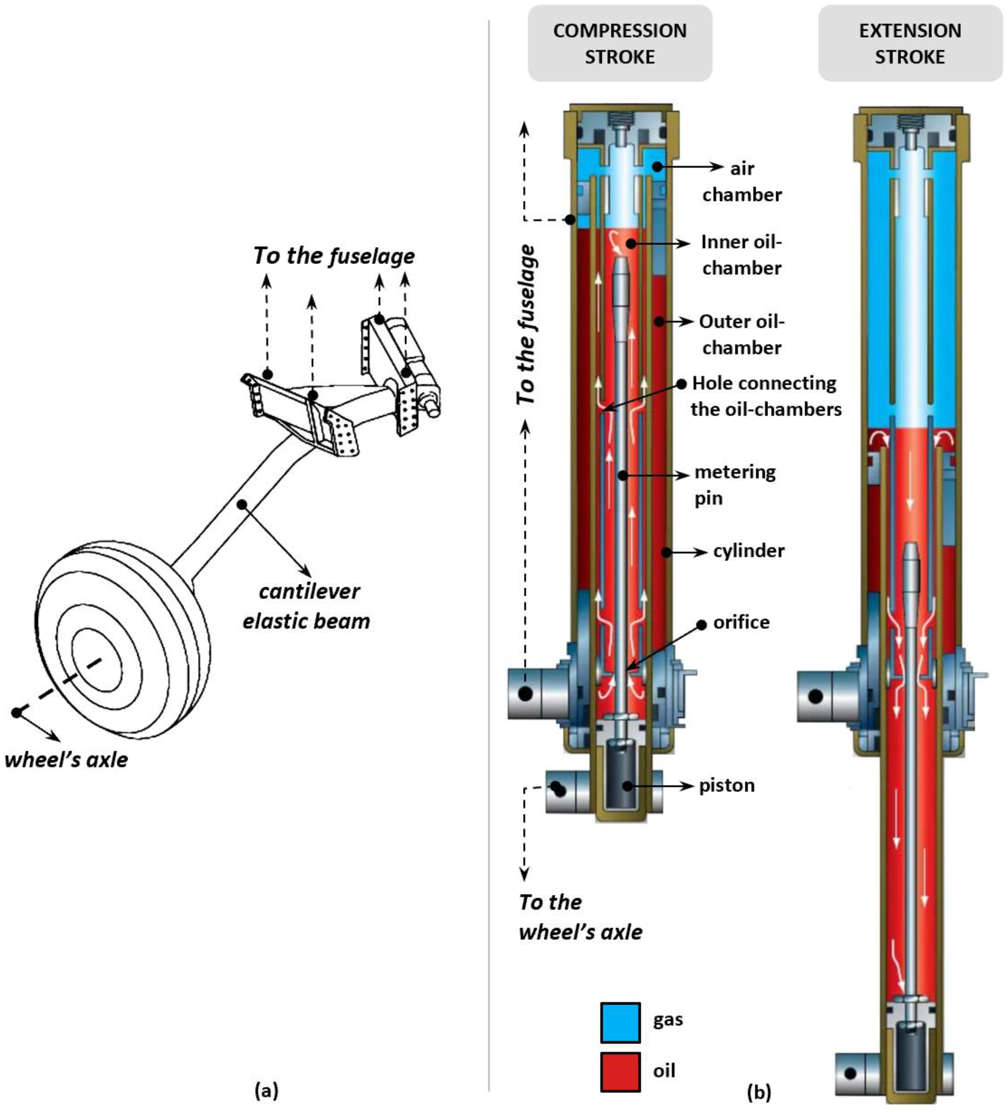
Figure 2.
Phases of landing gear drop and main parameters involved in impact dynamics.
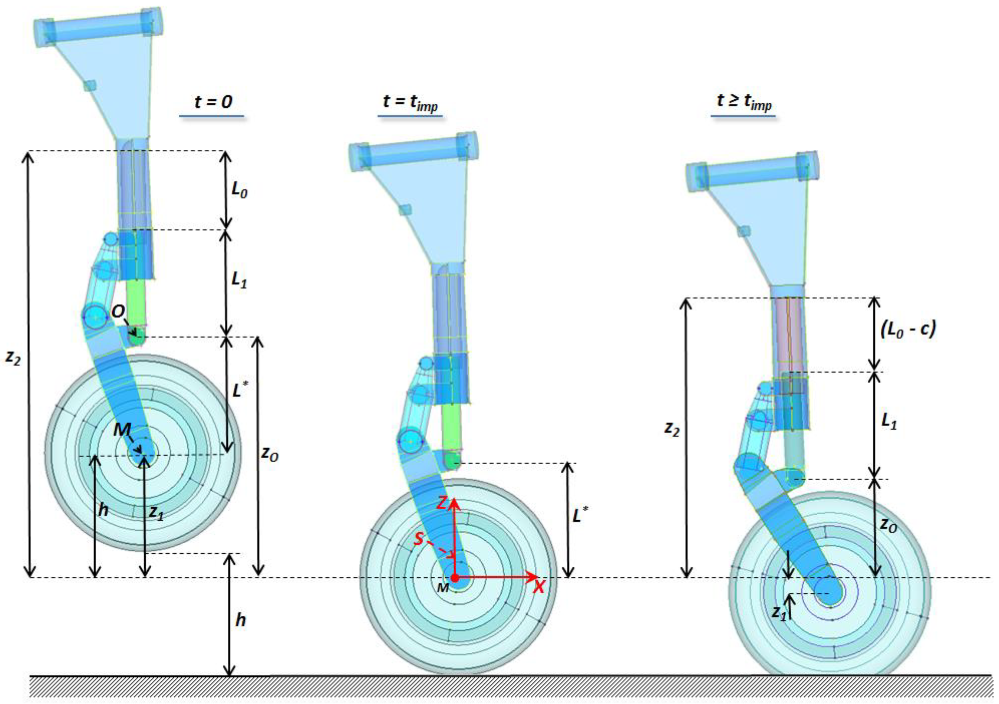
Figure 3.
Graphical sketch explaining relationships among variables s, x1, and φ.
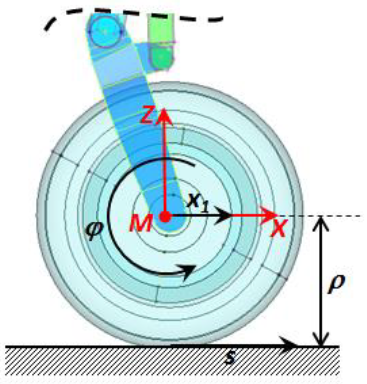
Figure 4.
Phases of landing gear drop and main parameters involved in impact dynamics (telescopic arrangement, typical of nose landing gear).
Figure 4.
Phases of landing gear drop and main parameters involved in impact dynamics (telescopic arrangement, typical of nose landing gear).
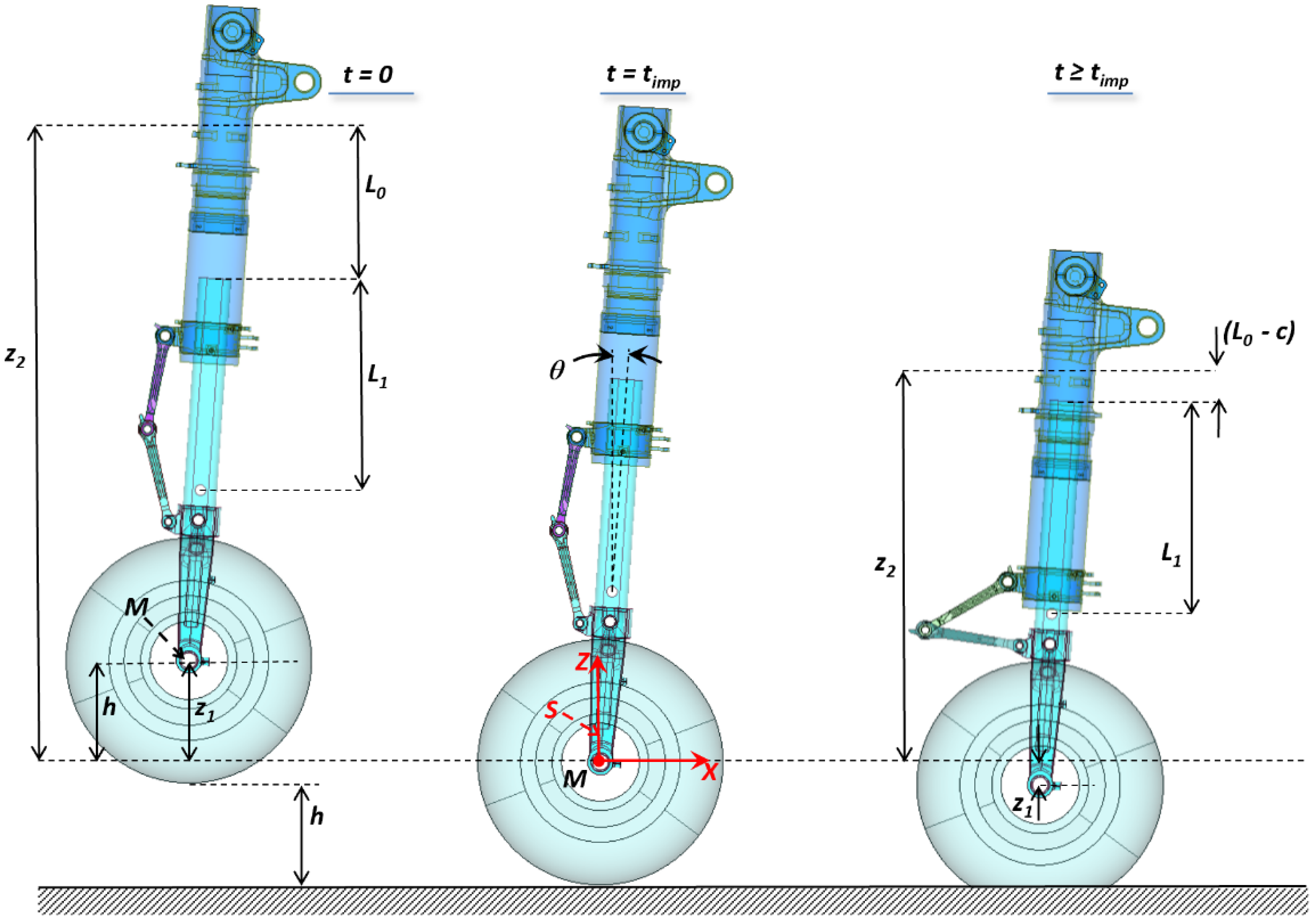
Figure 5.
Main modules and structure of drop test simulation tool.
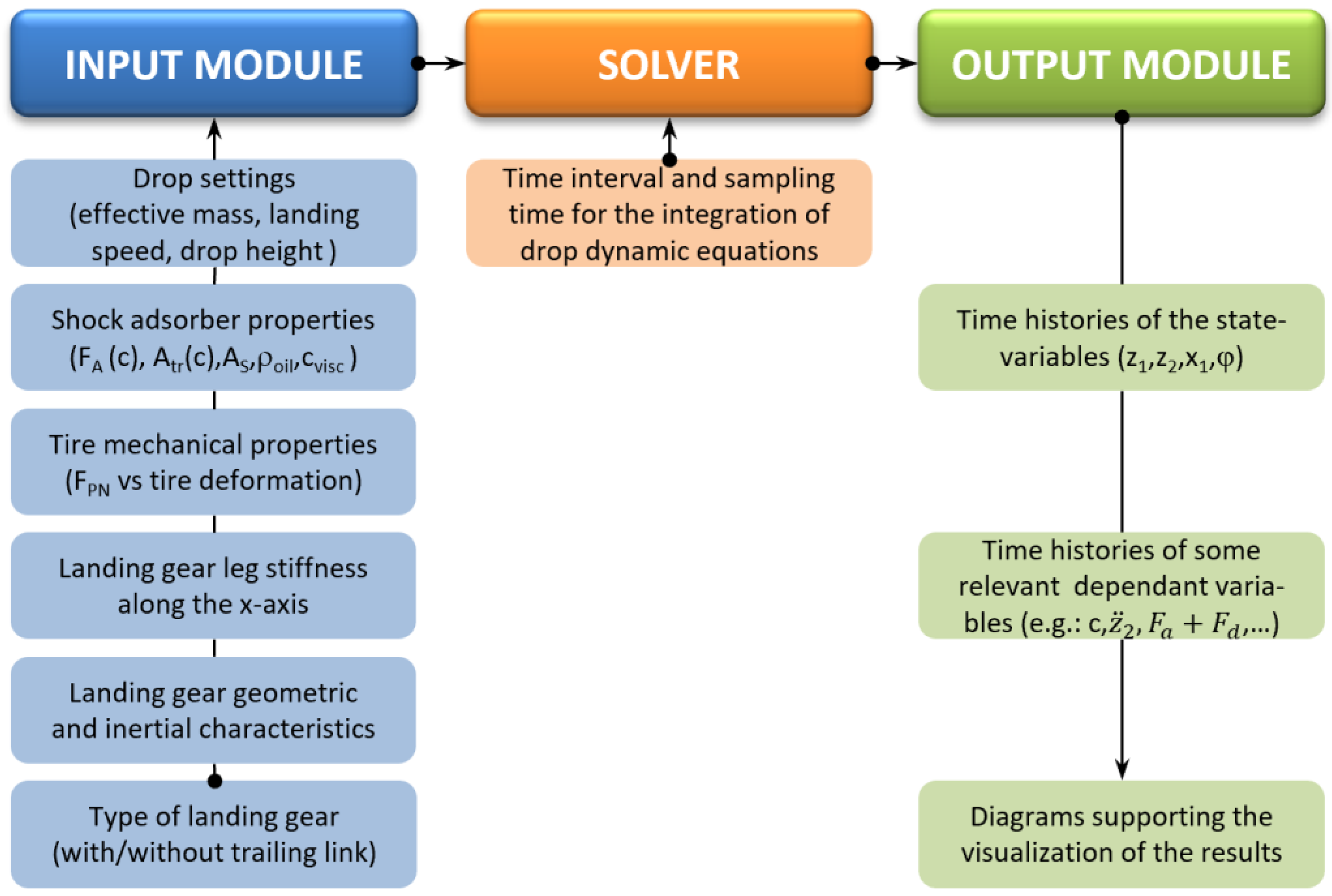
Figure 6.
Iterative process for determining effective mass: (a) trial drop tests and (b) numerical method.
Figure 6.
Iterative process for determining effective mass: (a) trial drop tests and (b) numerical method.
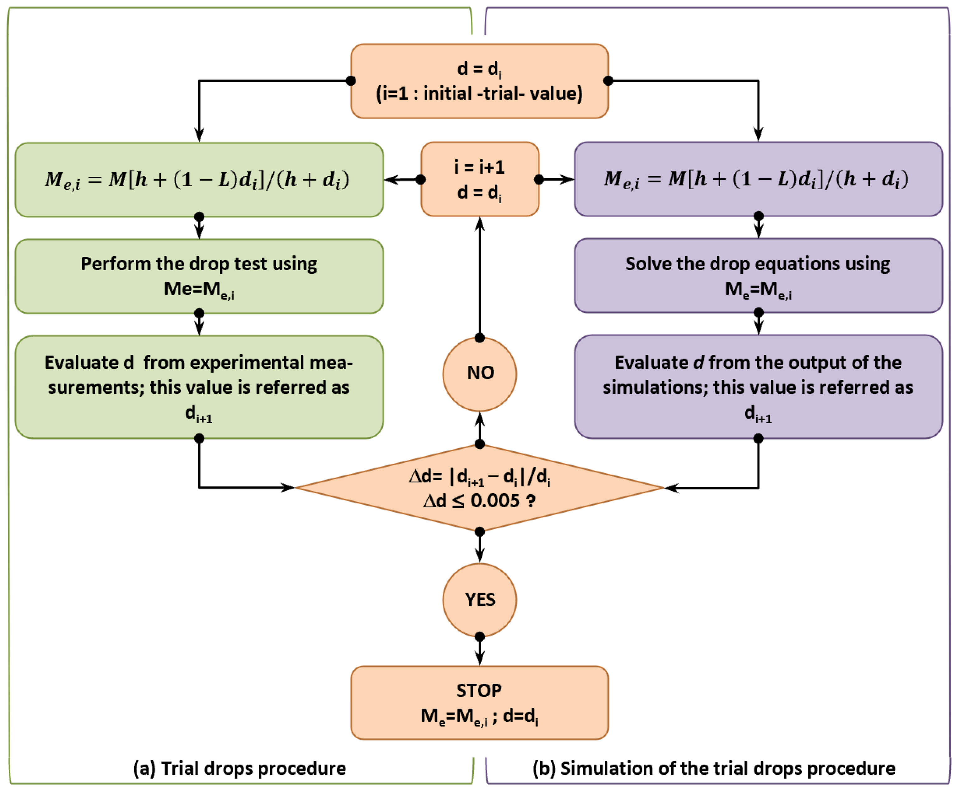
Figure 7.
Time histories of vertical displacements z1, z0, and z2.

Figure 8.
Time history of piston stroke.
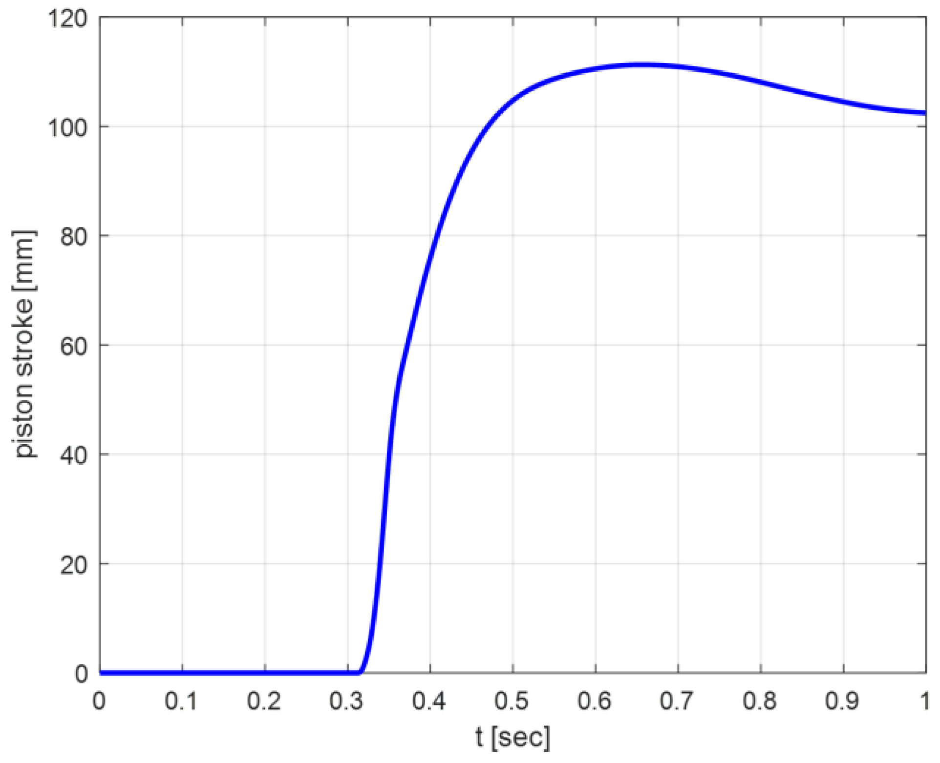
Figure 9.
Time history of effective mass acceleration along vertical axis.

Figure 10.
Time history of shock absorber total force (Fa + Fd).
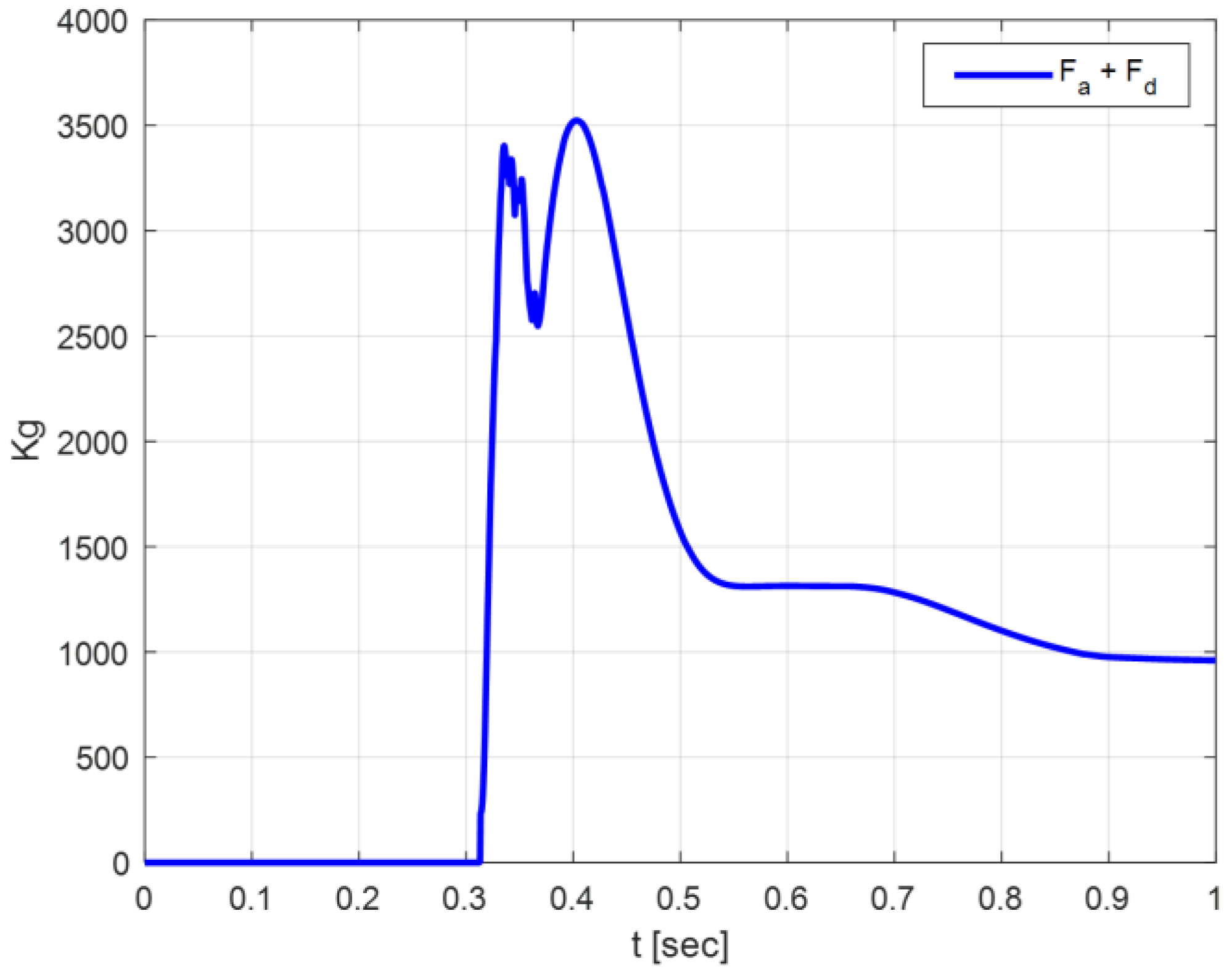
Figure 11.
Drop test arrangement (sketch).
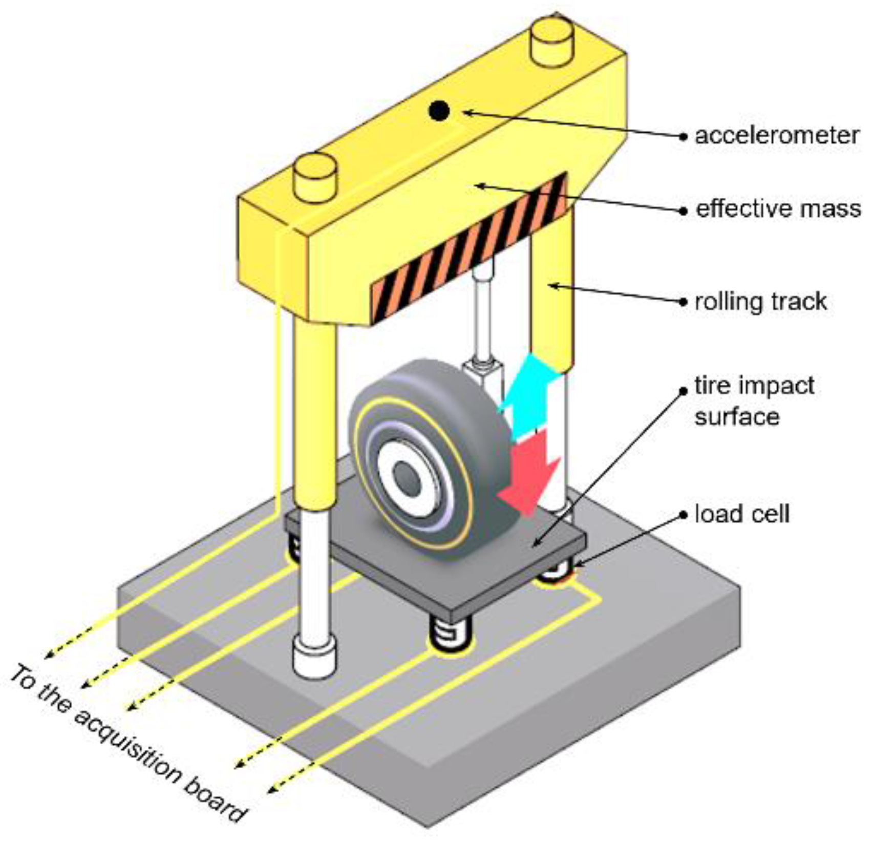
Figure 12.
Time history of vertical and horizontal forces at the hub.
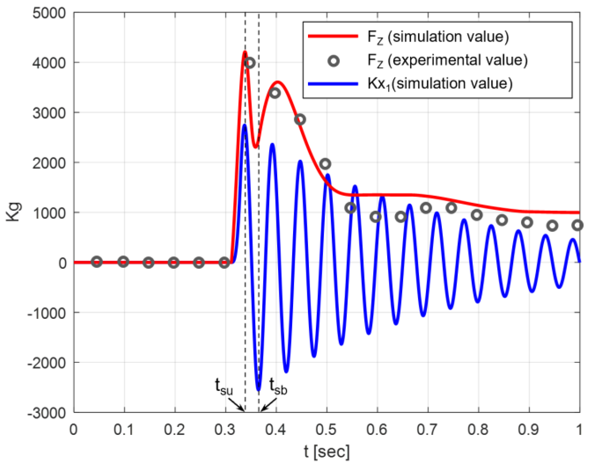
Table 1.
Initial conditions used for integration of drop dynamic equations.
| z1 (0) | = | h = 0.475 m (→ timp = (2 h/g)0.5 = 0.31 s) |
| z2 (0) | = | h + L*+ L1 + L0 = (0.475 + 0.329 + 0.287 + 0.165) = 1.256 m |
| = | 0 | |
| (0) | = | 0 |
| = | 0 | |
| = | 0 | |
| = | V0 = 45.276 m/s (landing speed, equal to 1.2·Vs0, where Vs0 is the aircraft stall speed with flaps down) | |
| = | V0/R = 154.65 rad/s, where R is the nominal radius of the tire (equal to 0.254 m for the reference gear unit) |
Publisher’s Note: MDPI stays neutral with regard to jurisdictional claims in published maps and institutional affiliations. |
© 2021 by the author. Licensee MDPI, Basel, Switzerland. This article is an open access article distributed under the terms and conditions of the Creative Commons Attribution (CC BY) license (https://creativecommons.org/licenses/by/4.0/).
Share and Cite
MDPI and ACS Style
Pecora, R. A Rational Numerical Method for Simulation of Drop-Impact Dynamics of Oleo-Pneumatic Landing Gear. Appl. Sci. 2021, 11, 4136. https://doi.org/10.3390/app11094136
AMA Style
Pecora R. A Rational Numerical Method for Simulation of Drop-Impact Dynamics of Oleo-Pneumatic Landing Gear. Applied Sciences. 2021; 11(9):4136. https://doi.org/10.3390/app11094136
Chicago/Turabian StylePecora, Rosario. 2021. "A Rational Numerical Method for Simulation of Drop-Impact Dynamics of Oleo-Pneumatic Landing Gear" Applied Sciences 11, no. 9: 4136. https://doi.org/10.3390/app11094136
Note that from the first issue of 2016, this journal uses article numbers instead of page numbers. See further details here.