Article

Turn-to-Turn Fault Diagnosis on Three-Phase Power Transformer Using Hybrid Detection Algorithm

by
Chien-Hsun Liu
,
Willybrordus H. P. Muda
and
Cheng-Chien Kuo
*
Electrical Engineering Department, National Taiwan University of Science and Technology, Keelung Rd, Da’an District, Taipei City 10607, Taiwan
*
Author to whom correspondence should be addressed.
Appl. Sci. 2021, 11(6), 2608; https://doi.org/10.3390/app11062608
Submission received: 21 February 2021 / Revised: 7 March 2021 / Accepted: 9 March 2021 / Published: 15 March 2021
(This article belongs to the Section Electrical, Electronics and Communications Engineering)

Abstract

:
A power transformer (PT) in power generation or transmission is critical to maintaining electrical continuity. Fault detection on a PT is needed, especially of incipient faults, which are often caused by a turn-to-turn fault (TTF) before it develops into a more severe fault. We use a hybrid algorithm between conventional and modern techniques to detect a developing fault in a PT. The current response signals from a negative sequence current directional algorithm, extended park vector algorithm (EPVA), differential negative sequence current, and EPVA-fuzzy system are combined to distinguish the possibility of a TTF. The subalgorithms are combined using a hybrid detection algorithm to distinguish the faults. The model is a 10 MVA, three-phase PT with Δ-Y configuration 150/300 kV, simulated using MATLAB Simulink software. The results show that by combining the subalgorithms, several limitations are distinguished within the TTF with a slight increase in accuracy.

1. Introduction

Power transformers (PTs) are essential to maintain the stable operation of a power grid. There is a massive number of transformers in service, and internal faults occur in the long-term ageing process [1]. However, conducting maintenance with system outage or assessment of the transformer means considering the expenditure and time due to production loss. Energize levels at 765 kV, and even 400 kV, can generate inrush currents which can cause internal PT damage. There are several protection schemes required for effective discrimination between an internal fault and inrush [2].
The faulty components need to be fixed quickly as they can cause severe damage, loss, and power stability problems. Outages resulting from a fault in PTs cause significant revenue loss and affect consumer service. Therefore, online PT monitoring is needed to avoid these outages. If the faults are not detected, they will develop into more severe faults. Thus, detection of inter-turn faults is a concern in power systems [3,4]. The result of a transformer failure survey, based on the investigation of 750 massive transformer failures from 1996 to 2010, confirmed the importance of short-circuit strength as almost half of the failures were correlated to winding and the insulating system [5,6]. Accounting for transformer winding connections is required to apply differential protection principles to PTs. Concerning transformers of standard winding connections, these protection rules are commonly referred to as ratio matching, vector group compensation, and zero-sequence removal. The standard protection method is the differential protection current between the line-to-line. The protection method is used for protecting power transformers of 10 MVA and above [7].
However, the differential protection provides accurate results in most of the fault cases, and it suffers from the problem of accidental tripping during external events such as magnetizing inrush conditions [8]. The percentage differential scheme is used to restrain the second harmonic component, and sometimes the fifth harmonic component, to avoid accidental tripping against magnetizing inrush conditions [2,9]. Another problem when using conventional differential protection is the detection of the low-level winding turn-to-turn fault (TTF). If this fault happens, the terminal current is relatively unchanged, and the circulating current in the short turn area will increase and be dangerous. This protection only detects if the differential current exceeds 20% to 25% of the rated current [10].
Many methods are used to detect TTFs in PT windings. Solutions include optimization of the PT’s estimation parameter problem [11,12,13,14] and an artificial base using neural networks [15,16] to detect TTFs. The optimization technique searches for the optimal PT parameter. Ouyang et al. [17] applied the parameter identification of a transformer based on the PSO algorithm using port data. In this research, the internal transformer fault can be determined according to the model reference adaptive principle. The fitness function consists of the two models’ response performance, and its corresponding circuit parameters are calculated using the PSO algorithm. The PSO algorithm is used to obtain the optimum value from the model’s equivalent parameters and converge. The optimal parameter obtained from the optimization process is the equivalent parameter in the model to be identified. However, using the optimization method has a higher computational burden than using the analog signal-based method (terminal current signal).
The negative sequence current scheme could be an alternative for fault detection and distinguish between an internal (TTF) and an external fault. The negative sequence current is a simple and efficient protection technique to detect minor internal TTFs in PTs. According to [10] and [7], the negative sequence detects TTFs involving 1% transformer winding. However, the negative sequence current algorithm cannot distinguish when an external and internal fault occur simultaneously. The extended park vector algorithm (EPVA) method can detect and distinguish turn-to-turn winding insulation failures from magnetizing inrush current transients. The EPVA also overcomes the limitation of the negative sequence current algorithm. The EPVA is not affected by the external fault and can detect the TTF accurately.
Fuzzy logic was developed to detect TTFs in a transformer. Here, fuzzy logic is employed to monitor the transformer’s condition and improve the protection system’s performance. Using fuzzy logic overcomes the traditional PT differential scheme’s limitations by detecting a low-level TTF. The fuzzy-based technique is simple, robust, and able to detect incipient faults at an early stage [4], and shows a fast and accurate trip operation [18]. The fuzzy algorithm also improves the accuracy of the diagnosis and the efficiency of transformer maintenance [19]. A combination technique using fuzzy logic and Clark’s transform was used to improve the differential protection performance [20]. A TTF may occur even if no current is flowing on one side of the transformer during energization. With no current flowing in the secondary windings of the transformer, negative-sequence current-based algorithms become insensitive.
This paper discusses a voting algorithm that is a combination of several protection algorithms and used to make the right decision for fault detection. The algorithms used are the negative-sequence directional algorithm, EPVA, differential negative-sequence algorithm, and the fuzzy Mamdani conventional protective algorithm. According to the simulation, each algorithm detects whether the fault belongs to an internal or external fault. The results from each algorithm were collected, and we calculated how many possibilities of internal fault and external fault happened.
Section 2 of this paper introduces the turn-to-turn equivalent circuit and transformer configuration. Section 3 discusses the purpose and method to detect and distinguish PT faults. Section 4 shows the results and discussion of the TTF simulation in a PT for a 1% turn fault, followed by an external fault. Section 5 concludes the research.

2. Hybrid Algorithm in TTF Diagnosis System

The hybrid algorithm’s aim is to create a fault detection system in a PT, especially for TTF recognition. The algorithm uses a terminal current as an input and generates a condition state of a PT regarding the TTF. The algorithm’s output can be used as a supporting tool to monitor a TTF inside a PT while not connected to the protection breaker of the PT. In this research, we simulated the proposed algorithm into a PT model using MATLAB Simulink. This algorithm combined and obtained results from the subalgorithms (Figure 1b) to obtain the PT’s final condition fault status.
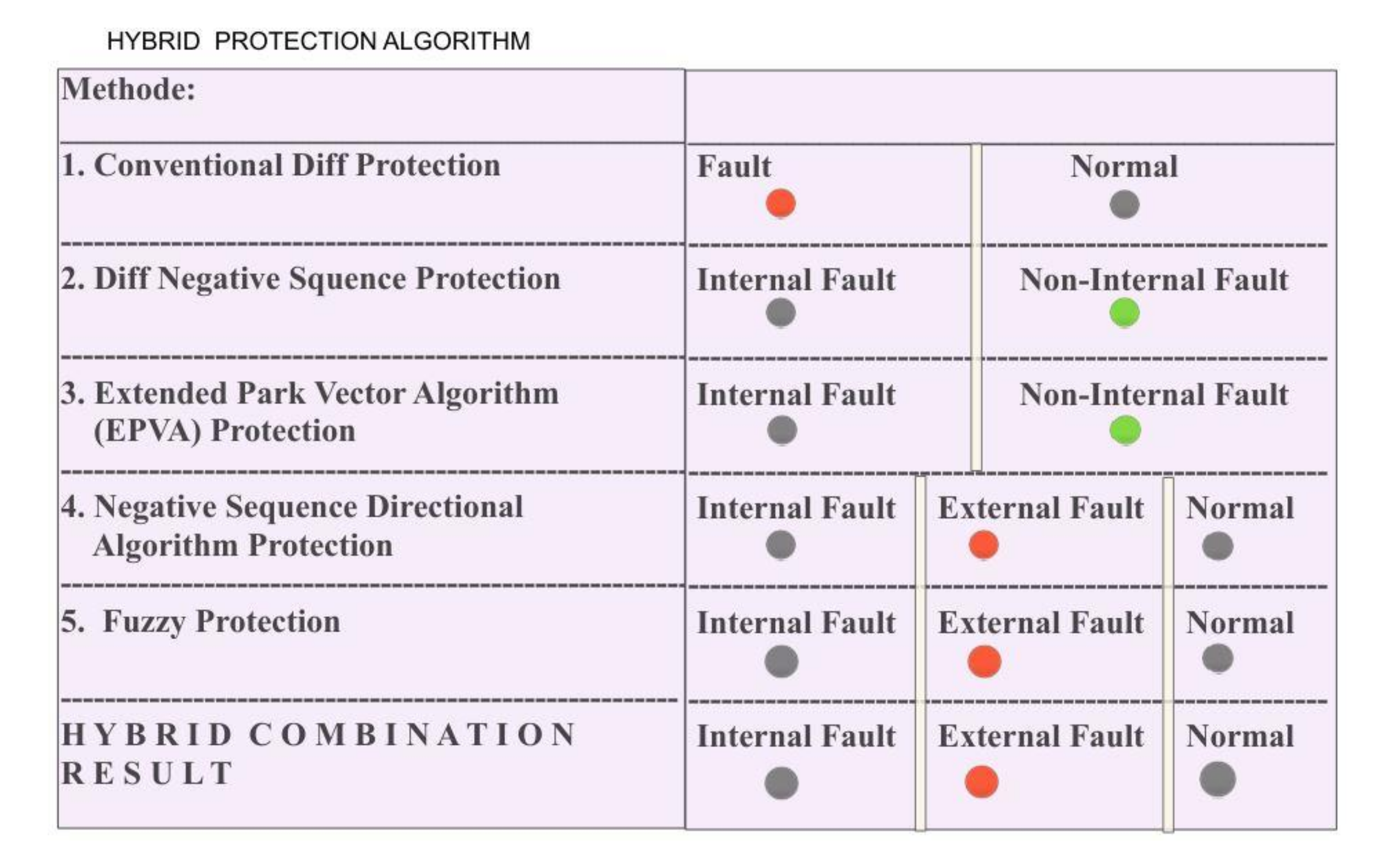
The sub algorithms are the conventional differential protection, negative-sequence directional algorithm, EPVA, negative differential sequence, and fuzzy EPVA algorithm. Each has a different role in PT fault diagnosis and generates different decisions (internal fault, external fault, and normal condition).
The conventional differential protection can detect fault if the difference value of the phase current between primary and secondary winding is higher than the threshold value. This protection only detects a fault or normal state and is incapable of distinguishing the type of fault, either internal or external. The negative sequence directional algorithm and fuzzy logic detect three states of a PT’s condition. Both can detect internal faults, which, in this case, was caused by a TTF.
The differential negative sequence and EPVA only detect internal and noninternal fault states. The hybrid algorithm protection decides the internal, external, or normal conditions based on each sub algorithm’s result. The hybrid algorithm chooses the most detected condition, which is generated by the sub algorithms.
This method is used to distinguish the weaknesses for each sub algorithm. The conventional differential protection is unable to distinguish if a fault in the transformer, either an internal or external fault, occurs. This algorithm is not sensitive enough to detect low-level TTFs inside the transformer [3]. The negative-sequence directional algorithm can detect a TTF when external and internal faults occur simultaneously [10]. The differential negative sequence and EPVA only detect the internal fault and non-internal fault conditions. When there is an external fault, the algorithm detects a non-internal fault, which is the same as in the normal condition. The internal fault will decide if there are more than or equal to two internal fault states (nif), declared by the sub algorithm. This rule also applies to the external fault state (nef). The external fault will declare if there are more than two external fault statuses. A noninternal fault in the differential negative sequence protection and EPVA could indicate an external fault or a normal condition. A normal condition is decided if all sub algorithms declare a normal condition and a non-internal fault condition for the differential negative sequence protection and EPVA. The rule for the hybrid detection algorithm is expressed in Equation (1). Principally, the hybrid detection algorithm declares a transformer condition based on sub algorithm results. The interface from the hybrid algorithm detection is shown in Figure 1a.
PT   Fault   Condition   =   Internal   fault ,   n if 2 External   fault ,   n ef 2 Normal ,   n fault = 0

2.1. Conventional Differential Protection

The first sub algorithm is the conventional differential protection. This protection is a conventional method, which measures the differential current between the primary and secondary side for each phase. This protection is unit-type for a specified zone or piece of equipment. It is only in the case of faults to the zone that the differential current (the difference between input and output currents) is high [21]. Differential protection schemes are mainly used for protection against phase-to-phase faults and phase-to-earth faults. Typically, the operating coil carries no current as they are balanced on both of the PT’s sides. When the fault occurs in the PT windings, the balance is disturbed. The differential relay’s operating coils carry a current corresponding to the different current among the transformers’ two sides. Thus, the relay trips the main circuit breakers on both sides of the PT. The first sub algorithm is mainly used to distinguish between the normal and external fault conditions in a PT.

2.2. Negative Sequence Directional Algorithm

The second sub algorithm is the negative-sequence directional algorithm. This algorithm uses an asymmetrical component from a 3-phase current principle to detect a fault, especially a TTF. When there is a fault, either internal or external, the current phase will not be symmetric or phasors become unbalanced. An unbalanced phasor generates positive (I1), negative (I2), and zero (I0) sequence components, which are members of the balance set. The 3-phase currents from the primary and secondary side are extracted by the discrete Fourier transform algorithm. The symmetrical components determined by applying the Fortescue transformation are presented in Equation (3). The unbalance current can be expressed as the sum of their components, as shown in Equation (2).
I a = I b = I c = I 0 + I 1 + I 2 I 0 + a 2 I 1 + aI 2 I 0 + aI 1 + a 2 I 2
A phase rotation operator (a) is defined to rotate a phasor vector. Phases are rotated forward by 120°. Conversely, the phase currents’ sequence components can be written as Equation (2) [22].
I 0 = 1 3 I a + I b + I c I 1 = 1 3 I a + aI b + a 2 I c I 2 = 1 3 I a + a 2 I b + aI c
The negative sequence current (I2) will increase if there is an unbalanced phasor or fault. If the value exceeds a predefined threshold with a typical default of 4% of the rated current, the angle between them is compared. When a different angle (ϕ2TH) is between a predefined directional limit, typically from ±60° to ±85° [10], the internal fault is detected. Otherwise, it is an external fault (Figure 2). The second subalgorithm is used for distinguishing between internal and external faults and normal condition.

2.3. EPVA

The third sub algorithm is the EPVA, which is based on a space vector transformation. A space vector transformation describes the three-phase systems’ behavior and was applied to the PT’s differential protection. The EPVA is based on the spectral analysis of the differential current Park’s vector modulus AC level.
The three-phase quantities are changed into a synchronous rotating reference frame using the ABC–DQ transformation [23]. The direct and quadrature current from Park’s vector components (ID, IQ) are obtained by the Park transformation using Equation (5) [10], where ida, idb, and idc denote the differential current for each phase. The current is used as inputs for calculating ID and IQ.
i dA i dB i dC = i LA i LB i LC + N s N p 1 0 1 1 1 0 0 1 1 i La i Lb i Lc
I D I Q = 2 3 1 6 1 6 0 1 2 1 2 i dA i dB i dC
i EPVA = i D + i Q = i D 2 + i Q 2
The DC level i EPVA is obtained using Equation (6). The EPVA current is proportional to the balanced three-phase current system (conditions A and B in Figure 3). An incipient winding fault leads to an increase in the magnitude of the differential current of the affected phase compared with a healthy situation, which results in an unbalanced three-phase currents system (condition C in Figure 3). Under these conditions, the differential current Park’s vector modulus contains a DC level and an AC level at twice the supply frequency (2f) [24,25]. The subalgorithm EPVA technique in this research is used to distinguish between internal fault and normal condition.

2.4. Differential Negative-Sequence Protection

The fourth sub algorithm is the differential negative sequence protection. The application of the negative-sequence algorithm for the protection of PTs has attracted great attention in the last years and several variants of the method have been proposed. This algorithm measures the different values of the negative-sequence current over a finite time. During an internal fault, the negative current sequence generates a current and the differential current (3) increases so the differential current and negative-sequence current can fuse. This algorithm uses the differential current (refer to Equation (4)) to obtain a negative-sequence component using Equation (3). The inputs from Equation (3) are substituted by the differential current value for each phase. The differential negative sequence can be expressed as Equation (7).
I d 2 = 1 2 I da + a 2 I db + aI dc

2.5. Fuzzy EPVA

The fuzzy inference system is a process that works using a parallel method. There is no data loss during the process because of this property. The fault detection generates more precise results than conventional relaying techniques [18]. The fuzzy inference collects and processes data, mapping from a given input to an output, using fuzzy logic. All the rules are evaluated in parallel using fuzzy reasoning using the differential current and EPVA current as inputs to the fuzzy system (Figure 4). The two inputs are processed inside the fuzzy logic system to generate a crisp value or output score for each fault (internal and external). This scoring system can indicate which fault occurred inside a PT.
Inside the fuzzy logic system are three parts: fuzzification, inference system, and de-fuzzification. Fuzzification is used to convert the measured quantities from the process (voltages, velocities, temperatures, etc.) into fuzzy sets used by the inference stage. Each input, either the EPVA current or the differential current, uses a trapezoidal form as its function with three levels (low, medium, and high). The membership function for the output value (internal and external fault) uses a Gaussian bell function with three values: incipient fault (IF), medium fault (MF), and severe fault (SF). The inference system is a process to determine each rule’s degree of firing in the rule base. The inference stage’s second function is to determine the degree to which each rule’s recommendation is weighted when arriving at the final decision, and to decide an implied fuzzy set corresponding to each rule. The number of fuzzy inference rules for the proposed system is 15, as shown in Figure 5. The defuzzification stage converts the collection of recommendations of the rules into a crisp output. The centroid is used as a defuzzification stage in Equation (8) [26], where DV signifies defuzzification value; and xi, and μ(xi) are inputs and the membership function value, respectively. If the DV from the internal fault is greater than the external fault, the decision is generated as an internal fault. However, if the DV from the internal fault is less than an external fault, the decision is generated as an external fault.
DV = i = 0 n x i μ ( x i ) i = 0 n μ ( x i )

3. Simulation Setup

We developed a turn-to-turn fault simulation on a 10 MVA, three-phase, power transformer with Δ-Y configuration of 150/300 kV. For the simulation, we used the SIMSCAPE module on MATLAB. When developing the turn-to-turn fault simulation, the shorting resistor was used to simulate the short turn in a primary winding on phase A. The short-circuited turns act as an autotransformer load on the winding, where Rsh represents the fault impedance [3].
The configuration model is shown in Figure 6, and the equivalent short circuit is shown in Figure 7. The distribution of the magnetic flux is fundamentally altered by the transformer with an internal turn-to-turn fault. An exciting current is required to produce the magnetic flux in the core. The exciting current flows in the primary winding, where it establishes an altering flux in the magnetic circuit. When an internal turn-to-turn fault occurs, the situation is more complex [22].

4. Simulation and Comparative Analysis

The following figures show the simulation results regarding the turn fault, external fault, and normal scheme. Differential current and line current signals were collected from the simulation data. Those signals became the input for the sub algorithms, while the hybrid detection algorithm decided the final condition based on the sub algorithms results.

4.1. Turn-to-Turn Fault Scheme

In this scheme, the fault happened at t = 3 s. The number of short turns on the primary winding varied between 0.8% and 16% from the total winding turn. The turn-to-turn fault did not make a difference in the terminal current of PT or voltage while in primary or secondary current (see Figure 8). Therefore, the conventional differential protection algorithm failed to detect this kind of fault. In the early stage of the short turn level, the conventional algorithm was incapable of detecting the fault because the differential current was too small and did not exceed the predefined threshold value. The conventional algorithm was also unable to distinguish whether the fault caused by an internal or external fault.
The negative-sequence directional algorithm can give a correct decision when the TTF occurs. When the turn-to-turn fault occurred, the negative -sequence current in the primary side (Ip2) increased significantly and increased slightly on the secondary side (Is2) (see Figure 9). The phase difference between the negative sequence current in the primary and secondary side decreased to between +60° and +85° like in Figure 10. So that the negative sequence directional algorithm declares internal fault. EPVA current (iepva) rose to 104.8 A (see Figure 11), and the differential negative sequence current increased to 85.55 A (see Figure 12). The result for the EPVA and differential negative sequence algorithm showed the correct result to decide the fault. However, these algorithms cannot distinguish between normal and external fault conditions discussed in the external scheme.
For comparison, the result table shows that in the early stage of the TTF, with a 0.8 and 1.6% short turns level, the EPVA and differential negative sequence current were more sensitive to detecting the fault. The fuzzy algorithm showed that the internal fault crisp value was more significant than the external fault (see Figure 13). The internal fault crisp value was 1559, and the external fault crisp value was 53.42. Based on the result, the fuzzy algorithm declared an internal fault state at the 1.6% turns-to-turns short level.
Three of the sub algorithms were internal faults, and one was a normal condition at 1.6% short turns level. At the 0.8% short turns level, two sub algorithms were internal faults, and another was normal condition. Hence, the hybrid detection algorithm set an internal fault as the final decision for both levels. Four sub algorithms were declared as an internal fault when the turn-to-turn level reached 2.4%. The hybrid detection algorithm decided to set an internal fault as the result. In this case, the hybrid algorithm overcame wrong decisions from several sub algorithms and gave a correct result. The internal fault condition was declared as the result by the hybrid detection algorithm based on the sub algorithm result (see Figure 14). The summary of the results of the experiment is shown in Figure 15.

4.2. External Fault Scheme

In this scheme, the external fault happened at t = 3 s in the secondary side phase A. The external fault was simulated with a short line between the line-to-line and line-to-ground in the secondary side. The resistor was used to mimic the short circuit in the simulation, with several values (50, 100, 500, 600, 700, and 800 ohms). The external fault condition created a massive differential current. The primary and secondary current on the terminal voltage (see in Figure 16) showed a significant difference before and after the fault. The conventional differential protection detected the external fault because the differential current between the primary and secondary sides exceeded the limit as shown in Figure 17. The phase difference between the primary and secondary negative sequence current also stayed above 85°.The external fault scheme, the negative sequence current from the primary (Ip2) and secondary (Is2) side, rose significantly. The phase difference between both sides stabilized at 118° (see in Figure 18). Based on that, the directional algorithm was declared an external fault condition.
The EPVA and differential negative-sequence algorithm were unable to distinguish between a normal and an external fault. When an external fault happened, iepva, the differential negative sequence current did not increase or exceed the threshold value. Therefore, the transformer condition was declared as a non-internal fault. However, this condition also occurred at normal conditions, as shown in Figure 19 and Figure 20. The fuzzy algorithm generated a crisp external value more significant than the crisp internal value. The internal and external fault crisp values were 15.26 and 7918, respectively like shown in Figure 21. Therefore, the fuzzy algorithm generated the external fault status.
This limitation can be overcome by the negative-sequence directional algorithm, conventional differential protection, and fuzzy algorithm, where three sub algorithms detect the external fault. Therefore, the hybrid detection algorithm chooses an external fault as the result. The hybrid detection algorithm generated the correct result about the transformer condition in the external fault scheme (see in Figure 22). The summary of the results is shown as either the sub algorithms or the hybrid algorithm that declared the external fault status at the PT (see in Figure 23).

4.3. Normal Scheme

In this scheme, we simulated a normal transformer condition with a variation in the load. This scheme aimed to ensure the protection of the algorithm to generate correct results in a normal condition. The summary result (see Figure 24) showed that the hybrid detection algorithm was declared a normal state in a normal scheme. All sub algorithm and hybrid algorithm declared non internal fault or normal status like shown in Figure 25. Using the hybrid detection algorithm increases accuracy more than using a single algorithm (see Figure 26). The fuzzy algorithm generated the sub algorithm’s highest accuracy, 98%, when distinguishing between a fault and normal condition (accuracy one). Accuracy two distinguished between the internal and non-internal fault. The highest accuracy of the sub algorithm occurred in the differential negative sequence and EPVA. Accuracy three distinguished between internal, external, and normal conditions, where the highest accuracy of the sub algorithm occurred on the fuzzy algorithm. The fuzzy algorithm was useful in detecting the fault and distinguishing between an internal or external fault. Additionally, using the fuzzy algorithm requires the experience to design the inference rule and membership function for input or output, where the design can be different for other types of transformers. However, a hybrid detection algorithm can overcome the misdetection of the fuzzy algorithm and increase fault detection accuracy.

5. Conclusions

The hybrid algorithm protection’s objective is to minimize the misdiagnosis status generated by each sub algorithm regarding a PT’s condition. The algorithm declares a fault condition based on the results from the sub algorithms. The algorithm’s application is safe and simple and will not change the existing electrical system since its output is not connected to any circuit breaker protection. Based on the simulation result, the hybrid algorithm can detect incipient TTF until the 0.8% short-turn level, and increase the accuracy of TTF detection. In our simulation results for the TTF case, the hybrid algorithm detected the internal fault case in all the short-turn levels.
In this research, we only applied our proposed algorithm to a three-phase PT using a MATLAB Simulink model and a terminal current signal as an input. Hence, external factors such as temperature inside the PT, oil pressure, and other environmental aspects were not considered as an input for our system. Referring to the limitation issue, future research is needed to improve the methods for protecting PT.

Author Contributions

Conceptualization, methodology, W.H.P.M., software and validation, W.H.P.M.; formal analysis, W.H.P.M., and C.-H.L.; writing—review and editing, W.H.P.M. and C.-H.L.; supervision, C.-C.K. All authors have read and agreed to the published version of the manuscript.

Funding

This researched receive no external funding.

Institutional Review Board Statement

Not applicable.

Informed Consent Statement

Not applicable.

Data Availability Statement

Not applicable.

Conflicts of Interest

The authors declare no conflict of interest.

References

  1. Liu, Y.; Song, B.; Wang, L.; Gao, J.; Xu, R. Power Transformer Fault Diagnosis Based on Dissolved Gas Analysis by Correlation Coefficient-DBSCAN. Appl. Sci. 2020, 10, 4440. [Google Scholar] [CrossRef]
  2. Shah, A.M.; Bhalja, B.R. Fault discrimination scheme for power transformer using random forest technique. IET Gener. Transm. Distrib. 2016, 10, 1431–1439. [Google Scholar] [CrossRef]
  3. Oliveira, L.M.R.; Cardoso, A.J.M. Power transformers behavior under the occurrence of inrush currents and turn-to-turn winding insulation faults. In Proceedings of the XIX International Conference on Electrical Machines–ICEM 2010, Rome, Italy, 6–8 September 2010; pp. 1–7. [Google Scholar]
  4. Ramesh, K.; Sushama, M. Inter-turn fault detection in power transformer using fuzzy logic. In Proceedings of the 2014 International Conference on Science Engineering and Management Research (ICSEMR), Chennai, India, 27–29 November 2014; pp. 1–5. [Google Scholar]
  5. Geiβler, D.H. Short-Circuit Withstand Capability of Power Transformers; Cuvillier Verlag: Göttingen, Germany, 2015. [Google Scholar]
  6. Gouda, O.E.; Dein, A.Z.E.; Moukhtar, I. Turn-to-earth fault modelling of power transformer based on symmetrical components. IET Gener. Transm. Distrib. 2013, 7, 709–716. [Google Scholar] [CrossRef]
  7. Kasztenny, B.; Thompson, M.; Fischer, N. Fundamentals of short-circuit protection for transformers. In Proceedings of the 2010 63rd Annual Conference for Protective Relay Engineers, College Station, TX, USA, 29 March–1 April 2010; pp. 1–13. [Google Scholar]
  8. Shah, A.M.; Bhalja, B.R.; Patel, R.M. New protection scheme for power transformer based on superimposed differential current. IET Gener. Transm. Distrib. 2018, 12, 3587–3595. [Google Scholar] [CrossRef]
  9. Sahebi, A.; Samet, H. Efficient method for discrimination between inrush current and internal faults in power transformers based on the non-saturation zone. IET Gener. Transm. Distrib. 2017, 11, 1486–1493. [Google Scholar] [CrossRef]
  10. Oliveira, L.M.R.; Cardoso, A.J.M. Comparing Power Transformer Turn-to-Turn Faults Protection Methods: Negative Sequence Component Versus Space-Vector Algorithms. IEEE Trans. Ind. Appl. 2017, 53, 2817–2825. [Google Scholar] [CrossRef]
  11. Subramanian, S.; Padma, S. Bacterial Foraging Algorithm based Parameter Estimation of Three WINDING Transformer. Energy Power Eng. 2011, 3, 135–143. [Google Scholar] [CrossRef] [Green Version]
  12. Li, H.; Yang, D.; Ren, Z.; Li, Z. Based on PSO-BP network algorithm for fault diagnosis of power transformer. In Proceedings of the 2010 International Conference on Computer, Mechatronics, Control and Electronic Engineering, Changchun, China, 24–26 August 2010; pp. 484–487. [Google Scholar]
  13. Abdelwanis, M.I.; Abaza, A.; El-Sehiemy, R.A.; Ibrahim, M.N.; Rezk, H. Parameter Estimation of Electric Power Transformers Using Coyote Optimization Algorithm With Experimental Verification. IEEE Access 2020, 8, 50036–50044. [Google Scholar] [CrossRef]
  14. Yilmaz Acar, Z.; Oksar, M.; Basciftci, F. Multi-Objective Artificial Bee Colony Algorithm to Estimate Transformer Equivalent Circuit Parameters. Period. Eng. Nat. Sci. 2017, 5, 271–277. [Google Scholar] [CrossRef] [Green Version]
  15. Sarkhanloo, M.S.; Ghalledar, D.; Azizian, M.R. Diagnosis of stator winding turn to turn fault of induction motor using space vector pattern based on neural network. In Proceedings of the 3rd Conference on Thermal Power Plants, Tehran, Iran, 18–19 October 2011; pp. 1–6. [Google Scholar]
  16. Faridi, M.; Rahimpour, E.; Kharezi, M.; Mirzaei, H.R.; Akbari, A. Localization of turn-to-turn fault in transformers using Artificial Neural Networks and winding transfer function. In Proceedings of the 10th IEEE International Conference on Solid Dielectrics, Potsdam, Germany, 4–9 July 2010; pp. 1–6. [Google Scholar]
  17. Ouyang, F.; Liu, Y.; Liang, Z.; Qiu, Z.; Yuan, B. Parameter identification of transformer based on PSO algorithm. In Proceedings of the 2018 International Conference on Power System Technology (POWERCON), Guanzhou, China, 6–9 November 2018; pp. 3864–3870. [Google Scholar]
  18. Myong-Chul, S.; Chul-Won, P.; Jong-Hyung, K. Fuzzy logic-based relaying for large power transformer protection. IEEE Trans. Power Deliv. 2003, 18, 718–724. [Google Scholar] [CrossRef]
  19. Li, X.; Zhou, L.; Tong, X.; Chen, M. Fault Diagnosis of Power Transformer Insulation Based on Fuzzy Normal Partition and Logic Reasoning. In Proceedings of the 2007 International Conference on Machine Learning and Cybernetics, Hong Kong, China, 19–22 August 2007; pp. 1081–1085. [Google Scholar]
  20. Barbosa, D.; Netto, U.C.; Coury, D.V.; Oleskovicz, M. Power Transformer Differential Protection Based on Clarkes Transform and Fuzzy Systems. IEEE Trans. Power Deliv. 2011, 26, 1212–1220. [Google Scholar] [CrossRef]
  21. Ouahdi, R.; Elmareimi, M.F.; Fouad, R. Transformer Differential Protection Scheme with Internal Faults Detection Algorithm Using Second Harmonics Restrain and Fifth Harmonics Blocking Logic. Available online: https://www.semanticscholar.org/paper/TRANSFORMER-DIFFERENTIAL-PROTECTION-SCHEME-WITH-AND-Elmareimi-Fouad/0c8a141c8d3146dd22ae19011e19521d880c0220#citing-papers (accessed on 13 March 2021).
  22. Babiy, M.; Gokaraju, R.; Garcia, J.C. Turn-to-turn fault detection in transformers using negative sequence currents. In Proceedings of the 2011 IEEE Electrical Power and Energy Conference, Winnipeg, MB, Canada, 3–5 October 2011; pp. 158–163. [Google Scholar]
  23. Zacharias, D.; Gokaraju, R. Prototype of a Negative-Sequence Turn-to-Turn Fault Detection Scheme for Transformers. IEEE Trans. Power Deliv. 2016, 31, 122–129. [Google Scholar] [CrossRef]
  24. Guerreiro, M.; Pires, V.F. A Transformer Differential Relay Based on a Multiple Park Transformation. In Proceedings of the 2007 International Conference on Power Engineering, Energy and Electrical Drives, Setubal, Portugal, 12–14 April 2007; pp. 400–404. [Google Scholar]
  25. Oliveira, L.; Cardoso, A.J.M. Extended Parks vector approach-based differential protection of three-phase power transformers. IET Electr. Power Appl. 2012, 6, 463–472. [Google Scholar] [CrossRef]
  26. Lilly, J.H. Fuzzy Control and Identification; John Wiley & Sons, Inc.: Hoboken, NJ, USA, 1949. [Google Scholar]
Figure 1. (a) User interface from the hybrid detection algorithm; (b) the flowchart of the hybrid algorithm.
Applsci 11 02608 g001
Figure 2. The negative sequence directional degree classification.
Applsci 11 02608 g002
Figure 3. The EPVA principle in TTF detection [25].
Applsci 11 02608 g003
Figure 4. The fuzzy logic system flow.
Applsci 11 02608 g004
Figure 5. Fuzzy rules for internal (a) and external fault (b) classification.
Applsci 11 02608 g005
Figure 6. The TTF in 3 phase power transformer model.
Applsci 11 02608 g006
Figure 7. The equivalent circuit for the short turn in primary winding phase A.
Applsci 11 02608 g007
Figure 8. Fundamental component under 2.4% TTF condition.
Applsci 11 02608 g008
Figure 9. The negative sequence current from the primary and secondary side under 2.4% TTF condition.
Applsci 11 02608 g009
Figure 10. The phase difference between Ip2 and Is2 under 2.4% TTF condition.
Applsci 11 02608 g010
Figure 11. EPVA current (iepva) under 2.4% TTF condition.
Applsci 11 02608 g011
Figure 12. The differential negative sequence current under 2.4% TTF condition.
Applsci 11 02608 g012
Figure 13. The internal and external crisp value under 1.6% TTF condition.
Applsci 11 02608 g013
Figure 14. The hybrid algorithm result under the TTF scheme.
Applsci 11 02608 g014
Figure 15. Summary of the results from the TTF scheme with different level short turn.
Applsci 11 02608 g015
Figure 16. The fundamental signal under the external fault.
Applsci 11 02608 g016
Figure 17. The negative sequence current from the primary and secondary side under an external fault.
Applsci 11 02608 g017
Figure 18. The phase difference between Ip2 and Is2 under an external fault.
Applsci 11 02608 g018
Figure 19. iepva under an external fault.
Applsci 11 02608 g019
Figure 20. The differential negative sequence current under an external fault.
Applsci 11 02608 g020
Figure 21. The internal and external crisp value under an external fault.
Applsci 11 02608 g021
Figure 22. The hybrid algorithm result in the external fault scheme.
Applsci 11 02608 g022
Figure 23. A summary of the results from the external fault scheme.
Applsci 11 02608 g023
Figure 24. A summary of the results from the normal scheme.
Applsci 11 02608 g024
Figure 25. The hybrid algorithm results from the normal scheme.
Applsci 11 02608 g025
Figure 26. A summary of accuracy results.
Applsci 11 02608 g026
Publisher’s Note: MDPI stays neutral with regard to jurisdictional claims in published maps and institutional affiliations.

