Article

Fabrication of a Porous Three-Dimensional Scaffold with Interconnected Flow Channels: Co-Cultured Liver Cells and In Vitro Hemocompatibility Assessment

1
Institute of Industrial Science (IIS), University of Tokyo, 4-6-1 Komaba, Tokyo 153-8505, Japan
2
Department of Bioengineering, Graduate School of Engineering, University of Tokyo, 7-3-1 Hongo, Tokyo 113-8654, Japan
3
Department of Chemical System Engineering, Graduate School of Engineering, University of Tokyo, 7-3-1 Hongo, Tokyo 113-8654, Japan
*
Author to whom correspondence should be addressed.
Contributed equally to this work as co-first authors.
Appl. Sci. 2021, 11(6), 2473; https://doi.org/10.3390/app11062473
Submission received: 3 February 2021 / Revised: 2 March 2021 / Accepted: 5 March 2021 / Published: 10 March 2021
(This article belongs to the Special Issue New Trends on Selective Laser Melting)

Abstract

:
The development of large-scale human liver scaffolds equipped with interconnected flow channels in three-dimensional space offers a promising strategy for the advancement of liver tissue engineering. Tissue-engineered scaffold must be blood-compatible to address the demand for clinical transplantable liver tissue. Here, we demonstrate the construction of 3-D macro scaffold with interconnected flow channels using the selective laser sintering (SLS) fabrication method. The accuracy of the printed flow channels was ensured by the incorporation of polyglycolic acid (PGA) microparticles as porogens over the conventional method of NaCl salt leaching. The fabricated scaffold was populated with Hep G2, followed by endothelization with endothelial cells (ECs) grown under perfusion of culture medium for up to 10 days. The EC covered scaffold was perfused with platelet-rich plasma for the assessment of hemocompatibility to examine its antiplatelet adhesion properties. Both Hep G2-covered scaffolds exhibited a markedly different albumin production, glucose metabolism and lactate production when compared to EC-Hep G2-covered scaffold. Most importantly, EC-Hep G2-covered scaffold retained the antiplatelet adhesion property associated with the perfusion of platelet-rich plasma through the construct. These results show the potential of fabricating a 3-D scaffold with interconnected flow channels, enabling the perfusion of whole blood and circumventing the limitation of blood compatibility for engineering transplantable liver tissue.

1. Introduction

Fabrication of 3-D construct or macro scaffold by additive manufacturing technologies, such as stereolithography [1], deposition and layering [2], silicon micromachining [3], 3-D printing [4], and selective laser sintering (SLS) [5], has garnered interest in recent years. However, the SLS printing method uses simple operation, adaptation from the patient’s scanned image to the computer aided design (CAD) model, and easier customization of the scaffold for the generation of the CAD model [6,7,8]. SLS printing has also made it possible for tissue engineers to fabricate anatomically customized tissues and to develop functional scaffold with enhanced nano-detailed features for efficient cell guidance and growth [9,10,11]. With SLS printing, the binding of the polymer does not require any toxic components [12]. The material selection is critical for structural and mechanical support. For instance, surface properties facilitate cell attachment and migration within the matrix and mass transport while maintaining cell-matrix interaction [13,14]. This fabrication method, which allow engineering whole organs and large tissues, offers an advantageous transforming paradigm of tissue engineering.
One important requirement for the scaffold development is the porosity, which plays an important role by creating a larger surface area-to-volume ratio and aiding in cell growth. Porosity of the scaffold can be tuned by varying the pore size and strut thickness using the SLS fabrication method. To the best of our knowledge, very few studies have reported specific details about scaffold strut thickness [15]. In the SLS technique, the porosity of the scaffold can be enhanced by the porogen leaching method, which gives rise to porous scaffold. Kim et al. reported a pioneering methodology for lotus-shaped scaffold fabrication with interconnected branching channels. They used polylactic acid and salt particles, and the salt particles were leached out using water [16]. Previously, the use of sodium chloride (NaCl) as a porogen for the fabrication of PCL/NaCl using the SLS technique was also reported [12]. However, NaCl has high thermal conductivity, which leads to growth of the struts due to heat conduction into adjacent powder particles [15]. The growth of struts affects the precision of the printing, reducing the high accuracy of the intended design. Therefore, it is essential that the particle has low thermal conductivity to reduce heat conduction, thereby increasing the accuracy of the printing of the module. Additionally, remnants of NaCl salt particles within the scaffold may affect the cellular osmolarity. This technical limitation can be overcome using polyglycolic acid (PGA). It has low thermal conductivity, ideal cell affinity, workability and mature clinical application [17].
The construction of the in vitro liver model as an attempt to study and recapitulate the physiological condition has evolved in liver tissue engineering [18,19]. However, one of the major obstacles is the risk of thrombosis development [20]. An implantable tissue construct should overcome the problem of blood compatibility, which is not well understood [21]. Interaction with blood leads to various pathophysiological processes, including adsorption of plasma protein on the surface material [22], platelet activation, aggregation, and adhesion [23]. These processes build up to thrombosis, one of the most severe events and challenging aspects for engineering clinical transplantable liver tissue [24]. Different methods can be employed to assess hemocompatibility of blood contacting tissue engineered scaffold, such as calculation of hemolysis %, platelet deposition and aggregation counter, surface analysis of platelet adhesion, and determination of complement system molecules [25].
According to Chen et al., platelets are deposited and interact through integrin receptors on the cell surface, allowing for their adhesion. Adherence of the platelets leads to the release of coagulation factors, causing thrombosis. Thus, it is essential to prevent such interaction by developing 3-D constructs with antithrombogenic activity. Previous studies have reported methods to reduce platelet adhesion. It has been shown that the incorporation of antithrombogenic mediators or surface modification on polymers can reduce platelet adhesion. However, the antithrombogenic activity decreases over time upon contact with blood due to desquamation of mediators from the polymer [26]. One of such example is heparin immobilization to improve hemocompatibility of the engineered transplantable liver construct [27]. This could also be overcome by introducing functional endothelial lining to improve blood compatibility [28].
The aim of the present study was to re-establish the fabrication of 3-D macro scaffold with an interconnected network of flow channel in multilayers using the SLS printing method. The sintering of PCL and PGA were used as raw materials, where PGA worked as porogens to achieve a highly porous scaffold. The 3-D interconnected flow channel system, in combination with porous nature of the scaffold, was able to provide continuous flow culture environment. To this aim, the hepatoma liver cells (Hep G2) were allowed to grow on the scaffold under perfusion flow system followed by endothelization. The effect of endothelial lining on the growth and cellular metabolism of Hep G2 was also investigated. Hemocompatibility evaluation of the scaffold was demonstrated to assess the potential of the scaffold in studying the blood compatibility of the implantable tissue.

2. Materials and Methods

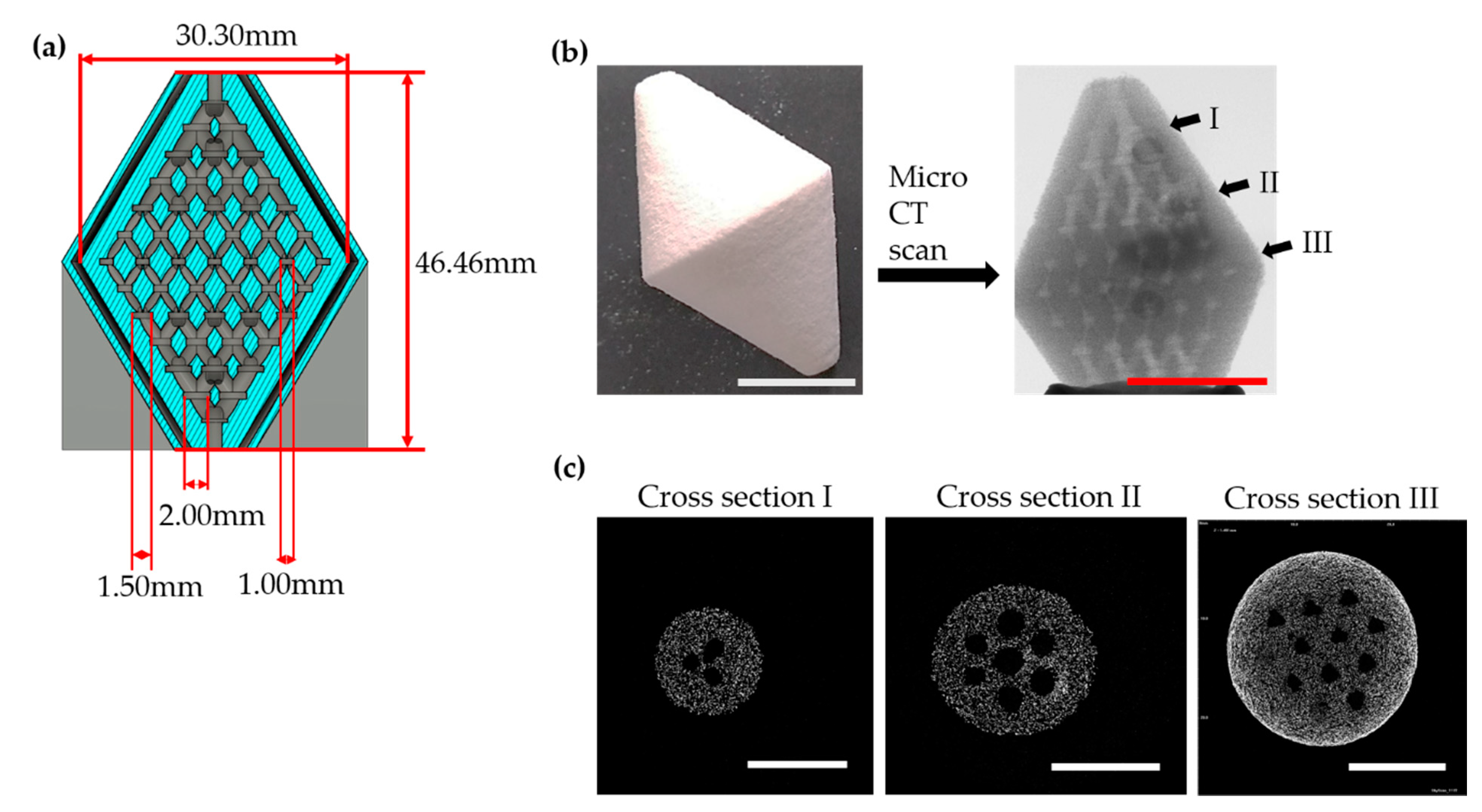
2.1. Design of Scaffold

A perfusable 3-D interconnected scaffold was designed as previously reported by our group [12]. The CAD model was designed in such a way to ensure continuity from inlet to outlet using AutoCAD software. It had 2 truncated cones joined at the center with a maximum diameter of 30.30 mm. The outlets at 2 opposite ends were connected through 3-D branched flow channels. The diameter of flow channels inside the device could be sectioned into 3 different layers, and each layer had varied inner diameters of flow channels as follows: 2 mm, 1.5 mm, and 1 mm, respectively, starting from outlet toward the center. The height of the device was 46.46 mm and the total volume was 11.02 cm3.

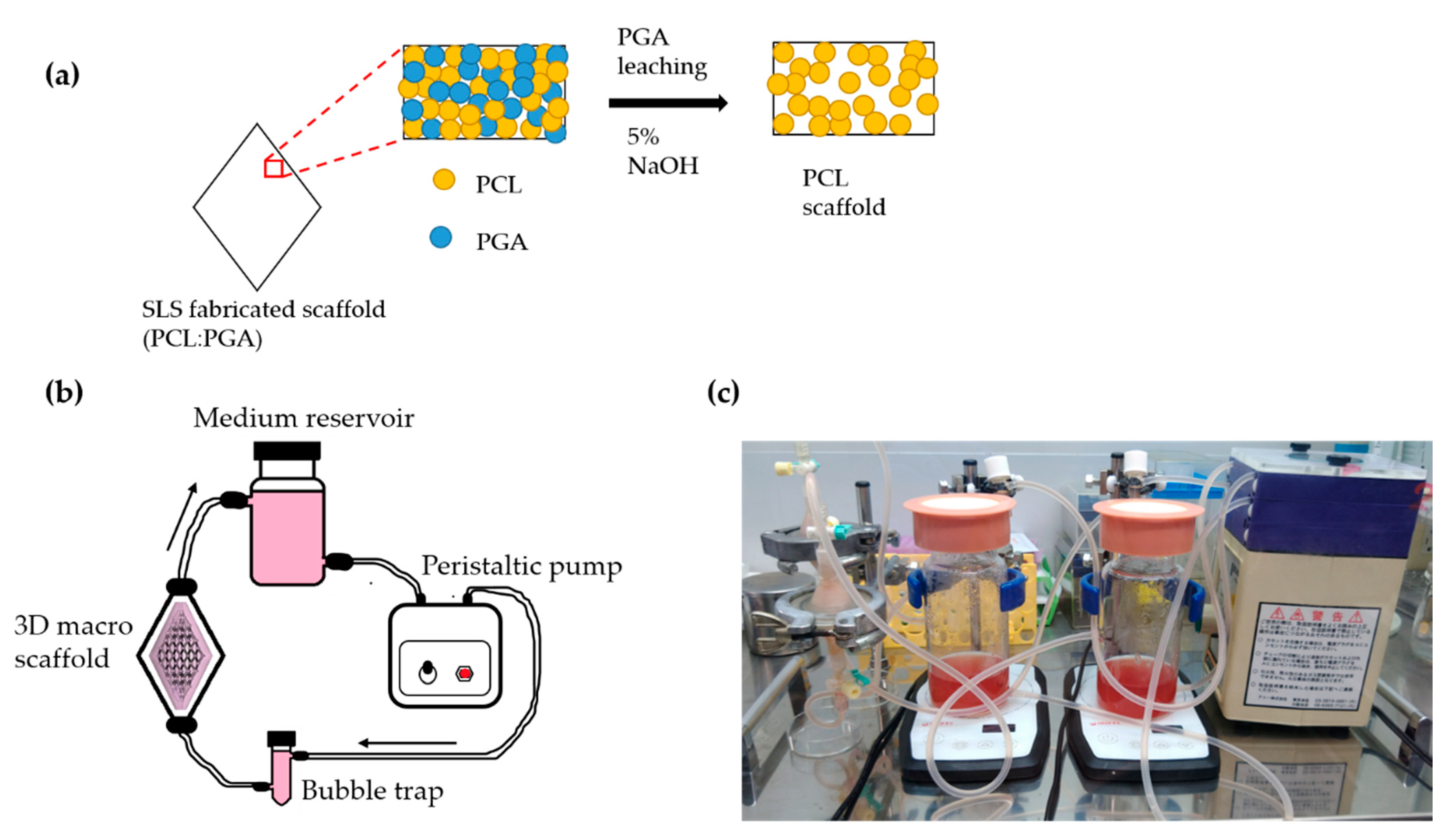
2.2. Fabrication of Scaffold Using Selective Laser Sintering

Polycaprolactone (PCL, Molecular weight 50,000 Da, CAPA® 6500, Perstorp, Japan) particles with average size of 51 µm and polyglycolic acid (PGA, Molecular weight 1.8 × 10⁵ M.W, B35, Kureha, Japan) particles with average size of 112 µm were used as raw materials. PCL (particle size: 0–100 µm) and PGA (particle size 100–150 µm) powders were collected by sieving and were combined manually in 1:2 (PCL:PGA) ratio prior to sintering. PGA was used as sacrificial filler to enhance the porous nature of scaffold after the removal of PGA from the fabricated 3-D scaffold.
The G-code was prepared with the embedded slicing software provided by the manufacturer of the printing machine (Semplice, Aspect Inc., Tokyo, Japan). The SLS printing machine was equipped with a gaussian-type CO2 laser sintering machine. The platform of the machine was preheated below the recrystallisation temperature to make each layer solid after sintering. The parameters for sintering are shown in Table 1. After sintering was completed, the scaffolds were retrieved from the build chamber and subjected to treatment with 5% NaOH for 24 h in rotational shaking at the speed of 90 rpm in 37 °C to dissolve the PGA particles from the scaffold. The scaffold was rinsed carefully with 1X phosphate buffered saline 3 times to wash out the NaOH.

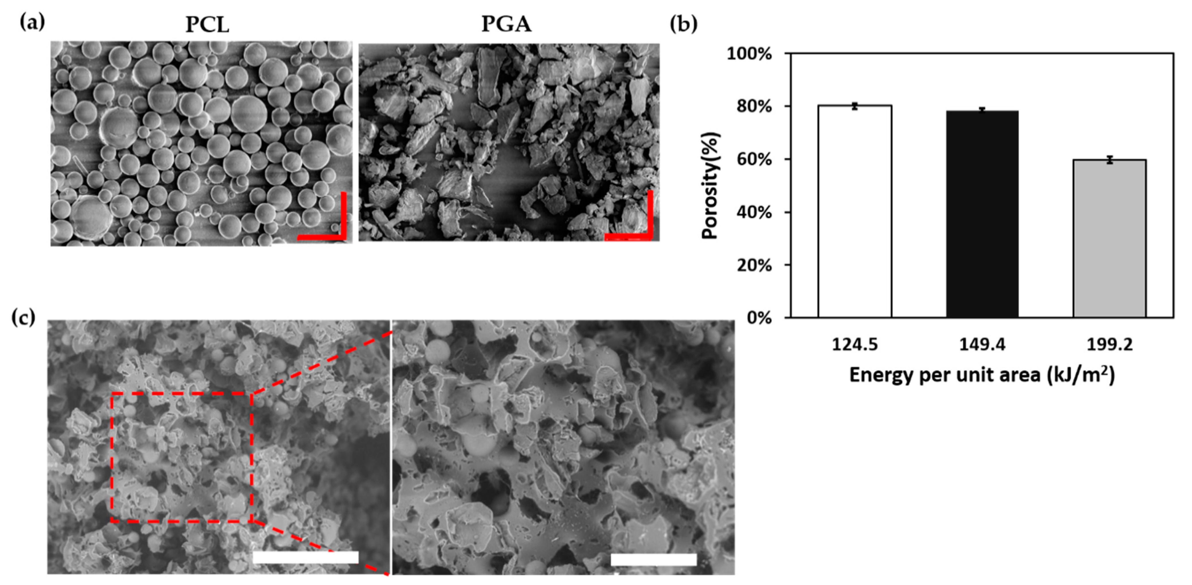
2.3. Porosity Measurement and Morphology of Scaffold

The density of the scaffold was determined as follows:
D = m / v
where D is the density of scaffold, m is mass, and v is volume.
Furthermore, the % of porosity of the scaffold p can be measured as follows:
%   of   Porosity   ( p ) = ( 1 D D 0 ) 100
where D is the density of scaffold and D 0   is the density of the material (PCL).
The inner channels of the fabricated scaffold were evaluated by micro-computed tomography (Micro X-ray System SMX-225CT, Shimadzu, Japan). Additionally, the structural integrity of the scaffold was screened using scanning electron microscopy (SEM) (TM3030, Japan). Then, 1 mm-thick slices from the perfusable device were subjected to chemical drying in ethanol treatment for 5 min each time in 25%, 50%, 70%, and 95% EtOH, respectively, and left to dry at room temperature for 3 h. The dried samples were placed on the carbon tape and imaged in 15 kV.

2.4. Perfusion Culture Setup for 3-D Scaffold

Human hepatoma HepG2 (Japanese cancer research bank, JCRB) cells were maintained in low-glucose Dulbecco’s modified minimum essential medium (DMEM) supplemented with 10% fetal bovine serum (FBS), 1% non-essential amino acids (NEAA), 4 mM hydroxyethyl piperazine-N’ -2-ethanesulfonic acid (HEPES), and 1% antibiotic-antimycotic. Confluent cells were washed with PBS and retrieved using Trypsin/EDTA. The cells were resuspended in DMEM culture medium for subsequent use in the experiment.
Human umbilical vein endothelial cell HUVEC (Catalog #: C2517A, Lonza) cells were maintained in Endothelial cell basal medium supplemented with endothelial growth factors (EBMTM-2 Basal medium and EGMTM-2 SingleQuotesTM supplements, Lonza, Switzerland) and 1% antibiotic-antimycotic. Prior to seeding the cells into the scaffold, confluent cells were washed with PBS, followed by Trypsin/EDTA treatment, and the retrieved cells were resuspended in EBM-2 medium.
The scaffolds were rinsed carefully to remove remnants of NaOH and PGA particles, followed by collagen surface treatment on PCL. Collagen (0.01% collagen type I, Nitta Gelatin, Japan) was adsorbed onto the surface overnight at 4 °C. After collagen treatment, the scaffold was rinsed thoroughly with 1X PBS and allowed to soak in culture medium for 2 h prior to cell seeding.
Hep G2 cell suspension of 1 × 10⁷ in 10 mL culture medium was injected into the scaffold by two 10 mL syringes inserted in the inlet and outlet, which were depressed and released at a slow speed within 3 min. To ensure the homogeneous distribution of cells inside the scaffold, the scaffold was kept in 3 different directions (0°, 180°, and 240°) and held each time for 5 min. The perfusion was gently started at 1 mL/min. After 2 h, the flow rate of the culture medium was gradually increased to 5 mL/min. The culture medium was replaced on day 1, and thereafter, every 2 days until day 10. The total volume of the culture medium was kept constant to 100 mL in the medium reservoir. The configuration of perfusion culture system is illustrated in Figure 1b. The perfusion culture system comprised of a peristaltic pump, bubble trap, PCL-based scaffold, and medium reservoir.
For the co-culture system, the human umbilical endothelial cells (HUVECs) were introduced into the scaffold in a similar manner as mentioned above, with a cell suspension of 0.5 × 10⁷ in a 10 mL culture medium after Hep G2 were grown at day 2 in the scaffold to allow the coverage of endothelial cell layer growing on the grown Hep G2 on the scaffold. The co-culture medium consisted of DMEM and EBM-2 and was supplemented with EGM-2 mixture (1 DMEM: 1 EBM-2+EGM-2), 10% fetal bovine serum (FBS), 1% non-essential amino acids (NEAA), 4 mM hydroxyethyl piperazine-N’ -2-ethanesulfonic acid (HEPES), and 1% antibiotic-antimycotic. Scaffold without cells were considered as a control group. All the cultures were performed at 37 °C in a CO2 incubator.

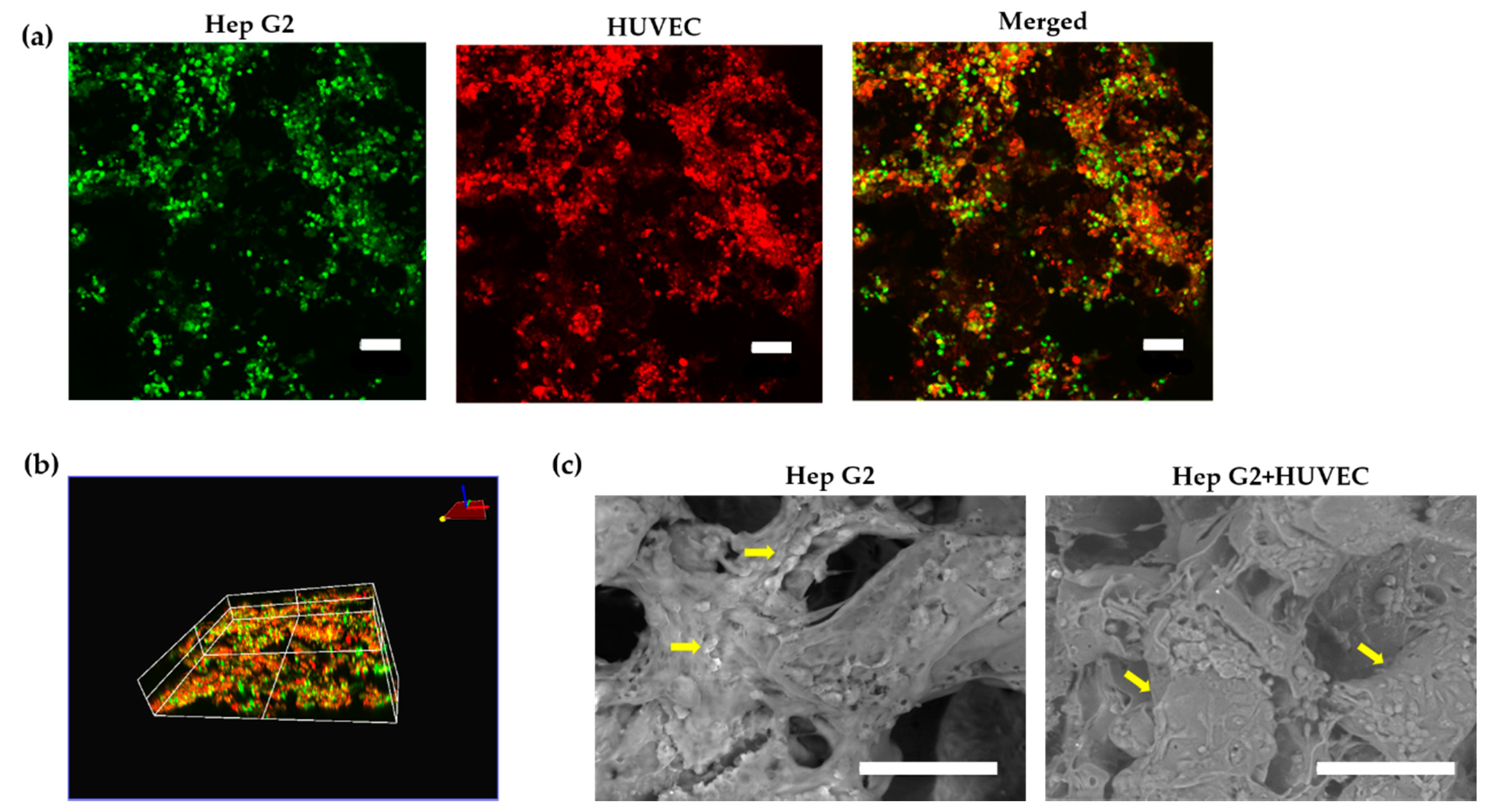
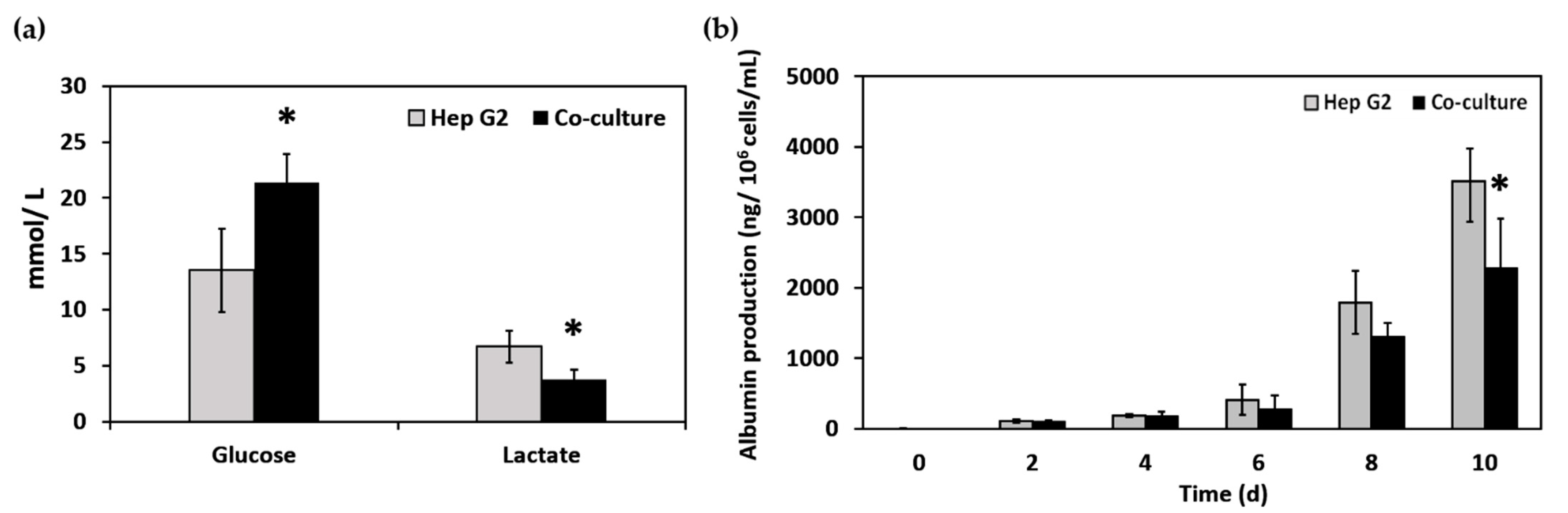
2.5. Cell Localization and Cellular Metabolism

The cell distribution and localization within the scaffold was tracked using cell tracker staining of the live cells until day 10. Hep G2 and HUVEC live cells were stained with green CMFDA dye (CellTrackerTM Invitrogen, C2925) and orange CMRA dye (CellTrackerTM Invitrogen, C34551), respectively, and seeded into the scaffold. The fluorescent images of live cells were observed under confocal microscope (FV3000, Olympus, Tokyo, Japan) after day 10 of culture under perfusion. The excitation/emission wavelength of green CMFDA was 492/517 nm and orange CMRA dye was 548/576 nm. Images were processed using the cellSens dimension software suite (Olympus, Tokyo, Japan). In parallel, the cell attachment was also observed under SEM. The samples were prepared by fixing with 4% PFA followed by series of dehydration in different concentration ethanol, namely 25%, 50%, 70%, and 95%, and drying at room temperature for 3 h prior to observation under SEM (TM3030, Hitachi, Tokyo, Japan).
Additionally, the cellular metabolism of glucose consumption was analyzed using a BD-7D bioanalyzer (Oji Scientific, Tokyo, Japan). Furthermore, albumin production by Hep G2 were also assessed from the collected culture supernatant using sandwich-type enzyme linked immune-sorbent assay (ELISA) with goat antihuman albumin and HRP-conjugated goat antihuman albumin (Bethyl Laboratories, Montgomery, USA). The measurement was carried out using microplate reader (Wallac ArvoTM 5X) at 490/620 nm wavelength.

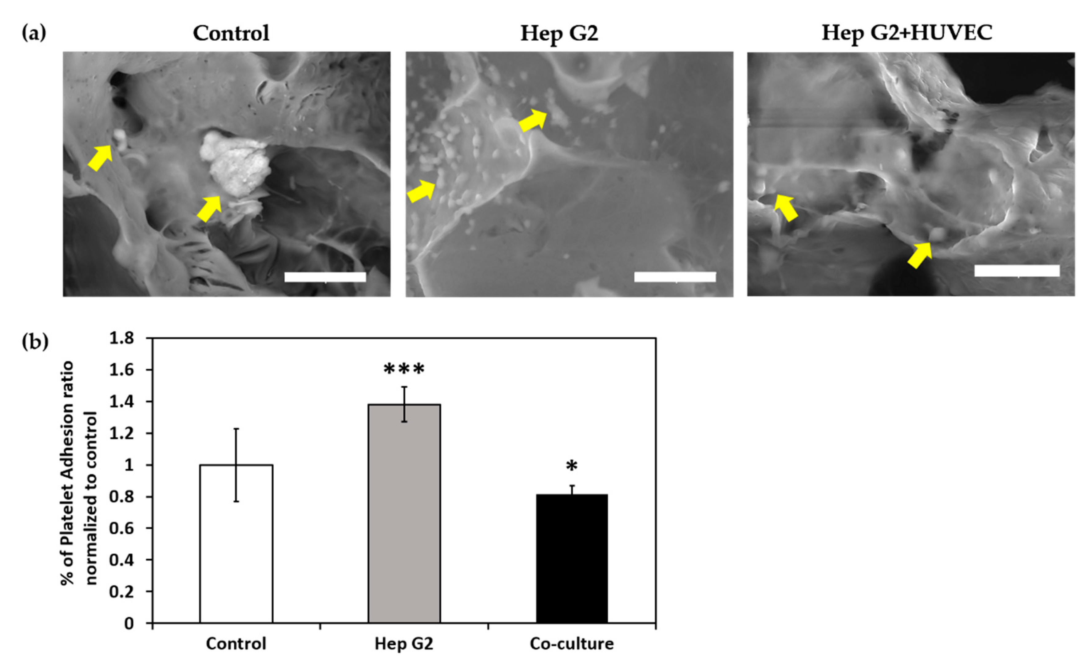
2.6. Platelet Deposition on Scaffold

Porcine whole blood was collected from Tokyo Shibaura with 3.24% sodium citrate and 10% by volume anticoagulant in 50 mL tubes. The platelet separation from whole blood involved a 3-step process of centrifugation. First, plasma was separated from the whole blood by centrifugation at 1000 rpm for 20 min. Subsequently, the upper layer, i.e., the plasma collected, was subjected to a second round of centrifugation at 1000 rpm for 20 min, and the supernatant was platelet rich plasma (PRP). Finally, the PRP was centrifuged at 2500 rpm for 10 min. The pellets consisted of platelets, and the supernatant was platelet-poor plasma (PPP). To evaluate the platelet deposition and adhesion of scaffold, the total number of platelets adjusted by mixing PPP and PRP to be 4.5 × 10⁹ platelet/100 mL. Then, PPP was incubated with the scaffold under perfusion for 2 h at a flow rate of 2 mL/min and 37 °C. After 2 h of incubation, the total number of platelets was counted from the retrieved platelet suspension. The percentage of platelet adhesion ratio (% of PAR) on the scaffold covered with Hep G2 and the co-culture model was calculated using the equation below:
%   of   Platelet   adhesion   ratio   = ( P 0 Ps ) / ( P 0 Pc )  
where P0 is the total number of platelets deposited, Ps is the total number platelet retrieved from the sample, and Pc is the total number of platelets retrieved from the control after 2 h of incubation.
In another parallel study, the platelet deposition and aggregation on the samples were observed under SEM (TM3030, Hitachi, Tokyo, Japan). The samples with platelet deposited were fixed in 4% Paraformaldehyde (PFA) overnight at 4 °C. Cross sections of 1 mm-thick slices were dehydrated in a series of ethanol solution with concentrations of 25%, 50%, 75%, and 95% (v/v) for 10 min each. The samples were further dried at room temperature for 3 h before observation under SEM at 15 kV.

2.7. Statistical Analysis

The results were expressed as mean with standard deviation (SD). All the quantitative values were performed at least 3 times. The number of independent experiments were repeated 3 times. Student’s t-test was used to assess the Hep G2 culture condition and co-culture condition of the scaffolds, with p < 0.05 considered significant.

3. Results

3.1. Fabrication of Scaffold

The three-dimensional scaffold was printed by translating the CAD model as depicted in Figure 2a using the SLS printer. The truncated shape of the macroporous scaffold with interconnected branches in multilayers was to accommodate larger volume of scaffold in 3-D space, which can be physiologically significant. Therefore, the macroporous scaffold design had an inlet and outlet with interconnected branches for the uniform distribution of the culture medium. Toward the center of the macroporous scaffold, from one of the openings, the diameter of the interconnected channel was subdivided into three layers of 2 mm, 1.5 mm, and 1 mm, designated as region I, II, and III, respectively, in Figure 1b. Furthermore, the detailed diameter was screened using micro-CT scanning of cross sections of region I, II, and III in Figure 2c.

3.2. Porosity Measurement and Morphology of Scaffold

To attain maximum porosity within the 3-D space of the scaffold, PGA microparticles with average size of 112 µm, as shown in Figure 2a, were used as sacrificial material, which acted as porogens in the PCL matrix with average size of 51 µm. Both the particles were mixed in the ratio of 1:2 (PCL:PGA) and sintered at an energy density of 149.4 kJ/m2. The percentage of porosity was measured as 78%. It is worth mentioning that the porosity of the scaffold was governed by changing the energy density of the sintering machine. These parameters were taken into consideration for all cell culture experiments.
Figure 3b indicates that when the energy density was increased, the porosity of the scaffold decreased. A porosity of 80% could also be possible by applying an energy density of 124.5 kJ/m2. However, after removal of the PGA particles, the 3-D construct lost the structural stability and breakdown of the material, which led to leakage of the culture medium when subjected to perfusion after 30 min. When higher energy density was used to sinter PCL and PGA, only 60% porosity was achieved, which would not be feasible for mass transport of culture medium and also cell distribution in the scaffold. The microarchitecture of the scaffold was observed under SEM, as demonstrated in Figure 3c after the leaching of PGA particles in the presence of 5% NaOH treatment post fabrication. The leached spaces within the PCL framework could provide empty voids, which would allow uniform distribution of culture medium throughout the scaffold.

3.3. Cell Localization and Cellular Metabolism

The cell localization and immobilization of Hep G2 and HUVECs cultured on the scaffold was observed by confocal microscopy after 10 days of the culture system, as shown in Figure 4a,b. The z-stack-compiled volume view demonstrates the coverage of both the Hep G2 and HUVECs layer on the scaffold, as shown in Figure 4b. The full coverage of endothelial cells or endothelization is important to study blood compatibility. However, the limitation of macroporous structure of the scaffold was the visualization of the full coverage of the endothelial cells throughout the scaffold for live imaging. Hep G2 and HUVECs attachment on the scaffold could also be observed under SEM, as demonstrated in the Figure 4c. Endothelial cells plays a major role in the regulation of coagulation [28], mainly mediating the interaction between blood and tissues. Therefore, the coverage of endothelial cell lining can mitigate the formation of thrombus when the scaffold comes in contact with blood, thereby improving the antithrombotic capacity of the biomaterial.
The glucose uptake and lactate production by Hep G2 and the co-culture were compared and are shown in Figure 5a. We observed that at day 10, the consumption of glucose of the co-culture system was significantly higher than the pure Hep G2 culture condition. On the other hand, the lactate production of the co-culture system was significantly lower than the pure Hep G2 culture condition. The metabolism of glucose uptake and lactate production indicate the overall environment of the culture system. Accumulation of high lactate can create an acidic environment and may lead to the induction of oxidative stress, thereby affecting the health of the cells. Therefore, it is vital to maintain the nonacidic environment for healthy cell growth.
The albumin production was monitored every 2 days until day 10. The highest albumin production was observed at day 10 for the Hep G2-cultured scaffold, whereas there was significant reduction in the case of the co-culture condition from Figure 5b. The lower production of albumin may be due Hep G2, as well as HUVECs, striving for glucose. Therefore, further optimization is needed to resolve the effect of endothelial lining on Hep G2 in the macro scaffold under the perfusion culture system.

3.4. Platelet Deposition and Adhesion

Qualitative analysis of platelet deposition on the scaffold was visualized using SEM imaging, as shown in Figure 6a. The platelets deposition and aggregation on Hep G2-covered scaffold from the SEM images revealed large number of depositions attached to the surface when compared to the co-culture-coated scaffold. Platelets deposited on the surface could be identified as shown by yellow-marked arrows in Figure 6a.
The quantitative analysis of platelet adhesion was estimated by the measurement of percentage of platelet adhesion ratio (% of PAR). The platelet adhesion ratio of the Hep G2-covered scaffold was 1.38-times higher than the control (no cell). Upon coming into contact with plasma, Hep G2 showed a greater adherence to platelets and aggregation. However, significant difference (p < 0.05) in % of PAR was observed in the case of the co-culture (Hep G2+ HUVEC) model of endothelized Hep G2 scaffold when compared to the control, as shown in Figure 6b. The result demonstrated that the antiplatelet adhesion of the HUVECS co-cultured with Hep G2 was higher than only Hep G2 cultured on the scaffold. The antiplatelet adhesion behavior of the co-culture model showed that the HUVECs layer served as barrier between the liver cells and platelets. If the platelets could interact with exposed Hep G2 on the scaffold, the interaction between them would become stronger. The co-culture of Hep G2 with HUVECs indicated better antiplatelet adhesion with the channel system with the current design, mimicking the flow system. The improved antiplatelet adhesion property of the endothelized Hep G2-cultured scaffold could be related to the endothelial cell glycocalyx layer reported by Chen et al. [26], thereby rendering hemocompatibility.

4. Discussion

This work demonstrates that large-scale 3-D scaffold can be fabricated using the SLS printing method. The limitation of struts thickness growth due to heat conduction of particles was overcome using PGA microparticles over the conventional method based on NaCl salt particles. The resultant scaffolds were characterized by a micro-CT scan and SEM imaging. The PGA porogen leaching gave rise to 78% porosity. The porosity of the scaffold is essential for the distribution of the culture medium or blood plasma to ensure mass transfer and diffusion. [12]. The process of leaching out PGA microparticles by dissolving in NaOH is an easy process and does not disrupt the 3-D branched flow channels.
The fabricated PCL scaffolds were seeded with Hep G2 for the illustration of metabolic functions. The albumin production, glucose metabolism, and lactate production remained active under perfusion culture system for 10 days. However, when the HUVECs were allowed to endothelize the Hep G2-covered scaffold, the albumin production was reduced. This limitation needs optimization to circumvent the functioning of Hep G2 in the co-culture system under a flow culture environment in a macro scaffold. The layer of endothelial cells grown on Hep G2 was observed by live imaging. The confluency of HUVECs on Hep G2 is crucial for imparting hemocompatibility.
Hemocompatibility is an important issue when it comes to the development of transplantable internal organs. Determining hemocompatibility of the scaffold is vital to rule out possible blood trauma that such material may cause [29]. The confluency of EC lining on Hep G2 plays an important role in the overall assessment of hemocompatibility [26,30]. Complete endothelization of the engineered scaffold is essential for the long-term survival of functional tissue after implantation to avoid thrombosis and fibrosis [31]. The current prototype enables plasma perfusion within the flow channels. We screened the antiplatelet adhesion behavior of the scaffold, which was covered with Hep G2 and compared with endothelized Hep G2. The results revealed that there were significant differences between Hep G2 and endothelized Hep G2-covered scaffolds. The adherence of platelets on the Hep G2 scaffolds was much higher when compared with the endothelized Hep G2 scaffolds when perfused with platelets rich plasma. The reduction in platelet adherence is an indicator for the functional efficacy of HUVEC co-cultured with the Hep G2 scaffold. The presence of HUVECs significantly reduced the thrombogenicity of the scaffold. However, a key challenge of hemocompatibility with endothelized scaffolds holds potential in future application for tissue engineering in the reconstitution of implantable liver tissue.

Author Contributions

Methodology, K.F., M.S., M.D. and K.I.; Conceptualization, T.N. and Y.S.; investigation, M.L. and R.R.K.; Supervision, T.N., Y.S. and M.N. (Masaki Nishikawa); Methodology, M.N. (Mitsuru Nagayama); writing and supervision, M.N. (Masaki Nishikawa); manuscript writing and final approval of manuscript, all authors. All authors have read and agreed to the published version of the manuscript.

Funding

This research did not receive any specific grant from funding agencies in the public, commercial or not for profit sectors.

Institutional Review Board Statement

Not applicable.

Informed Consent Statement

Not applicable.

Acknowledgments

The authors wish to thank Hirokazu Ikeda for designing consultation.

Conflicts of Interest

The authors declare no conflict of interest.

References

  1. Dhariawala, B.; Hunt, E.; Thomas, B. Rapid Prototyping of Tissue-Engineering Constructs, Using Photopolymerizable Hydrogels and Stereolithography. Tissue Eng. 2004, 10, 1316–1322. [Google Scholar] [CrossRef]
  2. Sakai, Y.; Otsuka, M.; Hanada, S.; Nishiyama, Y.; Konishi, Y.; Yamashita, A. A novel poly-l-lactic acid scaffold that possesses a macroporous structure and a branching/joining three-dimensional flow channel network: Its fabrication and application to perfusion culture of human hepatoma Hep G2 cells. Mater. Sci. Eng. C 2004, 24, 379–386. [Google Scholar] [CrossRef]
  3. Kaihara, S.; Borenstein, J.; Koka, R.; Lalan, S.; Cunningham, B.; Vacanti, J. 7-Silicon Micromachining to Tissue Engineer Branched Vascular Channels for Liver Fabrication. Tissue Eng. 2000, 6, 105–117. [Google Scholar] [CrossRef] [Green Version]
  4. Lewis, P.L.; Shah, R.N. 3D Printing for Liver Tissue Engineering: Current Approaches and Future 3D Printing for Liver Tissue Engineering: Current Approaches and Future Challenges. Curr. Transplant. Rep. 2016, 3, 100–108. [Google Scholar] [CrossRef]
  5. Williams, M.J.; Adewunmi, A.; Schek, R.; Flanagan, C.; Krebsbach, P.; Feinberg, S.; Hollister, S.; Das, S. Bone tissue engineering using polycaorolactone scaffolds fabricated via selective laser sintering. Biomaterials 2005, 26, 4817–4827. [Google Scholar] [CrossRef]
  6. Chua, C.K.; Leong, K.F.; Wang, Y. Fabrication of customised scaffolds using computer-aided design and rapid prototyping techniques. Rapid Prototyp. J. 2005, 4, 249–259. [Google Scholar] [CrossRef]
  7. Leong, K.F.; Chua, C.K.; Sudarmadji, N.; Yeong, W.Y. Review article Engineering functionally graded tissue engineering scaffolds. J. Mech. Behav. Biomed. Mater. I 2008, 1, 140–152. [Google Scholar] [CrossRef]
  8. Cheah, C.M.; Chua, C.K.; Leong, K.F.; Cheong, C.H.; Naing, M.W. Automatic Algorithm for Generating Complex Polyhedral. Tissue Eng. 2004, 10, 595–610. [Google Scholar] [CrossRef] [PubMed]
  9. Hollister, B.S.J. Scaffold Design and Manufacturing: From Concept to Clinic. Adv. Mater. 2009, 21, 3330–3342. [Google Scholar] [CrossRef] [PubMed]
  10. Duan, B.; Cheung, W.L.; Wang, M. Optimized fabrication of Ca – P / PHBV nanocomposite scaffolds via selective laser sintering for bone tissue engineering. Biofabrication 2011, 3, 1–13. [Google Scholar] [CrossRef] [PubMed]
  11. Lee, K.; Wang, S.; Yaszemski, M.J.; Lu, L. Enhanced cell ingrowth and proliferation through three dimensional nanocomposite scaffolds with controlled pore structures. Biomacromolecules 2010, 11, 682–689. [Google Scholar] [CrossRef] [Green Version]
  12. Huang, H.; Oizumi, S.; Kojima, N.; Niino, T.; Sakai, Y. Avidin-biotin binding-based cell seeding and perfusion culture of liver-derived cells in a porous scaffold with a three-dimensional interconnected flow-channel network. Biomaterials 2007, 28, 3815–3823. [Google Scholar] [CrossRef] [PubMed]
  13. Davis, M.W.; Vacant, J.P. Toward development of an implantable tissue engineered liver. Biomaterials 1996, 17, 365–372. [Google Scholar] [CrossRef]
  14. Hammond, J.S.; Beckingham, I.J.; Shakesheff, K.M. Scaffolds for liver tissue engineering. Expert Rev. Med. Devices 2006, 3, 21–27. [Google Scholar] [CrossRef] [PubMed]
  15. Lohfeld, S.; Tyndyk, M.A.; Cahill, S.; Flaherty, N.; Barron, V.; McHugh, P.E. A method to fabricate small features on scaffolds for tissue engineering via selective laser sintering. J. Biomed. Sci. Eng. 2010, 3, 138–147. [Google Scholar] [CrossRef]
  16. Kim, S.S.; Utsunomiya, H.; Koski, J.A.; Wu, B.M.; Cima, M.J.; Sohn, J.; Mukai, K.; Griffith, L.G.; Vacanti, J.P. Survival and Function of Hepatocytes on a Novel Three-Dimensional Synthetic Biodegradable Polymer Scaffold With an Intrinsic Network of Channels. Ann. Surg. 1998, 228, 8–13. [Google Scholar] [CrossRef] [PubMed]
  17. Ji, J.; Pang, Y.; Sutoko, S.; Horimoto, Y.; Sun, W.; Niino, T.; Sakai, Y. Design, Fabrication, and Evaluation of Polyglycolic Acid Modules with Canals as Tissue Elements in Cellular—Assembly Technology. Appl. Sci. 2020, 10, 3748. [Google Scholar] [CrossRef]
  18. Griffith, L.G.; Wells, A.; Stolz, D.B. Engineering liver. Hepatology 2014, 60, 1426–1434. [Google Scholar] [CrossRef] [PubMed] [Green Version]
  19. Page, C.O.F.; Griffith, L.G.; Naughton, G. Tissue Engineering—Current Challenges and Expanding Opportunities. Science 2002, 295, 1009–1014. [Google Scholar]
  20. Michael, E.; Schaubel, D.; Cai, S.; Guidinger, M.; Merion, R. Portal vein thrombosis and liver transplant survival benefit. Liver Transpl. 2010, 16, 999–1005. [Google Scholar] [CrossRef]
  21. Braune, S.; Latour, R.A.; Reinthaler, M.; Landmesser, U.; Lendlein, A.; Jung, F. In Vitro Thrombogenicity Testing of Biomaterials. Adv. Healthc. Mater. 2019, 8. [Google Scholar] [CrossRef] [PubMed] [Green Version]
  22. Reinthaler, M.; Braune, S.; Lendlein, A.; Landmesser, U.; Jung, F. Platelets and coronary artery disease: Interactions with the blood vessel wall and cardiovascular devices. Biointerphases 2016, 11, 029702. [Google Scholar] [CrossRef]
  23. Braune, S.; Groß, M.; Walter, M.; Zhou, S.; Dietze, S.; Rutschow, S.; Lendlein, A.; Tschöpe, C.; Jung, F. Adhesion and activation of platelets from subjects with coronary artery disease and apparently healthy individuals on biomaterials. J. Biomed. Mater. Res. Part B Appl. Biomater. 2016, 104, 210–217. [Google Scholar] [CrossRef]
  24. Denadai, R.; Teixeira, F.V.; Saad-Hossne, R. Management of psoriatic lesions associated with anti-TNF therapy in patients with IBD. Nat. Rev. Gastroenterol. Hepatol. 2012, 9, 744. [Google Scholar] [CrossRef] [Green Version]
  25. Weber, M.; Steinle, H.; Golombek, S.; Hann, L.; Schlensak, C.; Wendel, H.P.; Avci-Adali, M. Blood-Contacting Biomaterials: In Vitro Evaluation of the Hemocompatibility. Front. Bioeng. Biotechnol. 2018, 6, 99. [Google Scholar] [CrossRef]
  26. Chen, Y.M.; Tanaka, M.; Gong, J.P.; Yasuda, K.; Yamamoto, S.; Shimomura, M.; Osada, Y. Platelet adhesion to human umbilical vein endothelial cells cultured on anionic hydrogel scaffolds. Biomaterials 2007, 28, 1752–1760. [Google Scholar] [CrossRef]
  27. Liu, P.; Tian, B.; Yang, L.; Zheng, X.; Zhang, X.; Li, J.; Liu, X. Hemocompatibility improvement of decellularized spleen matrix for constructing transplantable bioartificial liver Hemocompatibility improvement of decellularized spleen matrix for constructing transplantable bioarti fi cial liver. Biomed. Mater. 2019, 14, 1–10. [Google Scholar] [CrossRef] [PubMed]
  28. Van Hinsbergh, V.W.M. Endothelium—Role in regulation of coagulation and inflammation. Semin. Immunopathol. 2012, 34, 93–106. [Google Scholar] [CrossRef] [PubMed] [Green Version]
  29. Jesus, C.; Perera, C.; Guadalupe, M.; Baas, C.; Abigail, G.; Lara, A.; Isaai, S.; Borges, R.; Leticia, A.; Guzmán, R.; et al. Characterization and hemocompatibility assessment of porous composite scaffolds with a biomimetic human clavicle macrostructure. Health Technol. 2020, 10, 423–428. [Google Scholar]
  30. Mcguigan, A.P.; Sefton, M. V Vascularized organoid engineered by modular assembly enables blood perfusion. Proc. Natl. Acad. Sci. USA 2006, 103, 11461–11466. [Google Scholar] [CrossRef] [PubMed] [Green Version]
  31. Sakai, Y.; Huang, H.; Hanada, S.; Niino, T. Possessing a clinically significant mass. Biochem. Eng. J. 2009, 1–14. [Google Scholar] [CrossRef]
Figure 1. (a) Schematic illustration of polyglycolic acid (PGA) leaching using 5% NaOH to produce porous polycaprolactone (PCL) macro scaffold postprocessing of SLS printing; (b) schematic illustration of perfusion culture setup consisting of peristaltic pump, bubble trap, scaffold, and medium reservoir; (c) configuration of perfusion culture system.
Applsci 11 02473 g001
Figure 2. (a) Computer aided design (CAD) model and dimension of the 3-D scaffold; (b) fabricated three-dimensional scaffolds after selective laser sintering (SLS) printing and micro-CT scan. The scale bars are 10 mm. (i) Slices from different layers of the scaffold with internal diameters of the channel of 2 mm (ii), 1.5 mm (iii), and 1 mm (iv); (c) cross section of the internal diameter of interconnected channel (scale bar 10 mm, magnification 5×. The slices of cross section I (approximately channel diameter 2 mm), cross section II (approximately channel diameter 1.5 mm), and cross section III (approximately channel diameter 1 mm) was sliced from region I, II, and III as depicted in (b).
Applsci 11 02473 g002
Figure 3. (a) Morphology of the PCL and PGA microparticle under scanning electron microscopy (SEM) (scale bar 100 µm, magnification 500×); (b) the % of porosity of the 3-D construct versus energy density. Each column represents mean ± SD with n = 3 independent experiments; (c) morphology of the macroporous scaffold after leaching out of PGA microparticle under SEM, showing the porous network (scale bar 500 µm, magnification 100× and 200 µm, magnification 200×).
Applsci 11 02473 g003
Figure 4. (a) Live imaging of Hep G2 and human umbilical vein endothelial cells (HUVEC) after 10 days of perfusion culture (scale bars 100 µm, magnification 4×); (b) volume z-stacked view of the Hep G2 and HUVEC cultured on the scaffold; (c) SEM images of Hep G2-covered scaffold and co-culture of Hep G2 and HUVEC at day 10. The yellow arrows show the morphology of Hep G2 and HUVEC grown on the scaffold (scale bar 100 µm, magnification 200×).
Applsci 11 02473 g004
Figure 5. (a) Glucose consumption and lactate production of pure culture Hep G2 and co-culture Hep G2/HUVEC under perfusion culture system at day 10; (b) albumin production between Hep G2 and co-culture Hep G2/HUVECs showed significant different with p < 0.05 indicated by * at day 10. Each column represents the mean ± SD (n = 3 independent experiments), * p < 0.05.
Applsci 11 02473 g005
Figure 6. Hemocompatibility assessment: (a) SEM images of scaffold deposited with platelets on the control (no cell), Hep G2-covered scaffold, and co-culture (Hep G2 +HUVEC) scaffold. Platelet deposition and aggregation are shown by yellow arrows (scale bar is 20 µm, magnification 1000×); (b) The % of platelet adhesion ratio (% of PAR) of the Hep G2-covered scaffold and co-cultured scaffold normalized to the control. Each column represents mean ± SD with n = 3 independent experiments, * p < 0.05, *** p < 0.005 versus control.
Applsci 11 02473 g006
Table 1. Specifications of CO2 gaussian laser sintering machine.
ParameterSettings
MaterialPCL: PGA (1:2) by volume
Spot diameter170 µm
Power9 W
Pre heat temperature40 °C
Scan speed1.5 m/s
Scan line pitch40 µm
Energy per unit area49 kJ/m2
Layer thickness200 µm
Publisher’s Note: MDPI stays neutral with regard to jurisdictional claims in published maps and institutional affiliations.

