
Energy Consumption Structure and Its Improvement of Low-Lifting Capacity Scissor Lift


Institute of Machine Tools and Production Engineering, Lodz University of Technology, Stefanowskiego 1/15 Street, 90-924 Lodz, Poland
*
Author to whom correspondence should be addressed.
Energies 2021, 14(5), 1366; https://doi.org/10.3390/en14051366
Submission received: 26 January 2021
/
Revised: 21 February 2021
/
Accepted: 26 February 2021
/
Published: 2 March 2021
Abstract
:The article presents the experimental investigation of low-lifting capacity hydraulic scissor lift energy consumption. The analysis is based on experimental tests of two individual drives of the scissor lift: the conventional one and the variable-speed electro-hydraulic one. The investigation focuses on the study of the total energy consumption for lifting and lowering the scissor lift with different masses of transported cargo and also power consumptions of each element supplying these systems. Particular attention was paid to the significant impact of power supply on each control component as the main factor of reduction in the energetic efficiency of the low-lifting capacity scissor lift. A comparison of both drives indicated that the mass of transported cargo has a significant influence on the choice of the drive used. Results of the research show that significant energetic savings are obtained, as the modernized propulsion system consumes 67% energy of the standard one. A decrease in the percentage of energy losses with the increase in the mass handled led to the conclusion that the enhancement of propulsion systems in scissor lifts should be especially considered in machines carrying big loads.
1. Introduction
Dynamic development of various industry branches is characterized by the increasing use of machines and devices with much more advanced technology. Thanks to them, work becomes less strenuous, more efficient, and allows us to achieve set goals faster. The above brings many challenges in energy optimization of working machines, widely used in production, assembly, transport, and reloading processes in industrial facilities. Thus, the issues related to energy efficiency are areas of interest for an increasing number of machine designers and users. Much attention is currently being paid to ecological and also economic issues related to energy saving, energy efficiency [1], and lower fuel consumption. Natural resources are decreasing, so there is a need to find new, much more energy-efficient, solutions for drive systems [2].
The problem of energy saving does not take into account low-lifting capacity devices. The studies mainly concern most heavy working machines, e.g., heavy earth-moving machinery (HEMM). It is an area of interest among many researchers [3,4]. When lifting the excavator boom, a large amount of potential energy is generated, which is dissipated as heat through valves [5,6]. This phenomenon leads to lower energy efficiency. The energy can be recovered, e.g., while lowering the boom. However, it is necessary to use appropriate systems and control methods. These systems and methods are similar to heavy machines and also light-duty machines such as forklifts and all kinds of hydraulic lifts.
Currently, working machines use hybrid drives engaging energy regeneration systems. The systems are based on batteries, flywheels, or supercapacitors [7,8]. In [1], the issue of energy recovery in a system with many actuators using digital valves is described. By applying the appropriate control, energy losses were reduced by 67%. The article [9] proposes a solution with a flywheel in a hydraulic control system. The flywheel was part of an innovative hydrokinetic accumulator here. Such a solution made it possible to decouple the charging and discharging from the pressure level. The article [10] discusses the issue of replacing the single-chamber boom actuators with multi-chamber ones. Unfortunately, it has been noticed that the latter at low speeds can be problematic in terms of smoothness of motion. Multi-chamber actuators in the boom system are also described in [11]. Here, it was found that the use of such an actuator entails the possibility of secondary actuator control. This solution can have a positive effect on energy efficiency, as there is no valve throttling.
The issue of energy efficiency and energy recovery applied to excavators is widely discussed in the literature. The article [2] explores the possibility of energy recovery in the case of a hydraulic excavator. When the boom falls (lowering the load), the potential energy of gravity is dissipated. To be able to use it again, a system with three-chamber hydraulic actuators was proposed. In addition to the two main chambers, there is also a third one connected directly to the hydraulic accumulator used for storing and reusing the potential energy of the boom. The use of this actuator design reduced energy consumption during boom operation by approximately 50%.
The hydraulic accumulator for HEMM excavator energy recovery is also discussed in [5]. Here, precisely this accumulator using a proportional flow valve using a proportional-integral-derivative (PID) controller controls the servomotor’s position. Using a model predictive controller (MPC) allowed for increasing energy efficiency by 10% compared to a conventional system.
In [12], the energy recovery system in the case of a hybrid hydraulic excavator (HHE) was examined. An energy recovery boom system consisting of a hydraulic motor, electric generator, and a throttle valve was used here. The traditional hydraulic motor was replaced by an electric motor that can recover kinetic braking energy. The potential energy of gravity can be converted into electricity and stored in a supercapacitor instead of being dissipated, as happens in throttle control mode. In general, studies have shown that the energy conversion efficiency of the boom cylinder to the supercapacitor increases with the boom speed.
In [6], HHE uses an innovative potential energy regeneration system (PERS) and valve–engine–generator. The PERS’s dynamic performance was analyzed using a mathematical model—the essential issue here was to design and indicate parameters based on real operating conditions. The efficiency of the PERS was about 58%.
In [13], two energy regeneration systems (ERSs) in HHEs were considered. They were motor–generator (MGERS) and accumulator–motor–generator (AMGERS). Research has shown that the first one can recover 17% of the total potential energy, and the second one even up to 41%.
On the other hand, [14] proposes a method of energy recovery in a hydraulic excavator with the load sensing (LS) system. The excavator’s mathematical model analysis showed that the most considerable energy losses occurred in the directional flow control valve and local pressure compensators. To minimize these losses, applying a second LS pump or the use of different pump settings has been proposed. Additionally, much energy was dissipated into meter-out orifices (26%). This energy can be recovered using ERS for actuators. The combination of solutions has allowed a significant improvement in energy efficiency—fuel savings during digging were 15%.
In article [15], two solutions with gravitational potential energy (GPE) recovery based on hydraulic–pneumatic energy storage (HPES) were proposed. Double hydraulic actuators drive the first system, and an independent HPES actuator is added to them. A single cylinder drives the other, and HPES is integrated with the original actuator with one piston rod, working as a storage chamber. In both schemes, the cylinder or HPES chamber is connected to the accumulator. For a 6-ton excavator, the GPE recovery ratio reaches 70.9%. In the case of 76 tons, the recovery ratio is 49.1%. The article [16] proposes a scheme of energy recovery in an excavator—a hydraulic cylinder connected with an energy recovery device. The energy-saving method is to replace the pressure compensator with an energy recovery device consisting of a hydraulic motor and a coaxially coupled generator. According to the results, the overall energy recovery efficiency is between 26% and 33%.
In [17], the excavator uses an independent measuring circuit (IMC) and an appropriate strategy for controlling the boom. The IMC feature controls the actuator through many independent valves, which ensures better controllability of the boom actuator. Thanks to this solution, it was possible to achieve lower energy consumption by 15%. The use of the IMC has also been discussed in [18] together with a speed and displacement variable power source (SDVPS). The energy-saving factor under partial load conditions can be up to 33%, while in the state of digging it is 28.5%.
In [19], the excavator has a control system using a hydraulic accumulator and an electric regeneration unit. This connection allowed for improving the efficiency of the working machine and reducing fuel consumption by 22%.
The article [20] describes research on the possibility of energy recovery in the forwarder boom. A novel energy-saving hydraulic lifting cylinder (EHLC) was used here. By using the second cylinder in the piston rod connected to the accumulator, it is possible to store potential energy in the form of hydraulic oil under pressure and then reuse it. By using EHCL, up to 3.2% of the total lifting energy was saved.
In the article [21], the necessity to meet energy standards for newly designed elevators was discussed. Results of the research presented in [22] show that these machines consume from 3 to 8% of the energy of the entire residential building’s energetic demand. Moreover, the standby mode can consume up to 80% of the elevator’s energy [23]. This makes it necessary to improve these devices and adapt the methods of controlling them.
In elevators and lifts, energy saving can take place through the weight balancing method. In this case, part of the potential energy generated during lowering can be recovered and used the next time. However, this often happens at the expense of reducing the speed of load lowering—braking force is generated during potential energy recovery [20].
The paper [24] discusses the construction of a hydraulic lift controlled with a frequency inverter using a double-acting actuator and a hydraulic accumulator counterweight. This arrangement has improved energy efficiency by as much as 70%. Similar research can be found in [25] with heavy load material handling.
Forklifts are commonly used to lift and move loads over short distances. In [26], a machine with an electro-hydraulic drive is discussed. The synchronous motor is directly connected to the lift system’s reversible hydraulic device—this allows lifting control without servo valves. In the tested construction, the lift can be raised on a telescopic mast using two actuators working in series. Digital valves have minimized throttling losses. In this case, the lifting speeds are low, so the kinetic energy is an issue that does not have a significant impact on energy efficiency. The use of such a construction in combination with a PERS allowed for recovery of up to 50% of energy in the case of maximum load capacity.
In article [7], an electro-hydraulic forklift was examined, which determined whether it is possible to use an electric motor servo drive to control a hydraulic lifting system and recover energy. Potential energy was recovered to as much as 66%.
In [27], two forklift energy recovery methods were compared—electric or direct hydraulic energy storage. Results of the research have shown that both ways are suitable, and provide energy savings up to 45%
Scissor lifts are the most common devices for vertical transport of people and loads [28]. They can be electromechanical, pneumatic, or hydraulic [29]. This kind of machine is widely used in industry for reloading, maintenance, or repair [28,30,31] to transport workers, tools, and materials [32]. The constructions consist of a system of levers and actuators that make up the scissor mechanism. The movement of scissors connected by a hydraulic actuator [33] causes lifting. The advantages of scissor lifts are lightness, mobility, reliability, and low cost of purchase. They also do not require complicated maintenance [34,35,36]. The construction must fulfill all the strict regulations required to avoid tip-over or operator crush. A study to increase the stability was performed in [32], where the authors developed a working method of the lift. Besides the safety system improvement necessity, the cases regarding energetic optimization should also be considered. Energy recovery is significant in hydraulic lifting systems, and global trends suggest that energy efficiency should also be investigated more deeply for smaller lifting machines. Following the energetic investigations trends, this article analyzes a low-load capacity scissor lift’s energy consumption. The research compares the energetic demand of the machine, engaging two types of drive solutions. The first one is a standard drive equipped with a unidirectional fixed displacement pump driven by the asynchronous motor, where the medium returns to the tank through the throttle valve while the piston rod goes down. The second one engages a bidirectional fixed displacement pump with the asynchronous motor fed by a frequency inverter. In this solution, the asynchronous motor is propelled by the pump during the piston rod’s downward movement. It has been found that an electro-hydraulic drive (EHD) offers the chance of energy recovery while lowering the scissor lift.
The scissor lift mechanism’s complexity is based on variable geometry, which results in different lifting speeds of the platform (at constant piston speed) and variable forces acting on the hydraulic cylinder. This causes variable energetic demand to lift the load. Lowering is usually done by throttling the flow of oil from the hydraulic cylinder via the valve, and all potential energy is dissipated as heat. This article compares the energy consumption between the conventional drive system using directional and throttle valves and an electro-hydraulic drive (EHD) with a quasi-open-loop controller (QOLC) [37] system has been investigated.
The article is organized as follows. Section 2 and Section 3 comprise the detailed description of the hydraulic systems and the energy circuit’s governing equations. Section 4 demonstrates the experimental tests of two independents stands—conventional drive and EHD. Results and investigation are provided in Section 5. Finally, the conclusions are drawn from the research, and a discussion can be found in Section 6.
2. System Description
A hydraulic scissor lift with two independent drives was used for the tests. Figure 1 shows the electro-hydraulic circuit in the most common hydraulic drives with the fixed displacement pump (1) driven by the AC asynchronous motor (2).
The relief valve (3) limits the pressure required for the proper functioning of hydraulic components. To determine the direction of the hydraulic cylinder piston rod, the 4/3 directional valve (4) is used. The one-way throttling valve (5) is used to control the lowering speed of the piston rod. Between the mains and the motor, the three-phase network parameter analyzer was installed (A). It is responsible for measuring the total active power that the systems will consume. The power supply box sends the appropriate (B) signals to the motor and 4/3 valve coils. Lifting is done by simultaneously switching on the motor and the directional valve coil to the extreme left position. While lowering, the pump does not have to run (the electric motor is not powered), and the speed of the hydraulic cylinder depends on the throttle valve setup.
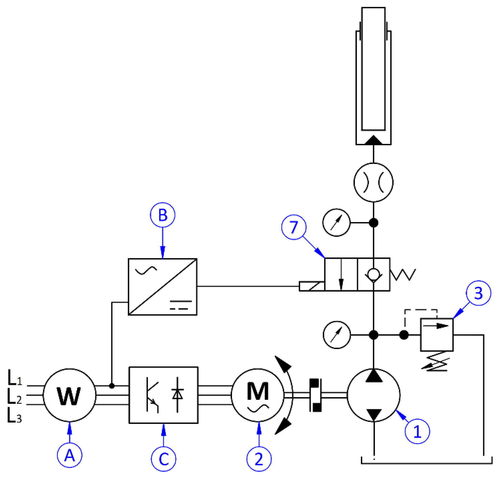
Figure 2 shows the EHD with a hydraulic reversible gear pump (1), driven by an AC asynchronous motor (2), fed by a frequency inverter (C). A pressure relief valve (3) limits pressure in the system. The two-way normally closed poppet valve (7) is used to choose the direction of movement of the hydraulic cylinder piston rod. Similarly, for the conventional drive, the system is equipped with a network parameter analyzer (A) and a power supply box (B). Lifting requires the frequency inverter that drives the motor to be powered. While lowering, the valve coil and the frequency inverter are powered simultaneously. Gravity causes the hydraulic cylinder to fall, and the fluid’s energy drives a pump that acts as a hydraulic motor. The pump pushes the asynchronous motor that acts as a generator. The frequency inverter generates the appropriate braking torque that maintains the set motor speed. In the tested system, the frequency inverter is not equipped in the regenerative power unit. The potential energy is lost on the resistor installed in the frequency inverter. It prevents energy from flowing into the electrical network, i.e., measuring power values below 0.
Both circuits are equipped with the same set of sensors. Measurement and recording are possible thanks to a program developed using LabView software. Both systems engage the same setup of the motor-pump unit (MPU) to obtain convergent results. The list of elements and parameters used in tests and analysis are shown in Table 1 and Table 2, respectively.
3. Description of Energy Consumption
Energy is an integral of the power in a definition of time (1). Hence, to estimate the energy consumption, the integration of the power function was conducted according to the following equation:
In the tested systems, the recorded power is a component of many elements. In hydraulic systems, the usable power is generated by an actuator. In this case, it is the hydraulic cylinder acting on the structure of the scissor lift. The hydraulic cylinder’s power can be estimated according to Equation (2) based on the data collected from the sensors.
The power generated by the hydraulic pump can be assessed according to Equation (3).
According to Equation (4), estimating the motor’s power consumption can be calculated based on magnitudes related directly to the electric motors.
Because of the scissor system’s variable ratio, the force developed by the hydraulic cylinder changes as a function of its stroke. Hence, the powers of individual elements will change during the operation of the lift. Moreover, elements consume an instantaneous constant power. All of the values of the efficiencies used in Equations (2)–(4) were investigated in [38]. Engagement of the set of sensors in the tested systems enables the continuous recording of magnitudes required to solve Equations (2) and (4). Thanks to this, instantaneous powers and energies at specific points of the drive are assessed.
4. Experimental Tests
4.1. Total Power and Energy Consumption
Preliminary tests were carried out for two systems presented in the above description for the same conditions:
- mass of the cargo on the platform mQ = (0, 48, 96, 192) kg;
- displacement of the scissor lift platform xp = 2 m;
- lifting depending on the system:
- ○
- speed of the motor according to its mechanical characteristics (conventional drive);
- ○
- speed of the motor nm = 1500 rpm (EHD);
- lowering depending on the system:
- ○
- via throttle valve (conventional drive);
- ○
- speed of the motor nm = 1500 rpm (EHD).
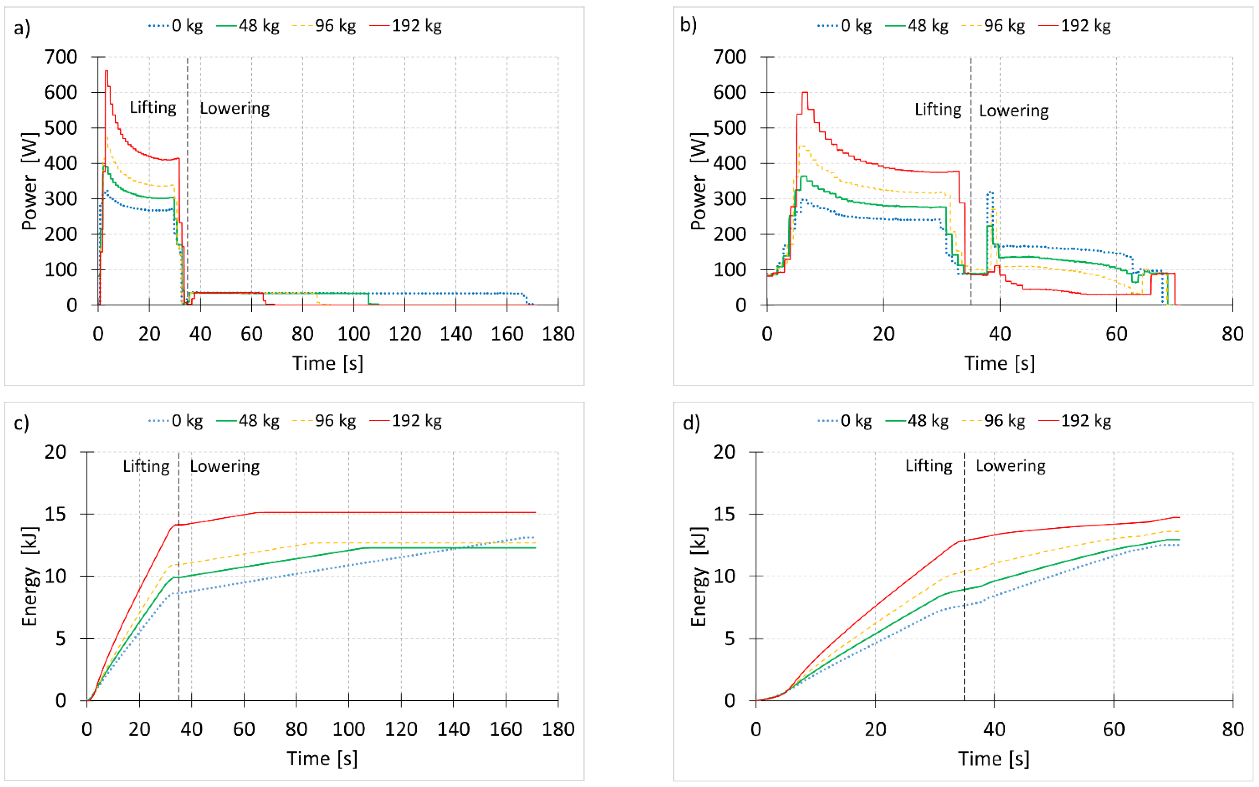
The hydraulic scissor lift’s work cycle consists of three stages: lifting phase, 5 s pause at the top position, and lowering phase. All data were collected throughout the cycle, regardless of its duration.
The instantaneous power and accumulated energy consumption plotted in Figure 3 are obtained from the measurements and Equation (1), respectively. The tests results for a conventional drive are shown in Figure 3a,c. The directional valve coils are powered for both lifting and lowering. Therefore, the system generates energy losses, even though the motor is not powered. It increases energy consumption throughout the cycle, reaching a value of over 15 kJ. In addition, the potential energy during lowering was converted into heat in the throttle valve and significantly increased cycle time with smaller loads. Surprisingly, the analysis results show that lowering the empty lift is more energy-consuming than with a load of 48 and 96 kg. The decisive factor here was the constant power loss resulting from the valve coil’s long active time during lowering.
The results for the hydraulic scissor lift with the proposed EHD are shown in Figure 3b,d. By replacing the directional valve with a 2/2 valve, power to this valve coil is only necessary while lowering. Although the electric motor is powered in both directions of the hydraulic cylinder, it is possible to reduce energy consumption. This is due to the electric motor operating as a generator. In the tested system, energy consumption during the full cycle reached 14 kJ. Despite the lack of a return module or energy storage module, a 2 kJ reduction in energy consumption (13%) with nominal capacity (192 kg) is noticeable despite the low lifting capacity of the scissor lift. Moreover, the EHD allows control of the speed of the mechanism and reduces the impact of dynamic forces and extends the service life of the machine, among others. Additionally, it shortened the cycle time, which was similar regardless of the load. The EHD appears to be energy-efficient while working without load and with nominal capacity of the scissor lift. Further research in this paper will reveal what affects total power consumption and which factor is crucial.
4.2. Power Demand of Individual Elements
Using the energy-measuring system, which is depicted in Figure 1 and Figure 2, the power consumption was investigated in a few conventional drive cases. The results of this investigation can be observed in Figure 4a. During the test, successive elements of the power system were turned on under the typical preparation of the lift for a full cycle. At the stage when the motor was running, the directional valve coil was not powered. The motor worked with the 4/3 directional valve turned off, pumping the oil through the bypass to the tank. One of the coils of this valve’s power demand is shown in the next step of the test.
Identical studies were carried out for the EHD (Figure 2). The individual power functions were turned on in sequence, as is the case in a normal cycle (Figure 4b). In standby mode, the frequency inverter is additionally powered, hence the slightly higher power consumption (8.2 W) than in a conventional system (4.5 W). Motor movement is released here via a frequency inverter in vector mode. Its algorithm calculates what braking torque should be generated so that the system can remain motionless. The result is high power consumption, reaching over 80 W. When lowering the scissor lift, the 2/2 valve coil should be powered, which additionally generates a demand of approx. 30 W.
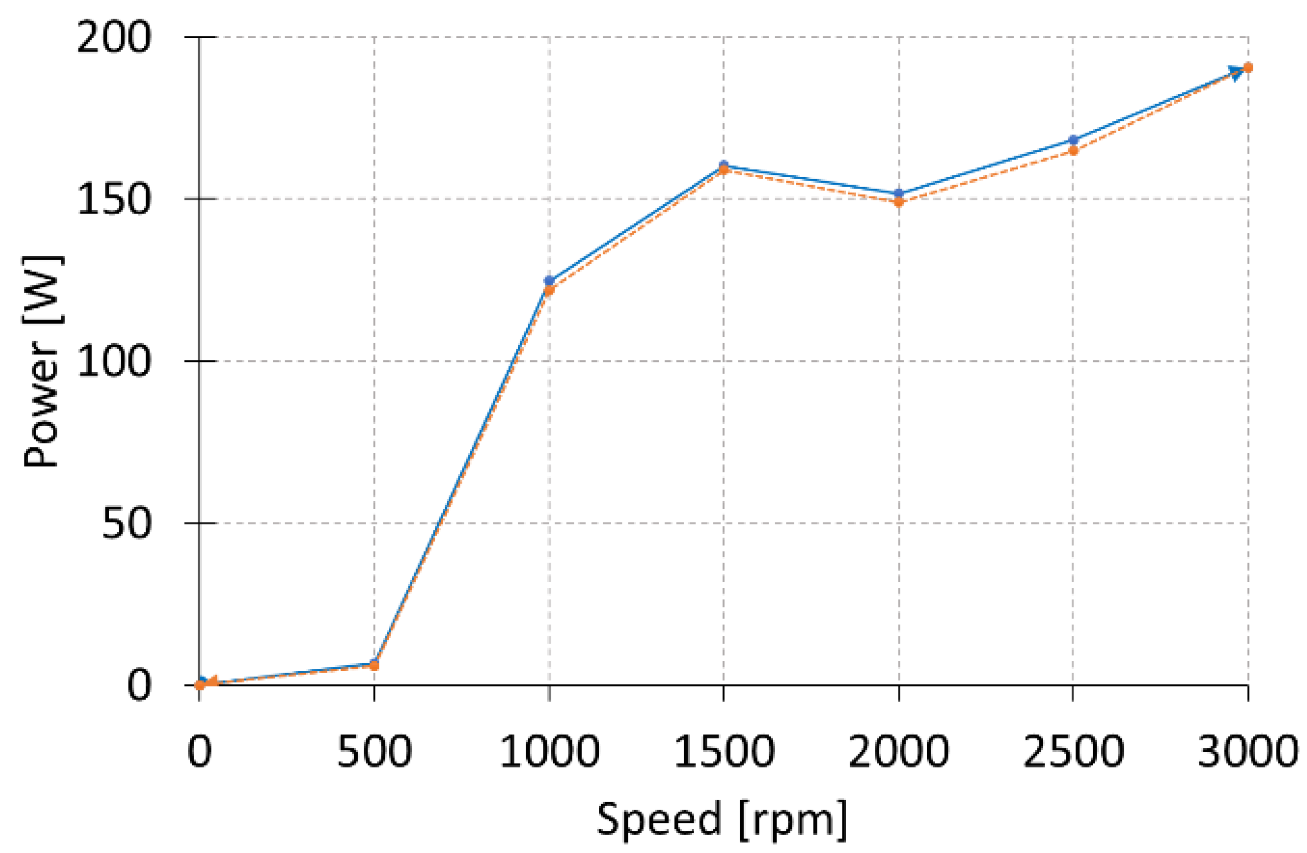
Another test was carried out to determine the power consumption of the MPU that operates at different rotational speeds. By changing the rotational speed of the motor with a frequency inverter, the power consumption was measured. During the investigation, the oil was going through the 4/3 directional valve in neutral position with a pressure caused by the resistance of the flow (pressure lower than 0.1 MPa). Taking measurements during increasing and decreasing the MPU speed, the hysteresis of power consumption was registered. The hysteresis is presented in Figure 5. The unexpected drop in power consumption at 2000 rpm may be due to resonance caused by the vibration of the pump gears. This is just a hypothesis that requires deeper analysis. In this work, to be sure of the measurements, the electric motor was operated at lower speeds.
5. Results of Energy Consumption Investigation
Based on the analysis of the power consumption of individual elements of the power supply system and the installed sensors on the experimental stand, it was possible to determine the tested system’s energy flow. A summary of the energy consumption within a cycle (lifting and lowering) in both drives with different loads is shown in Figure 6. The energy consumption of coils, standby, and MPU is based on the above measurements and shown in Figure 4. Effective energy is that which the hydraulic cylinder generates to lift the load (in both drives) and that which the hydraulic cylinder drives the pump when lowering (EHD). In the conventional drive, it is lost as heat at the throttle valve. The effective energy was calculated using sensors according to Equation (5). Pc was computed from Equation (2) with data measured from the sensors.
The hydraulic losses between the hydraulic cylinder and the pump were calculated according to the following Equation (6). Pm was computed from Equation (4) with data measured from the sensors.
The sum of energy components is shown as Total. As can be seen in low-load systems, each component has a significant impact on total energy consumption. The high energy consumption of the directional valve coils is remarkable.
In further analysis, energy consumption was divided into two components—constant and variable. The first one includes standby mode, supply to valve coils, MPU, and frequency inverter energies. These magnitudes are the result of the duration of the cycle. It is worth paying attention to how much energy these elements consume within an hour of work (Figure 7). The total energy consumption is 715 kJ (about 0.20 kWh). The consumption of the MPU is of particular interest. Still, many systems are designed such that the motor runs continuously without load. This dramatically increases the energy consumption of these devices. The second group includes effective power, hydraulic losses, and power required to generate the appropriate torque on the motor shaft. They result from the transported load.
The energy losses were summed up and compared with the motor’s energy to illustrate the energy consumption between these components in the scissor lift’s entire duty cycle—lifting and lowering (Figure 8). All losses were estimated according to Equation (7).
This summary shows that the motor needs only 42% of the total energy supplied (conventional drive with 192 kg of load). The use of the EHD reduced the energy consumption of the motor to less than 15%. This is due to the energy flow from the hydraulic cylinder to the motor as the scissor lift is lowered. Moreover, this overview shows how much power is consumed by typical supply components.
That mainly determines the energy consumption of low-load hydraulic lifts. It is especially evident in scissor lifts. As a result of the structure’s geometry, the power required to lift the load reaches its maximum in the lift’s folded position. The power decreases a dozen times as the lift rises.
6. Conclusions
In this paper, the energy consumption of a scissor lift was investigated. The two types of propulsion solutions in the machine were compared. The propulsion’s first solution is a standard one based on the electro-hydraulic circuit with a fixed displacement pump driven by an AC asynchronous motor. The propulsion system’s second, modified, solution engages the frequency inverter to the AC asynchronous motor and replaces the 4/3 directional and throttle valve with a two-way normally closed poppet valve. Energy consumption of the EHD is 10% lower than in standard drive. Moreover, the modification allows for recovering the energy of gravity while the cylinder falls, and the oil pushes the asynchronous motor to run. The analysis includes the energy losses generated on the valve coils, frequency inverter, MPU, and hydraulic losses.
EHD is more expensive than the standard one by about 100 EUR. The price difference is caused by the replacement of the 4/3 directional valve (c.a. EUR 150) and the one-way throttling check valve (c.a. EUR 20) with a 2/2 solenoid operated check valve (c.a. EUR 100) and frequency inverter (c.a. EUR 160).
The research showed the existence of energy losses in the drive system, which result from the energy consumption of individual elements of the power supply, control, and drive systems. A decrease in the percentage of energy losses with the increase in the mass handled was observed. This led to the conclusion that the enhancement of propulsion systems in scissor lifts should be especially considered in machines carrying big loads. However, when comparing the working cycles with different loads, it was found that in the EHD, the energy losses were equal or less than in the conventional system.
It can also be concluded that energetic savings can be obtained in the duty cycle by engaging the frequency inverter with the energy recovery system to the drive. Thanks to the bidirectional energetic flow, the motor in the modernized propulsion system consumes about 67% of the energy of the standard one.
The EHD allows us to control the speed of the mechanism and reduces the impact of dynamic forces and extends the service life of the machine.
This study’s results are crucial, especially in industrial facilities, where sustainable production or transportation occurs. An example is a technological line engaging scissor lifts or other hydraulic devices. Modernization of drives should be focused on adding the frequency inverters to asynchronous motors. Frequency inverters should be connected on the common DC link bus. The connection allows the swapping of the energy surplus between drives. Moreover, the power regeneration unit may be installed in the drive system to put the energy back into the electrical network.
Author Contributions
Conceptualization, L.S. and A.K.; methodology, L.S.; software, A.M.; validation, L.S., A.K. and J.Z.; formal analysis, A.K.; investigation, L.S.; resources, J.S.; data curation, A.M.; writing—original draft preparation, L.S.; writing—review and editing, J.Z.; visualization, L.S.; supervision, A.K.; project administration, L.S.; funding acquisition, J.S. and J.Z. All authors have read and agreed to the published version of the manuscript.
Funding
This research received no external funding.
Institutional Review Board Statement
Not applicable.
Informed Consent Statement
Not applicable.
Data Availability Statement
Not applicable.
Acknowledgments
The second and fourth authors would like to acknowledge the financial support from the project co-financed by the European Union under the European Social Fund as a part of the Operational Program: Knowledge, Education, Development, project No. POWR.03.02.00-0-I042/16-00.
Conflicts of Interest
The authors declare no conflict of interest.
References
- Huova, M.; Linjama, M.; Huhtala, K. Energy Efficiency of Digital Hydraulic Valve Control Systems; SAE Technical Paper; SAE International: Warrendale, PA, USA, 2013. [Google Scholar] [CrossRef]
- Xia, L.; Quan, L.; Ge, L.; Hao, Y. Energy efficiency analysis of integrated drive and energy recuperation system for hydraulic excavator boom. Energy Convers. Manag. 2018, 156, 680–687. [Google Scholar] [CrossRef]
- An, K.; Kang, H.; An, Y.; Park, J.; Lee, J. Methodology of Excavator System Energy Flow-Down. Energies 2020, 13, 951. [Google Scholar] [CrossRef] [Green Version]
- Stump, P.M.; Keller, N.; Vacca, A. Energy Management of Low-Pressure Systems Utilizing Pump-Unloading Valve and Accumulator. Energies 2019, 12, 4423. [Google Scholar] [CrossRef] [Green Version]
- Ranjan, P.; Wrat, G.; Bhola, M.; Mishra, S.K.; Das, J. A novel approach for the energy recovery and position control of a hybrid hydraulic excavator. ISA Trans. 2020, 99, 387–402. [Google Scholar] [CrossRef] [PubMed]
- Chen, Q.; Lin, T.; Ren, H.; Fu, S. Novel potential energy regeneration systems for hybrid hydraulic excavators. Math. Comput. Simul. 2019, 163, 130–145. [Google Scholar] [CrossRef]
- Minav, T.; Immonen, P.; Laurila, L.; Vtorov, V.; Pyrhönen, J.; Niemelä, M. Electric energy recovery system for a hydraulic forklift–theoretical and experimental evaluation. IET Electr. Power Appl. 2011, 5, 377. [Google Scholar] [CrossRef]
- Wang, H.; Wang, Q.; Hu, B. A review of developments in energy storage systems for hybrid excavators. Autom. Constr. 2017, 80, 1–10. [Google Scholar] [CrossRef]
- Latas, W.; Stojek, J. A new type of hydrokinetic accumulator and its simulation in hydraulic lift with energy recovery system. Energy 2018, 153, 836–848. [Google Scholar] [CrossRef]
- Donkov, V.; Andersen, T.; Ebbesen, M.; Pedersen, H. Applying Digital Hydraulic Technology on a Knuckle Boom Crane. In Proceedings of the Ninth Workshop on Digital Fluid Power, Aalborg, Denmark, 7–8 September 2017. [Google Scholar]
- Amico, D.A.; Carlsson, M.; Norlin, E.; Sethson, M. Investigation of a Digital Hydraulic Actuation System on an Excavator Arm. In Proceedings of the 13th Scandinavian International Conference on Fluid Power, Linköping, Sweden, 3–5 June 2013; Volume 92, pp. 505–511. [Google Scholar]
- Wang, T.; Wang, Q.; Lin, T. Improvement of boom control performance for hybrid hydraulic excavator with potential energy recovery. Autom. Constr. 2013, 30, 161–169. [Google Scholar] [CrossRef]
- Lin, T.; Wang, Q.; Hu, B.; Gong, W. Research on the energy regeneration systems for hybrid hydraulic excavators. Autom. Constr. 2010, 19, 1016–1026. [Google Scholar] [CrossRef]
- Bedotti, A.; Campanini, F.; Pastori, M.; Riccò, L.; Casoli, P. Energy saving solutions for a hydraulic excavator. Energy Procedia 2017, 126, 1099–1106. [Google Scholar] [CrossRef]
- Hao, Y.; Quan, L.; Cheng, H.; Xia, L.; Ge, L.; Zhao, B. Potential energy directly conversion and utilization methods used for heavy duty lifting machinery. Energy 2018, 155, 242–251. [Google Scholar] [CrossRef]
- Wang, T.; Wang, Q. Efficiency analysis and evaluation of energy-saving pressure-compensated circuit for hybrid hydraulic excavator. Autom. Constr. 2014, 47, 62–68. [Google Scholar] [CrossRef]
- Liu, B.; Quan, L.; Ge, L. Research on the performance of hydraulic excavator boom based pressure and flow accordance control with independent metering circuit. Proc. Inst. Mech. Eng. Part E J. Process. Mech. Eng. 2016, 231, 901–913. [Google Scholar] [CrossRef]
- Ge, L.; Quan, L.; Zhang, X.; Zhao, B.; Yang, J. Efficiency improvement and evaluation of electric hydraulic excavator with speed and displacement variable pump. Energy Convers. Manag. 2017, 150, 62–71. [Google Scholar] [CrossRef]
- Li, W.; Wu, B.; Cao, B. Control strategy of a novel energy recovery system for parallel hybrid hydraulic excavator. Adv. Mech. Eng. 2015, 7. [Google Scholar] [CrossRef] [Green Version]
- Manner, J.; Lindroos, O.; Arvidsson, H.; Nordfjell, T. Evaluation of a New Energy Recycling Hydraulic Lift Cylinder for Forwarders. Croat. J. For. Eng. 2016, 37, 219–231. [Google Scholar]
- Krakowski, T.; Ruta, H. Analysis and Assessment OF Energy Efficiency of Passenger Lifts. Adv. Sci. Technol. Res. J. 2018, 12, 257–265. [Google Scholar] [CrossRef]
- De Almeida, A. Options to Improve Lift Energy Efficiency; Tech. Rep.; Italian National Agency for New Technologies, Energy and Sustainable Economic Development: Roma, Italy, 2010. [Google Scholar] [CrossRef]
- Patrao, C.; Fong, J.; de Almeida, A.; Rivet, L. Energy Efficient Elevators and Escalators. In Proceedings of the Conference ECEEE 2009 Summer Study on energy efficiency: Act! Innovate! Deliver! Reducing Energy Demand Sustainably, La Colle sur Loup, France, 1–6 June 2009. [Google Scholar]
- Yang, H.; Sun, W.; Xu, B. New Investigation in Energy Regeneration of Hydraulic Elevators. IEEE/ASME Trans. Mechatron. 2007, 12, 519–526. [Google Scholar] [CrossRef]
- Koitto, T.; Kauranne, H.; Calonius, O.; Minav, T.; Pietola, M. Experimental Study on Fast and Energy-Efficient Direct Driven Hydraulic Actuator Unit. Energies 2019, 12, 1538. [Google Scholar] [CrossRef] [Green Version]
- Minav, T.A.; Laurila, L.I.; Pyrhönen, J.J. Analysis of electro-hydraulic lifting system’s energy efficiency with direct electric drive pump control. Autom. Constr. 2013, 30, 144–150. [Google Scholar] [CrossRef]
- Minav, T.; Hänninen, H.; Sinkkonen, A.; Laurila, L.; Pyrhönen, J. Electric or Hydraulic Energy Recovery Systems in a Reach Truck– A Comparison. Stroj. Vestn. J. Mech. Eng. 2014, 60, 232–240. [Google Scholar] [CrossRef]
- Mahmood, A.; Almaged, M.; Ismael, O.Y. Quantitative Design Analysis of an Electric Scissor Lift. Am. Sci. Res. J. Eng. Technol. Sci. 2009, 59, 128–141. [Google Scholar]
- Ciupan, C.; Ciupan, E.; Pop, E. Algorithm for designing a hydraulic scissor lifting platform. MATEC Web Conf. 2019, 299, 3012. [Google Scholar] [CrossRef] [Green Version]
- Chaturvedi, A.; Mishra, J.; Parmar, V. An Improved Scissor Lift working on Lead Screw Mechanism Aerial Scissor Lift and its Accessories. Int. J. Adv. Eng. Res. Dev. 2017, 4, 89–95. [Google Scholar]
- Burian, M.; Havlik, J.; Folta, Z.; Trochta, M.; Maršálek, P. Solution the Drive Lifting Scissor Platforms. In Proceedings of the 16th Asian Congress of Fluid Mechanics, Bangalaore, India, 3 April 2014; pp. 19–26. [Google Scholar]
- Dong, R.G.; Pan, C.S.; Hartsell, J.J.; Welcome, D.E.; Lutz, T.; Brumfield, A.; Harris, J.R.; Wu, J.Z.; Wimer, B.; Mucino, V.; et al. An Investigation on the Dynamic Stability of Scissor Lift. Open J. Saf. Sci. Technol. 2012, 2, 8–15. [Google Scholar] [CrossRef] [Green Version]
- Dengiz, C.G.; Şenel, M.C.; Yıldızlı, K.; Koc, E. Design and Analysis of Scissor Lifting System by Using Finite Elements Method. Univers. J. Mater. Sci. 2018, 6, 58–63. [Google Scholar] [CrossRef] [Green Version]
- Rani, D.; Agarwal, N.; Tirth, V. Design and Fabrication of Hydraulic Scissor Lift. MIT Int. J. Mech. Eng. 2015, 5, 81–87. [Google Scholar]
- Thorat S., G.; Chiddarwar A., R.; Prusty, P.S. Design and Construction of Hydraulic Scissor Lift. Int. J. Curr. Eng. Technol. 2017, 7, 32–95. [Google Scholar]
- Suresh, P.; Sivathanu, A. Fabrication of Hydraulic Scissor Lift. Int. J. Innov. Work. Eng. Technol. 2017, 3. [Google Scholar] [CrossRef]
- Stawiński, Ł.; Kosucki, A.; Morawiec, A.; Sikora, M. A new approach for control the velocity of the hydrostatic system for scissor lift with fixed displacement pump. Arch. Civ. Mech. Eng. 2019, 19, 1104–1115. [Google Scholar] [CrossRef]
- Stawiński, Ł.; Kosucki, A.; Morawiec, A. Hydrostatic Actuator Drive Control with Pump Leakage Compensation. In NSHP 2020: Advances in Hydraulic and Pneumatic Drives and Control 2020; Stryczek, J., Warzyńska, U., Eds.; Lecture Notes in Mechanical Engineering; Springer: Cham, Switzerland, 2021. [Google Scholar] [CrossRef]
Figure 1.
Hydraulic scheme of conventional scissor lift.
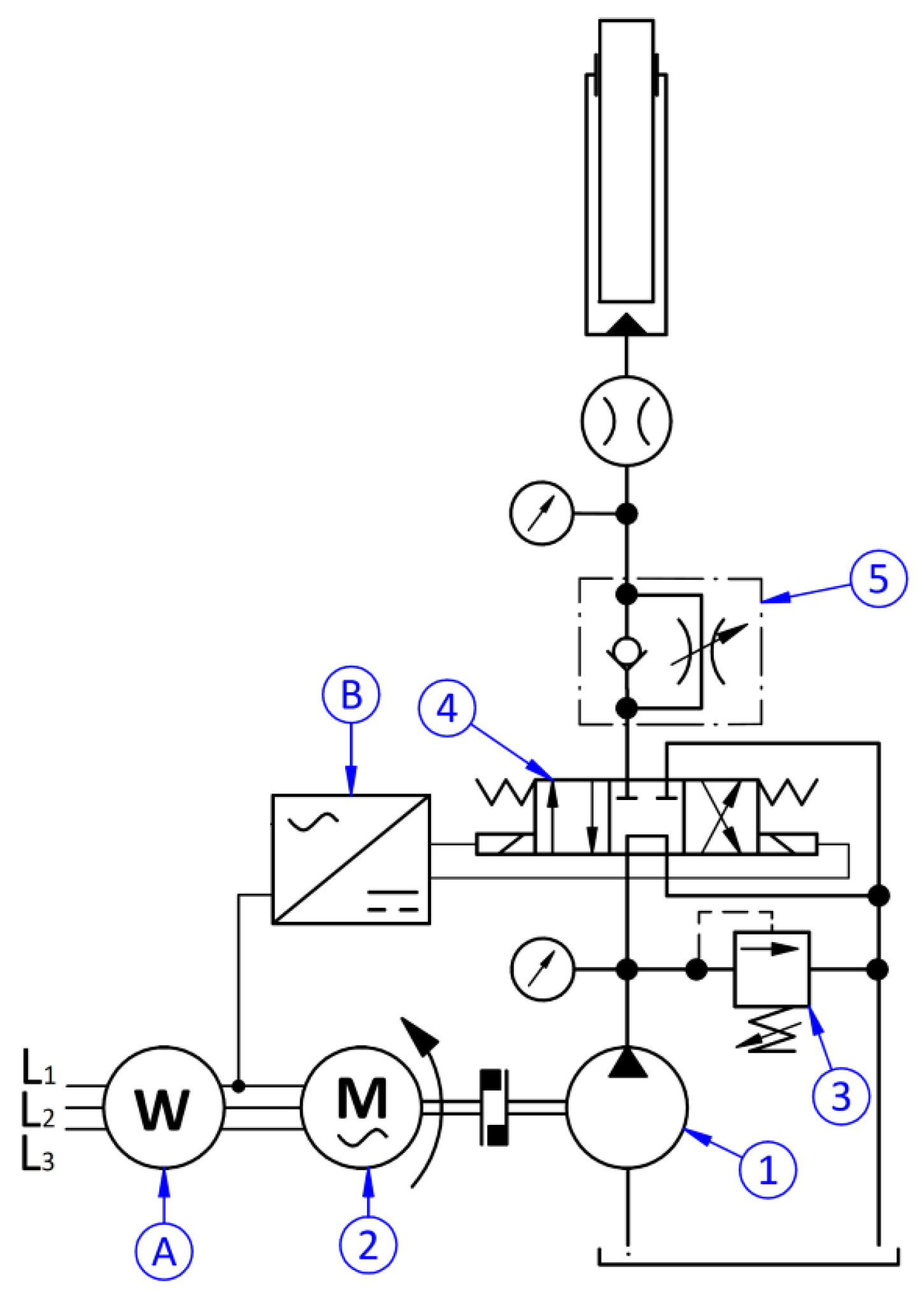
Figure 2.
Hydraulic scheme of electro-hydraulic drive (EHD).

Figure 3.
Comparison of the conventional drive (left) and EHD (right) in a duty cycle: (a,b) power consumption, (c,d) energy consumption.
Figure 3.
Comparison of the conventional drive (left) and EHD (right) in a duty cycle: (a,b) power consumption, (c,d) energy consumption.

Figure 4.
Power demand: (a) conventional drive, (b) EHD.
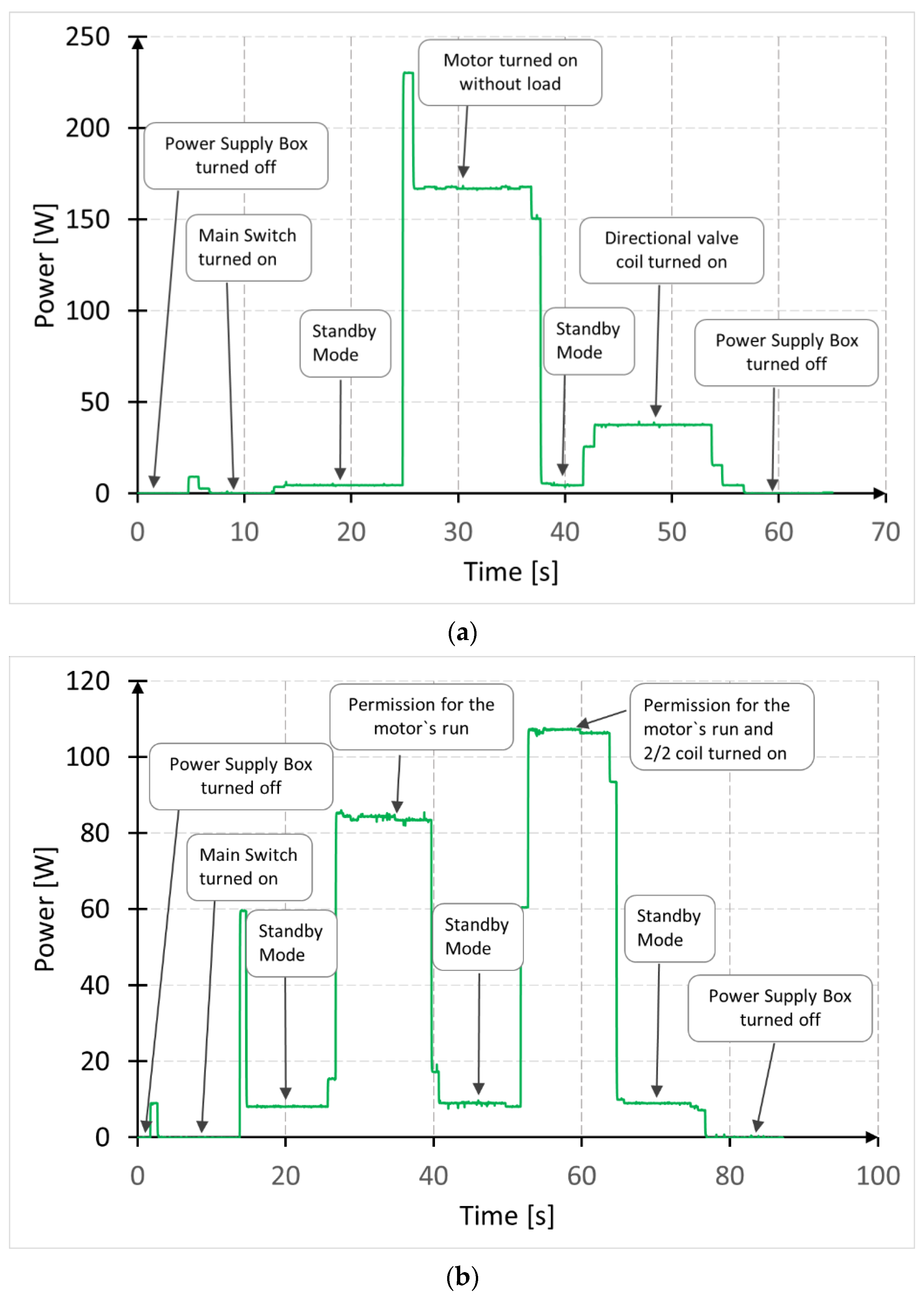
Figure 5.
Hysteresis of the motor-pump unit (MPU) power consumption at different rotational speeds.

Figure 6.
Energy consumption distribution: (a) conventional drive, (b) EHD.

Figure 7.
Energy consumption of constant components within an hour.
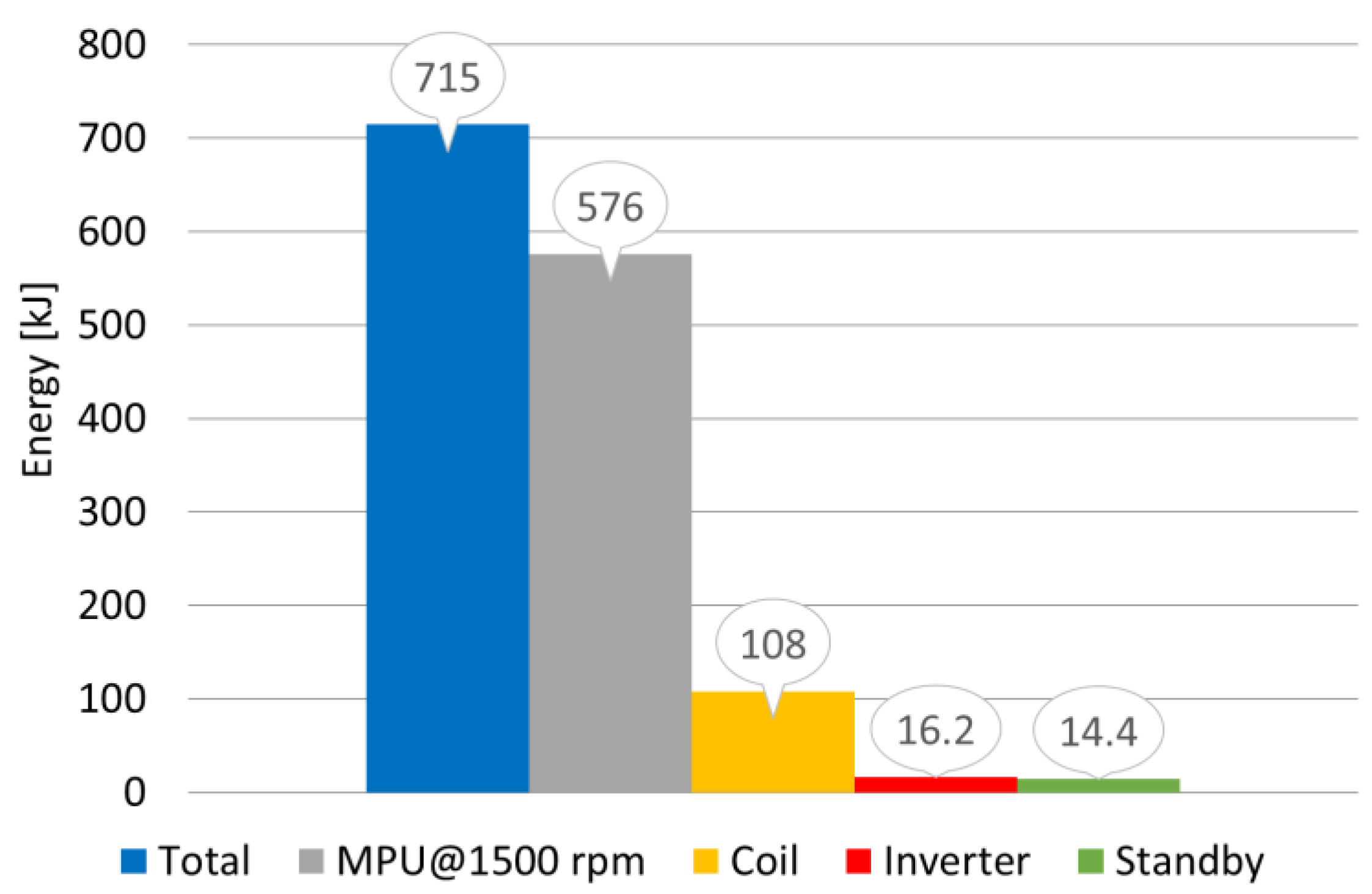
Figure 8.
Motor vs. all losses: (a) conventional drive, (b) EHD.


Table 1.
Parameters of the system.
| Component | Parameters |
|---|---|
| Nominal capacity | 192 kg |
| Pump XV-0R/0.98 | 0.92 cc/rev |
| Motor Simotics GP 1AV1082B | 0.55 kW/1385 rpm |
| Pressure relief valve VMP V0700 | 30 MPa/45 lpm |
| Directional control valve (4/3) HP-4WE6-G/D24-SR-Z5L | 36 MPa/80 lpm |
| Solenoid operated check valve (2/2) EP-08W-05-M-04 | 35 MPa/30 lpm |
| Throttle valve VRFU 9001 | 35 MPa/35 lpm |
| Power network analyzer LUMEL P43 | 5A/400V |
| Frequency inverter SX2400-0R7G-2 | 0.75 kW/0–10 V |
| Pressure sensors P3297B084001 | 25 MPa/4–20 mA |
| Flowmeter GFM-5 | 0.05–2 lpm/5.250 pulses/l |
Table 2.
Nomenclature.
| Symbol | Description | Unit |
|---|---|---|
| E | Energy | J |
| P | Power | W |
| Pc | Power of the hydraulic cylinder | W |
| Fc | Force on the hydraulic cylinder | N |
| pc | Inlet pressure of the hydraulic cylinder | Pa |
| ηc | Efficiency of the hydraulic cylinder | m/s |
| Pp | Power of the pump | W |
| pp | Inlet pressure of the pump | Pa |
| Qp | Outlet flow from the pump | m3/s |
| Qc | Cylinder inlet flow | m3/s |
| ηp | Efficiency of the pump | - |
| qp | Displacement of the pump | m3/rad |
| Pm | Power of the motor | W |
| Tm | Torque on the motor shaft | Nm |
| ωm | Angular motor velocity | rad/s |
| ηm | Efficiency of the motor | - |
| Eeff | Effective energy | J |
| Peff | Effective power | W |
| EHL | Energy of hydraulic losses | J |
| PHL | Power of hydraulic losses | W |
| EL | Energy of losses | J |
| EMPU | Energy of motor-pump unit | J |
| ECoil | Energy of valve coil | J |
| EStandby | Energy of standby mode | J |
| EInverter | Energy of frequency inverter | J |
Publisher’s Note: MDPI stays neutral with regard to jurisdictional claims in published maps and institutional affiliations. |
© 2021 by the authors. Licensee MDPI, Basel, Switzerland. This article is an open access article distributed under the terms and conditions of the Creative Commons Attribution (CC BY) license (http://creativecommons.org/licenses/by/4.0/).
Share and Cite
MDPI and ACS Style
Stawinski, L.; Zaczynski, J.; Morawiec, A.; Skowronska, J.; Kosucki, A. Energy Consumption Structure and Its Improvement of Low-Lifting Capacity Scissor Lift. Energies 2021, 14, 1366. https://doi.org/10.3390/en14051366
AMA Style
Stawinski L, Zaczynski J, Morawiec A, Skowronska J, Kosucki A. Energy Consumption Structure and Its Improvement of Low-Lifting Capacity Scissor Lift. Energies. 2021; 14(5):1366. https://doi.org/10.3390/en14051366
Chicago/Turabian StyleStawinski, Lukasz, Jakub Zaczynski, Adrian Morawiec, Justyna Skowronska, and Andrzej Kosucki. 2021. "Energy Consumption Structure and Its Improvement of Low-Lifting Capacity Scissor Lift" Energies 14, no. 5: 1366. https://doi.org/10.3390/en14051366
Note that from the first issue of 2016, this journal uses article numbers instead of page numbers. See further details here.