
A Review of Wearable Back-Support Exoskeletons for Preventing Work-Related Musculoskeletal Disorders

 ,
,
Abstract
1. Introduction
2. Methods
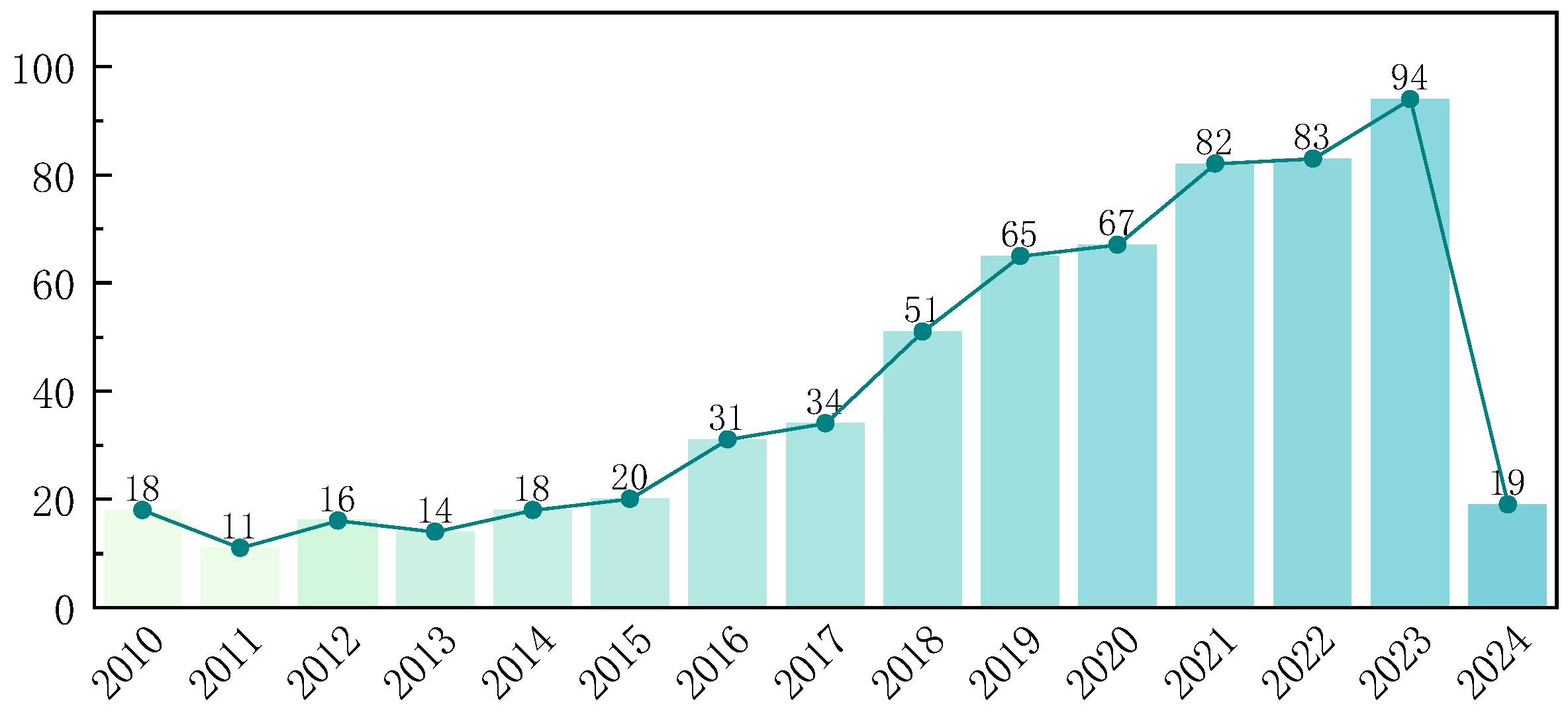
2.1. Search Strategy
2.2. Study Eligibility Selection
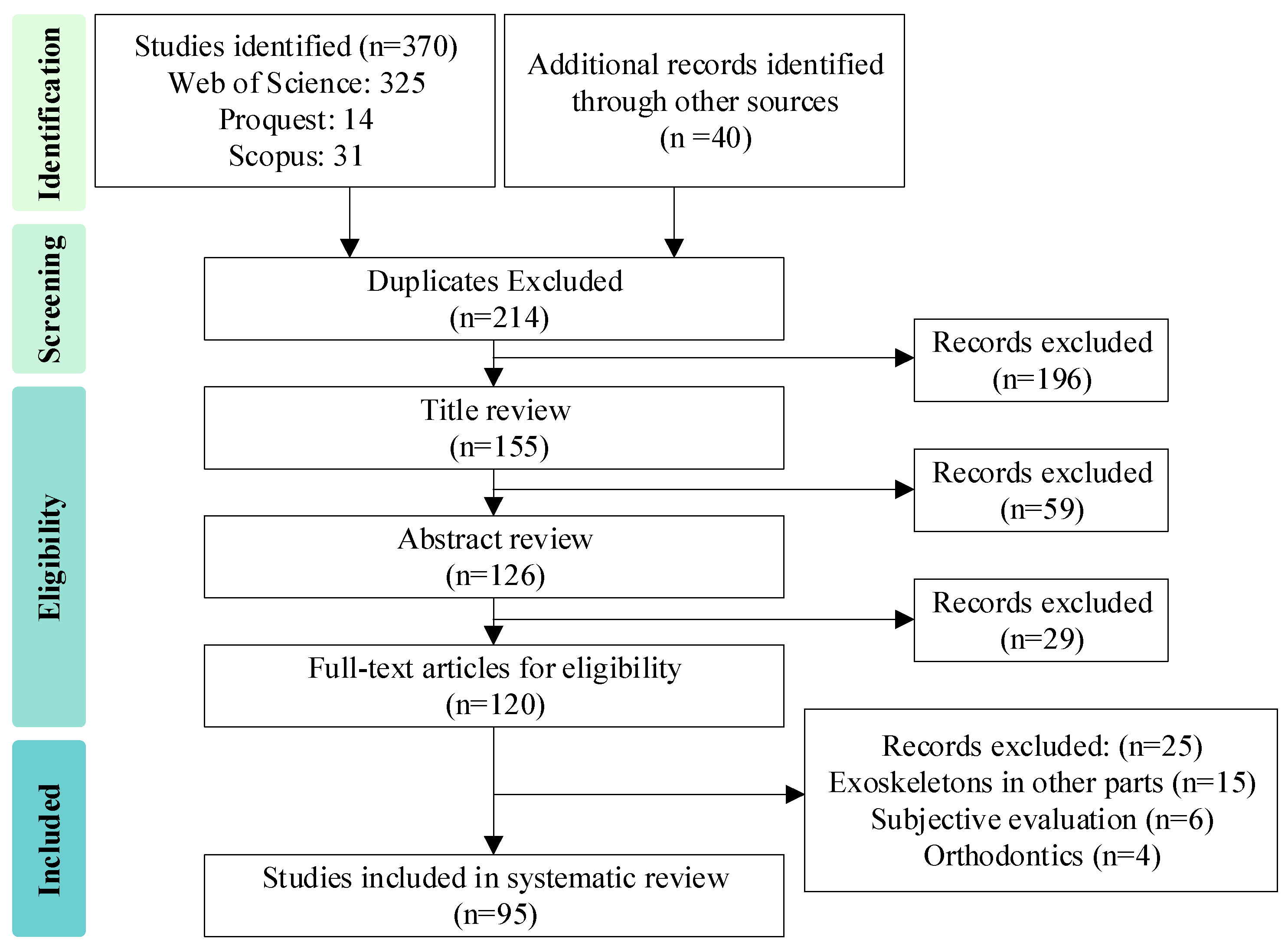
2.3. Study Screening
3. Results
3.1. Biomechanical Characterization Analysis
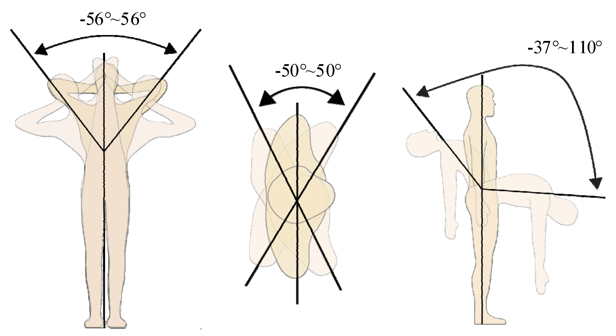
3.2. Joint Range of Motion
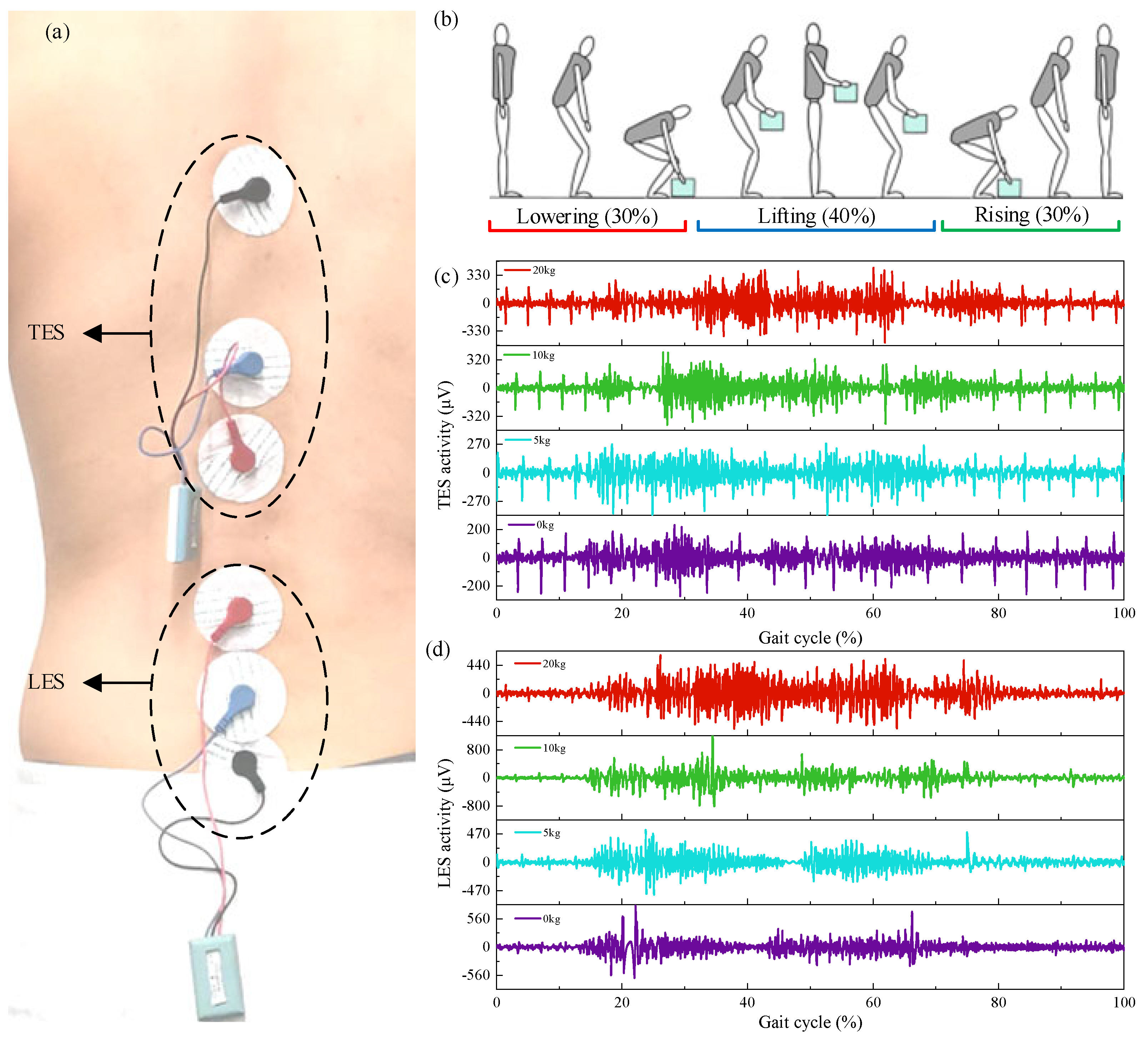
3.3. Biomechanical Analysis Based on Handling Movements
3.4. Powered Lumbar Spine Assist Exoskeleton
3.4.1. Rigid Lumbar Spine Assist Exoskeleton
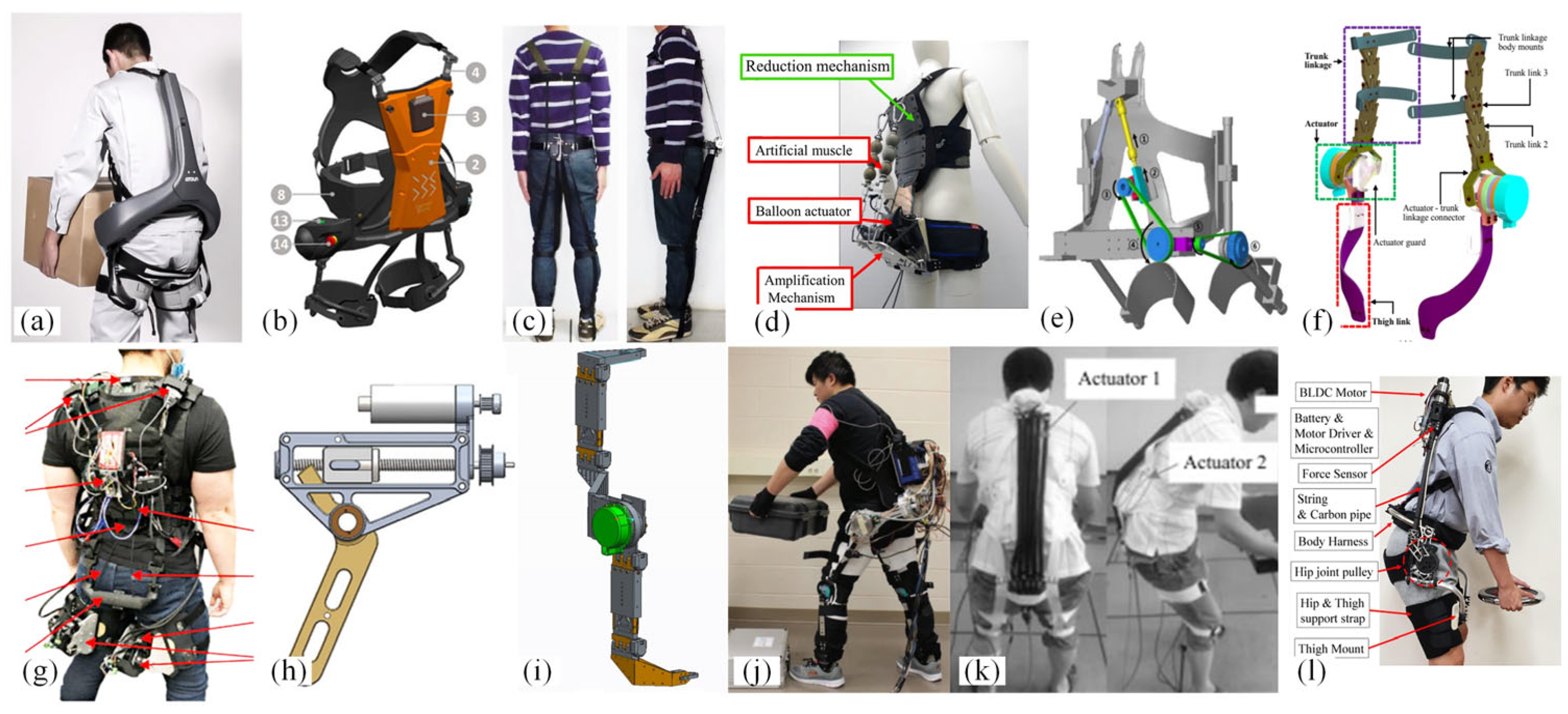
3.4.2. Flexible Lumbar Spine Assist Exoskeleton
3.5. Non-Powered Lumbar Spine Assist Exoskeleton
3.5.1. Belt Type
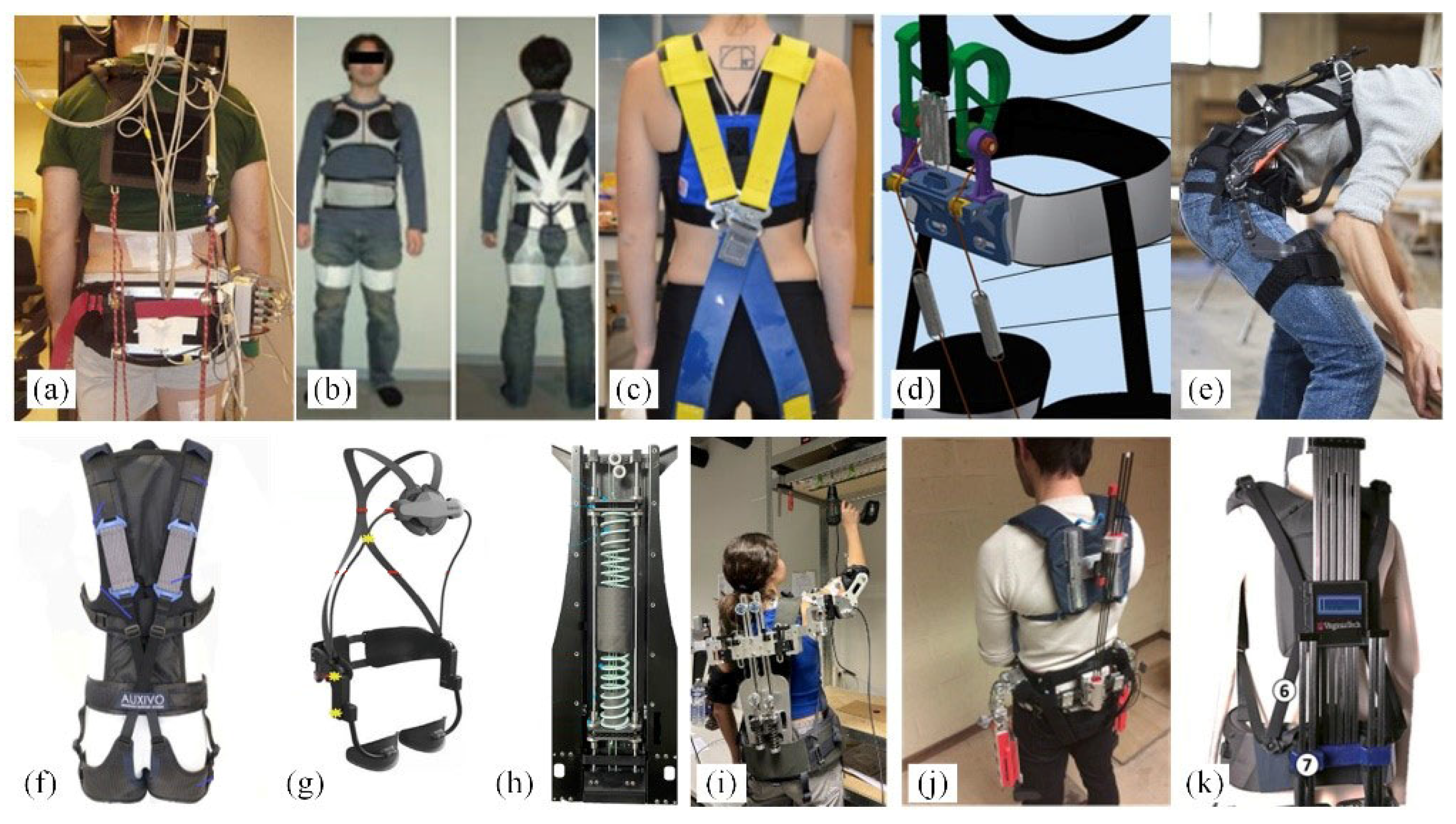
3.5.2. Spring Type
3.5.3. Elastic Beam Type
- (1)
- Limited assistance efficiency. The assistance provided by springs is difficult to control and depends solely on the bending angle, thus failing to offer sufficient assistance when lifting heavy objects.
- (2)
- Load transfer. Although they reduce the burden on the lower back, the load is transferred to the lower limbs, potentially affecting other muscles.
- (3)
- Comfort issues. Design elements such as constraints and limiting air cushions in exoskeletons may restrict freedom of movement and even cause discomfort in other muscles.
3.6. Quasi-Passive Lumbar Spine Assist Exoskeleton

4. Discussion
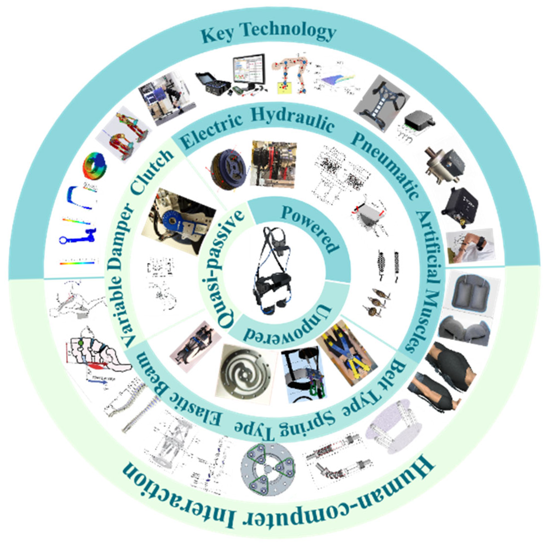
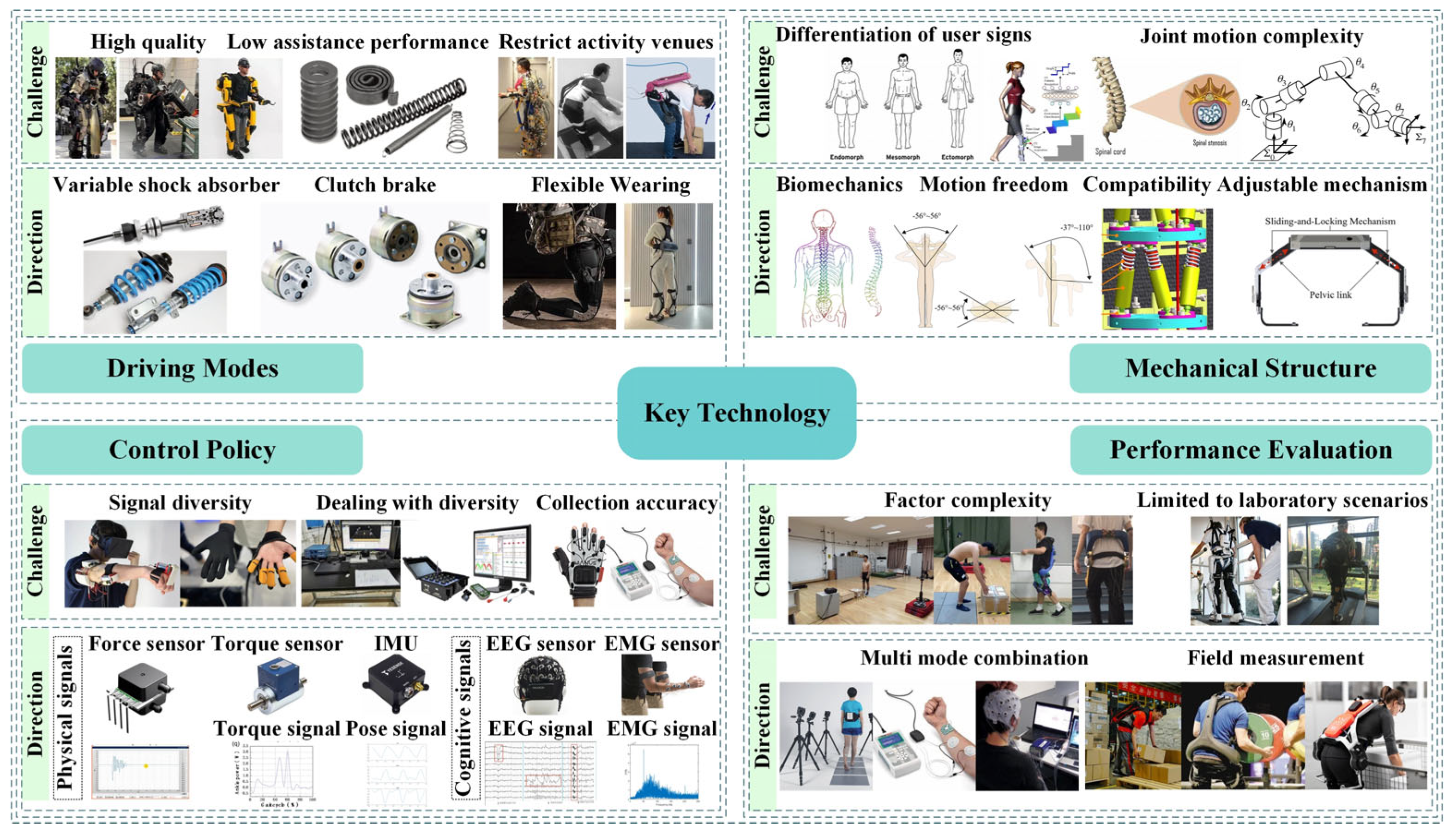
4.1. Driving Modes
4.2. Mechanical Structure
4.2.1. Actuation Transmission Mechanisms
4.2.2. Limitation Structures
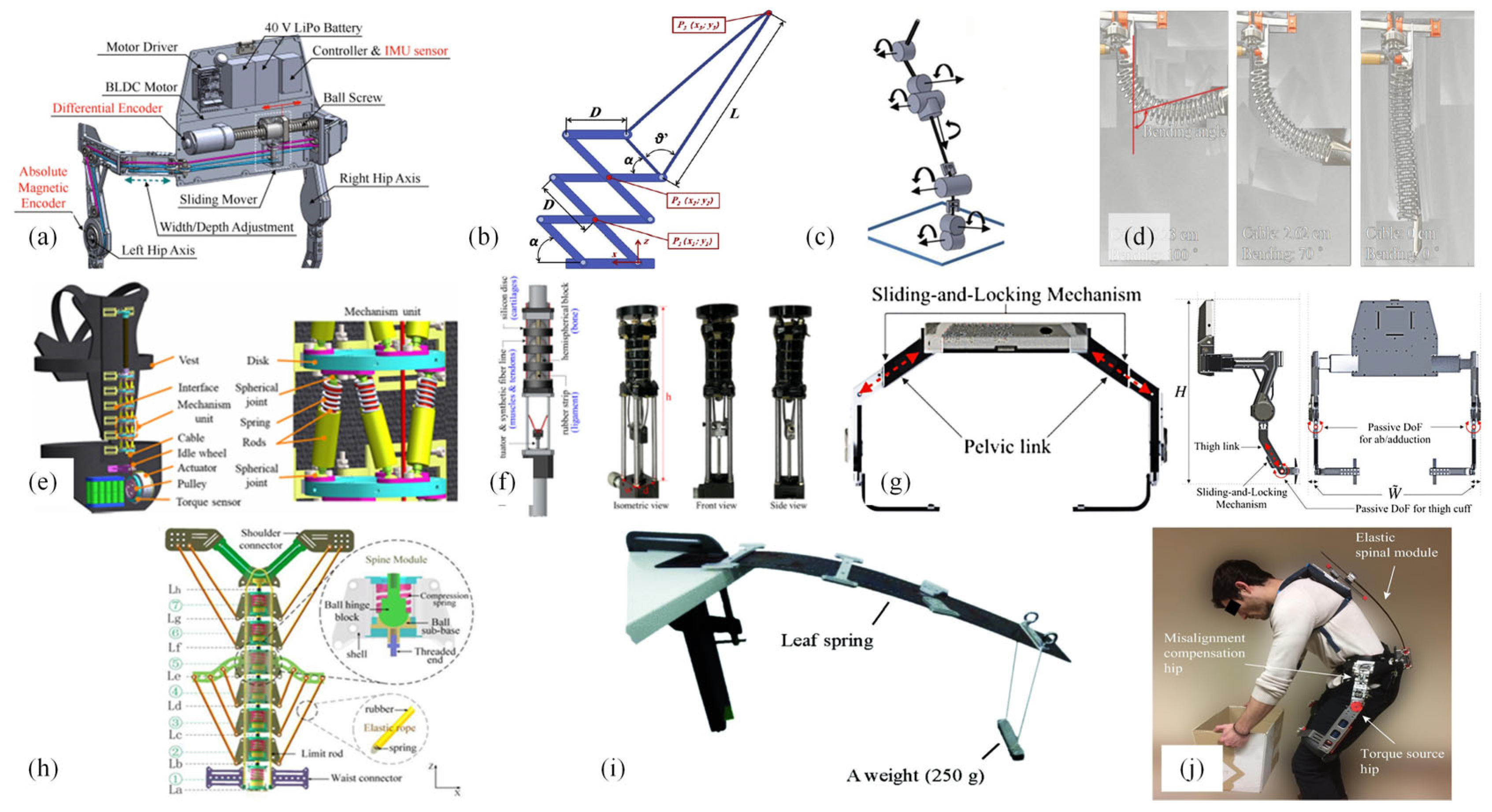
4.2.3. Supporting Structures
4.3. Control Policy
4.3.1. Perception of Human Motion Intent
- (1)
- Indirect Control
- (2)
- Direct Control
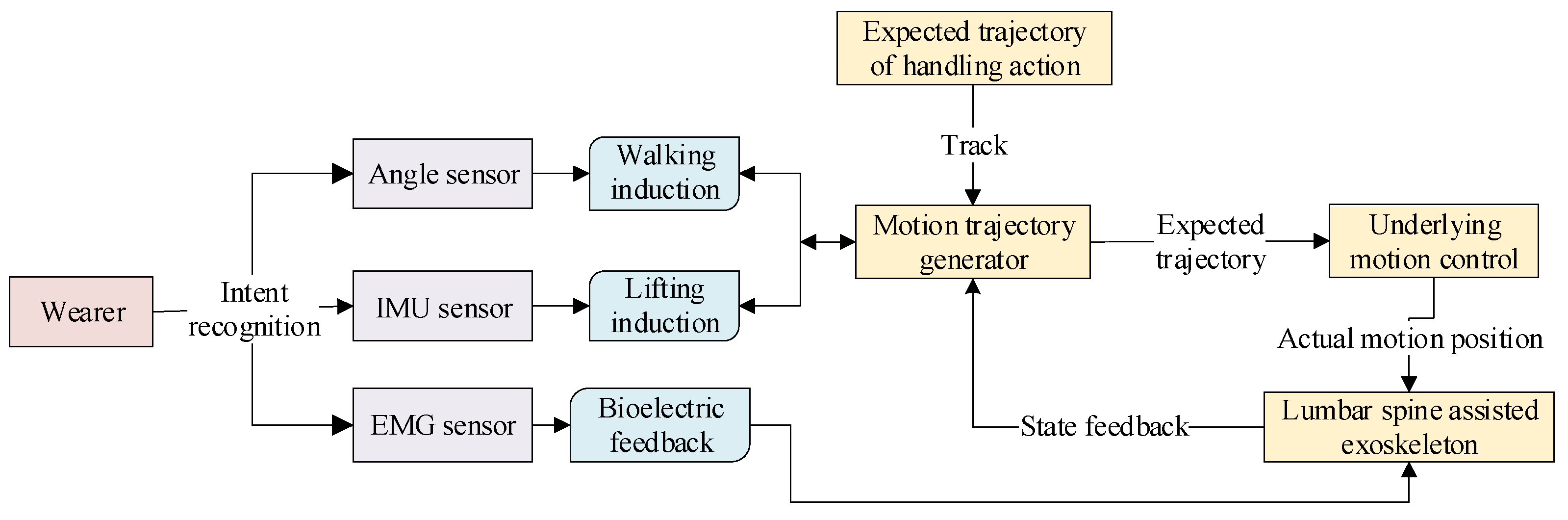
4.3.2. Human–Machine Collaborative Control Strategies
4.4. Performance Evaluation
5. Conclusions
- (1)
- In terms of drive systems, considering that the target users are often workers engaged in prolonged bending activities, it is crucial to minimize the fatigue induced by the exoskeleton on the wearer’s body. Therefore, the design of the drive system should prioritize characteristics such as light weight, compact size, and high efficiency. Unpowered exoskeletons rely solely on flexible/elastic structures to conform more closely to the wearer, but they also have limitations. Powered lumbar assistive exoskeletons, along with their corresponding assistive strategies, can offer more functionality, but their motors and transmission mechanisms tend to be bulky, leading to fatigue when used for extended periods in industrial settings. Hence, the design of exoskeleton drive systems should integrate the advantages of various drive modes. For example, leveraging parallel elastic actuators can reduce the size and weight of the device while meeting the required output torque.
- (2)
- In terms of mechanical structure design, the goal is to efficiently transmit assistance while minimizing unnecessary constraints and user discomfort. Existing exoskeletons primarily focus on sagittal plane movements, which, to some extent, restrict human activities. Therefore, enabling the unrestricted movement for the wearer is a primary concern. The choice of transmission structure depends on the driving mode. Currently, most electrically driven exoskeletons utilize rigid structures to transmit assistance, while unpowered exoskeletons mostly employ flexible structures for assistance, albeit with limited effectiveness. Hence, the design of exoskeleton mechanical structures can incorporate a combination of rigidity and flexibility. For example, exoskeletons such as Spexor [56] and Leavo [100] use rigid structures as the supporting part, with motors incorporating elastic components to transmit torque and absorb human energy for assistance, thereby expanding the range of human movement. Simultaneously, simplifying the power transmission mechanism can effectively reduce the weight of the exoskeleton [47].
- (3)
- In terms of control strategies, the majority of existing lumbar exoskeletons primarily provide assistance for lifting tasks (bending and squatting), yet workers’ postures in industrial settings also involve various movements such as walking, pushing, pulling, lifting, and carrying [83]. The design of exoskeletons should ensure that they can automatically identify moments when assistance is needed during different tasks performed by the wearer, without interfering with natural human motion. Device parameters should be adjusted according to different users, and if necessary, the exoskeleton operation can be manually halted to ensure operational safety.
- (4)
- In terms of human–machine interaction, firstly, regarding degrees of freedom, there should be sufficient freedom of movement to not constrain natural human motion. Secondly, concerning human–machine adaptation, efforts should maximize conformity to the articulation of human joints. Finally, lightweight design should consider the optimal selection of structure, size, and materials. Materials should prioritize lightness, breathability, flexibility, and high wearing comfort while meeting basic stiffness requirements. Novel smart materials have been introduced and successfully applied in existing exoskeletons [120]. However, currently, most exoskeletons have not considered the fatigue experienced by users during prolonged wear. Whether powered or unpowered, exoskeletons have a certain weight; after all, they are “external” skeletons and cannot truly integrate with the human body. The real-time intelligent monitoring of users’ fatigue levels while wearing exoskeletons may be a worthwhile direction for future development.
Author Contributions
Funding
Data Availability Statement
Conflicts of Interest
References
- Hsiang, S.M.; Brogmus, G.E.; Courtney, T.K. Low back pain (LBP) and lifting technique—A review. Int. J. Ind. Ergon. 1997, 19, 59–74. [Google Scholar] [CrossRef]
- Dos Anjos, F.V.; Ghislieri, M.; Cerone, G.L.; Pinto, T.P.; Gazzoni, M. Changes in the distribution of muscle activity when using a passive trunk exoskeleton depend on the type of working task: A high-density surface EMG study. J. Biomech. 2022, 130, 110846. [Google Scholar] [CrossRef]
- Cieza, A.; Causey, K.; Kamenov, K.; Hanson, S.W.; Chatterji, S.; Vos, T. Global estimates of the need for rehabilitation based on the Global Burden of Disease study 2019: A systematic analysis for the Global Burden of Disease Study 2019. Lancet 2020, 396, 2006–2017. [Google Scholar] [CrossRef]
- So, B.C.L.; Hua, C.; Chen, T.; Gao, Q.; Man, S.S. Biomechanical assessment of a passive back-support exoskeleton during repetitive lifting and carrying: Muscle activity, kinematics, and physical capacity. J. Saf. Res. 2022, 83, 210–222. [Google Scholar] [CrossRef]
- Hoy, D.; Brooks, P.; Blyth, F.; Buchbinder, R. The Epidemiology of low back pain. Best Pract. Res. Clin. Rheumatol. 2010, 24, 769–781. [Google Scholar] [CrossRef]
- Ganasegeran, K.; Perianayagam, W.; Nagaraj, P.; Al-Dubai, S.A.R. Psycho-behavioural risks of low back pain in railway workers. Occup. Med. 2014, 64, 372–375. [Google Scholar] [CrossRef]
- Ma, T.; Zhang, Y.; Choi, S.D.; Xiong, S. Modelling for design and evaluation of industrial exoskeletons: A systematic review. Appl. Ergon. 2023, 113, 104100. [Google Scholar] [CrossRef]
- Goršič, M.; Song, Y.; Dai, B.; Novak, V.D. Short-term effects of the Auxivo LiftSuit during lifting and static leaning. Appl. Ergon. 2022, 102, 103765. [Google Scholar] [CrossRef]
- Ji, X.; Wang, D.; Li, P.; Zheng, L.; Sun, J.; Wu, X. SIAT-WEXv2: A Wearable Exoskeleton for Reducing Lumbar Load during Lifting Tasks. Complexity 2020, 2020, 8849427. [Google Scholar] [CrossRef]
- Wang, D.; Lee, K.M.; Ji, J. A Passive Gait-Based Weight-Support Lower Extremity Exoskeleton with Compliant Joints. IEEE Trans. Robot. 2016, 32, 933–942. [Google Scholar] [CrossRef]
- Ugbolue, U.C.; Robson, C.; Donald, E.; Speirs, K.L.; Dutheil, F.; Baker, J.S.; Dias, T.; Gu, Y. Joint Angle, Range of Motion, Force, and Moment Assessment: Responses of the Lower Limb to Ankle Plantarflexion and Dorsiflexion. Appl. Bionics Biomech. 2021, 2021, e1232468. [Google Scholar] [CrossRef] [PubMed]
- Panero, E.; Muscolo, G.G.; Pastorelli, S.; Gastaldi, L. Influence of hinge positioning on human joint torque in industrial trunk exoskeleton. In Advances in Mechanism and Machine Science; Springer International Publishing: Cham, Switzerland, 2019; pp. 133–142. [Google Scholar]
- Bogue, R. Exoskeletons—A review of industrial applications. Ind. Robot Int. J. 2018, 45, 585–590. [Google Scholar] [CrossRef]
- Walter, T.; Stutzig, N.; Siebert, T. Active exoskeleton reduces erector spinae muscle activity during lifting. Front. Bioeng. Biotechnol. 2023, 11, 1143926. [Google Scholar] [CrossRef] [PubMed]
- Luo, Z.; Yu, Y. Wearable stooping-assist device in reducing risk of low back disorders during stooped work. In Proceedings of the 2013 IEEE International Conference on Mechatronics and Automation, Takamatsu, Kagawa, Japan, 4–7 August 2013; pp. 230–236. [Google Scholar]
- Inose, H.; Mohri, S.; Arakawa, H.; Okui, M.; Koide, K.; Yamada, Y.; Kikutani, I.; Nakamura, T. Semi-endoskeleton-type waist assist AB-wear suit equipped with compressive force reduction mechanism. In Proceedings of the 2017 IEEE International Conference on Robotics and Automation (ICRA), Singapore, 29 May 2017–3 June 2017; pp. 6014–6019. [Google Scholar]
- Shin, W.; Park, G.; Lee, Y.; Lee, J.; Kim, J. Development and Validation of Pneumatic Muscle based Back Assistance Exoskeleton. In Proceedings of the 2019 16th International Conference on Ubiquitous Robots (UR), Jeju, Republic of Korea, 24–27 June 2019; pp. 349–353. [Google Scholar]
- Perera, U.L.S.; Dasanayake, N.P.; Hettiarachchi, H.P.T.; Mazumdar, A.; Young, A.J. HipExo: A Hip Exoskeleton Robot for Load Lifting with Flexible Trunk Linkage Mechanism. In Proceedings of the 2020 Moratuwa Engineering Research Conference (MERCon), Moratuwa, Sri Lanka, 28–30 July 2020; pp. 614–619. [Google Scholar]
- Li, J.M.; Molinaro, D.D.; King, A.S.; Mazumdar, A.; Young, A.J. Design and Validation of a Cable-Driven Asymmetric Back Exosuit. IEEE Trans. Robot. 2022, 38, 1489–1502. [Google Scholar] [CrossRef]
- Martin, W.B.; Boehler, A.; Hollander, K.W.; Kinney, D.; Hitt, J.K.; Kudva, J.; Sugar, T.G. Development and testing of the aerial porter exoskeleton. Wearable Technol. 2022, 3, e1. [Google Scholar] [CrossRef]
- Toxiri, S.; Ortiz, J.; Masood, J.; Fernandez, J.; Mateos, L.A.; Caldwell, D.G. A wearable device for reducing spinal loads during lifting tasks: Biomechanics and design concepts. In Proceedings of the 2015 IEEE International Conference on Robotics and Biomimetics (ROBIO), Zhuhai, China, 6–9 December 2015; pp. 2295–2300. [Google Scholar]
- Zhang, T.; Huang, H. A Lower-Back Robotic Exoskeleton: Industrial Handling Augmentation Used to Provide Spinal Support. IEEE Robot. Autom. Mag. 2018, 25, 95–106. [Google Scholar] [CrossRef]
- Li, X.; Han, J.; Guo, B. Research on Wearable Lumbar Booster Robot Based on Flexible Pneumatic Driver. Acta Autom. Sin. 2016, 42, 1849–1858. [Google Scholar]
- Seong, H.S.; Kim, D.H.; Gaponov, I.; Ryu, J. Development of a Twisted String Actuator-based Exoskeleton for Hip Joint Assistance in Lifting Tasks. In Proceedings of the 2020 IEEE International Conference on Robotics and Automation (ICRA), Paris, France, 31 May 2020–31 August 2020; pp. 761–767. [Google Scholar]
- Ide, M.; Hashimoto, T.; Matsumoto, K.; Kobayashi, H. Evaluation of the Power Assist Effect of Muscle Suit for Lower Back Support. IEEE Access 2021, 9, 3249–3260. [Google Scholar] [CrossRef]
- Frost, D.M.; Abdoli-E, M.; Stevenson, J.M. PLAD (personal lift assistive device) stiffness affects the lumbar flexion/extension moment and the posterior chain EMG during symmetrical lifting tasks. J. Electromyogr. Kinesiol. 2009, 19, e403–e412. [Google Scholar] [CrossRef]
- Imamura, Y.; Tanaka, T.; Suzuki, Y.; Takizawa, K.; Yamanaka, M. Motion-based design of elastic belts for passive assistive device using musculoskeletal model. In Proceedings of the 2011 IEEE International Conference on Robotics and Biomimetics, Karon Beach, Thailand, 7–11 December 2011; pp. 1343–1348. [Google Scholar]
- Lamers, E.P.; Yang, A.J.; Zelik, K.E. Feasibility of a Biomechanically-Assistive Garment to Reduce Low Back Loading During Leaning and Lifting. IEEE Trans. Biomed. Eng. 2018, 65, 1674–1680. [Google Scholar] [CrossRef]
- Zhang, H.; Kadrolkar, A.; Sup, F.C. Design and Preliminary Evaluation of a Passive Spine Exoskeleton. J. Med. Devices 2016, 10, 011002. [Google Scholar] [CrossRef]
- Kazerooni, H.; Tung, W.; Pillai, M. Evaluation of Trunk-Supporting Exoskeleton. Proc. Hum. Factors Ergon. Soc. Annu. Meet. 2019, 63, 1080–1083. [Google Scholar] [CrossRef]
- van Sluijs, R.M.; Wehrli, M.; Brunner, A.; Lambercy, O. Evaluation of the physiological benefits of a passive back-support exoskeleton during lifting and working in forward leaning postures. J. Biomech. 2023, 149, 111489. [Google Scholar] [CrossRef]
- Koopman, A.S.; Kingma, I.; de Looze, M.P.; van Dieën, J.H. Effects of a passive back exoskeleton on the mechanical loading of the low-back during symmetric lifting. J. Biomech. 2020, 102, 109486. [Google Scholar] [CrossRef]
- Ding, S.; Reyes, F.A.; Bhattacharya, S.; Seyram, O.; Yu, H.Y. A Novel Passive Back-Support Exoskeleton with a Spring-Cable-Differential for Lifting Assistance. IEEE Trans. Neural Syst. Rehabil. Eng. 2023, 31, 3781–3789. [Google Scholar] [CrossRef]
- Wollesen, B.; Alfio, E.; Díaz, M.A.; De Pauw, K. Gender Differences in Performing an Overhead Drilling Task Using an Exoskeleton—A Cross-Sectional Study. Biomimetics 2024, 9, 601. [Google Scholar] [CrossRef]
- Näf, M.B.; Koopman, A.S.; Baltrusch, S.; Rodriguez-Guerrero, C.; Vanderborght, B.; Lefeber, D. Passive Back Support Exoskeleton Improves Range of Motion Using Flexible Beams. Front. Robot. AI 2018, 5, 72. [Google Scholar] [CrossRef]
- Chang, S.E.; Pesek, T.; Pote, T.R.; Hull, J.; Geissinger, J.; Simon, A.A.; Alemi, M.M.; Asbeck, A.T. Design and preliminary evaluation of a flexible exoskeleton to assist with lifting. Wearable Technol. 2020, 1, e10. [Google Scholar] [CrossRef]
- Baltrusch, S.J.; Van Dieën, J.H.; Koopman, A.S.; Näf, M.B.; Rodriguez-Guerrero, C.; Babič, J.; Houdijk, H. SPEXOR passive spinal exoskeleton decreases metabolic cost during symmetric repetitive lifting. Eur. J. Appl. Physiol. 2020, 120, 401–412. [Google Scholar] [CrossRef]
- Alemi, M.M.; Geissinger, J.; Simon, A.A.; Chang, S.E.; Asbeck, A.T. A passive exoskeleton reduces peak and mean EMG during symmetric and asymmetric lifting. J. Electromyogr. Kinesiol. 2019, 47, 25–34. [Google Scholar] [CrossRef]
- Madinei, S.; Nussbaum, M.A. Estimating lumbar spine loading when using back-support exoskeletons in lifting tasks. J. Biomech. 2023, 147, 111439. [Google Scholar] [CrossRef] [PubMed]
- Jamšek, M.; Petrič, T.; Babič, J. Gaussian Mixture Models for Control of Quasi-Passive Spinal Exoskeletons. Sensors 2020, 20, 2705. [Google Scholar] [CrossRef] [PubMed]
- Le, D.K.L.; Lin, W.C. Human-exoskeleton cooperation for reducing the musculoskeletal load of manual handling tasks in orchid farms. Comput. Electron. Agric. 2024, 219, 108820. [Google Scholar] [CrossRef]
- Yong, X.; Wang, C.; Wang, C.; Feng, W.; Wu, X.Y.; Wang, Y. Development of a low-power wearable powered waist exoskeleton with mechanical clutch. In Proceedings of the 2017 IEEE International Conference on Information and Automation (ICIA), Macao, China, 18–20 July 2017; pp. 177–182. [Google Scholar]
- Yong, X.; Yan, Z.; Wang, C.; Wang, C.; Li, N.; Wu, X.Y. Ergonomic Mechanical Design and Assessment of a Waist Assist Exoskeleton for Reducing Lumbar Loads During Lifting Task. Micromachines 2019, 10, 463. [Google Scholar] [CrossRef]
- Ma, J.; Wang, J.; Chen, X. Design of Quasi-passive Energy Storage Lower Limb Exoskeleton. J. Beijing Univ. Technol. 2021, 47, 991–999. [Google Scholar]
- Song, G.; Moon, J.; Kim, J.; Lee, G. Development of Quasi-Passive Back-Support Exoskeleton with Compact Variable Gravity Compensation Module and Bio-Inspired Hip Joint Mechanism. Biomimetics 2024, 9, 173. [Google Scholar] [CrossRef]
- de Looze, M.P.; Bosch, T.; Krause, F.; Stadler, K.S.; O’Sullivan, L.W. Exoskeletons for industrial application and their potential effects on physical work load. Ergonomics 2016, 59, 671–681. [Google Scholar] [CrossRef]
- Hyun, D.J.; Lim, H.; Park, S.; Nam, S. Singular Wire-Driven Series Elastic Actuation with Force Control for a Waist Assistive Exoskeleton, H-WEXv2. IEEE/ASME Trans. Mechatron. 2020, 25, 1026–1035. [Google Scholar] [CrossRef]
- Masood, J.; Ortiz, J.; Fernández, J.; Mateos, L.A.; Caldwell, D.G. Mechanical design and analysis of light weight hip joint Parallel Elastic Actuator for industrial exoskeleton. In Proceedings of the 2016 6th IEEE International Conference on Biomedical Robotics and Biomechatronics (BioRob), Singapore, 26–29 June 2016; pp. 631–636. [Google Scholar]
- Toxiri, S.; Calanca, A.; Ortiz, J.; Fiorini, P.; Caldwel, D.G. A Parallel-Elastic Actuator for a Torque-Controlled Back-Support Exoskeleton. IEEE Robot. Autom. Lett. 2018, 3, 492–499. [Google Scholar] [CrossRef]
- Yao, Z.; Linnenberg, C.; Weidner, R.; Wulfsberg, J. Development of A Soft Power Suit for Lower Back Assistance. In Proceedings of the 2019 International Conference on Robotics and Automation (ICRA), Montreal, QC, Canada, 20–24 May 2019; pp. 5103–5109. [Google Scholar]
- Na, G.; Nabae, H.; Suzumori, K. Braided thin McKibben muscles for musculoskeletal robots. Sens. Actuators A Phys. 2023, 357, 114381. [Google Scholar] [CrossRef]
- Yamanaka, Y.; Kashima, M.; Arakawa, H.; Nishihama, R.; Yokoyama, K.; Nakamura, T. Verification of the “AB-Wear” Semi-Exoskeleton-Type Power-Assist Suit in Providing Assistance to the Lower Back. In Proceedings of the 2021 22nd IEEE International Conference on Industrial Technology (ICIT), Valencia, Spain, 10–12 March 2021; pp. 111–117. [Google Scholar]
- Ya, Z.; Peng, A.; He, Y.; Ma, X.J.; Wang, C.; Wu, X.Y. Development of A Non-Power Waist Assist Device and IEMG-Based Evaluation of Assist Effect. In Proceedings of the 2019 IEEE 4th International Conference on Advanced Robotics and Mechatronics (ICARM), Toyonaka, Japan, 3–5 July 2019; pp. 99–104. [Google Scholar]
- Poliero, T.; Fanti, V.; Sposito, M.; Caldwell, D.G.; Di Natali, C. Active and Passive Back-Support Exoskeletons: A Comparison in Static and Dynamic Tasks. IEEE Robot. Autom. Lett. 2022, 7, 8463–8470. [Google Scholar] [CrossRef]
- Baltrusch, S.J.; van Dieen, J.H.; van Bennekom, C.A.M.; Houdijk, H. Testing an Exoskeleton That Helps Workers with Low-Back Pain: Less Discomfort with the Passive SPEXOR Trunk Device. IEEE Robot. Autom. Mag. 2020, 27, 66–76. [Google Scholar] [CrossRef]
- Koopman, A.S.; Näf, M.; Baltrusch, S.J.; Kingma, I.; Rodriguez-Guerrero, C.; Babic, J.; de Looze, M.P.; van Dieën, J.H. Biomechanical evaluation of a new passive back support exoskeleton. J. Biomech. 2020, 105, 109795. [Google Scholar] [CrossRef]
- Schwartz, M.; Theurel, J.; Desbrosses, K. Effectiveness of Soft versus Rigid Back-Support Exoskeletons during a Lifting Task. Int. J. Environ. Res. Public Health 2021, 18, 8062. [Google Scholar] [CrossRef]
- Roveda, L.; Savani, L.; Arlati, S.; Dinon, T.; Legnani, G.; Tosatti, L.M. Design methodology of an active back-support exoskeleton with adaptable backbone-based kinematics. Int. J. Ind. Ergon. 2020, 79, 102991. [Google Scholar] [CrossRef]
- Johnson, A.P.; Gorsic, M.; Regmi, Y.; Davidson, B.S.; Dai, B.; Novak, D. Design and Pilot Evaluation of a Reconfigurable Spinal Exoskeleton. In Proceedings of the 2018 40th Annual International Conference of the IEEE Engineering in Medicine and Biology Society (EMBC), Honolulu, HI, USA, 18–21 July 2018; pp. 1731–1734. [Google Scholar]
- Yang, X.; Huang, T.H.; Hu, H.; Yu, S.Y.; Zhang, S.N.; Zhou, X.L.; Carriero, A.; Yue, G.; Su, H. Spine-Inspired Continuum Soft Exoskeleton for Stoop Lifting Assistance. IEEE Robot. Autom. Lett. 2019, 4, 4547–4554. [Google Scholar] [CrossRef]
- Yang, X.; Zhou, P.; Sun, Y.; Chen, B.; Wu, H.T.; Wang, Y.L. Kinematic Compatible Design and Analysis of a Back Exoskeleton via a Hyper Redundant Hybrid Mechanism. IEEE Robot. Autom. Lett. 2022, 7, 11322–11329. [Google Scholar] [CrossRef]
- Kim, J.Y.; Cho, J.S.; Kim, J.H.; Kim, J.T.; Han, S.C.; Park, S.S.; Yoon, H.U. Spine-like Joint Link Mechanism to Design Wearable Assistive Devices. Sensors 2022, 22, 2314. [Google Scholar] [CrossRef]
- Bosch, T.; van Eck, J.; Knitel, K.; de Looze, M. The effects of a passive exoskeleton on muscle activity, discomfort and endurance time in forward bending work. Appl. Ergon. 2016, 54, 212–217. [Google Scholar] [CrossRef]
- Song, J.; Zhu, A.; Tu, Y.; Zou, J.J. Multijoint passive elastic spine exoskeleton for stoop lifting assistance. Int. J. Adv. Robot. Syst. 2021, 18, 17298814211062033. [Google Scholar] [CrossRef]
- Perera, S.; Widanage, K.N.D.; Wijegunawardana, I.D.; Ranaweera, R.K.P.S.; Gopura, R.A.R.C. Exoskeletons for Manual Handling: A Scoping Review. IEEE Access 2023, 11, 115568–115598. [Google Scholar] [CrossRef]
- Wei, W.; Zha, S.; Xia, Y.; Gu, J.H.; Lin, X.C. A Hip Active Assisted Exoskeleton That Assists the Semi-Squat Lifting. Appl. Sci. 2020, 10, 2424. [Google Scholar] [CrossRef]
- Al-Dahiree, O.S.; Raja Ghazilla, R.A.; Yap, H.J.; Li, J.; Du, W. Modeling and Dynamic performance of Energy Storage -Rotary Series Elastic Actuator for Lumbar Support Exoskeleton. In Proceedings of the 2022 IEEE 10th Conference on Systems, Process & Control (ICSPC), Malacca, Malaysia, 17 December 2022; pp. 208–216. [Google Scholar]
- Wang, Q.; Chen, C.; Mu, X.; Qu, Y.G.; Xu, X.; Chen, C.B. A Wearable Upper Limb Exoskeleton System and Intelligent Control Strategy. Biomimetics 2024, 9, 129. [Google Scholar] [CrossRef]
- Jiang, N.; Wang, L.; Wang, D.; Fang, P.; Wu, X.Y.; Li, G.L. Loading Recognition for Lumbar Exoskeleton Based on Multi-Channel Surface Electromyography from Low Back Muscles. IEEE Trans. Biomed. Eng. 2024, 71, 2154–2162. [Google Scholar] [CrossRef]
- Yin, P.; Yang, L.; Shi, L.; Qu, S.G. Effect of pneumatic lumbar assist exoskeleton on low back fatigue during repetitive lifting tasks. Mech. Eng. 2023, 50, 59–68. [Google Scholar]
- von Glinski, A.; Yilmaz, E.; Mrotzek, S.; Marek, E.; Jettkant, B.; Brinkemper, A.; Fisahn, C.; Schildhauer, T.A.; Gessmann, J. Effectiveness of an on-body lifting aid (HAL® for care support) to reduce lower back muscle activity during repetitive lifting tasks. J. Clin. Neurosci. 2019, 63, 249–255. [Google Scholar] [CrossRef]
- Ko, H.K.; Lee, S.W.; Koo, D.H.; Lee, I.; Hyun, D.J. Waist-assistive exoskeleton powered by a singular actuation mechanism for prevention of back-injury. Robot. Auton. Syst. 2018, 107, 1–9. [Google Scholar] [CrossRef]
- Hara, H.; Sankai, Y. HAL equipped with passive mechanism. In Proceedings of the 2012 IEEE/SICE International Symposium on System Integration (SII), Fukuoka, Japan, 16–18 December 2012; pp. 1–6. [Google Scholar]
- Lazzaroni, M.; Poliero, T.; Sposito, M.; Toxiri, S.; Caldwell, D.G.; Di Natali, C.; Ortiz, J. Back-Support Exoskeleton Control Strategy for Pulling Activities: Design and Preliminary Evaluation. Designs 2021, 5, 39. [Google Scholar] [CrossRef]
- Lazzaroni, M.; Fanti, V.; Sposito, M.; Chini, G.; Draicchio, F.; Di, N.; Christianlll, C.; Darwin, C.; Ortiz, J. Improving the Efficacy of an Active Back-Support Exoskeleton for Manual Material Handling Using the Accelerometer Signal. IEEE Robot. Autom. Lett. 2022, 7, 7716–7721. [Google Scholar] [CrossRef]
- Toxiri, S.; Ortiz, J.; Caldwell, D.G. Assistive Strategies for a Back Support Exoskeleton: Experimental Evaluation. In Advances in Service and Industrial Robotics; Springer International Publishing: Cham, Switzerland, 2018; pp. 805–812. [Google Scholar]
- Schabron, B.; Desai, J.; Yihun, Y. Wheelchair-Mounted Upper Limb Robotic Exoskeleton with Adaptive Controller for Activities of Daily Living. Sensors 2021, 21, 5738. [Google Scholar] [CrossRef]
- Chen, B.; Grazi, L.; Lanotte, F.; Vitiello, N.; Crea, S. A Real-Time Lift Detection Strategy for a Hip Exoskeleton. Front. Neurorobot. 2018, 12, 17. [Google Scholar] [CrossRef] [PubMed]
- Brinkemper, A.; von Glinski, A.; Schildhauer, T.A. Influence of an on-body lifting aid (HAL® for Care Support) on kinematics during repetitive lifting in healthy men. J. Clin. Neurosci. 2021, 93, 23–30. [Google Scholar] [CrossRef] [PubMed]
- Poliero, T.; Toxiri, S.; Anastasi, S.; Monica, L.; Caldwell, D.J.; Ortiz, J. Assessment of an On-board Classifier for Activity Recognition on an Active Back-Support Exoskeleton. In Proceedings of the 2019 IEEE 16th International Conference on Rehabilitation Robotics (ICORR), Toronto, ON, Canada, 24–28 June 2019; pp. 559–564. [Google Scholar]
- Nabeshima, C.; Ayusawa, K.; Hochberg, C.; Yoshida, E. Standard Performance Test of Wearable Robots for Lumbar Support. IEEE Robot. Autom. Lett. 2018, 3, 2182–2189. [Google Scholar] [CrossRef]
- Poliero, T.; Sposito, M.; Toxiri, S.; Natali, C.D.; Iurato, M.; Sanguineti, V.; Caldwell, D.G.; Ortiz, J. Versatile and non-versatile occupational back-support exoskeletons: A comparison in laboratory and field studies. Wearable Technol. 2021, 2, e12. [Google Scholar] [CrossRef]
- Chen, B.; Lanotte, F.; Grazi, L.; Vitiello, N.; Crea, S. Classification of Lifting Techniques for Application of A Robotic Hip Exoskeleton. Sensors 2019, 19, 963. [Google Scholar] [CrossRef]
- Arefeen, A.; Xia, T.; Xiang, Y. Human–Exoskeleton Coupling Simulation for Lifting Tasks with Shoulder, Spine, and Knee-Joint Powered Exoskeletons. Biomimetics 2024, 9, 454. [Google Scholar] [CrossRef]
- Ijspeert, A.J.; Nakanishi, J.; Hoffmann, H.; Pastor, P.; Schaal, S. Dynamical Movement Primitives: Learning Attractor Models for Motor Behaviors. Neural Comput. 2013, 25, 328–373. [Google Scholar] [CrossRef]
- Wang, Z.; Yang, C.; Zhang, S.; Zhang, S.H.; Yi, C.Z.; Ding, Z.; Wei, B.C.; Jiang, F. Knee Flexion-Assisted Method for Human-Exoskeleton System. IEEE Trans. Neural Syst. Rehabil. Eng. 2023, 31, 2800–2808. [Google Scholar] [CrossRef]
- Ronsse, R.; Lenzi, T.; Vitiello, N.; Koopman, B.; Van Asseldonk, E.; De Rossi, S.M.M.; Van Den Kieboom, J.; Van Der Kooij, H.; Carrozza, M.C.; Ijspeert, A.J. Oscillator-based assistance of cyclical movements: Model-based and model-free approaches. Med. Biol. Eng. Comput. 2011, 49, 1173–1185. [Google Scholar] [CrossRef]
- Peternel, L.; Noda, T.; Petrič, T.; Ude, A.; Morimoto, J.; Babič, J. Adaptive Control of Exoskeleton Robots for Periodic Assistive Behaviours Based on EMG Feedback Minimisation. PLoS ONE 2016, 11, e0148942. [Google Scholar] [CrossRef]
- Lanotte, F.; McKinney, Z.; Grazi, L.; Chen, B.J.; Crea, S.; Vitiello, N. Adaptive Control Method for Dynamic Synchronization of Wearable Robotic Assistance to Discrete Movements: Validation for Use Case of Lifting Tasks. IEEE Trans. Robot. 2021, 37, 2193–2209. [Google Scholar] [CrossRef]
- Li, J.; He, Y.; Sun, J.; Li, F.; Ye, J.; Chen, G.; Pang, J.X.; Wu, X.Y. Development and Evaluation of a Lumbar Assisted Exoskeleton with Mixed Lifting Tasks by Various Postures. IEEE Trans. Neural Syst. Rehabil. Eng. 2023, 31, 2111–2119. [Google Scholar] [CrossRef] [PubMed]
- Zhang, H.; Fu, R. A Hybrid Approach for Turning Intention Prediction Based on Time Series Forecasting and Deep Learning. Sensors 2020, 20, 4887. [Google Scholar] [CrossRef]
- TIwata, T.; Shibuya, T. Adaptive Modular Reinforcement Learning for Robot Controlled in Multiple Environments. IEEE Access 2021, 9, 103032–103043. [Google Scholar]
- Peng, J.; Wu, H.; Zhang, C.; Chen, Q.; Meng, D.; Wang, X. Modeling, Cooperative Planning and Compliant Control of Multi-arm Space Continuous Robot for Target Manipulation. Appl. Math. Model. 2023, 121, 690–713. [Google Scholar] [CrossRef]
- Pesenti, M.; Antonietti, A.; Gandolla, M.; Pedrocchi, A. Towards a Functional Performance Validation Standard for Industrial Low-Back Exoskeletons: State of the Art Review. Sensors 2021, 21, 808. [Google Scholar] [CrossRef]
- Ulrey, B.L.; Fathallah, F.A. Subject-specific, whole-body models of the stooped posture with a personal weight transfer device. J. Electromyogr. Kinesiol. 2013, 23, 206–215. [Google Scholar] [CrossRef]
- Marinou, G.; Millard, M.; Šarabon, N.; Mombaur, K. Comparing the risk of low-back injury using model-based optimization: Improved technique versus exoskeleton assistance. Wearable Technol. 2021, 2, e13. [Google Scholar] [CrossRef]
- Huysamen, K.; de Looze, M.; Bosch, T.; Ortiz, J.; Toxiri, S.; O’Sullivan, L.W. Assessment of an active industrial exoskeleton to aid dynamic lifting and lowering manual handling tasks. Appl. Ergon. 2018, 68, 125–131. [Google Scholar] [CrossRef]
- Luger, T.; Bär, M.; Seibt, R.; Rieger, M.A.; Steinhilber, B. Using a Back Exoskeleton During Industrial and Functional Tasks—Effects on Muscle Activity, Posture, Performance, Usability, and Wearer Discomfort in a Laboratory Trial. Hum. Factors 2023, 65, 5–21. [Google Scholar] [CrossRef]
- Koopman, A.S.; Kingma, I.; Faber, G.S.; De Looze, M.P.; Van Dieën, J.H. Effects of a passive exoskeleton on the mechanical loading of the low back in static holding tasks. J. Biomech. 2019, 83, 97–103. [Google Scholar] [CrossRef] [PubMed]
- Ogawa, N.; Zhang, W.; Shibusawa, Y.; Tago, N.; Deguchi, K.; Ueta, Y.; Watanabe, T.; Kaneko, T.; Li, P.; Liu, C.; et al. Sensorless Power Assistance Control for a Lumbar Assist Device. In Proceedings of the 2019 IEEE International Conference on Robotics and Biomimetics (ROBIO), Dali, China, 6–8 December 2019; pp. 309–314. [Google Scholar]
- Qu, X.; Qu, C.; Ma, T.; Yin, P.; Zhao, N.; Xia, Y.M.; Qu, S.G. Effects of an industrial passive assistive exoskeleton on muscle activity, oxygen consumption and subjective responses during lifting tasks. PLoS ONE 2021, 16, e0245629. [Google Scholar] [CrossRef] [PubMed]
- Refai, M.I.M.; Sridar, S.; Govaerts, R.; Chini, G.; Varrecchia, T.; Del Ferraro, S.; Falcone, T.; De Bock, S.; Molinaro, V.; Elprama, S.; et al. Does a Soft Actuated Back Exosuit Influence Multimodal Physiological Measurements and User Perception During an Industry Inspired Task? In Proceedings of the 2023 International Conference on Rehabilitation Robotics (ICORR), Singapore, 24–28 September 2023; pp. 1–6. [Google Scholar]
- Alemi, M.M.; Madinei, S.; Kim, S.; Srinivasan, D.; Nussbaum, M.A. Effects of Two Passive Back-Support Exoskeletons on Muscle Activity, Energy Expenditure, and Subjective Assessments During Repetitive Lifting. Hum. Factors 2020, 62, 458–474. [Google Scholar] [CrossRef]
- Goršič, M.; Song, Y.; Dai, B.; Novak, D. Evaluation of the HeroWear Apex back-assist exosuit during multiple brief tasks. J. Biomech. 2021, 126, 110620. [Google Scholar] [CrossRef]
- Muramatsu, Y.; Kobayashi, H. Assessment of local muscle fatigue by NIRS—Development and evaluation of muscle suit. Robomech J. 2014, 1, 19. [Google Scholar] [CrossRef]
- Han, M.; Shi, B.; Wang, S.; Li, T.J.; Feng, J.B.; Ma, T. Parameter Optimization and Experimental Analysis of Passive Energy Storage Power-Assisted Exoskeleton. Math. Probl. Eng. 2020, 2020, 5074858. [Google Scholar] [CrossRef]
- Moulart, M.; Olivier, N.; Giovanelli, Y.; Marin, F. Subjective assessment of a lumbar exoskeleton’s impact on lower back pain in a real work situation. Heliyon 2022, 8, e11420. [Google Scholar] [CrossRef]
- Sado, F.; Yap, H.J.; Ghazilla, R.A.R.; Ahmad, N. Design and control of a wearable lower-body exoskeleton for squatting and walking assistance in manual handling works. Mechatronics 2019, 63, 102272. [Google Scholar] [CrossRef]
- Cha, E.H.; Kim, K.; Oh, S.Y.; Yu, M.; Kwon, T.K. Analysis of physiological signals on the wearable assist suit for repetitive agricultural task. J. Mech. Med. Biol. 2021, 21, 2140032. [Google Scholar] [CrossRef]
- Moon, C.; Bae, J.; Kwak, J.; Hong, D. A Lower-Back Exoskeleton With a Four-Bar Linkage Structure for Providing Extensor Moment and Lumbar Traction Force. IEEE Trans. Neural Syst. Rehabil. Eng. 2022, 30, 729–737. [Google Scholar] [CrossRef]
- Hassan, M.; Kennard, M.; Yagi, K.; Kadone, H.; Mochiyama, H.; Suzuki, K. MRLift: A Semi-active Lower Back Support Exoskeleton based on MR Fluid and Force Retention Technology. In Proceedings of the 2019 IEEE/RSJ International Conference on Intelligent Robots and Systems (IROS), Macau, China, 3–8 November 2019; pp. 7349–7354. [Google Scholar]
- Zheng, S.; Yuan, B.; Ferreira, J.P.; Liu, T.; Li, T.; He, L.; Wang, X. A Passive Lifting Assist Exoskeleton with Multiple Working Modes: Theoretical Evaluation and Design Concepts. In Proceedings of the 2020 4th CAA International Conference on Vehicular Control and Intelligence (CVCI), Hangzhou, China, 18–20 December 2020; pp. 689–694. [Google Scholar]
- Cuttilan, A.N.; Natividad, R.E.F.; Yeow, R.C.H. Fabric-Based, Pneumatic Exosuit for Lower-Back Support in Manual-Handling Tasks. Actuators 2023, 12, 273. [Google Scholar] [CrossRef]
- Moya-Esteban, A.; Durandau, G.; van der Kooij, H.; Sartori, M. Real-time lumbosacral joint loading estimation in exoskeleton-assisted lifting conditions via electromyography-driven musculoskeletal models. J. Biomech. 2023, 157, 111727. [Google Scholar] [CrossRef]
- Alemi, M.M.; Simon, A.A.; Geissinger, J.; Asbeck, A.T. Modeling the metabolic reductions of a passive back-support exoskeleton. J. Appl. Physiol. 2022, 132, 737–760. [Google Scholar] [CrossRef]
- Zelik, K.E.; Nurse, C.A.; Schall, M.C.; Sesek, R.F.; Marino, M.C.; Gallagher, S. An ergonomic assessment tool for evaluating the effect of back exoskeletons on injury risk. Appl. Ergon. 2022, 99, 103619. [Google Scholar] [CrossRef]
- Tröster, M.; Budde, S.; Maufroy, C.; Andersen, M.S.; Rasmussen, J.; Schneider, U.; Bauernhansl, T. Biomechanical Analysis of Stoop and Free-Style Squat Lifting and Lowering with a Generic Back-Support Exoskeleton Model. Int. J. Environ. Res. Public Health 2022, 19, 9040. [Google Scholar] [CrossRef]
- Xiang, X.; Tanaka, M.; Umeno, S.; Kikuchi, Y.; Kobayashi, Y. Dynamic assessment for low back-support exoskeletons during manual handling tasks. Front. Bioeng. Biotechnol. 2023, 11, 1289686. [Google Scholar] [CrossRef]
- Sposito, M.; Natali, C.D.; Toxiri, S.; Caldwell, D.G.; Momi, E.D.; Ortiz, J. Exoskeleton kinematic design robustness: An assessment method to account for human variability. Wearable Technol. 2020, 1, e7. [Google Scholar] [CrossRef]
- Hope, J.; McDaid, A. Development of Wearable Wrist and Forearm Exoskeleton with Shape Memory Alloy Actuators. J. Intell. Robot. Syst. 2017, 86, 397–417. [Google Scholar] [CrossRef]


| Joint | Athletic Forms | Range of Motion (°) |
|---|---|---|
| Lumbar spine | Flexion/Extension | 110~−37 |
| Left/Right Bend | −56~56 | |
| Left/Right Rotation | −50~50 | |
| Hip joint | Flexion/Extension | 130–140/10–30 |
| External/Internal Rotation | 40–50/30–45 | |
| Abduction/Adduction | 45–60/20–30 |
| Drive Type | Advantages | Disadvantages |
| Motor-Driven |
|
|
| Hydraulically Driven |
|
|
| Pneumatic-Driven |
|
|
| Pneumatic Artifical Muscles |
|
|
| SEA-Driven |
|
|
| PEA-Driven |
|
|
| TSA-Driven |
|
|
| Name | Institution | Driving Mode | Structure | Control Policy | Quality | Peculiarity | Assisting Efficiency |
|---|---|---|---|---|---|---|---|
| MODLE-Y [13] | ATOUN Inc. | Electricity | Rigid | Motion | 4.5 kg | Inverted Y Type | 10 kg |
| CRAY X [14] | German Bionic Systems | Electrical | Rigid | Motion | 9 kg | Additional Mechanical Support | 25 kg |
| WSAD [15] | University of Science and Technology of China | Electrical | Flexible | Motion | - | Servo Motor, Tension Belt Drive | 30% |
| AB-WAER II [16] | Chung-Ang University of Korea | Pneumatic | Rigid | External Control | 2.9 kg | Greater Contraction Force | 16.7% |
| Back booster Exoskeleton [17] | Korea Advanced Institute of Science and Technology | Pneumatic Artificial Muscles | Rigid | - | - | Gear and Belt Structural Design | 21% |
| HipExo [18] | University of Moletuvo, Sri Lanka, | Electricity | Springs | Motion | - | Hybrid Actuators | 30% |
| Robo-Mate [21] | Italian Engineering | Electrical | Rigid | Motion, EMG | 11 kg | Forearm EMG Control | 28% |
| HExo [41] | Sun Yat-sen University | Servo Motor | Rigid | Motion Recognition | - | Upper Limb And Lower Back Combination | 36.92% |
| Powered lumbar exoskeleton [42] | Shenzhen Institute of Advanced Technology, Chinese Academy of Sciences | Motor, | Rigid | Motion Recognition | - | Mechanical Clutch | 20 kg |
| SIAT-WEXv1 [43] | Flat Brushless Motor and Harmonic Drive Gear | Rigid/Flexible | IMU, Angle Sensor | 5 kg | Ergonomic Mechanical Structure | 44.5% |
| Evaluation Indicators/Times | Frequency/Times | Power Type/Times | Non-Powered Type/Times | Quasi-Passive/Times | |
|---|---|---|---|---|---|
| Functional areas/5 | Kinematics | 4 | 2 | 2 | / |
| Static hold | 1 | / | / | 1 | |
| Force or moment/18 | Auxiliary force | 9 | 6 | 1 | 2 |
| L5-S1 Bending–stretching Moment | 7 | 2 | 3 | 2 | |
| L5-S1 peak compressive force | 2 | / | 1 | 1 | |
| Metabolism field/11 | Metabolic costs | 1 | 1 | / | / |
| Heart rate | 6 | 3 | 1 | 2 | |
| Respiratory rate | 4 | 1 | 1 | 2 | |
| Muscle field/32 | Muscle activity | 1 | / | / | 1 |
| iEMG | 31 | 14 | 12 | 5 | |
| Subjective evaluation/4 | GRE | 1 | 1 | / | / |
| Borg | 2 | 2 | / | / | |
| Perceive exertion | 1 | 1 | / | / | |
Disclaimer/Publisher’s Note: The statements, opinions and data contained in all publications are solely those of the individual author(s) and contributor(s) and not of MDPI and/or the editor(s). MDPI and/or the editor(s) disclaim responsibility for any injury to people or property resulting from any ideas, methods, instructions or products referred to in the content. |
© 2025 by the authors. Licensee MDPI, Basel, Switzerland. This article is an open access article distributed under the terms and conditions of the Creative Commons Attribution (CC BY) license (https://creativecommons.org/licenses/by/4.0/).
Share and Cite
Qu, Y.; Wang, X.; Tang, X.; Liu, X.; Hao, Y.; Zhang, X.; Liu, H.; Cheng, X. A Review of Wearable Back-Support Exoskeletons for Preventing Work-Related Musculoskeletal Disorders. Biomimetics 2025, 10, 337. https://doi.org/10.3390/biomimetics10050337
Qu Y, Wang X, Tang X, Liu X, Hao Y, Zhang X, Liu H, Cheng X. A Review of Wearable Back-Support Exoskeletons for Preventing Work-Related Musculoskeletal Disorders. Biomimetics. 2025; 10(5):337. https://doi.org/10.3390/biomimetics10050337
Chicago/Turabian StyleQu, Yanping, Xupeng Wang, Xinyao Tang, Xiaoyi Liu, Yuyang Hao, Xinyi Zhang, Hongyan Liu, and Xinran Cheng. 2025. "A Review of Wearable Back-Support Exoskeletons for Preventing Work-Related Musculoskeletal Disorders" Biomimetics 10, no. 5: 337. https://doi.org/10.3390/biomimetics10050337
APA StyleQu, Y., Wang, X., Tang, X., Liu, X., Hao, Y., Zhang, X., Liu, H., & Cheng, X. (2025). A Review of Wearable Back-Support Exoskeletons for Preventing Work-Related Musculoskeletal Disorders. Biomimetics, 10(5), 337. https://doi.org/10.3390/biomimetics10050337