Article

Molecular Dynamics-Based Two-Dimensional Simulation of Powder Bed Additive Manufacturing Process for Unimodal and Bimodal Systems

1
Department of Manufacturing and Industrial Engineering, The University of Texas Rio Grande Valley, Edinburg, TX 78539, USA
2
Department of Mechanical and Mechatronics Engineering, University of Waterloo, Waterloo, ON N2L 3W8, Canada
*
Author to whom correspondence should be addressed.
J. Manuf. Mater. Process. 2025, 9(1), 9; https://doi.org/10.3390/jmmp9010009
Submission received: 16 November 2024 / Revised: 20 December 2024 / Accepted: 30 December 2024 / Published: 1 January 2025

Abstract

:
The trend of adapting powder bed fusion (PBF) for product manufacturing continues to grow as this process is highly capable of producing functional 3D components with micro-scale precision. The powder bed’s properties (e.g., powder packing, material properties, flowability, etc.) and thermal energy deposition heavily influence the build quality in the PBF process. The packing density in the powder bed dictates the bulk powder behavior and in-process performance and, therefore, significantly impacts the mechanical and physical properties of the printed components. Numerical modeling of the powder bed process helps to understand the powder spreading process and predict experimental outcomes. A two-dimensional powder bed was developed in this work using the LAMMPS (Large-scale Atomic/Molecular Massively Parallel Simulator) package to better understand the effect of bimodal and unimodal particle size distribution on powder bed packing. A cloud-based pouring of powders with varying volume fractions and different initialization velocities was adopted, where a blade-type recoater was used to spread the powders. The packing fraction was investigated for both bimodal and unimodal systems. The simulation results showed that the average packing fraction for bimodal and unimodal systems was 76.53% and 71.56%, respectively. A particle-size distribution-based spatially varying powder agglomeration was observed in the simulated powder bed. Powder segregation was also studied in this work, and it appeared less likely in the unimodal system compared to the bimodal system with a higher percentage of bigger particles.

1. Introduction

Powder bed fusion (PBF) additive manufacturing (AM) has been a popular rapid prototyping process where materials (powder particles) are added layer by layer to directly build a component from its digital model. Heat and mass transformation in the PBF process are greatly affected by the powder bed’s characteristics, including particle size distribution, packing density, layer thickness, and material properties. Major changes in these process properties often result in final printed parts with inconsistent density, dimensional accuracy, and mechanical properties [1,2]. The powder size distribution directly impacts the packing structure, which is one of the dominant parameters of powder bed-based AM [3]. A set of mixtures between fine and coarse particles can increase the packing density of the powder bed [4]. Moreover, trimodal or continuous modal distributions can achieve higher packing densities, but researchers did not consider the particle’s shape in that calculation [5]. Balling is a complex metallurgical phenomenon that frequently occurs in the PBF processes. It adversely impacts the AM process [6] and is affected by the powder size distribution [7]. Powders with a wider range of particle sizes, including a higher percentage of finer particles, exhibited significantly less balling compared to those with narrow distributions and coarser particles [7]. The powder selection process in additive manufacturing usually follows a normal distribution [8]. However, a mixture of two distinctive-sized powders with the same composition has been shown to eliminate or minimize balling in the AM process [9]. The reported study also shows that the use of bimodal distribution in feedstock powder can improve the packing density for the SLM process of 316L stainless steel [10]. During the melting process, the smaller particles melt faster than the bigger ones because of their relatively low thermal inertia. Smaller powder particles with lower thermal inertia absorb laser energy and melt faster compared to larger particles with higher thermal inertia [9]. The smaller particles can act as a binder for joining the big particles. Thus, the study of bimodal size distribution is necessary and a comparison with the unimodal system can give us a better understanding of the packing for the powder bed fusion process.
Different types of modeling approaches can be used to study the AM process at different scales. The molecular dynamics (MD) simulation technique is one of them, offering an excellent platform to study the microscopic behavior of particles in powder bed AM [11]. The MD simulation can be applied to capture the behavior of particles in the selective laser sintering AM process at the nanoscale [12]. Researchers have also used MD to study the behavior of granular materials that are composed of discrete solid particles large enough to experience no thermal fluctuations [13,14]. The Discrete Element Method (DEM) has also been studied to model the powder bed and particle properties in the AM process [15,16]. Fouda et al. studied the powder spreading of mono-sized, non-cohesive powders in an additive manufacturing process [17]. Lee et al. showed the use of the DEM to find out the packing of IN718 and AISI 316L powder particles [18]. Ganeriwala et al. developed a coupled Discrete Element–Finite Difference method to capture the stochastic nature of the selective laser sintering (SLS) AM process [19]. Markl et al. have developed a powder layer deposition algorithm for the AM process with a linear interpolated size distribution [20]. An experimental study on IN718 bimodal powder was performed by Farzadfar et al. to investigate the productivity of the laser powder bed fusion process [21]. The bimodal powder feedstock, when used in AM, was also shown to enhance the part density and mechanical properties of IN 718 superalloys [22,23]. To better understand the origin of bimodal powers’ positive attributes when used in the AM process, it is necessary to study their powder-bed properties. However, work on the powder bed properties of bimodal particles is limited and thus has ignited research interest. Unlike conducting a series of experiments, numerical simulation can be very efficient and cost-effective to unearth critical information about the packing structure of a powder bed.
In this work, a two-dimensional powder bed system was constructed using the LAMMPS package (version release: 29 September 2021), and the effects of the bimodal and unimodal mixing of powders were studied to understand their impact on packing. The authors followed the granular pouring code from the LAMMPS website and extended it to make a powder bed system [24]. The particle shape was considered spherical because it was easy to model and calculate the interactions between particles of this shape. Randomness in the particles’ motion (by changing the seed number, a different initial velocity for particles can be generated in LAMMPS) was introduced in the simulation, and the resulting packing was analyzed. An image processing analysis was used to evaluate the packing fraction of the powder bed.

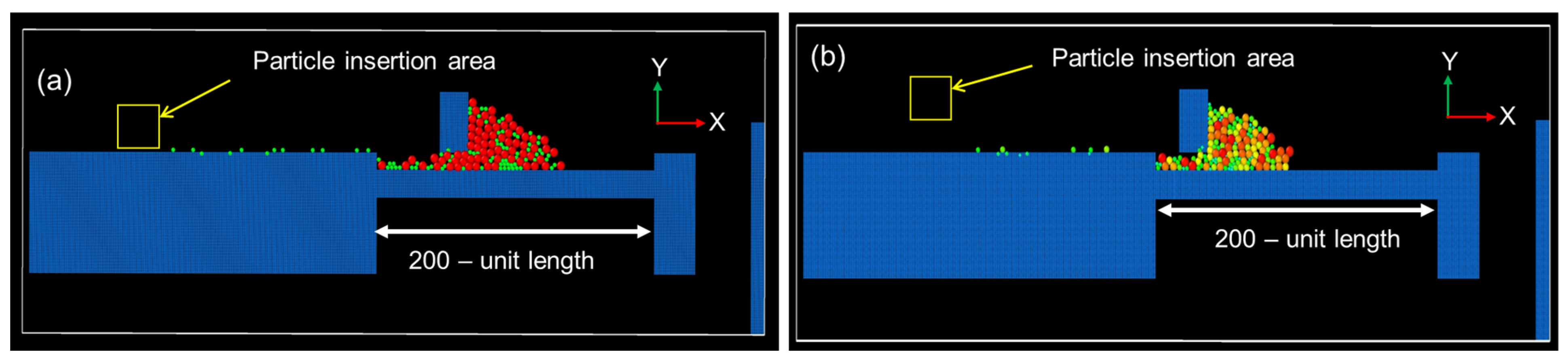
2. Methodology and Simulation Setup

Bimodal and unimodal systems were constructed using a serial version of the molecular dynamics platform LAMMPS [25]. The diameter choice for the bimodal particle distribution was D_B = 2 × D_S, where D_B and D_S are the diameters of the big particle and small particles, respectively. The particle size ratio for the bimodal mixture was adopted from this study [26]. A well-established theory in powder metallurgy depicts that a proper mixture of bimodal powders can improve the powder bed density. The optimal mixing ratio of bimodal powders also depends on some parameters like powder morphology and size distribution. Moreover, an analytical model developed by Farr and Groot [27] shows that an increase in particle size ratio affects the packing density and optimal mixing ratio. For the unimodal system, the particle diameters were set from a 2- to 6-unit scale for the calculation. A set of varied volume fractions (0.1–0.6) with different initialization velocities was introduced in the simulation. A higher volume fraction means more particles are inserted in each time step. Granular particles were poured from a certain distance (an insertion region was created spanning from 60- to 120-unit length in the x ^ -direction and 140 to 160 in the y ^ -direction), mimicking free fall from a hopper in the powder bed system as shown in Figure 1.
The ‘fix pour’ command from LAMMPS was used for pouring particles into the bed. Gravity was set at three times the natural gravity (9.8 ms−2) to adjust and minimize the excessive bouncing of the particles. As shown in Figure 2, the simulation was confined to two dimensions, but according to LAMMPS customary, the third dimension was also defined. The non-periodic boundary condition was applied to x ^ -direction (fixed) and y ^ -direction (shrink-wrapped). The z ^ -direction was applied as periodic with a narrow but finite dimension (−0.5 to 0.5 unit length). A micro-canonical ensemble NVE (constant particle, volume, and energy) was used to update the particles’ position in the powder bed. A Gran style Hertz/history command was employed to calculate the frictional force between two particles [28,29,30]. The force only works when the distance between two particles of different radii is less than the contact distance. The Hertzian style equation used in this study is shown below:
F h z = δ R i R j R i + R j F h k = δ R i R j R i + R j [ k n δ n i j m e f f γ n ν n ( k t s t + m e f f γ t ν t ) ]
where
  • δ = overlap distance between two particles;
  • k n = elastic constant for normal contact;
  • k t = elastic constant for tangential contact;
  • R i , R j = radius of two different particles;
  • γ n = viscoelastic damping constant for normal contact;
  • γ t = viscoelastic damping constant for tangential contact;
  • ν n = normal component of the relative velocity of two particles;
  • ν t = tangential component of the relative velocity of two particles;
  • s t = tangential displacement vector between two particles;
  • m e f f = effective mass of two particles with M i and M j mass;
  • n i j = unit vector that connects the centerline of two particles.
In Equation (1), the normal force and tangential force between two particles are shown in the first parenthesized term and second parenthesized term, respectively. Further details about this equation can be found in these studies [28,29,30].
For our entire simulation, we set out the basic units as m = π 6 ,   g = 3 , and d = 1 . Times, velocities, forces, distances, and elastic constants were then measured in the units of d g , g d , m g ,   d ,   m g d , respectively. The materials’ (powder particles) properties and timesteps, which are used in this simulation, are listed in Table 1.
As shown in Figure 2a the powder bed has a length of 200 unit length and after each recoating cycle, it moves downwards with a step size of 5-unit length. Lattice style square was selected to create all the powder bed components and other simulation parts. As our system is two-dimensional in nature, the z ^ -direction velocity of the particles was set to zero by the ‘fix enforce2d’ command. A frictional wall was applied in both the x ^ and y ^ directions to simulate the powder bed. Figure 1 shows the schematic of a laser powder bed fusion process. The spreading of powder over the powder bed was carried out thirteen times to observe the powder flow in the proposed simulation (shown in Figure 2). The whole bed (marked with yellow arrows in Figure 2a,b), which contains powder, was considered when calculating the packing density from a 2D image. The 2D images were then processed in Python to analyze the packing density of the powder bed. While visualization with the color in OVITO (version: 3.5.2) shows some pixel inaccuracy, we developed another MATLAB (version: R2023b) code for the powder particle visualization. The particle colors and empty spaces between particles were used to determine packing density. We have carefully extracted the edges of the particles and discovered the packing density via image analysis. The overall steps for the simulation are shown via a flowchart in Figure 3.

3. Simulation Results and Discussion

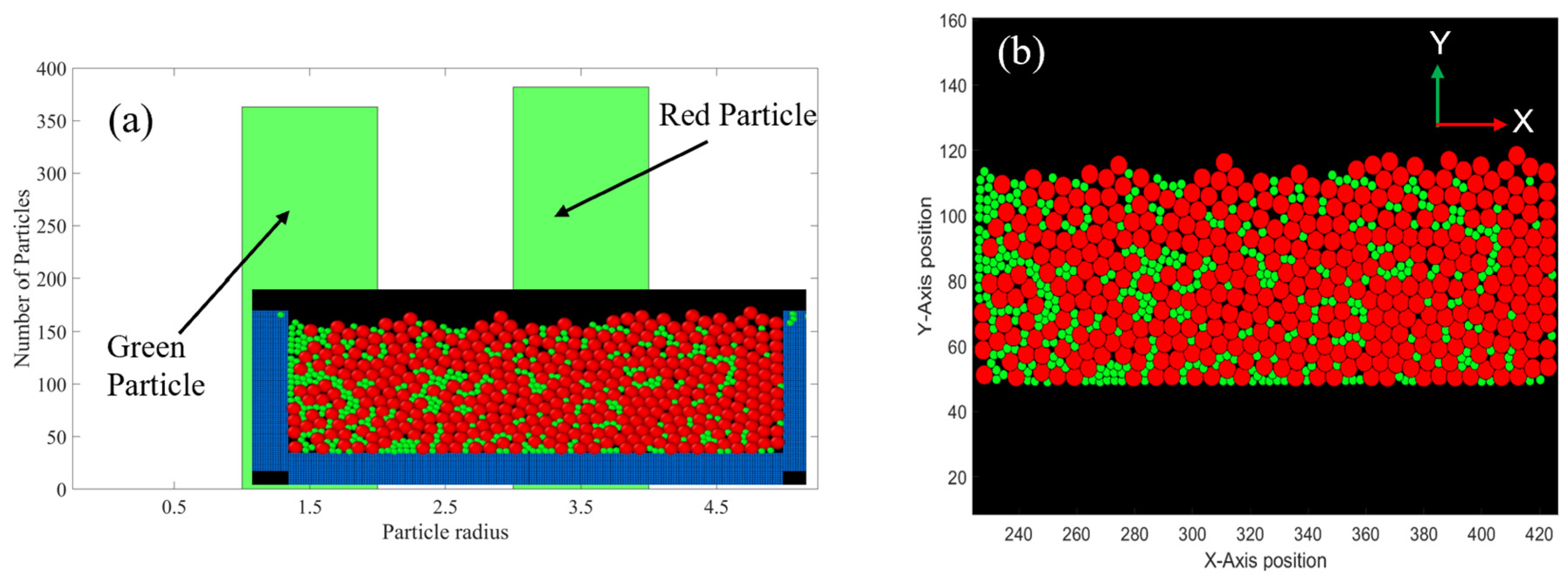
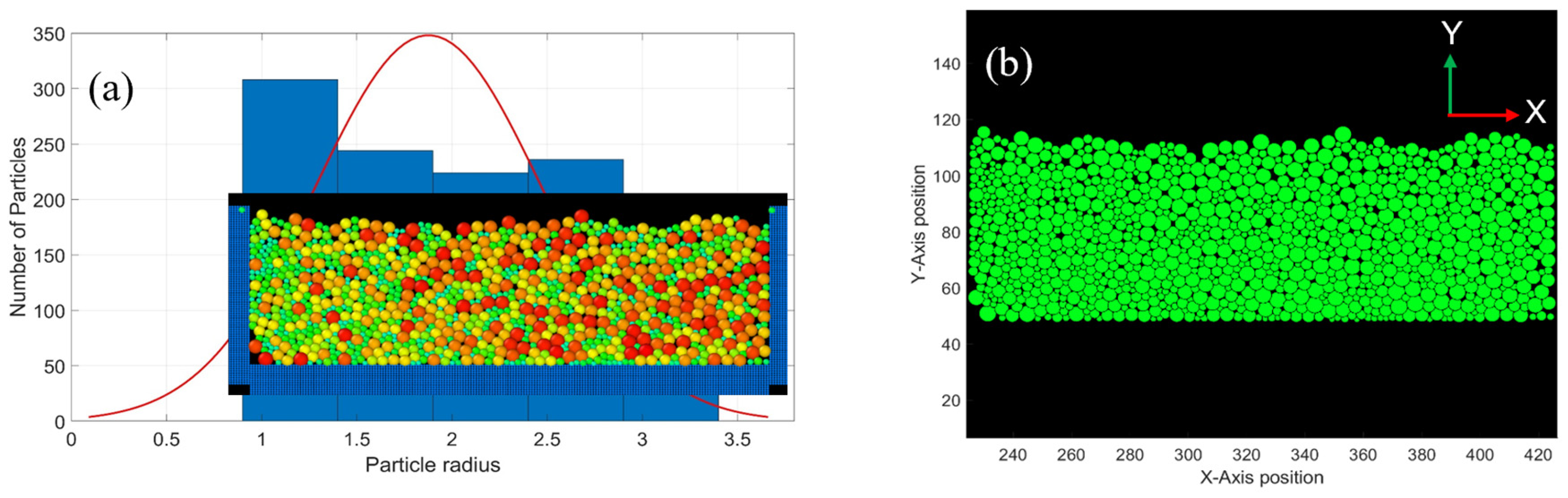
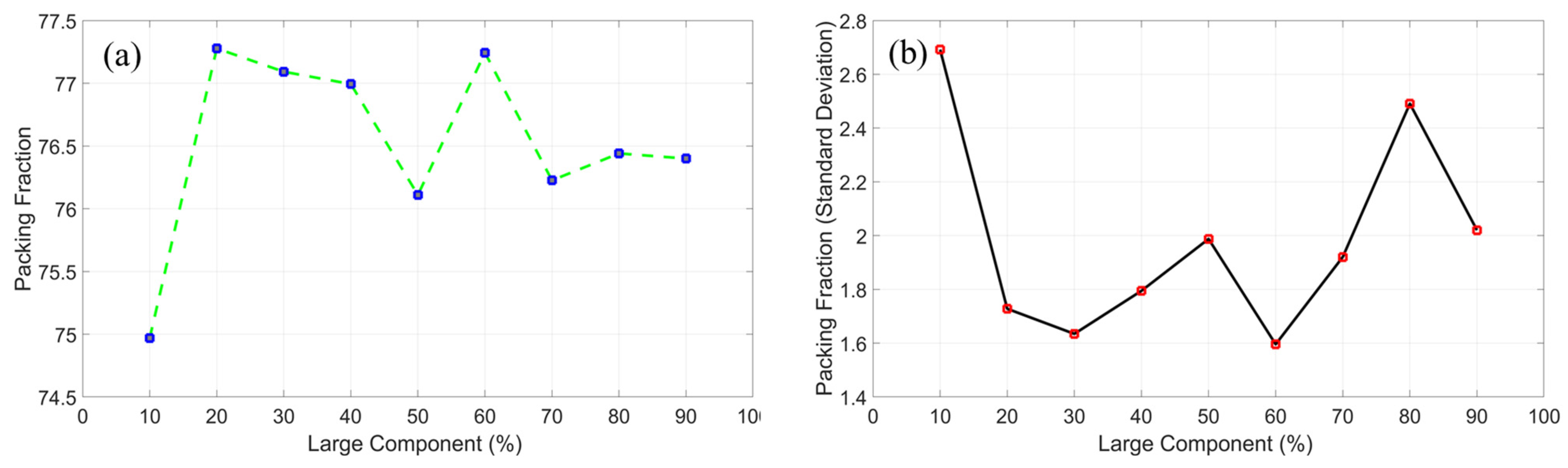
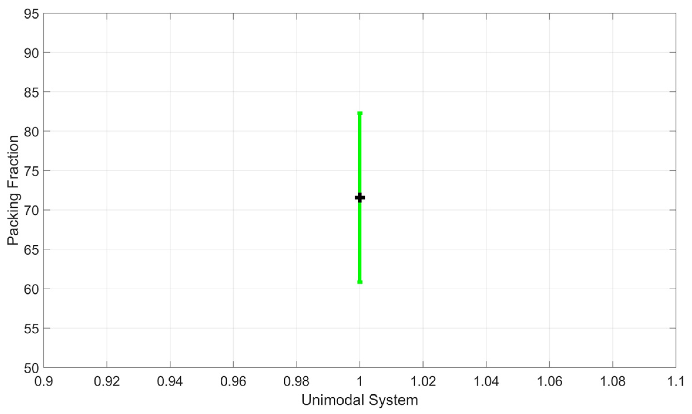
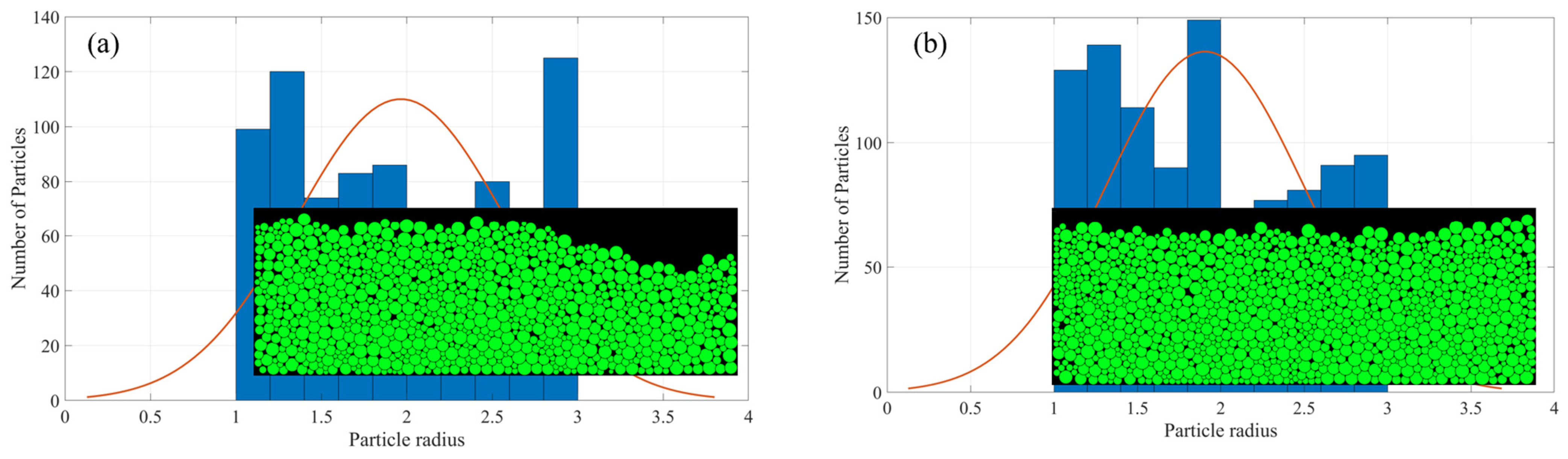
3.1. Packing Density

A bimodal powder distribution and a unimodal powder distribution are considered to see how the packing density of the powder bed varies. In the powder bed additive manufacturing process, the powder bed is expected to be compact, which means it should have a higher packing density. The packing density of the powder bed depends on how closely the powders are packed in a given volume. For simplicity, the particle shape was considered spherical because it was easy to model and calculate the interactions between particles. A bimodal (Figure 4a–c) and a unimodal system (Figure 4d) were considered in this study. Figures of the simulated powder bed model are demonstrated in Figure 5 and Figure 6. The output of the MD simulation was visualized using the Open Visualization Tool (OVITO, version: 3.5.2) [31] software.
The packing variation for the presence of big and small particles was observed for the bimodal system (Figure 7a). The presence of big particles used in the bimodal mixture ranged from 10 to 90%. When the presence of big particles was only 10%, the average packing fraction was observed to be 74.97% with a big standard deviation (Figure 7b). The packing fraction becomes as high as 78.79% when the big particle percentage is 10%, which means that the presence of smaller particles can increase the packing density of the powder bed. This process of filling the voids with smaller particles is called the filling effect [32]. From Figure 5a,b we can see that the smaller particles fall to the front portion of the bed. During the recoating process, the rack scraps all the particles, but due to the smaller size of some particles, they make their way to the first part of the bed. This creates a packing variation all over the bed. With the increase in the large particle fraction (left to right for the X-axis), the larger particles tend to replace smaller particles and fill the voids among them. This is called the occupying effect of the large particles [32]. Thus, the packing density increases to a maximum (at 60% large particle fraction), which later decreases with the increase in big particles because of the wall effect of large particles [32]. An equal percentage of the volume fraction of large and small particles leaves more void space in the system due to the counter effect of filling and occupying. A visual comparison of void for the 20% bigger particle and 80% bigger particles was displayed in Figure 8. From Figure 8a, it can be seen that the smaller particles are filling the gaps left by the bigger particles, whereas, in Figure 8b, there are some gaps between the large particles which are not filled up by the smaller ones, resulting in smaller packing. There were agglomerations observed in a certain portion of the bed (the area marked by the yellow rectangle in Figure 8a,b) which is due to the flow particles in the bed. Even though particle agglomeration was not observed for particles with similar materials (powder particles), we can naturally see agglomeration in ceramics and metal alloys because of the inter-particle forces (e.g., van der Waals force) and improper production parameters [33,34].
A defined range (the ‘range’ is mentioned in the methodology and setup section) of particles was poured on the powder bed for the unimodal system. The packing observed for the unimodal system is shown in Figure 9. The packing fraction average varied with a big standard deviation for the unimodal system. We see this variation because of the variable volume of powder poured into the bed.
At the lower volume fraction (0.1) of powder pouring onto the bed from the feeder, there are fewer particles in the bed (Figure 10a). However, an increase in packing was observed in the higher volume fraction (0.6) pouring of powders. The packing for both the unimodal and the bimodal systems varied between 70% and 83% in our simulation. Researchers [35] studied the packing for a 2D system in confinement, with a confining width h ranging from three to thirty. They used the unit of h as a non-dimensional form which is nondimensionalized by the diameter of small particles. The packing fraction was varied between 0.72 and 0.83 for the finite confinement (h), but when the value of confinement (h) tends to infinity, the packing fraction becomes 0.842. So, our results show a good agreement with the study authored by Desmond et al. [35].

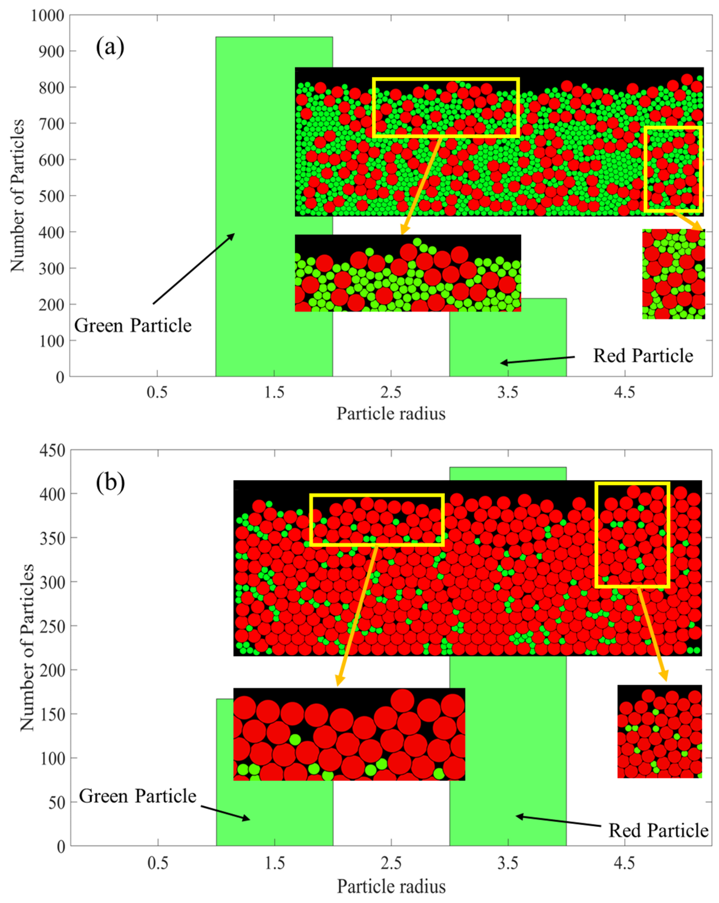
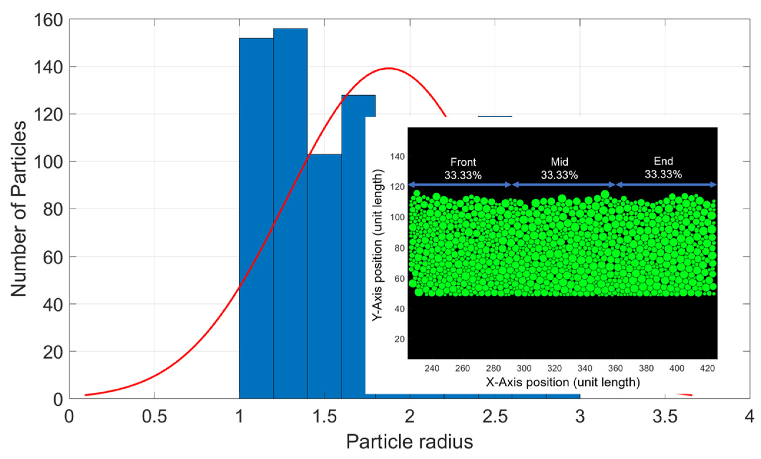
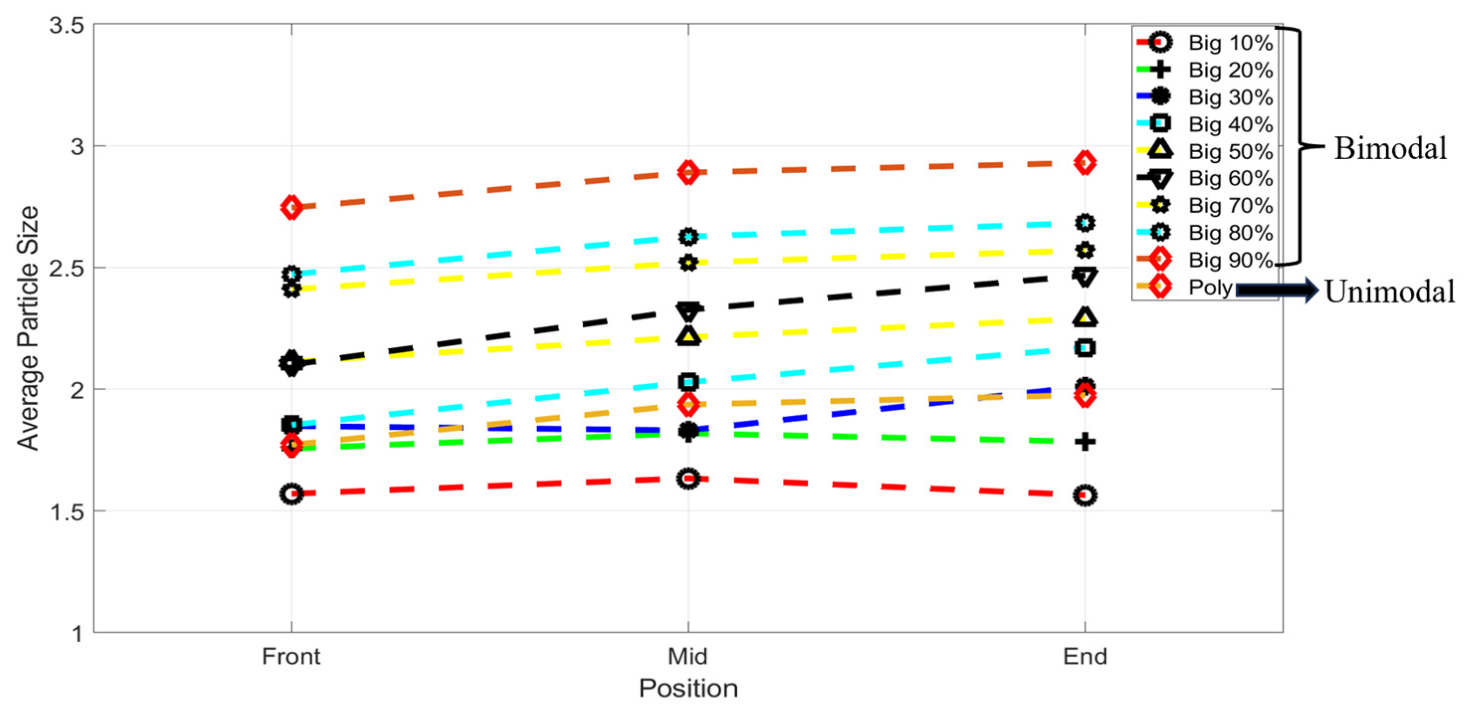
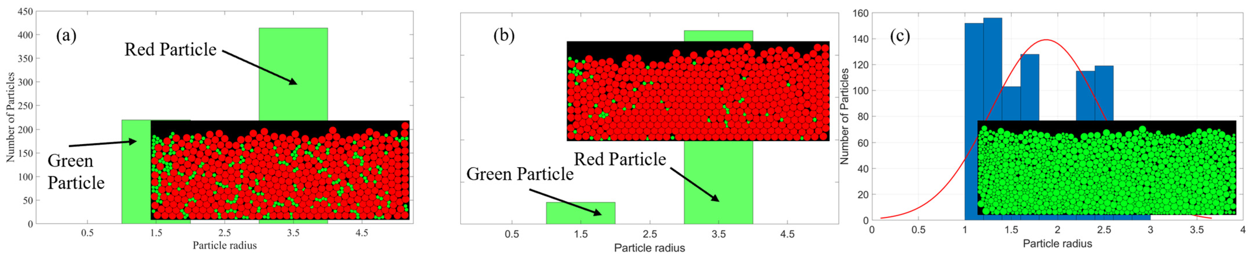
3.2. Powder Segregation

In order to characterize the uniformity of powder layers, we also investigated the powder segregation processes. Particle segregation is assumed to occur for various reasons, such as recoater velocity, particle size distribution, and concentration of fine particles [36,37]. The powder segregation process was measured across three portions of the bed. The first 33.33% of the bed was considered the front, the next 33.33% was the middle, and the rest was the end of the bed (Figure 11). Figure 12 shows that smaller particles were deposited at the front part of the bed. For the bimodal mixture, when the bigger particle percentage was between 10 and 60%, we can see more segregation of the powders in the bed. Because of the segregation, we can see the uneven uniformity in different portions of the bed.
When the bigger particle percentage was 70–90%, the segregation was observed to improve towards the far end of the bed as shown in Figure 13a,b. That means the powder bed is nearly uniform from the middle of the bed to the end. We also observed the percolation effect in the powder bed. The percolation effect is a dynamic sieving for which the powder particles pass through any temporary voids in the powder bed [38,39]. Because of the percolation effect, the bimodal powder distribution demonstrated significant power segregation in the powder bed. A research study [40] showed that segregation happens because the bigger particles are most likely carried by the powder racks. Other researchers also reported similar types of effects from their experiment [41]. However, for the unimodal system, the segregation substantially improved after the middle portion of the bed, as shown in Figure 13c. Figure 13c shows the unimodal system, in which we can see particle uniformity on the middle and end portions of the powder bed. During the segregation process, while the small particles try to fill up the spaces between large particles, the large particles move up, due to the shear force [42]. The bimodal particles showed more segregation than the unimodal particles. This type of segregation trend for bimodal and unimodal powder was also observed in a set of experiments performed by Haferkamp et al. [43].
The use of bimodal powders has been a growing area of interest in powder bed AM because of their aforementioned attributes. With limited research available on this topic, the authors believe this study will advance knowledge of how these particles behave when used in powder bed AM. Further studies on bimodal power particles including experimental validation that involves real-time imaging presented by Priyadarshi et al. [44] will enhance our understanding of these powders.

4. Conclusions

In summary, we successfully developed a powder bed system and modeled power spreading. We defined the parameters and analyzed how those parameters characterize packing fractions for poly-disperse (non-uniform) particles. Bimodal and unimodal systems were employed to study the surface morphology and behavior of a powder bed. The bimodal particle system showed a higher packing fraction than the unimodal system. So, a proper bimodal powder mixture with a varying particle size ratio can be considered for future study. Particle segregation was observed for both the bimodal and unimodal systems. The bimodal mixture has a dominant percolation effect which ultimately results in powder segregation. By changing the particle size ratio, the percolation effect may be minimized. It was observed that the large particles in the bimodal system were carried further away by the powder rack.
The two-dimensional molecular dynamics model was useful to understand particle behavior in the powder bed, which is also computationally inexpensive. The proposed model can be applied to different materials, such as stainless steel, nickel, copper, etc., by varying the powder properties in the model. While in this study only spherical particles were considered, it can be further extended to include non-spherical particles to simulate a more realistic situation. Since packing fraction plays a critical role in powder bed systems, this study offers a cost-effective means to study the characteristics of powders and predict build quality in powder bed additive manufacturing processes.

Author Contributions

Conceptualization, Y.M.A., E.M. and F.A.; methodology, Y.M.A., E.M. and F.A.; software, Y.M.A.; validation, Y.M.A., E.M. and F.A.; formal analysis, Y.M.A.; investigation, Y.M.A.; resources, F.A.; data curation, Y.M.A.; writing—original draft preparation, Y.M.A.; writing—review and editing, Y.M.A., E.M. and F.A.; visualization, Y.M.A.; supervision, E.M. and F.A.; project administration, E.M. and F.A. All authors have read and agreed to the published version of the manuscript.

Funding

This research received no external funding.

Data Availability Statement

The authors confirm that the analyzed data that support the findings of this study are available within the article and others are available upon request.

Conflicts of Interest

The authors declare that they have no known competing financial interests or personal relationships that could have appeared to influence the work reported in this study.

References

  1. Buchbinder, D.; Schleifenbaum, H.; Heidrich, S.; Meiners, W.; Bültmann, J. High Power Selective Laser Melting (HP SLM) of Aluminum Parts. Phys. Procedia 2011, 12, 271–278. [Google Scholar] [CrossRef]
  2. Santos, E.C.; Shiomi, M.; Osakada, K.; Laoui, T. Rapid manufacturing of metal components by laser forming. Int. J. Mach. Tools Manuf. 2006, 46, 1459–1468. [Google Scholar] [CrossRef]
  3. Young, Z.; Qu, M.; Coday, M.M.; Guo, Q.; Hojjatzadeh, S.M.H.; Escano, L.I.; Fezzaa, K.; Chen, L. Effects of particle size distribution with efficient packing on powder flowability and selective laser melting process. Materials 2022, 15, 705. [Google Scholar] [CrossRef] [PubMed]
  4. Gibson, I.; Rosen, D.W.; Stucker, B.; Khorasani, M.; Rosen, D.; Stucker, B.; Khorasani, M. Additive Manufacturing Technologies; Springer: Cham, Switzerland, 2021; Volume 17. [Google Scholar]
  5. Gregorski, S.J. High Green Density Metal Parts by Vibrational Compaction of Dry Powder in the Three-Dimensional Printing Process. Ph.D. Thesis, Massachusetts Institute of Technology, Cambridge, MA, USA, 2003. [Google Scholar]
  6. Gu, D.; Shen, Y. Balling phenomena in direct laser sintering of stainless steel powder: Metallurgical mechanisms and control methods. Mater. Des. 2009, 30, 2903–2910. [Google Scholar] [CrossRef]
  7. Qiu, Y.-D.; Wu, J.-M.; Chen, A.-N.; Chen, P.; Yang, Y.; Liu, R.-Z.; Chen, G.; Chen, S.; Shi, Y.-S.; Li, C.-H. Balling phenomenon and cracks in alumina ceramics prepared by direct selective laser melting assisted with pressure treatment. Ceram. Int. 2020, 46, 13854–13861. [Google Scholar] [CrossRef]
  8. Xiang, Z.; Yin, M.; Deng, Z.; Mei, X.; Yin, G. Simulation of forming process of powder bed for additive manufacturing. J. Manuf. Sci. Eng. 2016, 138, 081002. [Google Scholar] [CrossRef]
  9. Zhou, J.; Zhang, Y.; Chen, J.K. Numerical simulation of random packing of spherical particles for powder-based additive manufacturing. J. Manuf. Sci. Eng. 2009, 131, 031004. [Google Scholar] [CrossRef]
  10. Coe, H.G.; Pasebani, S. Use of bimodal particle size distribution in selective laser melting of 316L stainless steel. J. Manuf. Mater. Process. 2020, 4, 8. [Google Scholar] [CrossRef]
  11. Vermeer, P.A.; Diebels, S.; Ehlers, W.; Herrmann, H.J.; Luding, S.; Ramm, E. Continuous and Discontinuous Modelling of Cohesive-Frictional Materials; Springer Science & Business Media: Berlin/Heidelberg, Germany, 2001; Volume 568. [Google Scholar]
  12. Cheung, S.L.; Chua, C.K.; Zhou, K.; Wei, J. Effects of temperature on particle coalescence in the selective laser sintering process. In Proceedings of the 1st International Conference on Progress in Additive Manufacturing (Pro-AM 2014), Singapore, 26–28 May 2014. [Google Scholar]
  13. Herrmann, H.J. Molecular dynamics simulations of granular materials. Int. J. Mod. Phys. C 1993, 4, 309–316. [Google Scholar] [CrossRef]
  14. Li, S.; Yao, Q.; Chen, B.; Zhang, X.; Ding, Y. Molecular dynamics simulation and continuum modelling of granular surface flow in rotating drums. Chin. Sci. Bull. 2007, 52, 692–700. [Google Scholar] [CrossRef]
  15. Averardi, A.; Cola, C.; Zeltmann, S.E.; Gupta, N. Effect of particle size distribution on the packing of powder beds: A critical discussion relevant to additive manufacturing. Mater. Today Commun. 2020, 24, 100964. [Google Scholar] [CrossRef]
  16. Cao, L. Numerical simulation of the impact of laying powder on selective laser melting single-pass formation. Int. J. Heat Mass Transf. 2019, 141, 1036–1048. [Google Scholar] [CrossRef]
  17. Fouda, Y.M.; Bayly, A.E. A DEM study of powder spreading in additive layer manufacturing. Granul. Matter 2019, 22, 10. [Google Scholar] [CrossRef]
  18. Lee, Y.S.; Nandwana, P.; Zhang, W. Dynamic simulation of powder packing structure for powder bed additive manufacturing. Int. J. Adv. Manuf. Technol. 2018, 96, 1507–1520. [Google Scholar] [CrossRef]
  19. Ganeriwala, R.; Zohdi, T.I. A coupled discrete element-finite difference model of selective laser sintering. Granul. Matter 2016, 18, 21. [Google Scholar] [CrossRef]
  20. Markl, M.; Körner, C. Powder layer deposition algorithm for additive manufacturing simulations. Powder Technol. 2018, 330, 125–136. [Google Scholar] [CrossRef]
  21. Farzadfar, S.A.; Murtagh, M.J.; Venugopal, N. Impact of IN718 bimodal powder size distribution on the performance and productivity of laser powder bed fusion additive manufacturing process. Powder Technol. 2020, 375, 60–80. [Google Scholar] [CrossRef]
  22. Yang, W.; Cai, Z.; Duan, W.; Deng, X.; Lin, T.; Chen, Z.; Xie, F.; Liu, J.; Qu, Z.; Jin, F. Effect of feedstock bimodal powder design and cold isostatic pressing on the mechanical behavior of binder jetting additive manufactured Inconel 718 superalloy. J. Manuf. Process. 2025, 133, 607–622. [Google Scholar] [CrossRef]
  23. Clares, A.P.; Gao, Y.; Stebbins, R.; van Duin, A.C.; Manogharan, G. Increasing density and mechanical performance of binder jetting processing through bimodal particle size distribution. Mater. Sci. Addit. Manuf. 2022, 1, 20. [Google Scholar] [CrossRef]
  24. LAMMPS. Granular Pouring and Chute Flow. Available online: https://www.lammps.org/movies.html (accessed on 7 January 2024).
  25. Thompson, A.P.; Aktulga, H.M.; Berger, R.; Bolintineanu, D.S.; Brown, W.M.; Crozier, P.S.; in’t Veld, P.J.; Kohlmeyer, A.; Moore, S.G.; Nguyen, T.D. LAMMPS-a flexible simulation tool for particle-based materials modeling at the atomic, meso, and continuum scales. Comput. Phys. Commun. 2022, 271, 108171. [Google Scholar] [CrossRef]
  26. Du, W.; Roa, J.; Hong, J.; Liu, Y.; Pei, Z.; Ma, C. Binder jetting additive manufacturing: Effect of particle size distribution on density. J. Manuf. Sci. Eng. 2021, 143, 091002. [Google Scholar] [CrossRef]
  27. Farr, R.S.; Groot, R.D. Close packing density of polydisperse hard spheres. J. Chem. Phys. 2009, 131, 244104. [Google Scholar] [CrossRef] [PubMed]
  28. Brilliantov, N.V.; Spahn, F.; Hertzsch, J.-M.; Pöschel, T. Model for collisions in granular gases. Phys. Rev. E 1996, 53, 5382. [Google Scholar] [CrossRef] [PubMed]
  29. Silbert, L.E.; Ertaş, D.; Grest, G.S.; Halsey, T.C.; Levine, D.; Plimpton, S.J. Granular flow down an inclined plane: Bagnold scaling and rheology. Phys. Rev. E 2001, 64, 051302. [Google Scholar] [CrossRef] [PubMed]
  30. Zhang, H.P.; Makse, H.A. Jamming transition in emulsions and granular materials. Phys. Rev. E 2005, 72, 011301. [Google Scholar] [CrossRef]
  31. Stukowski, A. Visualization and analysis of atomistic simulation data with OVITO–the Open Visualization Tool. Model. Simul. Mater. Sci. Eng. 2009, 18, 015012. [Google Scholar] [CrossRef]
  32. Stovall, T.; De Larrard, F.; Buil, M. Linear packing density model of grain mixtures. Powder Technol. 1986, 48, 1–12. [Google Scholar] [CrossRef]
  33. Chu, F.; Zhang, K.; Shen, H.; Liu, M.; Huang, W.; Zhang, X.; Liang, E.; Zhou, Z.; Lei, L.; Hou, J. Influence of satellite and agglomeration of powder on the processability of AlSi10Mg powder in Laser Powder Bed Fusion. J. Mater. Res. Technol. 2021, 11, 2059–2073. [Google Scholar] [CrossRef]
  34. Liu, M.; Chiu, L.N.S.; Shen, H.; Fang, X.; Tao, Z.; Huang, A.; Davies, C.; Wu, X.; Yan, W. Effective thermal conductivities of metal powders for additive manufacturing. Powder Technol. 2022, 401, 117323. [Google Scholar] [CrossRef]
  35. Desmond, K.W.; Weeks, E.R. Random close packing of disks and spheres in confined geometries. Phys. Rev. E 2009, 80, 051305. [Google Scholar] [CrossRef]
  36. Tang, P.; Puri, V.M. Methods for minimizing segregation: A review. Part. Sci. Technol. 2004, 22, 321–337. [Google Scholar] [CrossRef]
  37. Nan, W.; Pasha, M.; Ghadiri, M. Numerical simulation of particle flow and segregation during roller spreading process in additive manufacturing. Powder Technol. 2020, 364, 811–821. [Google Scholar] [CrossRef]
  38. Arntz, M.; Beeftink, H.H.; den Otter, W.K.; Briels, W.J.; Boom, R.M. Segregation of granular particles by mass, radius, and density in a horizontal rotating drum. AIChE J. 2014, 60, 50–59. [Google Scholar] [CrossRef]
  39. Jha, A.K.; Puri, V.M. Percolation segregation of multi-size and multi-component particulate materials. Powder Technol. 2010, 197, 274–282. [Google Scholar] [CrossRef]
  40. Mindt, H.; Megahed, M.; Lavery, N.; Holmes, M.; Brown, S. Powder bed layer characteristics: The overseen first-order process input. Metall. Mater. Trans. A 2016, 47, 3811–3822. [Google Scholar] [CrossRef]
  41. Whiting, J.; Fox, J. Characterization of Feedstock in the Powder Bed Fusion Process: Sources of Variation in Particle Size Distribution and the Factors That Influence Them; The University of Texas at Austin: Austin, TX, USA, 2016. [Google Scholar]
  42. Tennakoon, S.; Kondic, L.; Behringer, R. Onset of flow in a horizontally vibrated granular bed: Convection by horizontal shearing. Europhys. Lett. 1999, 45, 470. [Google Scholar] [CrossRef]
  43. Haferkamp, L.; Liechti, S.; Spierings, A.; Wegener, K. Effect of bimodal powder blends on part density and melt pool fluctuation in laser powder bed fusion. Prog. Addit. Manuf. 2021, 6, 407–416. [Google Scholar] [CrossRef]
  44. Priyadarshi, A.; Shahrani, S.B.; Choma, T.; Zrodowski, L.; Qin, L.; Leung, C.L.A.; Clark, S.J.; Fezzaa, K.; Mi, J.; Lee, P.D. New insights into the mechanism of ultrasonic atomization for the production of metal powders in additive manufacturing. Addit. Manuf. 2024, 83, 104033. [Google Scholar] [CrossRef]
Figure 1. Schematic figure of a laser powder bed fusion process.
Jmmp 09 00009 g001
Figure 2. Snapshot of the powder bed platform constructed using the granular module of LAMMPS: (a) unimodal distribution; (b) bimodal distribution.
Jmmp 09 00009 g002
Figure 3. Flowchart of the MD simulation.
Jmmp 09 00009 g003
Figure 4. Bimodal mixture for (a) 10% larger particles, (b) 50% larger particles, (c) 90% larger particles; (d) unimodal mixture.
Jmmp 09 00009 g004
Figure 5. (a) Bimodal powders on the powder bed (LAMMPS output); (b) MATLAB visualization of powders for the bimodal mixture.
Jmmp 09 00009 g005
Figure 6. (a) Unimodal powders on the powder bed (LAMMPS output); (b) MATLAB visualization of powders for the unimodal mixture.
Jmmp 09 00009 g006
Figure 7. (a) Packing fraction calculations for bimodal system; (b) standard deviation of packing of bimodal system.
Jmmp 09 00009 g007
Figure 8. Powder bed condition for bimodal mixture: (a) 20% bigger particles; (b) 80% bigger particles.
Jmmp 09 00009 g008
Figure 9. Packing fraction calculations for the unimodal system.
Jmmp 09 00009 g009
Figure 10. Powder bed condition (unimodal system) (a) lower volume fraction and (b) higher volume fraction.
Jmmp 09 00009 g010
Figure 11. Powder bed segment used for calculating the segregation.
Jmmp 09 00009 g011
Figure 12. Powder bed morphology for the bimodal and unimodal mixture.
Jmmp 09 00009 g012
Figure 13. Powder bed morphology: (a,b) bimodal system, and (c) unimodal system.
Jmmp 09 00009 g013
Table 1. Pair style properties for simulation.
Distribution k n k t / k n γ n γ t / γ n t
Bimodal 4000 2 / 7 350 1 / 2 0.001
Unimodal 4000 2 / 7 350 1 / 2 0.001
Disclaimer/Publisher’s Note: The statements, opinions and data contained in all publications are solely those of the individual author(s) and contributor(s) and not of MDPI and/or the editor(s). MDPI and/or the editor(s) disclaim responsibility for any injury to people or property resulting from any ideas, methods, instructions or products referred to in the content.

