
Fast-Response Liquid Crystals for 6G Optical Communications


Abstract
:
1. Introduction
2. Material Characterizations
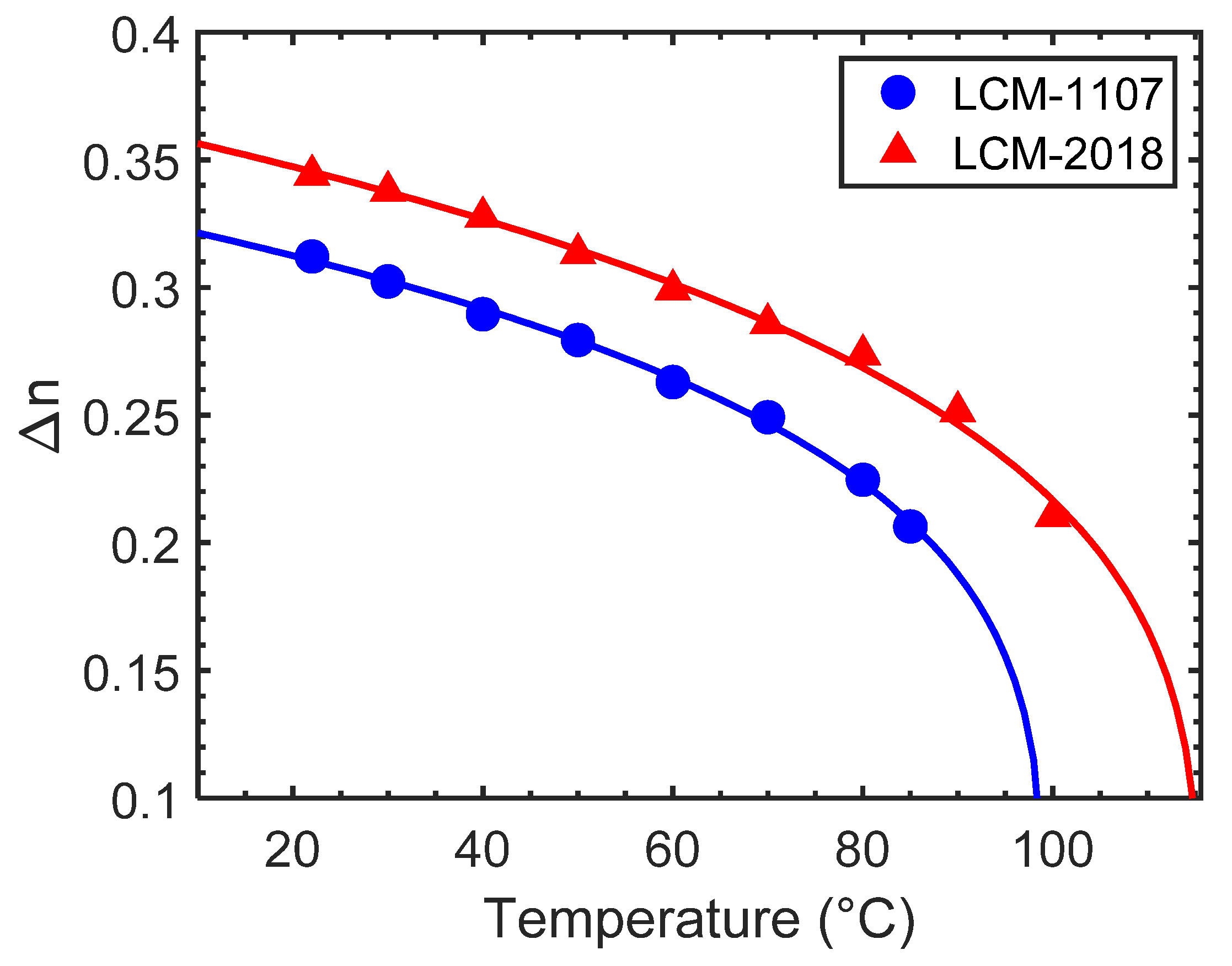
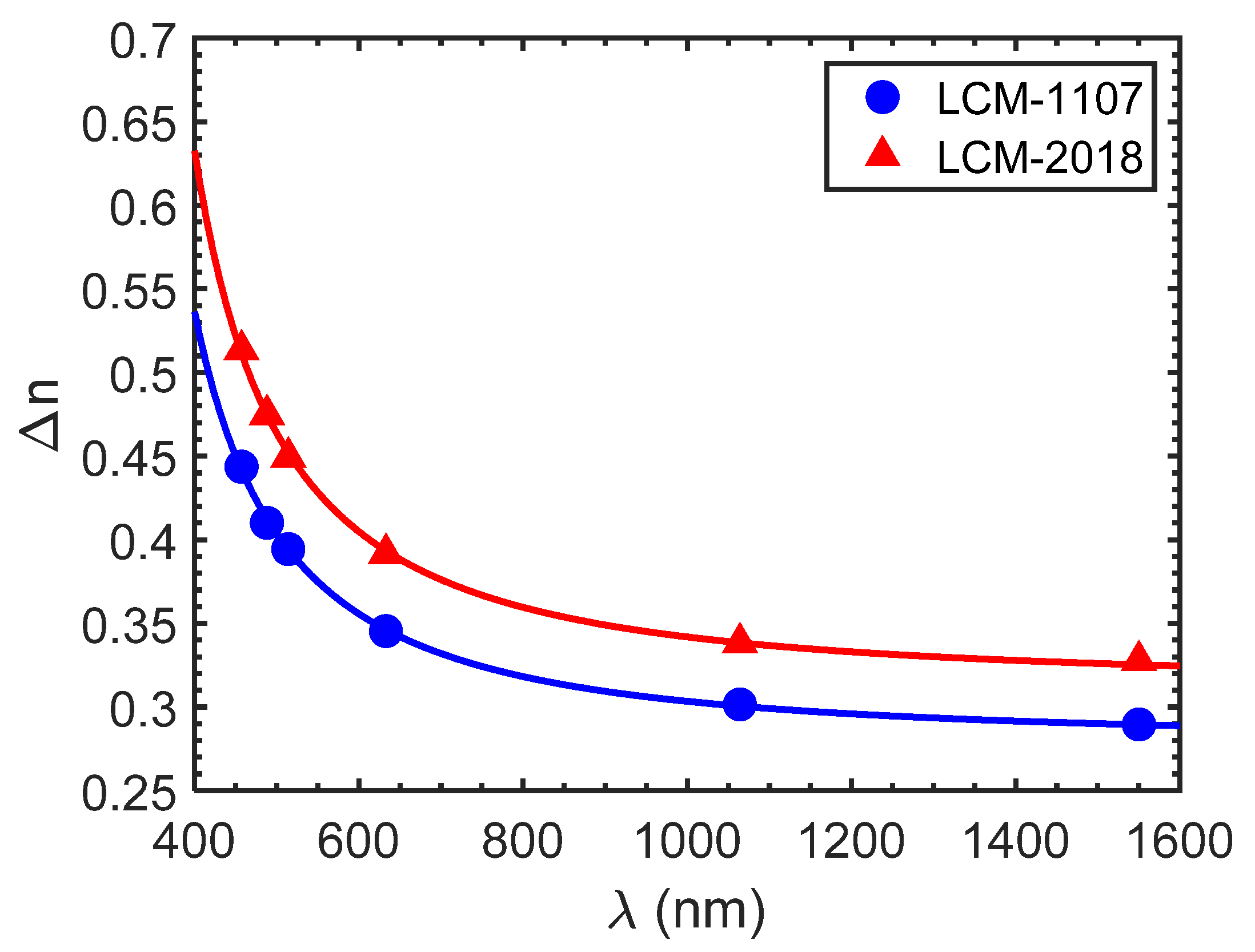
2.1. Birefringence
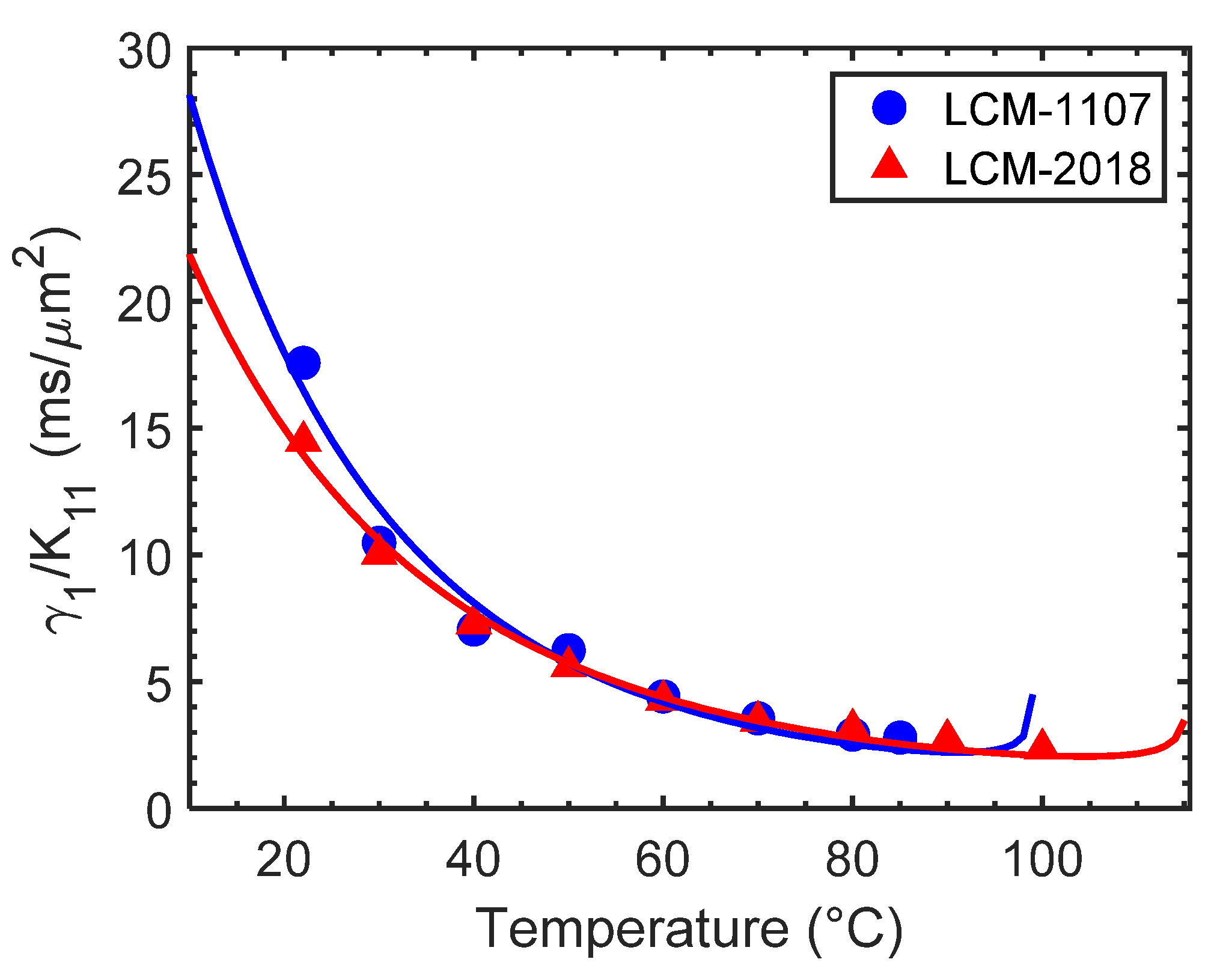
2.2. Viscoelastic Constant
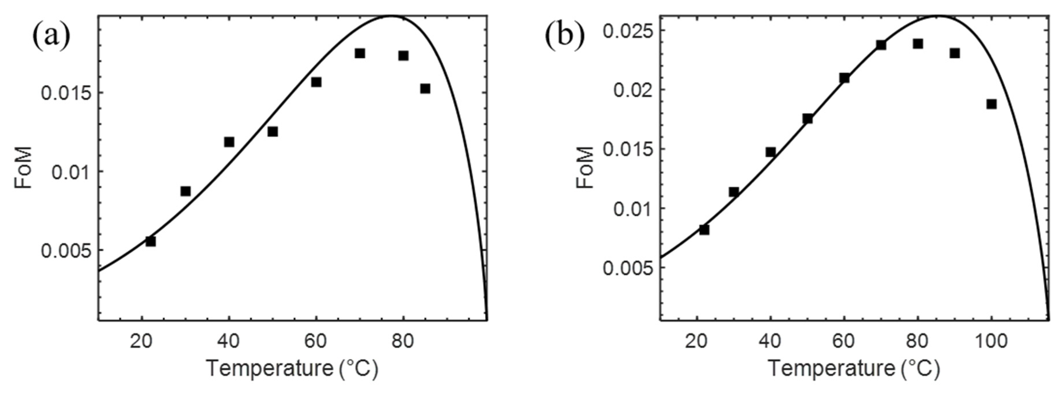
2.3. Figure of Merit
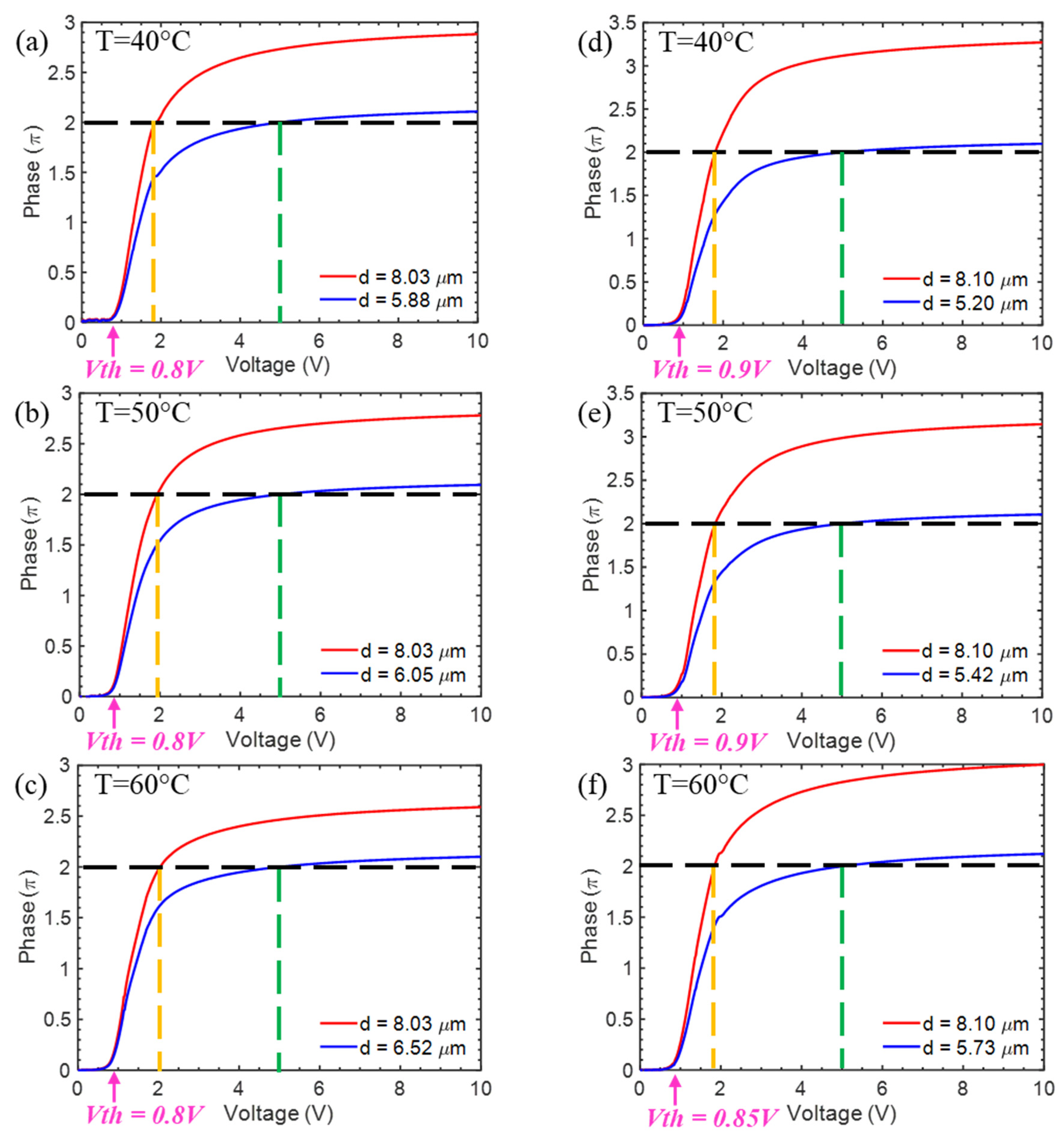
2.4. Voltage-Dependent Phase Change
2.5. Response Time
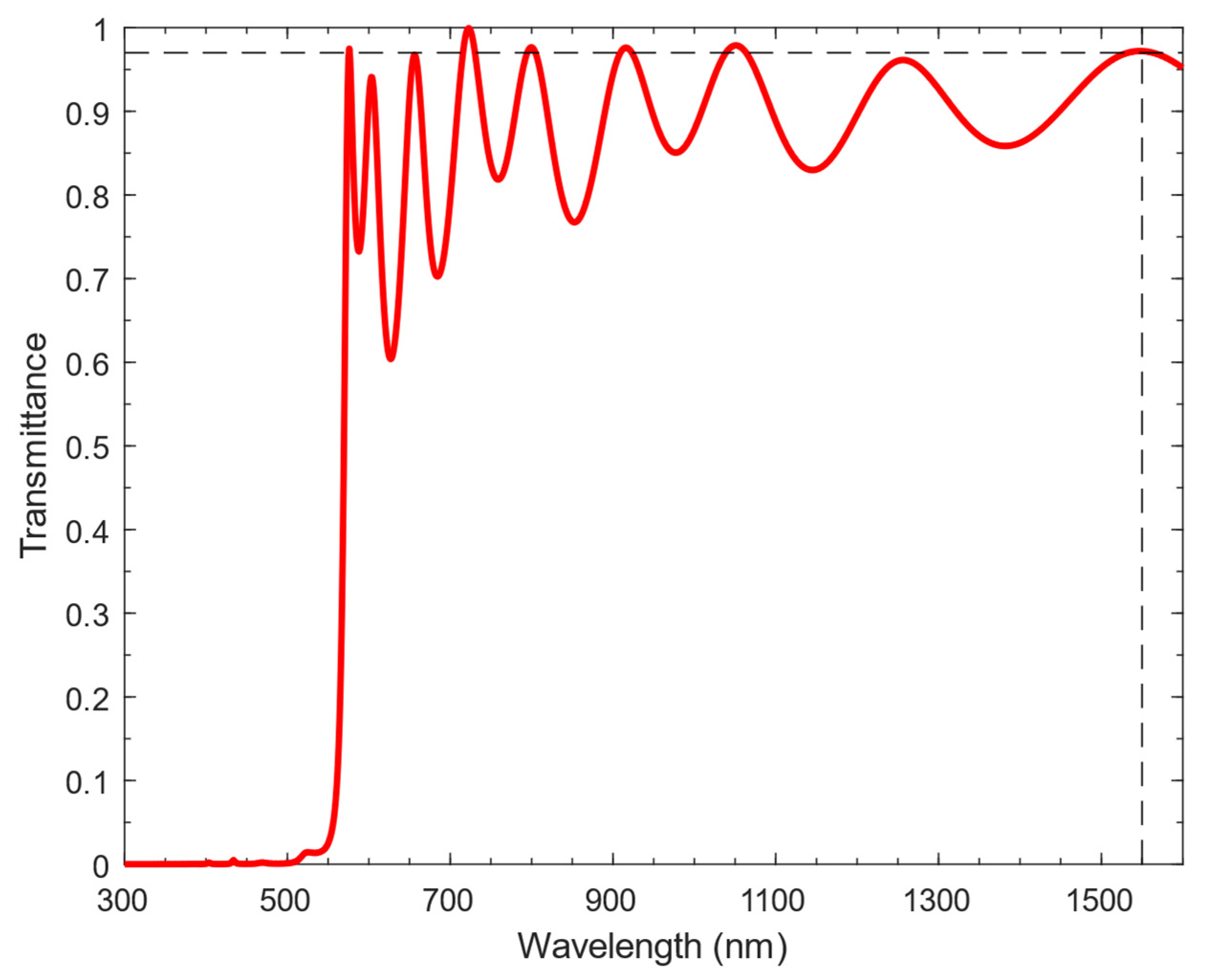
3. Coating Design
4. Conclusions
Author Contributions
Funding
Acknowledgments
Conflicts of Interest
References
- Brackett, C.A. Dense wavelength division multiplexing networks: Principles and applications. IEEE J. Sel. Areas Commun. 1990, 8, 948–964. [Google Scholar] [CrossRef]
- Zhu, L.; Zhu, G.; Wang, A.; Wang, L.; Ai, J.; Chen, S.; Du, C.; Liu, J.; Yu, S.; Wang, J. 18 km low-crosstalk OAM+ WDM transmission with 224 individual channels enabled by a ring-core fiber with large high-order mode group separation. Opt. Lett. 2018, 43, 1890–1893. [Google Scholar] [CrossRef] [PubMed]
- Panwar, N.; Sharma, S.; Singh, A.K. A survey on 5G: The next generation of mobile communication. Phys. Commun. 2016, 18, 64–84. [Google Scholar] [CrossRef] [Green Version]
- Giordani, M.; Polese, M.; Mezzavilla, M.; Rangan, S.; Zorzi, M. Toward 6G networks: Use cases and technologies. IEEE Commun. Mag. 2020, 58, 55–61. [Google Scholar] [CrossRef]
- Chowdhury, M.Z.; Shahjalal, M.; Ahmed, S.; Jang, Y.M. 6G wireless communication systems: Applications, requirements, technologies, challenges, and research directions. IEEE Open J. Commun. Soc. 2020, 1, 957–975. [Google Scholar] [CrossRef]
- Tibuleac, S.; Filer, M. Transmission impairments in DWDM networks with reconfigurable optical add-drop multiplexers. J. Lightwave Technol. 2010, 28, 557–568. [Google Scholar] [CrossRef]
- Wang, S.; Feng, X.; Gao, S.; Shi, Y.; Dai, T.; Yu, H.; Tsang, H.K.; Dai, D. On-chip reconfigurable optical add-drop multiplexer for hybrid wavelength/mode-division-multiplexing systems. Opt. Lett. 2017, 42, 2802–2805. [Google Scholar] [CrossRef]
- Geng, M.; Jia, L.; Zhang, L.; Yang, L.; Chen, P.; Wang, T.; Liu, Y. Four-channel reconfigurable optical add-drop multiplexer based on photonic wire waveguide. Opt. Express 2009, 17, 5502–5516. [Google Scholar] [CrossRef]
- Ma, Y.; Stewart, L.; Armstrong, J.; Clarke, I.; Baxter, G.W. Recent Progress of Wavelength Selective Switch. J. Lightwave Technol. 2020, 39, 896–903. [Google Scholar] [CrossRef]
- Marom, D.M.; Neilson, D.T.; Greywall, D.S.; Pai, C.S.; Basavanhally, N.R.; Aksyuk, V.A.; López, D.O.; Pardo, F.; Simon, M.E.; Low, Y.; et al. Wavelength-selective 1 x K switches using free-space optics and MEMS micromirrors: Theory, design, and implementation. J. Lightwave Technol. 2005, 23, 1620–1630. [Google Scholar] [CrossRef]
- Scherger, B.; Reuter, M.; Scheller, M.; Altmann, K.; Vieweg, N.; Dabrowski, R.; Deibel, J.A.; Koch, M. Discrete terahertz beam steering with an electrically controlled liquid crystal device. J. InfraredMillim. Terahertz Waves 2012, 33, 1117–1122. [Google Scholar] [CrossRef]
- Baxter, G.; Frisken, S.; Abakoumov, D.; Zhou, H.; Clarke, I.; Bartos, A.; Poole, S. Highly programmable wavelength selective switch based on liquid crystal on silicon switching elements. In Proceedings of the 2006 Optical Fiber Communication Conference and the National Fiber Optic Engineers Conference, Anaheim, CA, USA, 5–10 March 2006. [Google Scholar]
- Wang, M.; Zong, L.; Mao, L.; Marquez, A.; Ye, Y.; Zhao, H.; Vaquero, C.F.J. LCoS SLM study and its application in wavelength selective switch. Photonics 2017, 4, 22. [Google Scholar] [CrossRef] [Green Version]
- Frisken, S.; Baxter, G.; Abakoumov, D.; Zhou, H.; Clarke, I.; Poole, S. Flexible and grid-less wavelength selective switch using LCOS technology. In Proceedings of the 2011 Optical Fiber Communication Conference and Exposition and the National Fiber Optic Engineers Conference, Los Angeles, CA, USA, 6–10 March 2011. [Google Scholar]
- Zou, J.; Yang, Q.; Hsiang, E.L.; Ooishi, H.; Yang, Z.; Yoshidaya, K.; Wu, S.T. Fast-response liquid crystal for spatial light modulator and LiDAR applications. Crystals 2021, 11, 93. [Google Scholar] [CrossRef]
- Lazarev, G.; Chen, P.J.; Strauss, J.; Fontaine, N.; Forbes, A. Beyond the display: Phase-only liquid crystal on Silicon devices and their applications in photonics. Opt. Express 2019, 27, 16206–16249. [Google Scholar] [CrossRef]
- Huang, Y.; He, Z.; Wu, S.T. Fast-response liquid crystal phase modulators for augmented reality displays. Opt. Express 2017, 25, 32757–32766. [Google Scholar] [CrossRef] [Green Version]
- Yang, Q.; Zou, J.; Li, Y.; Wu, S.T. Fast-response liquid crystal phase modulators with an excellent photostability. Crystals 2020, 10, 765. [Google Scholar] [CrossRef]
- He, Z.; Yin, K.; Wu, S.T. Miniature planar telescopes for efficient, wide-angle, high-precision beam steering. Light Sci. Appl. 2021, 10, 134. [Google Scholar] [CrossRef] [PubMed]
- Wu, S.T.; Wu, C.S. Rotational viscosity of nematic liquid crystals a critical examination of existing models. Liq. Cryst. 1990, 8, 171–182. [Google Scholar] [CrossRef]
- Dąbrowski, R.; Kula, P.; Herman, J. High Birefringence Liquid Crystals. Crystals 2013, 3, 443–482. [Google Scholar] [CrossRef]
- Wu, S.T.; Efron, U.; Hess, L.D. Birefringence measurements of liquid crystals. Appl. Opt. 1984, 23, 3911–3915. [Google Scholar] [CrossRef] [PubMed]
- Wu, S.T. Birefringence dispersions of liquid crystals. Phys. Rev. A 1986, 33, 1270–1274. [Google Scholar] [CrossRef]
- Wu, S.T.; Lackner, A.M.; Efron, U. Optimal operation temperature of liquid crystal modulators. Appl. Opt. 1987, 26, 3441–3445. [Google Scholar] [CrossRef]
- Wu, S.T. Design of a liquid-crystal-based electro-optic filter. Appl. Opt. 1989, 28, 48–52. [Google Scholar] [CrossRef]
- Chen, H.; Gou, F.; Wu, S.T. Submillisecond-response nematic liquid crystals for augmented reality displays. Opt. Mater. Express 2017, 7, 195–201. [Google Scholar] [CrossRef] [Green Version]
- Nie, X.; Xianyu, H.; Lu, R.; Wu, T.X.; Wu, S.-T. Anchoring energy and cell gap effects on liquid crystal response time. J. Appl. Phys. 2007, 101, 103110. [Google Scholar] [CrossRef] [Green Version]
- Jiao, M.; Ge, Z.; Song, Q.; Wu, S.T. Alignment layer effects on thin liquid crystal cells. Appl. Phys. Lett. 2008, 92, 061102. [Google Scholar] [CrossRef] [Green Version]
- Gauza, S.; Li, L.; Wu, S.T.; Spadlo, A.; Dabrowski, R.; Tzeng, Y.N.; Cheng, K.L. High birefringence and high resistivity isothiocyanate-based nematic liquid crystal mixtures. Liq. Cryst. 2005, 32, 1077–1085. [Google Scholar] [CrossRef]
- Gauza, S.; Wang, H.; Wen, C.H.; Wu, S.T.; Seed, A.; Dabrowski, R. High birefringence isothiocyanato tolane liquid crystals. Jpn. J. Appl. Phys. 2003, 42, 3463–3466. [Google Scholar] [CrossRef] [Green Version]
- Lin, K.C.; Lee, W.K.; Wang, B.K.; Lin, Y.H.; Chen, H.H.; Song, Y.H.; Huang, Y.H.; Shih, L.W.; Wu, C.C. Modified distributed Bragg reflector for protecting organic light-emitting diode displays against ultraviolet light. Op. Express 2021, 29, 7654–7665. [Google Scholar] [CrossRef] [PubMed]
- Gao, L.; Lemarchand, F.; Lequime, M. Refractive index determination of SiO2 layer in the UV/Vis/NIR range: Spectrophotometric reverse engineering on single and bi-layer designs. J. Eur. Opt. Soc. Rapid Publ. 2013, 8, 13010. [Google Scholar] [CrossRef] [Green Version]
- Ding, X.; Gui, C.; Hu, H.; Liu, M.; Liu, X.; Lv, J.; Zhou, S. Reflectance bandwidth and efficiency improvement of light-emitting diodes with double-distributed Bragg reflector. Appl. Opt. 2017, 56, 4375–4380. [Google Scholar] [CrossRef] [PubMed]

| LC Mixture | LCM-1107 | LCM-2018 | BL038 |
|---|---|---|---|
| Tc (°C) | 99.2 | 115.6 | 100.0 |
| Tm (°C) | <−20 | <−20 | - |
| Δn@1550 nm | 0.312 | 0.344 | 0.257(@633 nm) |
| Δε@1 kHz | 16.3 | 17.3 | 14.4 |
| εꓕ@1 kHz | 4.84 | 5.07 | 5.0 |
| K11 (pN) | 12.7 | 14.6 | 19.1 |
| γ1/K11 (ms/µm2) | 17.6 | 14.5 | 30.2 |
| LC Mixture | Δn0 | β | G@40 °C (µm−2) | λ*@40 °C (µm) | A (ms/µm2) | Ea (meV) |
|---|---|---|---|---|---|---|
| LCM-1107 | 0.451 | 0.236 | 3.67 | 0.276 | 1.69 × 10⁻⁵ | 342 |
| LCM-2018 | 0.500 | 0.260 | 3.91 | 0.284 | 1.16× 10⁻⁴ | 288 |
| T (°C) | d (µm) | Vth (V) | V2π (V) | τon (ms) | τoff (ms) | τtotal (ms) Transmissive | τtotal (ms) Reflective |
|---|---|---|---|---|---|---|---|
| 40 | 8.03 | 0.8 | 1.88 | 40.4 | 56.6 | 97.1 | 24.3 |
| 40 | 5.88 | 0.8 | 5.0 | 2.4 | 30.4 | 32.8 | 8.2 |
| 50 | 8.03 | 0.8 | 1.94 | 27.1 | 39.2 | 66.3 | 16.6 |
| 50 | 6.05 | 0.8 | 5.0 | 1.9 | 22.3 | 24.2 | 6.0 |
| 60 | 8.03 | 0.8 | 2.04 | 17.9 | 30.9 | 48.8 | 12.2 |
| 60 | 6.52 | 0.8 | 5.0 | 1.6 | 20.4 | 22.0 | 5.5 |
| T (°C) | d (µm) | Vth (V) | V2π (V) | τon (ms) | τoff (ms) | τtotal (ms) Transmissive | τtotal (ms) Reflective |
|---|---|---|---|---|---|---|---|
| 40 | 8.10 | 0.9 | 1.80 | 54.4 | 52.1 | 106.4 | 26.6 |
| 40 | 5.20 | 0.9 | 5.0 | 2.3 | 21.5 | 23.7 | 5.9 |
| 50 | 8.10 | 0.9 | 1.84 | 38.3 | 41.5 | 79.8 | 19.9 |
| 50 | 5.42 | 0.9 | 5.0 | 1.8 | 18.6 | 20.4 | 5.1 |
| 60 | 8.10 | 0.85 | 1.85 | 29.8 | 33.7 | 63.4 | 15.9 |
| 60 | 5.73 | 0.85 | 5.0 | 1.7 | 16.8 | 18.5 | 4.6 |
Publisher’s Note: MDPI stays neutral with regard to jurisdictional claims in published maps and institutional affiliations. |
© 2021 by the authors. Licensee MDPI, Basel, Switzerland. This article is an open access article distributed under the terms and conditions of the Creative Commons Attribution (CC BY) license (https://creativecommons.org/licenses/by/4.0/).
Share and Cite
Zou, J.; Yang, Z.; Mao, C.; Wu, S.-T. Fast-Response Liquid Crystals for 6G Optical Communications. Crystals 2021, 11, 797. https://doi.org/10.3390/cryst11070797
Zou J, Yang Z, Mao C, Wu S-T. Fast-Response Liquid Crystals for 6G Optical Communications. Crystals. 2021; 11(7):797. https://doi.org/10.3390/cryst11070797
Chicago/Turabian StyleZou, Junyu, Zhiyong Yang, Chongchang Mao, and Shin-Tson Wu. 2021. "Fast-Response Liquid Crystals for 6G Optical Communications" Crystals 11, no. 7: 797. https://doi.org/10.3390/cryst11070797
APA StyleZou, J., Yang, Z., Mao, C., & Wu, S.-T. (2021). Fast-Response Liquid Crystals for 6G Optical Communications. Crystals, 11(7), 797. https://doi.org/10.3390/cryst11070797