1. Introduction
The steam turbine uses high-pressure steam produced by the boiler to rotate its main shaft, and the main shaft drives the generator through a hydraulic coupling to generate electricity by excitation. As the most widely used prime mover equipment in the power industry [
1], the steam turbine is widely used in the metallurgical industry, chemical industry, and ship power systems [
2,
3]. The electrohydraulic regulating system for the steam control valve, usually called the servomotor (referred to as SM), plays a very important role in the steam turbine.
The working conditions of the steam turbine include turning, vacuuming, increasing speed and grid-connection, with load, full load, load rejection, shutdown, etc. Under different working conditions, the servomotor can adjust the actual position of the output of the execution terminal according to the needs. In the load and full load stages, the SM changes the intake of high-pressure steam by adjusting the steam control valve, thereby regulating the power of the system. This allows the steam turbine to meet the changing needs of users’ electricity consumption while ensuring that the speed is within the normal range. Further, the high-performance control of the servomotor plays an important role in the quality adjustment of power and frequency for steam turbines and is also significant for improving the working performance of steam turbines [
4,
5]. The SM includes spring, mechanical connecting rod and other components [
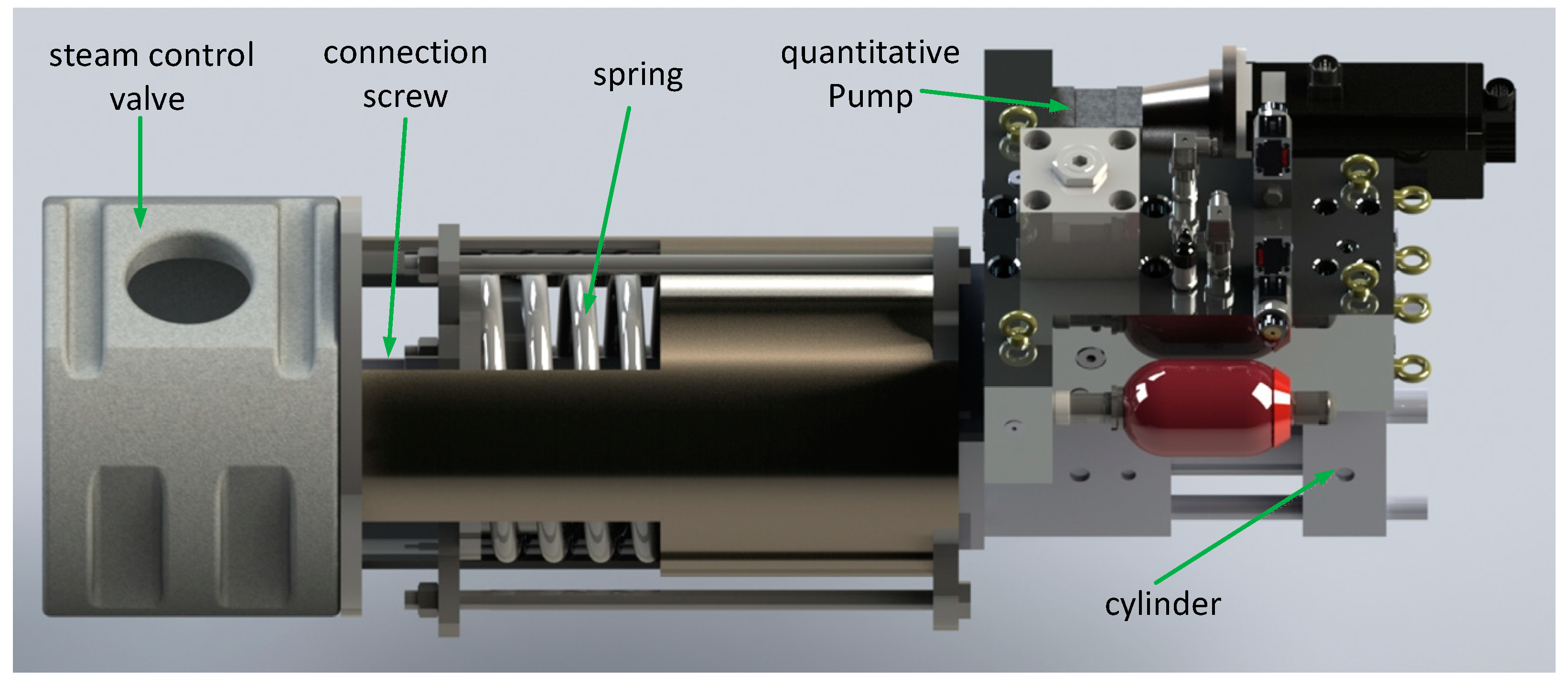
6]. The structural principle of the SM is shown in
Figure 1.
The SM uses a hydraulic cylinder to drive the mechanical connecting rod to adjust the opening of the steam control valve, thereby changing the high-pressure steam intake and finally realizing the overall power control of the steam turbine. In this way, the steam turbine can meet the changing demand of electricity consumption and ensure that the speed is working within the normal range. When the system fails, the pressure in the high-pressure chamber of the hydraulic cylinder is quickly unloaded, the regulating steam valve is quickly closed under the action of the mechanical spring, and the equipment stops running to avoid major accidents. In the field of high-performance control of SM, the position control of the hydraulic cylinder is a key technical issue for the high-performance operation of steam turbines.
In recent years, experts and scholars have never stopped researching on SM, the current research is mainly focused on the overall performance control of the SM and the steam turbine. The drive and control part of the SM usually adopts electrohydraulic servo-valve-controlled technology; that is, the hydraulic station provides system oil supply pressure, and the hydraulic cylinder is controlled by the throttle characteristic of the servo valve to adjust the opening of the steam control valve. Although this technology has good control performance, it has technical defects such as poor antipollution ability, low energy efficiency, large volume size, and limited installation space [
7]. The application of electrohydraulic servo pump control technology in the field of SM has mostly focused on the analysis of structural principles, and there is a lack of in-depth research on its specific control strategies. Several studies have been carried out on SM position control, and many studies have utilized simulations and experiments. Related research status is as follows.
M. Pondini et al. of the Pisa Research Institute used Simulink simulation tools to establish a dynamic model of a steam turbine governor and analyzed the governor’s effect on the stability of the power system [
8]. Annamaria Signorini et al. of General Electric analyzed the working principle and important role of the electrohydraulic servo-valve-controlled system of the SM. According to its working principle, a dynamic model simulation model was established, and the system performance indicators were tested experimentally [
9]. Abhay Patil et al. of Texas A&M University analyzed the dynamic characteristics of the steam turbine under single-phase and air–water two-phase action and obtained the performance law of steam turbine inlet pressure and power input in the speed range [
10]. Mohammad Ali Azizi studied the speed control strategy and transient performance characteristics of steam turbine and discussed the control effects of different control strategies on the variable speed and constant speed operation of the system. Through these studies, the influence of key system parameters on its performance was obtained [
11].
Yuan Xiaohui of Huazhong University of Science and Technology established a virtual power regulation system dynamic model and proposed an imperialist competitive algorithm (ICA) algorithm for its nonlinear control problem, which effectively improved the robustness of the system under load disturbance [
12]. Yan Junjie et al. of Xi’an Jiaotong University established a transient simulation model of a steam turbine power generation system, analyzed the performance indicators of the SM control system, and took power control and operational flexibility as the optimization goals to obtain the best control strategy for the system [
13]. Dong Yuliang et al. designed a virtual system simulation experiment platform based on the working principle of the SM for a steam turbine, which met the specific experimental requirements in terms of openness and sharing of experimental capabilities [
14]. Cao Yifan used a fuzzy controller to ensure stable operation of the system, given the nonlinear chaotic vibration phenomenon of the steam turbine regulation system [
15]. Jiang Jihai et al. proposed a direct-drive electrohydraulic servomotor and analyzed its principle, composition, and characteristics [
16].
This paper proposes a volume control scheme to form an electrohydraulic pump-controlled servomotor technology (referred to as PCSM). In this scheme, the quantitative pump (refers to hydraulic pumps with an axial piston design and a swash plate) is directly connected with two load ports of the hydraulic cylinder driven by the servo motor. This technology replaces traditional servo-valve-controlled servomotors (referred to as SVCSM) and has the advantages of high efficiency, energy savings, high power-to-weight ratio, and environmental friendliness. More importantly, the control system is required to have high enough reliability in the field of thermal power generation. The anti-pollution ability of PCSM is far stronger than that of SVCSM, which greatly improves the reliability of the system. The PCSM is a new application in the field of steam turbines. Although few public documents have been published, electrohydraulic pump control technology has been successfully applied in other high-precision control fields such as vehicle suspension control, robot joint drive, and wind power transmission ratio control. However, the control performance of the PCSM has always been an important factor that impede its promotion. This study improves the system robustness and further improves the position control accuracy, which lays a good foundation for the promotion of the PCSM [
17,
18,
19].
This paper studies the position control of the PCSM for steam turbines, analyzes the working principle of the PCSM, and establishes the mathematical model of the PCSM. On this basis, a sliding mode variable structure control strategy is proposed [
20,
21,
22,
23,
24,
25,
26]. By constructing a switching function to solve the variable structure control law, the nonlinear excitation interference of the system is overcome. The system robustness is improved, and the high-precision control of the SM position is realized.
2. System Overview
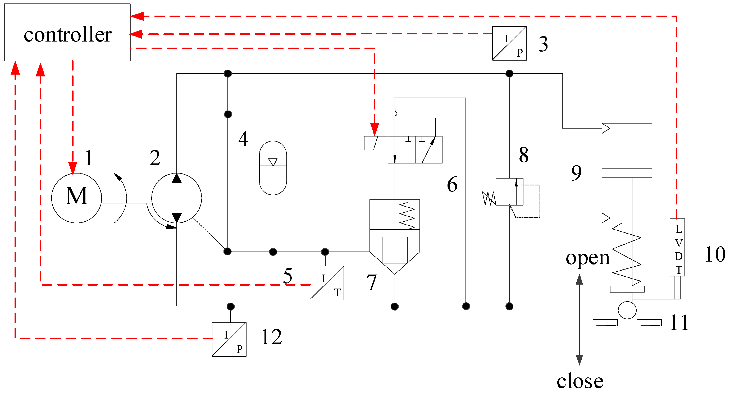
The servomotor-quantitative pump-hydraulic cylinder volume control scheme is proposed in this paper. The volume control scheme, which forms the PCSM technology, is used as the servo driving link of the servomotor position control.
The PCSM includes a servomotor, a quantitative pump, hydraulic valves, an accumulator, a hydraulic cylinder, a servo drive, and a controller.
Figure 2 shows the system composition.
As shown in
Figure 2, the PCSM adopts the servomotor driving quantitative pump form, and the quantitative pump suction and discharge ports are directly connected to high and low-pressure load chambers of the cylinder. The accumulator is connected to the system’s low-pressure chamber, and the accumulator replenishes the hydraulic oil for the system. The relief valve performs pressure overload protection. When the system fails, the two-way cartridge valve and electromagnetic reversing valve work together, and the high-pressure chamber of the cylinder quickly unloads. Because of the action of the mechanical spring, the hydraulic cylinder rod extends and the steam control valve is quickly closed.
The controller collects status information such as system displacement, pressure, and temperature, and then controls the speed of the servomotor through the servo drive to achieve high-precision position control of the hydraulic cylinder. The hydraulic cylinder pushes the connecting rod to realize the precise adjustment of the steam control valve opening. Through the analysis of the working principle of the PCSM, it is concluded that to achieve high-precision position control, mathematical modeling of the core components in the system and analysis of its control principles are required.
3. Mathematical Modeling of the PCSM
The following is the mathematical modeling analysis for the core components of the PCSM, including the servomotor, the quantitative pump, and the cylinder, and the analysis of the load characteristics of the PCSM. Based on this analysis, the position control system of the PCSM is studied.
3.1. Mathematical Model of the Servomotor
In the process of position control of the PCSM, the servomotor is used as the execution terminal of the control algorithm, in position control. The mathematical model for the core components of the servomotor is as follows:
The servomotor stator flux linkage equation can be expressed as follows:
The servomotor stator voltage equation can be expressed as follows:
The servomotor electromagnetic torque equation can be written as follows:
The servomotor motion equation can be written as follows:
where
are the d–q axis components of the stator flux linkage,
are the equivalent inductance of the stator inductance of the d–q axis,
are the stator d–q axis components of the current,
is the permanent magnet flux linkage,
are the d–q axis components of the stator voltage,
is the stator resistance,
is the angular velocity of the motor rotor,
is the electromagnetic torque of the motor,
is the number of pole pairs of the servomotor,
is the servomotor load torque,
is the rotation equivalent converted moment of inertia of the subaxis,
is the mechanical angular velocity of the servomotor, and
is the damping coefficient of the servomotor.
3.2. Mathematical Model of the Quantitative Pump
The quantitative pump is the power element of the PCSM, which provides hydraulic power input for the movement of the cylinder. The flow output of the pump is related to the displacement and speed, and the leakage will affect its flow rate. The quantitative pump mathematical model is as follows:
The flow output equation of the quantitative pump is
where
is the angular velocity of the quantitative pump,
is the rated displacement of the quantitative pump,
is the output flow of the quantitative pump,
is the leakage coefficient of the quantitative pump coefficient, and
is the load pressure.
3.3. Mathematical Model of the Cylinder
The cylinder is the executive element of the steam control valve, which is the executive terminal of the PCSM and the load. The position control of the cylinder determines the opening of the steam control valve. The mathematical model of the cylinder is as follows:
The flow continuity equation of the cylinder is
Hydraulic cylinder as the internal dynamic characteristics of the system is poor executive components. Its response speed constrains the dynamic characteristics of the whole system. Here we analyze the load characteristics of the cylinder, so as to study its performance under external load interference.
The force balance equation between the cylinder and load is
where
is the effective area of the cylinder,
is the cylinder load flow,
is the total leakage of the cylinder,
is the system total compression volume,
is the effective bulk elastic modulus of oil,
is the total mass of the piston and load converted to the piston,
is the viscous damping coefficient of the piston and the load,
is the spring stiffness of the load,
is the output displacement of the cylinder, and
is the external load force acting on the piston.
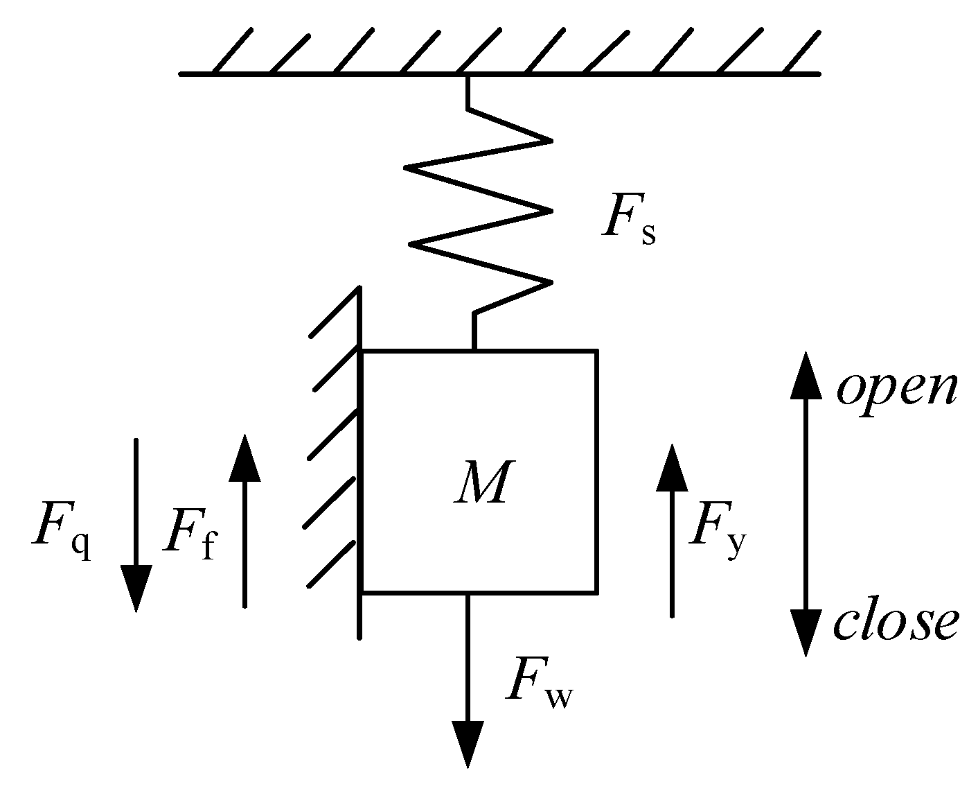
3.4. Load Mathematical Model
The cylinder of the PCSM is subjected to hydraulic pressure, spring force, mechanical friction force, and valve steam force during the movement. Based on the mass–spring system model, the load force of the cylinder was analyzed, as shown in
Figure 3.
All moving masses and external load forces are converted into the equivalent force on the centerline of the piston in the cylinder according to the lever ratio. According to Newton’s second law of motion, the force equation of the system can be obtained as
where
where Stribeck friction model can better describe the relationship between friction force and velocity of mechanical system [
27]. The Stribeck friction model is
where
is the external load force acting on the piston,
is the equivalent spring force,
is the equivalent gravity of the system, is the equivalent fraction of the system,
is the equivalent steam force of the steam control valve,
is unbalanced area of steam control valve,
is the pressure difference before and after steam control valve, and
is the hydraulic driving force of the cylinder,
is external load of system,
is the maximum static friction force,
is coulomb friction,
is Stribeck velocity,
is coefficient of viscous friction,
is experience factor.
3.5. Model Analysis of the Position Control System
A block diagram of the position control for the PCSM can be established by Formulas (5)–(7), as shown in
Figure 4.
From
Figure 4, the position servo open-loop transfer function of the PCSM can be derived as
where
is the total flow–pressure coefficient.
Considering that PCSM has a large elastic load (
K ≠ 0), the transfer function of hydraulic cylinder output displacement to servo motor speed can be obtained from Equation (12):
where
is the total pressure gain of the system.
is the inertial link turning frequency.
is the combined natural frequency.
is the combined damping ratio.
is the hydraulic spring stiffness.
The main performance parameters of servo motor speed affecting the output displacement of hydraulic cylinder are , , and . The proportional system is called the position amplification factor, which represents the sensitivity of servo motor speed to hydraulic cylinder displacement control. The position amplification system changes with the change of working point and is related to the load stiffness.
The integrated natural frequency is the ratio of the stiffness of the hydraulic spring in parallel with the load spring to the load mass. The load stiffness increases the natural frequency of the second-order oscillation link, and the load stiffness reduces the damping ratio of the second-order oscillation link. The natural frequency has an important effect on the response speed of the system.
The inertial link turning frequency is the ratio between the stiffness and damping of the hydraulic spring and the load spring in series. The varies with the load stiffness. If the load stiffness is very small, the is very small, and the inertia link can be approximately regarded as an integral link.
4. Control Scheme
The PCSM has nonlinearity and parameter perturbation. It is difficult to meet the robustness requirements of the system with simple proportion integration differentiation (PID) control. This paper proposes a sliding mode variable structure control algorithm. The dynamic invariance of the sliding mode variable structure control algorithm will effectively overcome the disturbance of nonlinear factors to the control in the SM. The open-loop transfer function of the position servo in the PCSM is simplified into the transfer function of the following form:
where
is the system control input command, and
is the external compound interference of the system.
Selecting the output displacement of the cylinder as the state variable of the system, we can get
Further, the state equation of the position control system of the PCSM is
Let
r be the system input signal, and the system deviation
e =
r −
y, we can make
The above formula can be further written as
The error vectors of the sliding mode surface and the sliding mode surface of the position control system in the selected PCSM are
The sliding mode variable structure control switching function can be obtained as
Using exponential reaching law
, then
After finishing, the output of the system controller is
5. Experimental Research
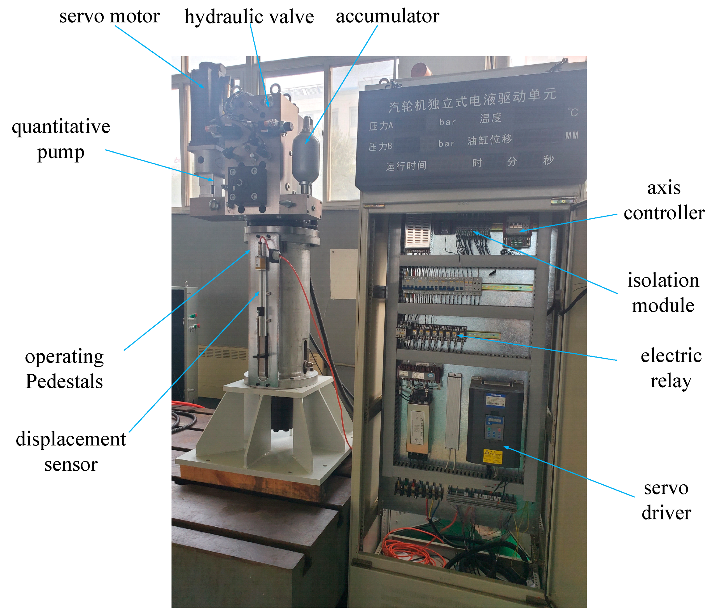
In this study, we relied on the PCSM test platform to test the proposed sliding mode variable structure control strategy. The whole test platform is shown in
Figure 5. A servomotor, a quantitative pump, hydraulic valves, and an accumulator were integrated into the cylinder. The cylinder was connected with the mechanical spring through the control seat. The electric control cabinet integrated the axis controller, the servo drive, and the isolation module.
The axis controller MACS software (here refers to Moog Axis Control Software) was used to compile the monitoring and data acquisition interface of the PCSM experiment platform based on codesys (here refers to Controlled Development System), as shown in
Figure 6.
The working parameters of the PCSM test platform are shown in
Table 1.
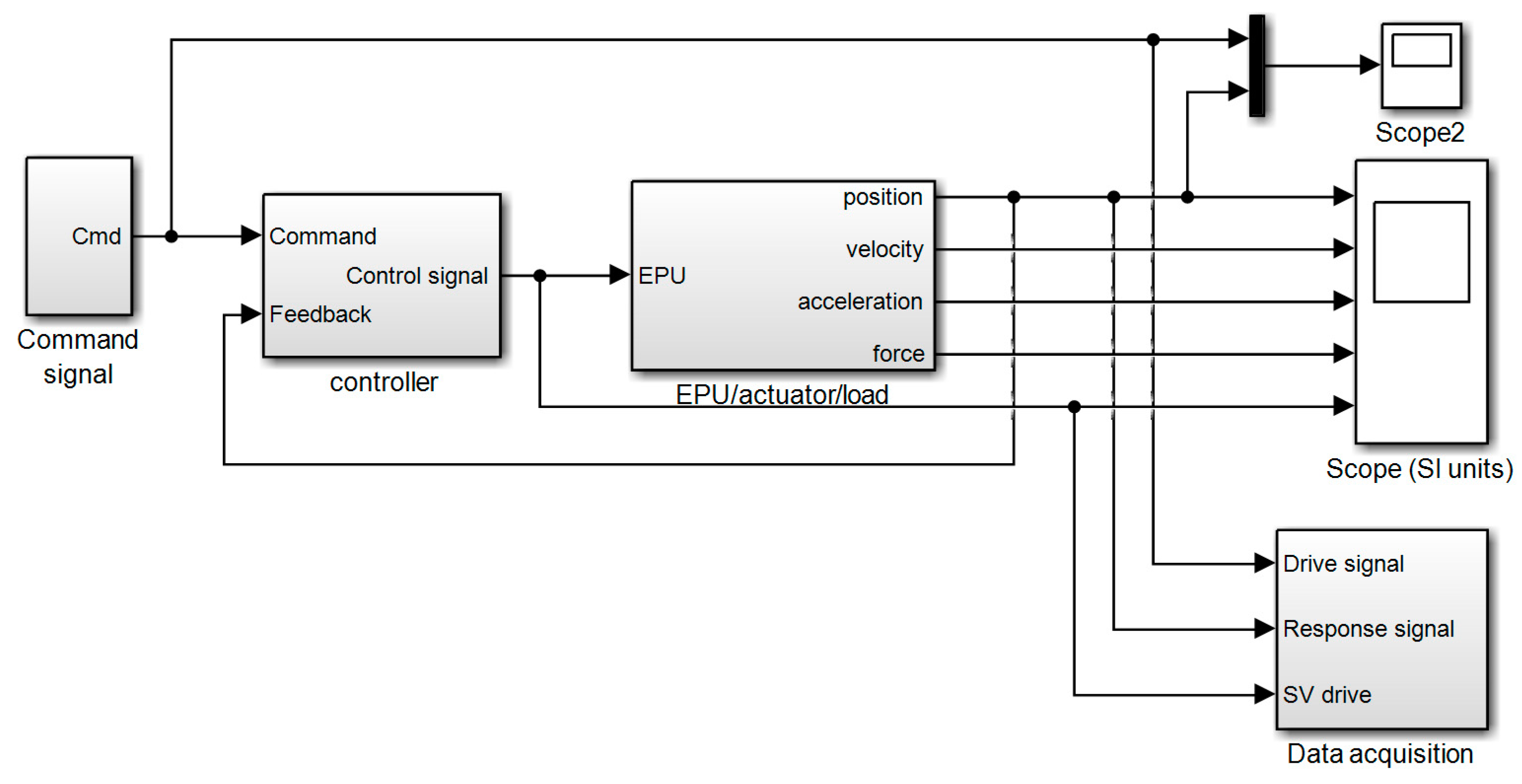
Based on the PCSM test platform, according to the proposed sliding mode variable structure control algorithm, a system simulation platform was built using MATLAB/Simulink, including the servomotor module, quantitative pump module, cylinder module, and controller module. The simulation platform is shown in
Figure 7.
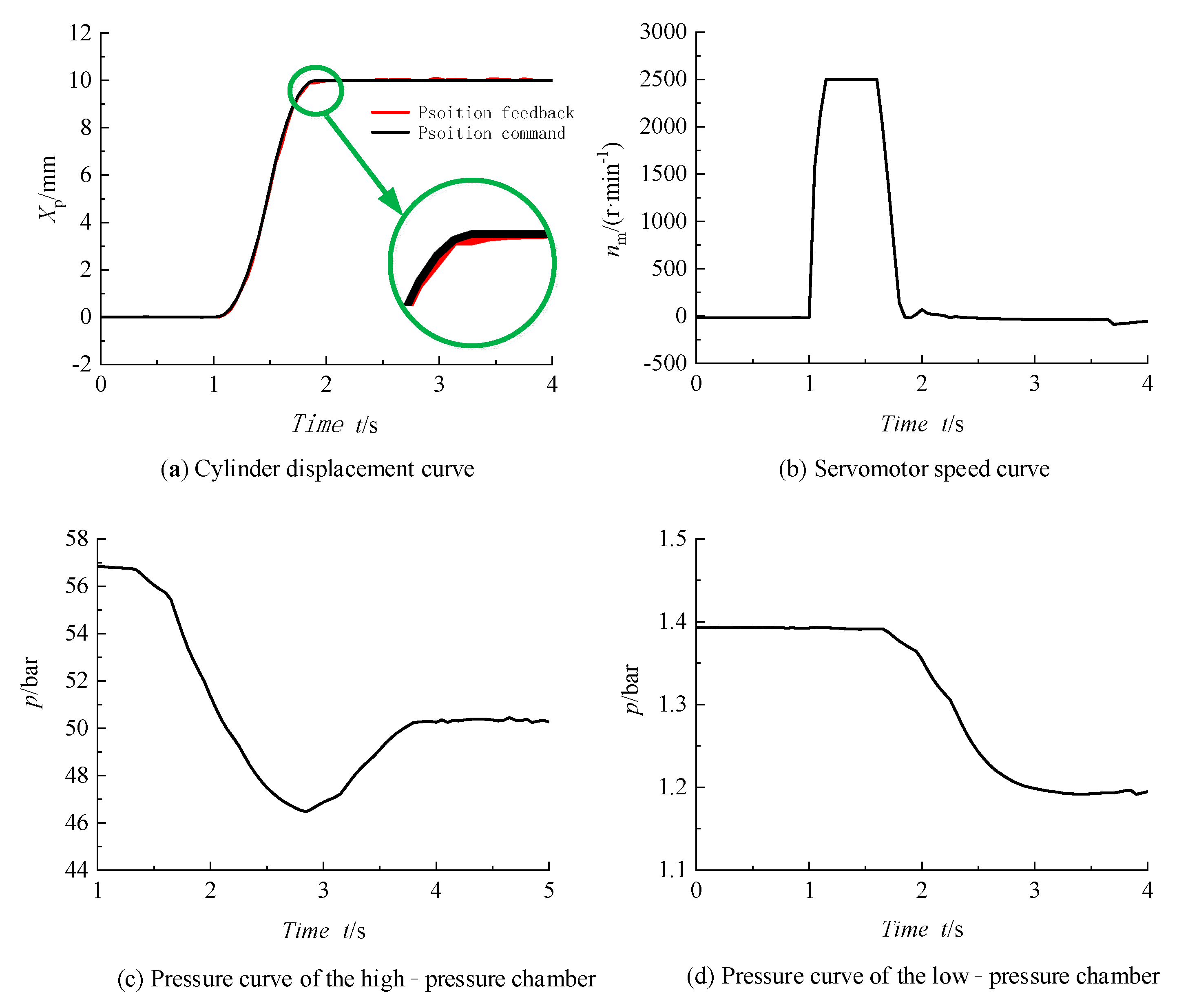
The off–line semi–physical test of the SM and the steam turbine is carried out. Simulink is used to establish simulation models of the equivalent friction force of the system and the equivalent steam force of the steam control valve according to the mathematical models of Equations (8) and (9). Download to the system axis controller. In the actual test process, the simulation force is superimposed with the actual spring force of the spring seat and the hydraulic driving force of the hydraulic cylinder in the actual working process of the test bench to obtain the PCSM test platform environment. During the test, the valve regulating system of the steam turbine was simulated. When the steam control valve was closed, the cylinder of the PCSM received the position command to move from 0 to 10 mm. The test data are shown in
Figure 8.
Figure 8 shows that using the sliding mode control strategy, the cylinder displaced from 0 to 10 mm, and the servomotor speed and system pressure responded quickly. At this time, the pressure in the high–pressure chamber was reduced, the lowest pressure in the high–pressure chamber was 46 bar, and the pressure in the low–pressure chamber was reduced by about 0.2 bar. The peak speed of the servomotor could reach 2500 r/min, and the position of the cylinder reached the steady–state position within 2 s. The steady–state accuracy of the cylinder position was ±0.01 mm.
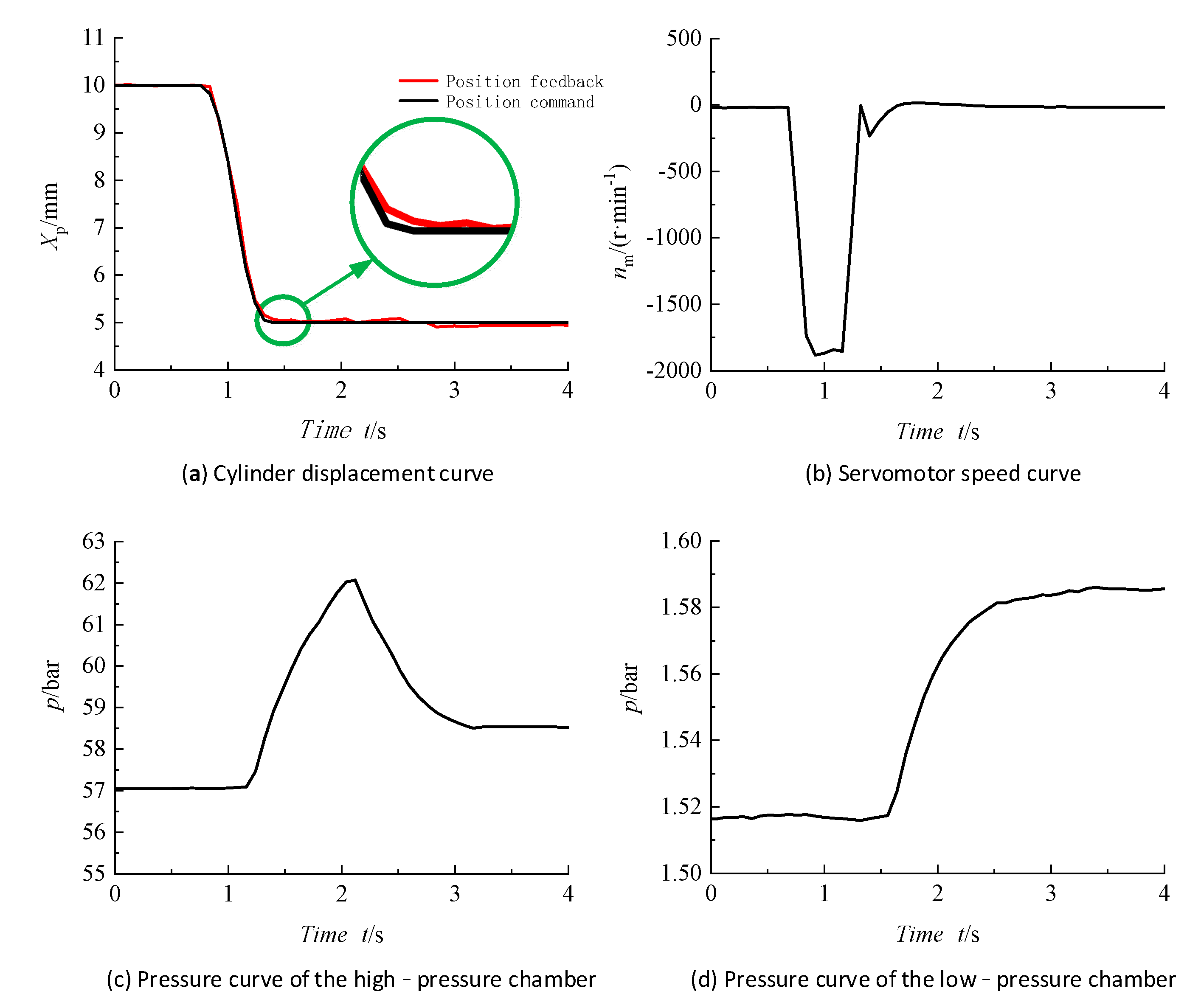
When the steam control valve was opened, the cylinder of the PCSM received the position command to move from 10 to 5 mm. The test data are shown in
Figure 9.
Figure 9 shows that using the sliding mode control strategy, the cylinder displaced from 10 to 5 mm, and the servomotor speed and system pressure responded quickly. At this time, the peak pressure of the high–pressure chamber was 62 bar, and the pressure in the low–pressure chamber increased by about 0.2 bar. The peak speed of the servomotor could reach −1800 r/min, and the position of the cylinder reached the steady–state position within 1.5 s. The steady–state accuracy of the cylinder position was ±0.01 mm.
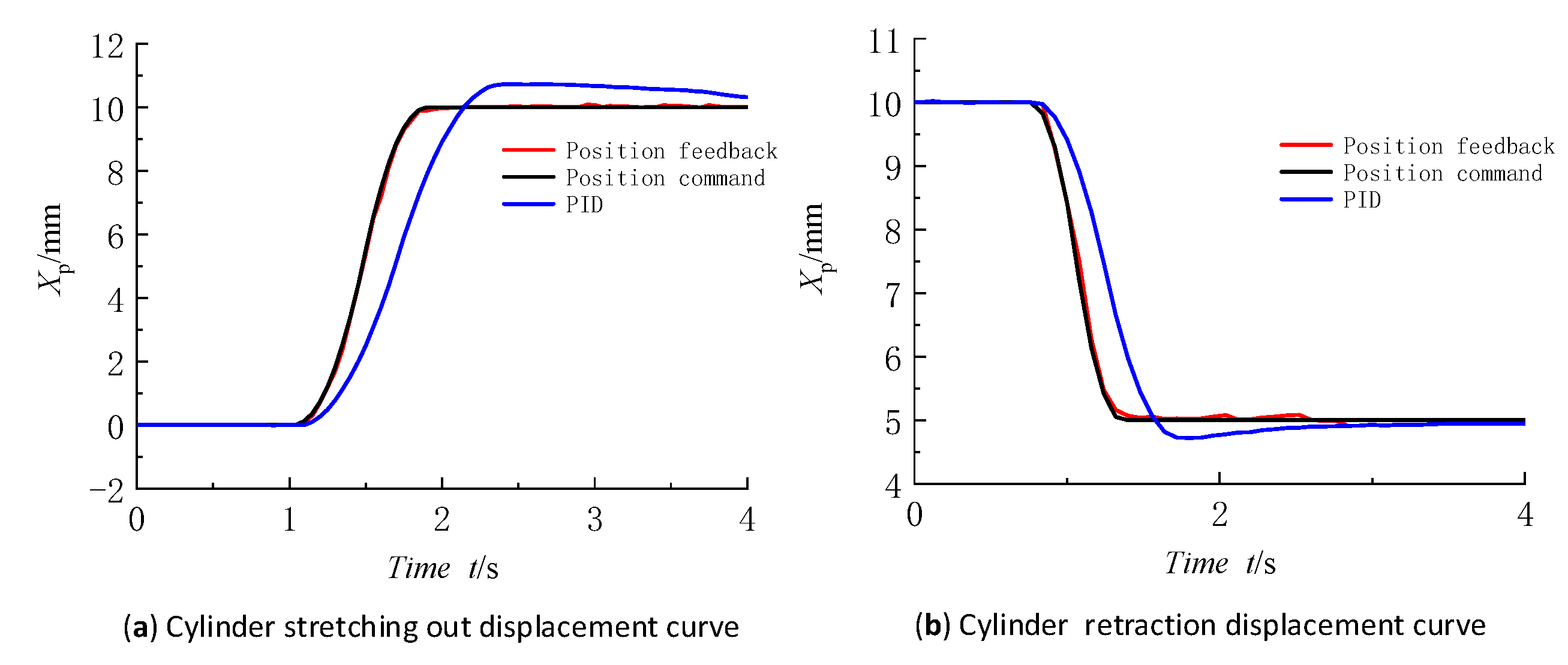
In order to confirm the superiority of the control strategy adopted in this study, a simple PID controller is set up in this paper for comparison with the sliding mode variable structure control, as shown in the
Figure 10.
As shown in
Figure 10, in the stretching and retraction stage of the hydraulic cylinder, compared with the displacement feedback obtained by simple PID adjustment, the following effect and control precision of the sliding mode variable structure control strategy are greatly improved. It fully shows that the sliding mode variable structure control strategy has a good control performance when applied to the PCSM system.


