Article

Light Reflection Loss Reduction by Nano-Structured Gratings for Highly Efficient Next-Generation GaAs Solar Cells

by
Narottam Das
1,2,*,
Devanandh Chandrasekar
3,
Mohammad Nur-E-Alam
4 and
M. Masud K. Khan
1,2
1
School of Engineering and Technology, Central Queensland University Australia, Melbourne, VIC 3000, Australia
2
Centre for Intelligent Systems, School of Engineering and Technology, Central Queensland University, Brisbane, QLD 4000, Australia
3
Neon Solar System, Carrum Downs, VIC 3201, Australia
4
Electron Science Research Institute, Edith Cowan University, Perth, WA 6027, Australia
*
Author to whom correspondence should be addressed.
Energies 2020, 13(16), 4198; https://doi.org/10.3390/en13164198
Submission received: 9 July 2020 / Revised: 2 August 2020 / Accepted: 10 August 2020 / Published: 14 August 2020
(This article belongs to the Special Issue Nano-Structured Solar Cells 2020-2022)

Abstract

:
This paper mainly focuses on increasing the conversion efficiency of GaAs solar cells by reducing the light reflection losses. The design of nano-structured gratings and their light trapping performance are modelled and optimised by using the finite-difference time-domain (FDTD) method. The sunlight directly impinges on the solar panel or cells, then a portion of the incident sunlight reflects back to the air from the surface of the panel, thus leading to a reduction in the light absorption capacity of the solar cells. In order to proliferate the light absorption capacity of solar cells nano-grating structures are employed, as they are highly capable of capturing the incident sunlight compared to a conventional (or flat type) solar cell, which results in generating more electrical energy. In this study, we design three different types of nano-grating structures, optimise their parameters and their performance in light capturing capacity. From the simulation results, we confirm that that it is possible to reduce light reflection losses up to 27%, by using the nano-grating structures, compared to conventional type solar cells. This reduction of reflection losses helps to improve the conversion efficiency of next-generation GaAs solar cells significantly for a sustainable green Earth.

Graphical Abstract

1. Introduction

According to the latest report published by the United Nations Department of Economic and Social Affairs (UN DESA), the world population is expected to increase by 2 billion within the next 30 years. The growth rate of world population indicates that the current world population could jump from 7.7 billion (currently) to 9.7 billion by 2050, and it is also projected to have a peak of approximately 11 billion by 2100 [1]. For this large number of populations, besides all the fundamental needs, there will be a huge demand for energy and meeting that energy demand will be a key challenge and big obstacle towards dreaming of a sustainable green globe. Currently, of the global energy demand, the majority of energy generation is fossil fuels based, which is supposed to be running out very rapidly. Additionally, to restrain the carbon dioxide (CO2) concentration in the air, it is necessary to reduce the energy harvest from burning fossil fuels by up to 3 TW within the next 25 years and to produce the rest of the required energy from renewable energy sources [2,3,4]. However, as an alternative to fossil fuel energy, and to minimise CO2 production, solar cells, among all the renewable energy resources, can provide an efficient and environmentally friendly solution, for a sustainable green earth. Since 2010, the average energy-related CO2 emissions have risen by ~1% per year, and are becoming one of the hardest and most expansive barriers to the reduction and elimination of CO2 emissions, from a global and broad socio-economic development point of view. The global decarbonisation goal reflects the need for innovative renewable technologies, including the development and improvement of solar photovoltaic (PV) systems, with other measures such as government initiatives, government and industrial investments, proper business models, and behavioural adaptation to reach zero emissions [5]. On the other hand, the current world is deeply suffering from the novel coronavirus (COVID-19) pandemic situation. However, the post-COVID world recovery measures could benefit from energy engineering solutions, such as flexible and smart power grids, efficiency solutions, electric vehicle charging, energy storage, interconnected hydropower, green hydrogen, various solar PV systems, and other technology investments consistent with long-term energy and climate change sustainability. In response to the current COVID-19 pandemic situation, it is recommended to secure the advantages of renewable energy sources, and their efficiency, to pave the way for a clean, low-carbon global economy, and towards a green sustainable Earth for all lives [5,6]. A very recent report published in Reference [7], made public that the ideal weather conditions and lower levels of pollution than normal mean solar can provide record levels of cheap, clean energy/power to the grid. According to the live data from the Sheffield Solar Live PV tracker, which is run by the University of Sheffield, United Kingdom (UK), solar energy generation reached a peak, a new record high of 9.68 GW in one week that relates in large part to a significant slump in air pollution levels, resulting in clearer skies for all livelihoods.
Since the discovery of solar cells in the 19th century, they have been widely used in various renewable energy generation projects including solar farms, roof-top installations, portable solar battery bank systems, and spacecraft [8,9,10,11,12,13,14,15,16,17]. Recently, solar cells have also been used in building integrated photovoltaics (BIPV) systems for harvesting solar energy, towards the goal of self-sustainable modern infrastructures, such as glass-greenhouse, bus stops, and smart building components i.e., energy generating and saving PV glass [18,19,20,21,22,23]. However, scientists and researchers around the world are still conducting research in this area, including the development of various types of solar cells and focusing on improving the conversion efficiency as well [15,24,25,26,27,28,29,30,31,32,33,34,35,36,37,38]. There are several factors, from structural defects to resistance to shading effects, that affect the conversion efficiency, as well as the overall performance, of solar cells. Light reflection loss is one of the key factors that affect light propagation reaching to the active region of the solar cells and consequently reduce the amount of light absorption, which has a significant impact on the conversion efficiency of solar cells. In order to improve the conversion efficiency of solar cells, anti-reflective (AR) thin film coating is used as an additive feature to minimise the reflection losses. However, their performance is also limited to a certain wavelength region, together with some downsides, such as thermal and adhesive mismatch with the substrates, which require specific choice of material and geometry [36,37,38,39,40,41,42].
Due to the cells ability to trap the incident light, subwavelength structures have applications in several areas of research, from medical therapy and sensing, to imaging and PV systems [43,44,45]. They have also been demonstrated to be promising candidates for realising high conversion efficiency in solar cells, due to their low reflection losses. A nano-structured medium, such as gratings or modified and texturised surfaces, can act as a homogeneous medium, with an effective refractive index, only if the incident light wavelength is bigger than that of the medium. Therefore, subwavelength grating (SWG) structures help to achieve gradual changes in refractive index and thus to ensure enhanced light trapping properties compared with planar or flat type thin film coatings or nano-media [46,47]. A significant number of research works have been conducted worldwide and demonstrated using different types of nano-structures, such as diffractive nano-gratings, nanoholes, nanoparticles, double-gratings, and random textures for the enhancement of light absorption in solar cells [48,49,50,51,52,53,54,55,56,57,58].
The finite-difference time-domain (FDTD) simulation tool is used to design, model, and analyse the properties of nano-grating structures. For this simulation, we considered three different types of nano-grating structures, such as triangular, trapezoidal (hatch top or truncated cone), and rectangular shapes. The nano-gratings’ height and aspect ratio were varied during the simulation process in order to find the best conditions for capturing more of the incident light into the GaAs substrate, for high conversion efficiency of solar cells. The computation was based on the principle of FDTD method, i.e., a mesh grid network, and Maxwell’s equations [59,60]. The performance of nano-grating structures was simulated and their properties (light transmission, reflection, and absorption rates) were evaluated by considering the grating shapes, design aspect ratio, and the field components distribution as well.
This paper is organised as follows. Section 2 briefly describes the properties of moth’s eye light collection ability, characteristics of an anti-refractive coating layer, and the geometry design for different types of nano-grating shapes. Section 3 describes the simulation results and discussion, followed by a conclusion in Section 4.

2. Moth’s Eye, Antireflective Coating, and Nano-Gratings

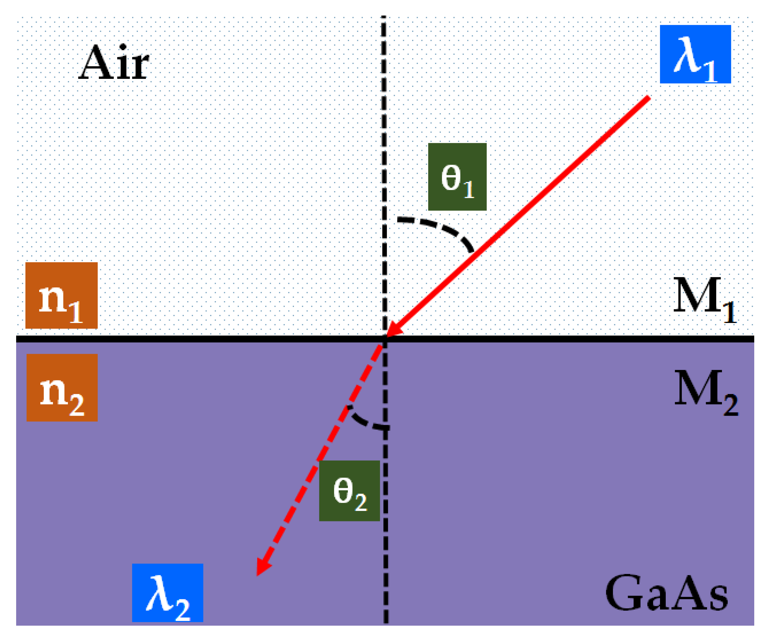
2.1. Principle of Moth’s-Eye

An efficient solar cell has to reflect the minimum and absorb the maximum amount of the incident light. The use of an AR structure was inspired by the natural model of moth’s eyes [61,62]. Japanese researchers initially found that this useful property exists in nature’s intelligent creature: moth’s eyes. Hence, they made an antireflective film coating on solar panels for better utilisation of sunlight.
The moth-eye film was produced by Noboru Yamada, a researcher at the Nagaoka University of Technology, Japan, who worked in research collaboration with analysts at Mitsubishi Rayon Co., Ltd. Tokyo, Japan, and Tokyo Metropolitan University, Tokyo, Japan [63]. Utilising anodic permeable alumina molds, they were able to nano-imprint the micro-structure of moth’s eyes into a form of resin, and this gave a high efficiency, extensive range, and straightforward technique for producing the AR layer. These “moth eye” structures are commonly known as antireflective subwavelength structures (SWSs) that can effectively suppress the reflection in broadband and omni-directional ranges. Successful fabrications of these types of antireflective SWSs using various physical vapor nano/micro fabrication processes are reported in the literature [59,61,62,63,64]. Figure 1 shows an example of the nanoscopic structure of a Moth’s eye [65]. Based on the outcome of various tests conducted on a silicon solar panel coated with this resin, they concluded that use of this thin film can improve the light absorption properties compared with the conventional solar panel.

2.2. Antireflection Coating

As mentioned, the efficiency of solar cells can be increased using an anti-reflection coating, which reduces the amount of light reflection for certain ranges of wavelength. The minimum reflectance can be calculated for different polarisations, namely, s-polarisation and p-polarisation, as shown in the following Equations (1) and (2).
RS = ((n1 Cosθ1 − n2 Cosθ2)/(n1 Cosθ1 + n2 Cosθ2))2
RP = ((n1 Cosθ2 − n2 Cosθ1)/(n1 Cosθ2 + n2 Cosθ1))2
where, n1 and n2 represent the refractive indices of media 1 and 2 which are air and GaAs. θ1 and θ2 represent the angle of incidence and angle of refraction, respectively. λ1 and λ2 represent the wavelength of incident medium M1 and refracted medium M2, as shown in Figure 2.
On the other hand, for an unpolarised light, the total reflection coefficient can be explained as follows [66]:
Rtotal = (RS + RP)/2
Furthermore, Figure 2 describes the relationship between the angle of incidence and angle of refraction using Snell’s law. It represents the light reflection diagram of flat GaAs substrate. The incident light angle (θ1) is the angle between the incident ray and the surface normal. The refracted light angle (θ2) is the angle between the refracted ray and the surface normal. When the light is near normal incidence, for both polarizations, the reflection coefficient using Fresnel equation can be given by [67]:
Rtotal = RS = RP = ((n1 − n2)/((n1 + n2))2

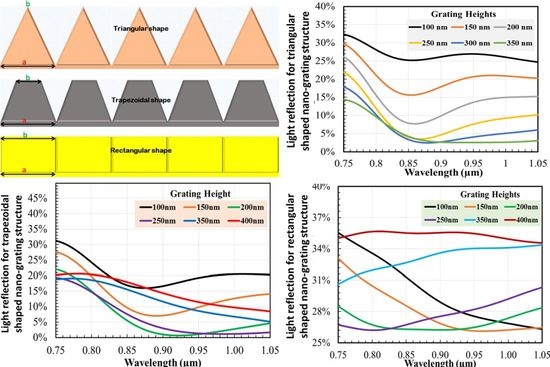
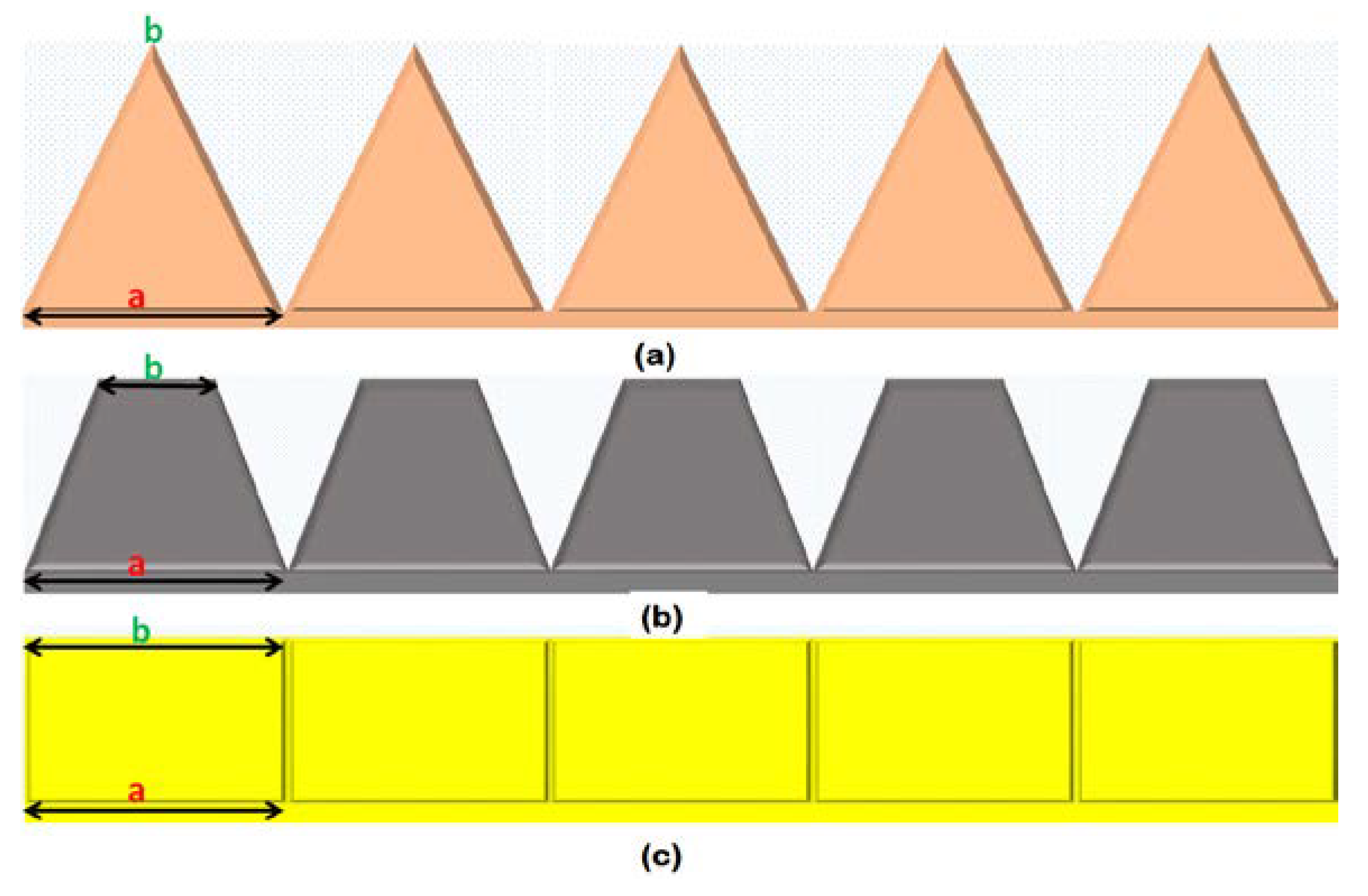
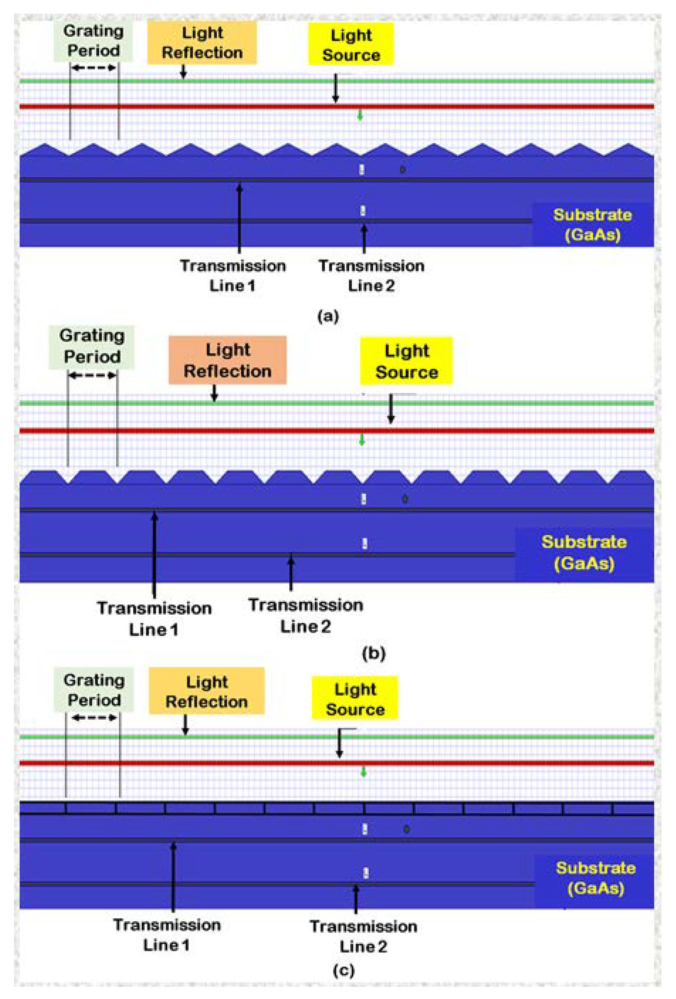
2.3. Different Types of Nano-Grating Shapes

In this section, we present the concept of nano-grating shapes. The modeled nano-grating shapes are: (i) rectangular, (ii) trapezoidal with 0.5 aspect ratio, and (iii) triangular. The aspect ratio is defined as the proportion of the top base width (a) over the bottom base (b) of a trapezoid, triangle, or rectangle nano-grating (i.e., a/b), as can be seen in Figure 3. These geometries are represented in Figure 3. Different shapes’ effect on the light reflection and light trapping behavior of nano-structures has been an interesting topic for researchers [68,69]. We investigated different shapes to confirm that having inclined walls for nano-structures provides a better AR coating.

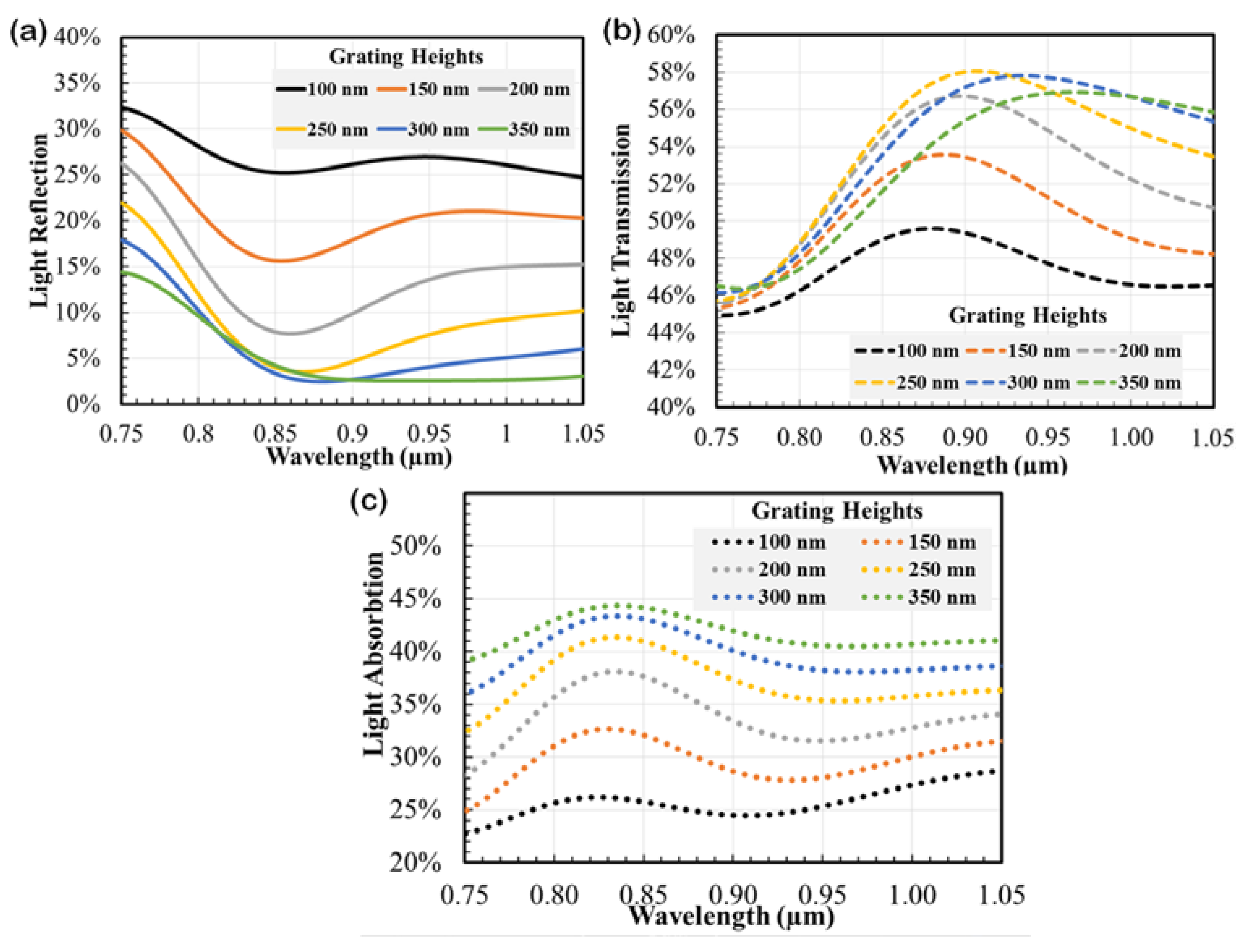
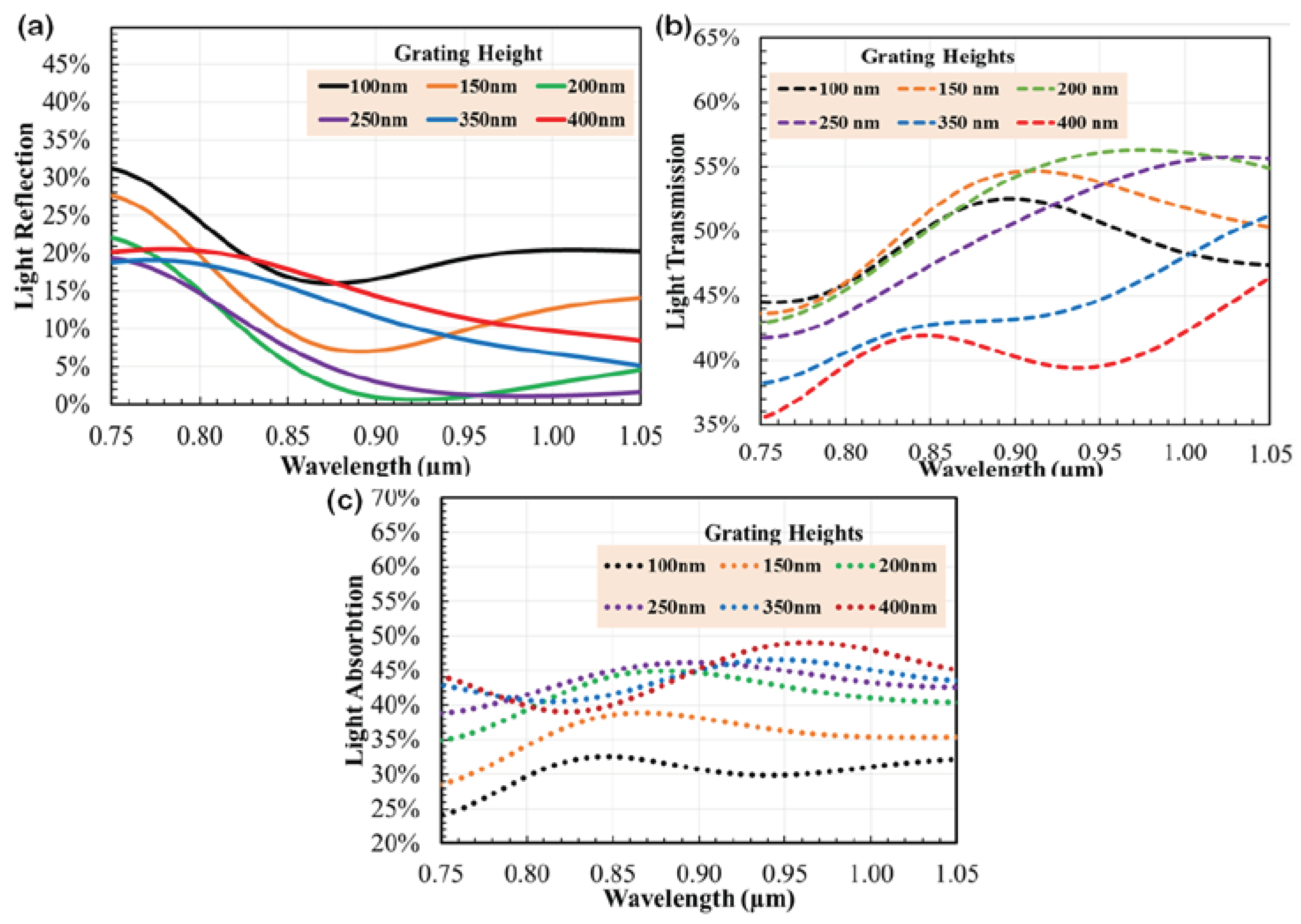
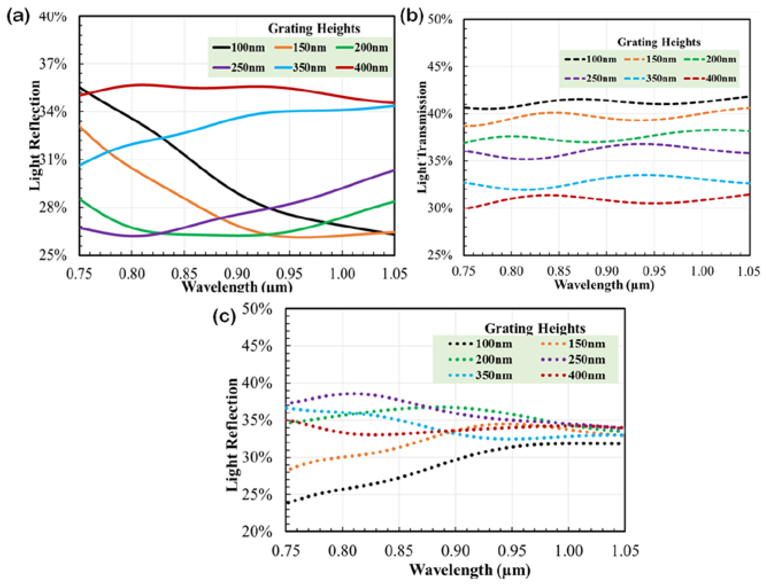
3. Simulation Results and Discussion

Based on the properties of light reflection and light absorption rates, the simulation results of different nano-grating structures are discussed in this section. Opti-FDTD (which works based on Maxwell’s equation) software package was used in this work to perform the diffractive optics simulation. This commercially available software package is versatile and capable of modeling and mixing up various elements, such as the light propagation, scattering and diffraction, reflection and polarisation impacts. It can likewise demonstrate material anisotropy and scatter, with no pre-supposition of field conduct, for example the gradually differing amplitude estimation. The method takes into consideration the compelling and examination of sub-micron i.e., nano-scale devices, with the finest structures over any wavelength and feature size, and with any type of structure, such as, regular or irregular shapes. The advanced computing technologies help to minimise the existing limitations of conventional FDTD method, related to handle dispersion with some metal components, or when modeling some subwavelength size structures.
Figure 4 present the specific designs for the modelling of triangular, trapezoidal, and rectangular-shaped nano-gratings. The aspect ratio for the triangular-shaped nano-grating was zero (0), while for the rectangular-shaped nano-grating it was one (1). These shapes, along with the trapezoidal-shaped nano-gratings with the aspect ratio of 0.5, were used in the simulation, and for analysis of the light reflection, transmission, and absorption behavior of the SWG structures in solar cells. The two-dimensional FDTD mesh cell size for this study was 5 nm, and a time step of 0.1/s was used. As shown in Figure 4, two lines were designed above the design structures, i.e., red and green lines. The red represents the incident line as sunlight that impinges on the grating zone, and the reflected light can be calculated at the green line (i.e., the light reflection losses). Moreover, there are two more lines defined in the substrate which represent the transmission lines 1 and 2 (i.e., the amount of light transmitted into the GaAs substrate). The nano-structured gratings were designed on a GaAs substrate. For these simulations, the incident light wavelength and the nano-grating period were both kept constant at 830 nm. The grating height that describes the height of the nano-grating structure from the base surface to the upper surface, was kept from 0.05 µm to 0.4 µm.
Figure 5a,b show the light reflection and transmission spectra for triangular-shaped nano-gratings in the range of wavelengths from 0.75-μm to 1.05-μm. In this work, the wavelength range 0.75–1.05 µm was considered by keeping in mind that the saturation property of the GaAs, as described in Reference [70]. The grating heights were varied from 100 nm to 400 nm. It was confirmed that an increase in nano-grating height leads to a reduction in light reflection, and this trend was satisfied for all nano-grating heights, with reflection amount saturates in the range of 300 nm~350 nm. The simulated results show that when the nano-grating height was ~300 nm, the reflection loss was minimum. Figure 5c shows the light absorption rate for triangular-shaped nano-gratings. The simulated results confirmed that with the increase in nano-grating heights the light absorption increased and reached saturation when the height was around 300 nm~400 nm. The light absorption data were accounted using the obtained light reflection and light transmission data by following a simple formula, as written below:
LA = 1 − LT − LR
where LA represents the rate of light absorption, LR represents the rate of light reflection, and LT represents the rate of light transmission.
The obtained light reflection and transmission spectra for trapezoidal-shaped nano-gratings are presented in Figure 6a,b. When the nano-grating height increased, the light reflection decreased and reached saturation around 200 nm~250 nm. It was evident that when the nano-gratings height was ~200 nm, the reflection loss was minimum. Figure 6c shows the light absorption rate for trapezoidal-shaped nano-grating structures with different heights ranging from 100 nm to 400 nm. As we expected, with increasing the nano-gratings height, the light absorption increased and reached saturation around 200 nm~300 nm. It was also clear that at the wavelength of 830 nm, the light absorption rate for 200 nm and 250 nm was very close. The capacity of light absorption increased gradually when the nano-grating height became larger.
Figure 7a,b show the light reflection and transmission spectra for rectangular-shaped nano-gratings with the nano-grating heights ranging from 100 nm to 400 nm. The simulation results confirmed that the light reflection reduced with increasing the height and reached saturation around 200~250 nm. The reflection loss was minimum when the nano-grating height was ~200 nm. The light absorption curves for the rectangular-shaped nano-grating structures, for different grating heights from 100 nm to 400 nm, are shown in Figure 7c. This structure also represented the saturation of absorbed light around 250 nm~300 nm, and the capacity of light absorption decreased gradually afterwards, with decreasing nano-grating heights. The simulation results presented in this paper are in good agreement with the results reported in References [70,71].
From the above presented results, it can be clearly noticed that the grating parameters played a significant role in the light absorption properties of the nanostructures. In addition, with the increment of incident angle, the reflection of p-polarised light decreased until it reached the minimum reflection level at an angle of 75° before it started to rise again. However, the reflection of s-polarised light always increased for any angle of incidence. The light reflection of un-polarised remained at a constant stage from the beginning 0° to 60° and then increased exponentially afterwards as observed and explained in detail in our previously published article [72].

4. Conclusions

We have demonstrated the design, simulation, and analysis results of the light capturing properties of nano-gratings with different shapes and geometries. The optimised nano-structures, to be applied on top of the GaAs solar cells, showed the best optical properties (i.e., light transmission, reflection, and absorption), and enhanced the light absorption capacity of solar cells for the improvement of conversion efficiency. It is evident from the simulation results that triangular-shaped nano-grating structures can absorb more light into the GaAs substrate compared with other types of nano-grating shapes. The reason is that a series of consecutive reflections occur in the grooves (i.e., edges) of the inclined triangular walls, and more energy localisation happens due to the existence of sharp edges. Moreover, using antireflective layer properties leads to several-step changes in the refractive indices of the grating geometry. These simulation results confirmed that the use of nano-grating structures enables up to 27% higher light absorption capacity than conventional solar cells, and thus can increase the conversion efficiency of GaAs solar cells as expected [73]. Based on the achieved simulated results, it can be concluded that the reduction of light reflection losses will significantly increase the conversion efficiency of GaAs solar cells.

Author Contributions

Conceptualisation, N.D.; methodology, N.D. and D.C.; formal analysis, N.D. and D.C.; investigation, N.D. and D.C.; writing—original draft preparation, N.D. and D.C.; writing—review and editing, N.D., M.N.-E.-A. and M.M.K.K.; visualisation and consultation, N.D. and M.N.-E.-A. All authors have read and agreed to the published version of the manuscript.

Funding

This research has been partially supported by CQUniversity Australia, School of Engineering and Technology New Staff Research Grant RSH5171, 2019.

Acknowledgments

The authors would like to acknowledge the School of Engineering and Technology, Melbourne, Victoria; Centre for Intelligent Systems, Brisbane, QLD, Central Queensland University, Australia.

Conflicts of Interest

The authors declare no conflicts of interest for this research.

References

  1. United Nations, Department of Economics and Social Affairs. Available online: https://www.un.org/development/desa/en/news/population/world-population-prospects-2019.html (accessed on 16 June 2020).
  2. International Energy Outlook 2010, A Report by the Office of Integrated Analysis and Forecasting, U.S. Energy Information Administration, U.S. Department of Energy (July 2010). Available online: https://www.eia.gov/outlooks/archive/ieo10/pdf/0484(2010).pdf (accessed on 11 August 2020).
  3. Sterling, B. Renewistan. Available online: http://www.wired.com/beyond_the_beyond/2009/01/renewistan/ (accessed on 11 April 2011).
  4. Wirman, C. Carbon Dioxide Emissions from Electricity Generation in 2015 Were Lowest Since 1993. U.S. Energy Information Administration. Available online: http://www.eia.gov/todayinenergy/detail.cfm?id=26232 (accessed on 10 January 2020).
  5. IRENA’s Global Renewables Outlook: Energy Transformation 2050. Available online: https://www.irena.org/publications/2020/Apr/Global-Renewables-Outlook-2020 (accessed on 19 June 2020).
  6. Publication of Council of European Energy Regulators (CEER) “Keeping the Lights on Saves Lives—Energy Sector and Regulators Guarantee Energy Supply during Lockdown” of 14 April 2020. Available online: https://www.ceer.eu/documents/104400/-/-/9ab3bcce-b191-4414-4e1b-97e6545c24fd (accessed on 19 June 2020).
  7. UK Solar Smashes Generation Records during Covid-19 Pollution Slump. Available online: https://reneweconomy.com.au/uk-solar-smashes-generation-records-during-covid-19-pollution-slump-85451/ (accessed on 19 June 2020).
  8. Andreev, V.M. GaAs and High-Efficiency Space Cells. In Chapter-1, Practical Handbook of Photovoltaics Fundamentals and Applications, 2nd ed.; Academic Press: Cambridge, CA, USA, 2012; pp. 399–416. [Google Scholar]
  9. Lam, L.T.; Branstetter, L.; Azevedo, I.L. A sunny future: Expert elicitation of China’s solar photovoltaic technologies. Environ. Res. Lett. 2018, 13, 034038. [Google Scholar] [CrossRef]
  10. Buitenhuis, A.J.; Pearce, J.M. Open-source development of solar photovoltaic technology. Energy Sustain. Dev. 2012, 16, 379–388. [Google Scholar] [CrossRef] [Green Version]
  11. Gul, M.; Kotak, Y.; Muneer, T. Review on recent trend of solar photovoltaic technology. Energy Explor. Exploit. 2016, 34, 485–526. [Google Scholar] [CrossRef] [Green Version]
  12. Vaishnav, P.; Horner, N.; Azevedo, I.L. Was it worthwhile? Where have the benefits of rooftop solar photovoltaic generation exceeded the cost? Environ. Res. Lett. 2017, 12, 094015. [Google Scholar] [CrossRef]
  13. Davies, J.; Joglekar, N. Supply chain integration, product modularity, and market valuation: Evidence from the solar energy industry. Prod. Oper. Manag. 2013, 22, 1494–1508. [Google Scholar] [CrossRef] [Green Version]
  14. How is Solar Energy Used? The 5 Most Common Examples of Solar Power. Available online: https://news.energysage.com/most-common-solar-energy-uses/ (accessed on 19 June 2020).
  15. Bagher, A.M.; Vahid, M.M.A.; Mohsen, M. Types of solar cells and application. Am. J. Opt. Photonics 2015, 3, 94–113. [Google Scholar] [CrossRef] [Green Version]
  16. Dhal, S.B.; Agarwal, A.; Agarwal, K. Solar powered mobile power bank systems. Am. J. Electr. Electron. Eng. 2016, 4, 148–151. [Google Scholar]
  17. Gurung, A.; Qiao, Q. Solar charging batteries: Advances, challenges, and opportunities. Joule 2018, 2, 1217–1230. [Google Scholar] [CrossRef] [Green Version]
  18. Nur-E-Alam, M.; Vasiliev, M. Transparent Solar Windows: From Labs to Industry, Towards Smart Cities. Encyclopedia 2020. [Google Scholar] [CrossRef]
  19. Vasiliev, M.; Nur-E-Alam, M.; Alameh, K. Recent developments in solar energy-harvesting technologies for building integration and distributed energy generation. Energies 2019, 12, 1080. [Google Scholar] [CrossRef] [Green Version]
  20. Vasiliev, M.; Nur-E-Alam, M.; Alameh, K. Initial field testing results from building-integrated solar energy harvesting windows installation in Perth, Australia. Appl. Sci. 2019, 9, 4002. [Google Scholar] [CrossRef] [Green Version]
  21. ClearVue PV. Available online: http://www.clearvuepv.com/products-solutions/technology/ (accessed on 19 June 2020).
  22. SOLARONIX. Available online: https://www.solaronix.com/solarcells/applications/ (accessed on 18 June 2020).
  23. Thomas, J.A.; Vasiliev, M.; Nur-E-Alam, M.; Alameh, K. Increasing the yield of Lactuca sativa, L. in glass greenhouses through illumination spectral filtering and development of an optical thin film filter. Sustainability 2020, 12, 3740. [Google Scholar] [CrossRef]
  24. Ramanujam, J.; Singh, U.P. Copper indium gallium selenide based solar cells—A review. Energy Environ. Sci. 2017, 10, 1306–1319. [Google Scholar] [CrossRef]
  25. Burgelman, M.; Nollet, P.; Degrave, S. Modelling polycrystalline semiconductor solar cells. Thin Solid Films 2000, 361, 527–532. [Google Scholar] [CrossRef]
  26. Nakada, T.; Mizutani, M.; Hagiwara, Y.; Kunioka, A. High-efficiency Cu(In,Ga)Se2 thin-film solar cells with a CBD-ZnS buffer layer. Sol. Energy Mater. Sol. Cells 2001, 67, 255–260. [Google Scholar] [CrossRef]
  27. Matsumoto, H.; Kuribayashi, K.; Uda, H.; Komatsu, Y.; Nakano, A.; Ikegami, S. Screen-printed CdS/CdTe solar cell of 12.8% efficiency for an active area of 0.78 cm2. Sol. Cells 1984, 11, 367–373. [Google Scholar] [CrossRef]
  28. Khrypunov, G.; Romeo, A.; Kurdesau, F.; Bätzner, D.L.; Zogg, H.; Tiwari, A.N. Recent developments in evaporated CdTe solar cells. Sol. Energy Mater. Sol. Cells 2006, 90, 664–677. [Google Scholar] [CrossRef]
  29. Morales-Acevedo, A. Thin film CdS/CdTe solar cells: Research perspectives. Sol. Energy 2006, 80, 675–681. [Google Scholar] [CrossRef]
  30. Oladeji, I.O.; Christos, L.; Ferekides, C.S.; Viswanathan, V.; Zhao, Z. Metal/CdTe/CdS/Cd1−xZnxS/TCO/glass: A new CdTe thin film solar cell structure. Sol. Energy Mater. Sol. Cells 2000, 61, 203–211. [Google Scholar] [CrossRef]
  31. Snaith, H.J.; Abate, A.; Ball, J.M.; Eperon, G.E.; Leijtens, T.; Noel, N.K.; Stranks, S.D.; Wang, J.T.-W.; Wojciechowski, K.; Zhang, W. Anomalous hysteresis in perovskite solar cells. J. Phys. Chem. Lett. 2014, 5, 1511–1515. [Google Scholar] [CrossRef]
  32. Meng, L.; You, J.; Guo, T.F.; Yang, Y. Recent advances in the inverted planar structure of perovskite solar cells. Acc. Chem. Res. 2016, 49, 155–165. [Google Scholar] [CrossRef] [PubMed]
  33. Jiang, Q.; Zhao, Y.; Zhang, X.; Yang, X.; Chen, Y.; Chu, Z.; Ye, Q.; Li, X.; Yin, Z.; You, J. Surface passivation of perovskite film for efficient solar cells. Nat. Photonics 2019, 13, 460–466. [Google Scholar] [CrossRef]
  34. Zhao, J.; Wang, A.; Altermatt, P.P.; Wenham, S.R.; Green, M.A. 24% efficient perl silicon solar cell: Recent improvements in high efficiency silicon cell research. Sol. Energy Mater. Sol. Cells 1996, 41, 87–99. [Google Scholar] [CrossRef]
  35. Park, H.; Kwon, S.; Lee, J.S.; Lim, H.J.; Yoon, S.; Kim, D. Improvement on surface texturing of single crystalline silicon for solar cells by saw-damage etching using an acidic solution. Sol. Energy Mater. Sol. Cells 2009, 93, 1773–1778. [Google Scholar] [CrossRef]
  36. Chen, J.Y.; Huang, C.K.; Hung, W.B.; Sun, K.W.; Chen, T.M. Efficiency improvement of Si solar cells using metal-enhanced nanophosphor fluorescence. Sol. Energy Mater. Sol. Cells 2014, 120, 168–174. [Google Scholar] [CrossRef]
  37. Mandal, P.; Sharma, S. Progress in plasmonic solar cell efficiency improvement: A status review. Renew. Sustain. Energy Rev. 2016, 65, 537–552. [Google Scholar] [CrossRef]
  38. Uzum, A.; Kuriyama, M.; Kanda, H.; Kimura, Y.; Tanimoto, K.; Fukui, H.; Izumi, T.; Harada, T.; Ito, S. Sprayed and spin-coated multilayer antireflection coating films for nonvacuum processed crystalline silicon solar cells. Int. J. Photoenergy 2017, 3436271. [Google Scholar] [CrossRef]
  39. Ateto, E.O.; Konagai, M.; Miyajima, S. Triple layer antireflection design concept for the front side of c-Si heterojunction solar cell based on the antireflective effect of nc-3C-SiC:H emitter layer. Int. J. Photoenergy 2016, 5282851. [Google Scholar] [CrossRef]
  40. Sagar, R.; Rao, A. Increasing the silicon solar cell efficiency with transition metal oxide nano-thin films as anti-reflection coatings. Mater. Res. Express 2020, 7, 016433. [Google Scholar] [CrossRef] [Green Version]
  41. Gangopadhyay, U.; Jana, S.; Das, S.; Ghosh, P.; Mondal, A. Anti-reflective nanocomposite based coating for crystalline silicon solar cells with noticeable significance. J. Renew. Sustain. Energy 2013, 5, 031607. [Google Scholar] [CrossRef]
  42. Chanta, E.; Wongratanaphisan, D.; Gardchareon, A.; Phadungdhitidhada, S.; Ruankham, P.; Choopun, S. Effect of ZnO double layer as anti-reflection coating layer in ZnO dye-sensitized solar cells. Energy Procedia 2015, 79, 879–884. [Google Scholar] [CrossRef] [Green Version]
  43. Sikdar, D.; Rukhlenko, I.D.; Cheng, W.; Premaratne, M. Effect of number density on optimal design of gold nanoshells for plasmonic photothermal therapy. Biomed. Opt. Express 2013, 4, 15–31. [Google Scholar] [CrossRef] [PubMed] [Green Version]
  44. Masouleh, F.F.; Das, N.; Rozati, S.M. Optimal subwavelength design for efficient light trapping in central slit of plasmonics-based metal-semiconductor-metal photodetector. Opt. Quantum Electron. 2015, 47, 1477–1485. [Google Scholar] [CrossRef]
  45. Liu, Z.; Durant, S.; Lee, H.; Pikus, Y.; Fang, N.; Xiong, Y.; Sun, C.; Zhang, X. Far-Field Optical Superlens. Nano Lett. 2007, 7, 403–408. [Google Scholar] [CrossRef] [PubMed]
  46. Song, Y.M.; Lee, Y.T. Simulation of antireflective subwavelength grating structure for optical device applications. In Proceedings of the 9th International Conference on Numerical Simulations of Optoelectronic Devices (NUSOD’09), Gwangju, Korea, 14–17 September 2009; pp. 103–104. [Google Scholar]
  47. Schmid, J.H.; Cheben, P.; Janz, S.; Lapointe, J.; Post, E.; Delâge, A.; Densmore, A.; Lamontagne, B.; Waldron, P.; Xu, D.X. Subwavelength grating structures in planar waveguide facets for modified reflectivity. In Proceedings of the SPIE, Volume 6796, Photonics North 2007, 67963E, Ottawa, ON, Canada, 26 October 2007. [Google Scholar] [CrossRef]
  48. Rao, J.; Varlamov, S. Light trapping in thin film polycrystalline silicon solar cell using diffractive gratings. Energy Procedia 2013, 33, 129–136. [Google Scholar] [CrossRef] [Green Version]
  49. Massiot, I. Design and Fabrication of Nanostructures for Light-Trapping in Ultra-Thin Solar Cells. Ph.D. Thesis, Université Paris Sud-Paris XI, Paris, France, 2013. [Google Scholar]
  50. Perl, E.E.; McMahon, W.E.; Bowers, J.E.; Friedman, D.J. Design of antireflective nanostructures and optical coatings for next-generation multijunction photovoltaic devices. Opt. Exp. 2014, 22. [Google Scholar] [CrossRef] [Green Version]
  51. Lee, S.; In, S.J.; Mason, D.R.; Park, N. Incorporation of nanovoids into metallic gratings for broadband plasmonic organic solar cells. Opt. Exp. 2013, 21, 4055–4060. [Google Scholar] [CrossRef]
  52. Michaels, A.; Yablonovitch, E. Inverse design of near unity efficiency perfectly vertical grating couplers. Opt. Exp. 2018, 26, 4766–4779. [Google Scholar] [CrossRef]
  53. Tang, Z.; Tress, W.; Inganas, O. Light trapping in thin film organic solar cells. Mater. Today 2014, 17, 389–396. [Google Scholar] [CrossRef]
  54. Quaranta, G.; Basset, G.; Martin, O.J.F.; Gallinet, B. Recent advances in resonant waveguide gratings. Laser Photonics Rev. 2018, 12, 1800017. [Google Scholar] [CrossRef]
  55. Jalali, M.; Nadgaran, H.; Erni, D. Semiperiodic Ultra-broadband double-grating to improve c-Si thin-film solar cell’s optical absorption, through numerical structural optimization. Crystals 2019, 9, 264. [Google Scholar] [CrossRef] [Green Version]
  56. Elshorbagy, M.H.; Cuadrado, A.; Alda, J. Narrow absorption in ITO-free perovskite solar cells for sensing applications analyzed through electromagnetic simulation. Appl. Sci. 2019, 9, 4850. [Google Scholar] [CrossRef] [Green Version]
  57. Narasimhan, V.K.; Cui, Y. Nanostructures for photon management in solar cells. Nanophotonics 2013. [Google Scholar] [CrossRef]
  58. Ferry, V.E.; Polman, A.; Atwater, H.A. Modeling light trapping in nanostructured solar cells. ACS Nano 2011, 5, 10055–10064. [Google Scholar] [CrossRef] [PubMed] [Green Version]
  59. Das, N.; Karar, A.; Vasiliev, M.; Alameh, K. Analysis of nano-grating-assisted light absorption enhancement in metal–semiconductor–metal photodetectors patterned using focused ion-beam lithography. Opt. Commun. 2011, 284, 1694–1700. [Google Scholar] [CrossRef]
  60. OptiFDTD. Technical Background and Tutorials; Version 10; OptiFDTD: Ottawa, ON, Canada, 2008; Available online: http://optiwave.com/wp-content/uploads/2013/06/OptiFDTD_10_Technical_Background_and_Tutorials.pdf (accessed on 24 August 2016).
  61. Wilson, S.; Hutley, M. The optical properties of moth eye antireflection surfaces. J. Mod. Opt. 1982, 29, 993–1009. [Google Scholar] [CrossRef]
  62. Lotz, M.R.; Petersen, C.R.; Markos, C.; Bang, O.; Jakobsen, M.H.; Taboryski, R.J. Direct nanoimprinting of moth-eye structures in chalcogenide glass for broadband antireflection in the mid-infrared. Optica 2018, 5, 557–563. [Google Scholar] [CrossRef]
  63. Yamada, N.; Ijiro, T.; Okamoto, E.; Hayashi, K.; Masuda, H. Characterization of antireflection moth-eye film on crystalline silicon photovoltaic module. Opt. Express 2011, 19, A118–A125. [Google Scholar] [CrossRef]
  64. Song, Y.M. Design, Fabrication and Characterization of Antireflective Subwavelength Structures (SWSs) for Optical Device Applications. Ph.D. Thesis, School of Information and Mechatronics, Mountain Home, AR, USA, 2011. [Google Scholar]
  65. Matthew, W. Self-Assembled Nanotextures Create Antireflective Surface on Silicon Solar Cells. Available online: https://www.bnl.gov/newsroom/news.php?a=11685 (accessed on 12 November 2015).
  66. Albregtsen, F. 2 Reflection, Refraction, Diffraction, and Scattering. Available online: https://www.uio.no/studier/emner/matnat/ifi/INF-GEO4310/h09/undervisningsmateriale/imaging-kap2.pdf (accessed on 9 June 2020).
  67. Gupta, S.C. Optoelectronic Device and Systems, 2nd ed.; PHI Learning Pvt. Ltd.: Delhi, India, 2014. [Google Scholar]
  68. Sahoo, K.C.; Li, Y.; Chang, E.Y. Shape effect of silicon nitride subwavelength structure on reflectance for silicon solar cells. IEEE Trans. Electron. Device 2010, 57, 2427–2433. [Google Scholar] [CrossRef] [Green Version]
  69. Yu, Z.; Raman, A.; Fan, S. Fundamental limit of light trapping in grating structures. Opt. Express 2010, 18, A366–A380. [Google Scholar] [CrossRef]
  70. Das, N.; Islam, S.M. Optimization of nano-grating structure to reduce the reflection losses in GaAs solar cells. In Proceedings of the Australasian Universities Power Engineering Conference 2012 (AUPEC 2012), Denpasar-Bali, Indonesia, 26–29 September 2012. [Google Scholar]
  71. Chnadrasekar, D.; Das, N. Modeling and analysis of GaAs solar cells for conversion efficiency improvement by reducing reflection losses. In Proceedings of the 16th International Conference on Numerical Simulation of Optoelectronic Devices (NUSOD 2016), Sydney, Australia, 11–15 July 2016. [Google Scholar]
  72. Das, N.; Charoenpitaks, K.; Islam, S. Analysis of incident light angles on nanograting structure for minimizing reflection losses in GaAs solar cells. In Proceedings of the Australasian Universities Power Engineering Conference, AUPEC 2013, Hobart, TAS, Australia, 29 September–3 October 2013. [Google Scholar]
  73. Li, X.; Zhang, S.; Wang, P.; Zhong, H.; Wu, Z.; Chen, H.; Liu, C.; Lin, S. High performance solar cells based on graphene/GaAs hetero-structures. Nano Energy 2015, 16, 310. [Google Scholar] [CrossRef] [Green Version]
Figure 1. The nanoscopic structure of a moth’s eye [65]. The surface of the Moth’s eye structure results in broadband anti-reflection effects, due to its nature of refractive indices changes between the media.
Energies 13 04198 g001
Figure 2. The relationship between the angle of incident and refraction light.
Energies 13 04198 g002
Figure 3. Schematic view of the geometrical shapes for nano-grating structures on the solar cell used for modelling and simulation. The shapes are triangular-shaped (a), trapezoidal-shaped (b), and rectangular-shaped (c) nano-structure.
Energies 13 04198 g003
Figure 4. Simulation plane diagrams of (a) triangular-shaped nano-gratings with the aspect ratio of zero, (b) trapezoidal-shaped nano-gratings with the aspect ratio of 0.5 and (c) rectangular-shaped nano-gratings with the aspect ratio of one, on top of the semiconductor (GaAs) substrates.
Energies 13 04198 g004
Figure 5. Observation of light reflection (a), transmission (b), and absorption (c) spectra for a triangular-shaped nano-grating structure with the grating pitch of 830 nm.
Energies 13 04198 g005
Figure 6. Observation of light reflection (a), transmission (b), and absorption (c) spectra for a trapezoidal-shaped nano-grating structure. The aspect ratio for the trapezoidal structure was 0.5.
Energies 13 04198 g006
Figure 7. Observation of light reflection (a), transmission (b), and absorption (c) spectra for a rectangular-shaped nano-grating structure.
Energies 13 04198 g007

