Article

Development of an Artificial Intelligence Powered TIG Welding Algorithm for the Prediction of Bead Geometry for TIG Welding Processes using Hybrid Deep Learning

1
School of Energy Systems, Mechanical Engineering Department, LUT University, 53850 Lappeenranta, Finland
2
School of Energy Systems, Sustainability Science Department, LUT University, 53850 Lappeenranta, Finland
3
Department of Mechanical Engineering, Kwame Nkrumah University of Science and Technology (KNUST), Kumasi AK-039-5028, Ghana
4
The Brew-Hammond Energy Centre, Kwame Nkrumah University of Science and Technology (KNUST), Kumasi AK-039-5028, Ghana
*
Author to whom correspondence should be addressed.
Metals 2020, 10(4), 451; https://doi.org/10.3390/met10040451
Submission received: 28 February 2020 / Revised: 25 March 2020 / Accepted: 26 March 2020 / Published: 29 March 2020

Abstract

:
Recent developments in artificial intelligence (AI) modeling tools allows for envisaging that AI will remove elements of human mechanical effort from welding operations. This paper contributes to this development by proposing an AI tungsten inert gas (TIG) welding algorithm that can assist human welders to select desirable end factors to achieve good weld quality in the welding process. To demonstrate its feasibility, the proposed model has been tested with data from 27 experiments using current, arc length and welding speed as control parameters to predict weld bead width. A fuzzy deep neural network, which is a combination of fuzzy logic and deep neural network approaches, is applied in the algorithm. Simulations were carried out on an experimental test dataset with the AI TIG welding algorithm. The results showed 92.59% predictive accuracy (25 out of 27 correct answers) as compared to the results from the experiment. The performance of the algorithm at this nascent stage demonstrates the feasibility of the proposed method. This performance shows that in future work, if its predictive accuracy is improved with human input and more data, it could achieve the level of accuracy that could support the human welder in the field to enhance efficiency in the welding process. The findings are useful for industries that are in the welding trade and serve as an educational tool.

1. Introduction

Welding processes and procedures need to follow trends and adapt to changes in industry such as increased usage of robots and mega structural construction. In addition, the application of new materials in modern industries has increased the need for new developments in welding processes. Thick and thin metal plates of increasingly diverse materials are used throughout industry and effective and efficient joining technology is in urgent demand. During welding, problems are usually encountered due to improper control of various parameters associated with the welding process. Normally, a welder, based on experience gained over several years of welding, selects a set of parameters that could produce fairly good results. The trial-and-error inherent in this approach can be averted if an appropriate automation tool can be created that can predict the output from a set of defined parameters. Such a tool can help improve weld quality by improving the prediction of weld outcome and limiting defects in welded joints.
To address this need, various methods have recently been applied to attain good mechanical properties. These include designs of experiment (DoE) techniques and algorithms, and computational networks including a neural network and fuzzy logic. Design of Experiments is a technique that is used to generate the information required with the minimum amount of experimentation by applying the following conditions: Experimental limits and specific experimental conditions [1]. It also uses mathematical investigation to predict the response at any point within the experimental limits. In welding research, the aim of these methods is the optimization of the different parameters used in welding [2], for example, Parikshit [3], who carried out modeling of a tungsten inert gas (TIG) welding process applying conventional regression analysis and neural network-based approaches and found that the neural network approach is much better than conventional regression analysis. In the paper, it was claimed that the neural network-based approach is better than conventional regression methods since the neural network-based approach can carry out interpolation within a certain range.
However, a limitation of neural networks is that it is a blackbox. This makes it difficult to explain how the algorithm reaches a decision, which is important for a human welder. This problem can be overcome using fuzzy deep learning. Fuzzy deep learning, which is also called a fuzzy deep neural network, is a hybridization of fuzzy logic and deep neural network. In fuzzy deep learning, fuzzy logic is incorporated into the learning process of multiple neural networks algorithms as a deep neural network (DNN) [4]. Figure 1 shows an example of a DNN algorithm, which uses multiple layers unlike a shallow neural network, which uses a few hidden layers to construct its hypothesis. A DNN constructs its hypothesis by building it out of artificial neurons to form a graph. A graph of these hierarchies is many artificial neurons, which are connected layers as illustrated in Figure 1. In this connection, an output of one artificial neuron automatically becomes a piece of input information to another [4,5,6,7,8].
Combining fuzzy logic and DNN allows for the development of an AI model that is not only accurate in prediction but inherently interpretable and understandable to humans. Drawing inspiration from this AI technique, this work presents the development of an AI TIG welding algorithm for selecting control parameters to predict a desired weld bead width using fuzzy deep learning. The paper is divided into four sections. In Section 2, a brief description of the TIG welding process is presented. This is followed by a description of a simulation experiment in Section 3 where the development process of the AI TIG Welding algorithm is explained. The result emerging from this experiment is discussed in Section 4 followed by some concluding remarks.

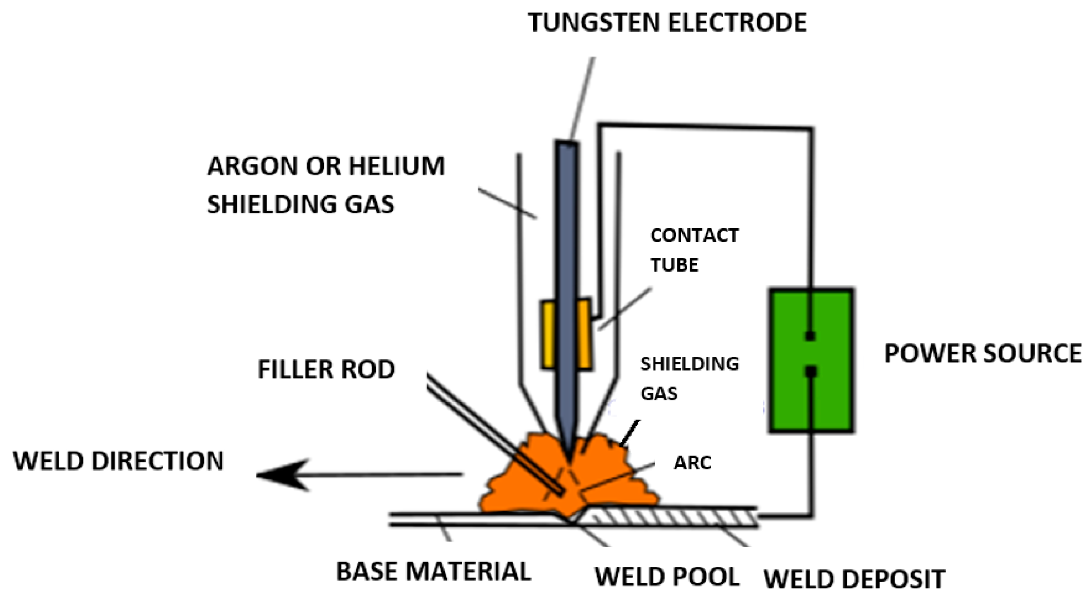
2. TIG Welding Process

The tungsten inert gas (TIG) welding process produces welds with a non-consumable tungsten electrode. During direct current (DC) welding, the electrodes used are usually made of pure tungsten. Thoriated tungsten which contains thorium oxide in the range of 1% to 4% is used to improve arc ignition. Other additives such as lanthanum oxide and cerium oxide have been identified as giving improved performance in terms of arc starting and lower electrode consumption. Because the welding current has a relation with the electrode diameter and the tip angle, it is important to select this parameter in relation to current and tip angle. Therefore, the lower the current, the smaller the electrode diameter and tip angle. In alternating current (AC) welding, since the electrode operates at a much higher temperature, tungsten with zirconia is added to reduce electrode erosion.
In the TIG welding process, the arc is formed between a pointed tungsten electrode and the workpiece in an inert atmosphere of argon (Ar), helium (He) or an Ar–He mixture. The process uses a power source, a shielding gas and a TIG torch. [10]. It is important to note, however, that although the electrode, in theory, is not consumed, control must consider the deterioration of the sharpened tip that occurs due to contamination when the tip comes into contact with the material during the arc ignition. Additionally, small projections of the melted material impact on the tip, contaminating it and influencing the weld quality. This process leads to consumption of the electrode, especially in the case of welding of carbon steels. It is thus important to sharpen the electrode in this situation.
Depending on the required weld preparation and the workpiece thickness, it is possible to work with or without filler. The filler can be introduced manually or automatically depending on the type of process selected. The process itself can be manual, partly mechanized, fully mechanized or automatic.
Filler is used when welding together metals with high melting points to prevent cracking. In addition, highly corrosive resistant alloys when welded to thicker wall material require a filler wire. Finally, when dissimilar alloys are being joined a filler wire is needed. Metals with a thickness of more than 6 mm require the use of filler wire during welding with TIG welding process.
The power is fed from the power source, down the contact tube and is delivered to a tungsten electrode and an electric arc is then created between the tungsten electrode and the workpiece. The tungsten and the welding zone are protected from the surrounding air by a shielding gas to prevent oxidation or contamination from the atmosphere. The electric arc can produce temperatures up to 19,400 °C and this heat can be a much-focused local heat in the TIG welding process. The weld pool can be used to join the base metal with or without filler material [11,12]. Figure 2 shows a schematic diagram of the TIG welding process incorporated with the filler rod.

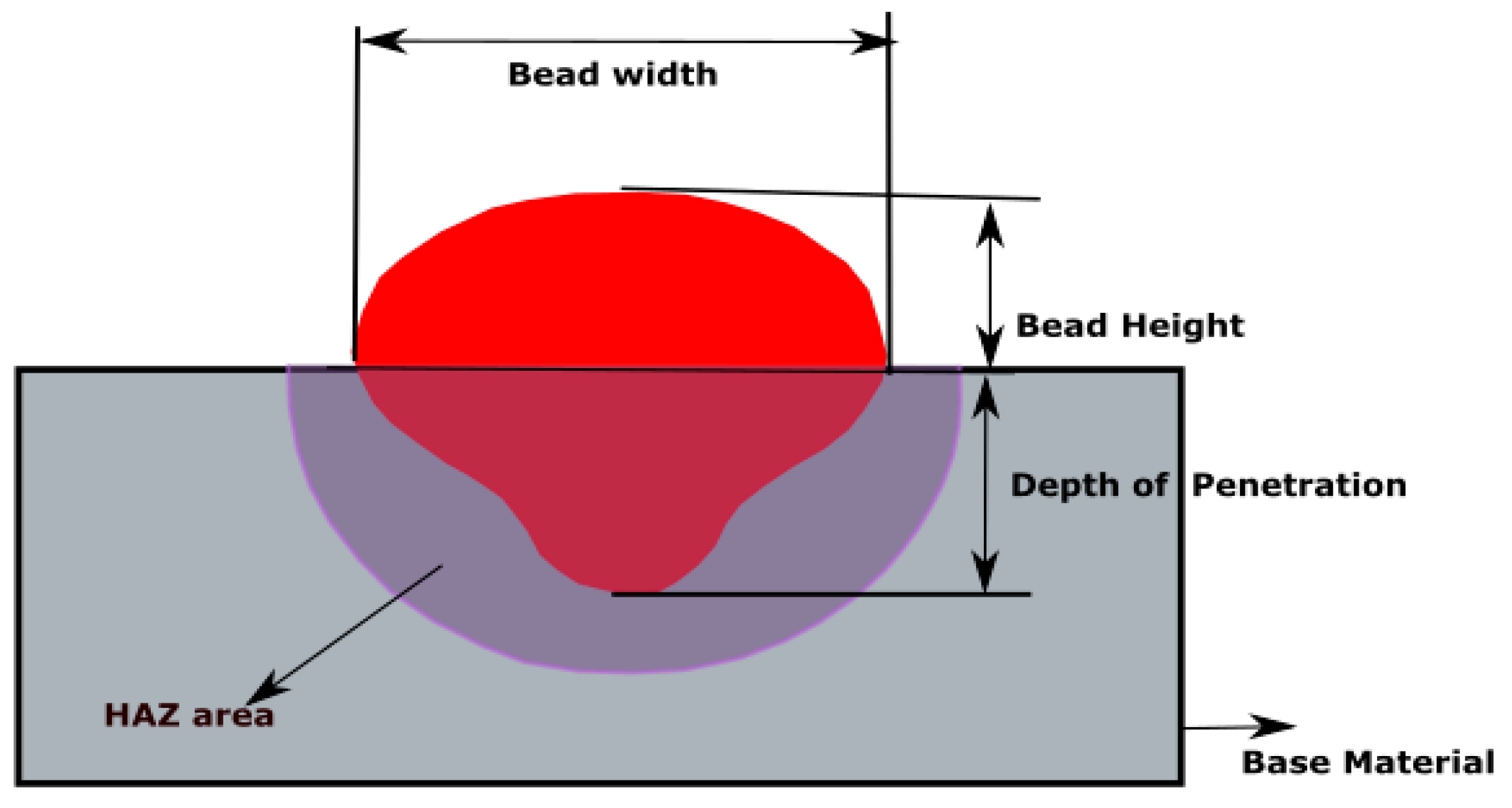
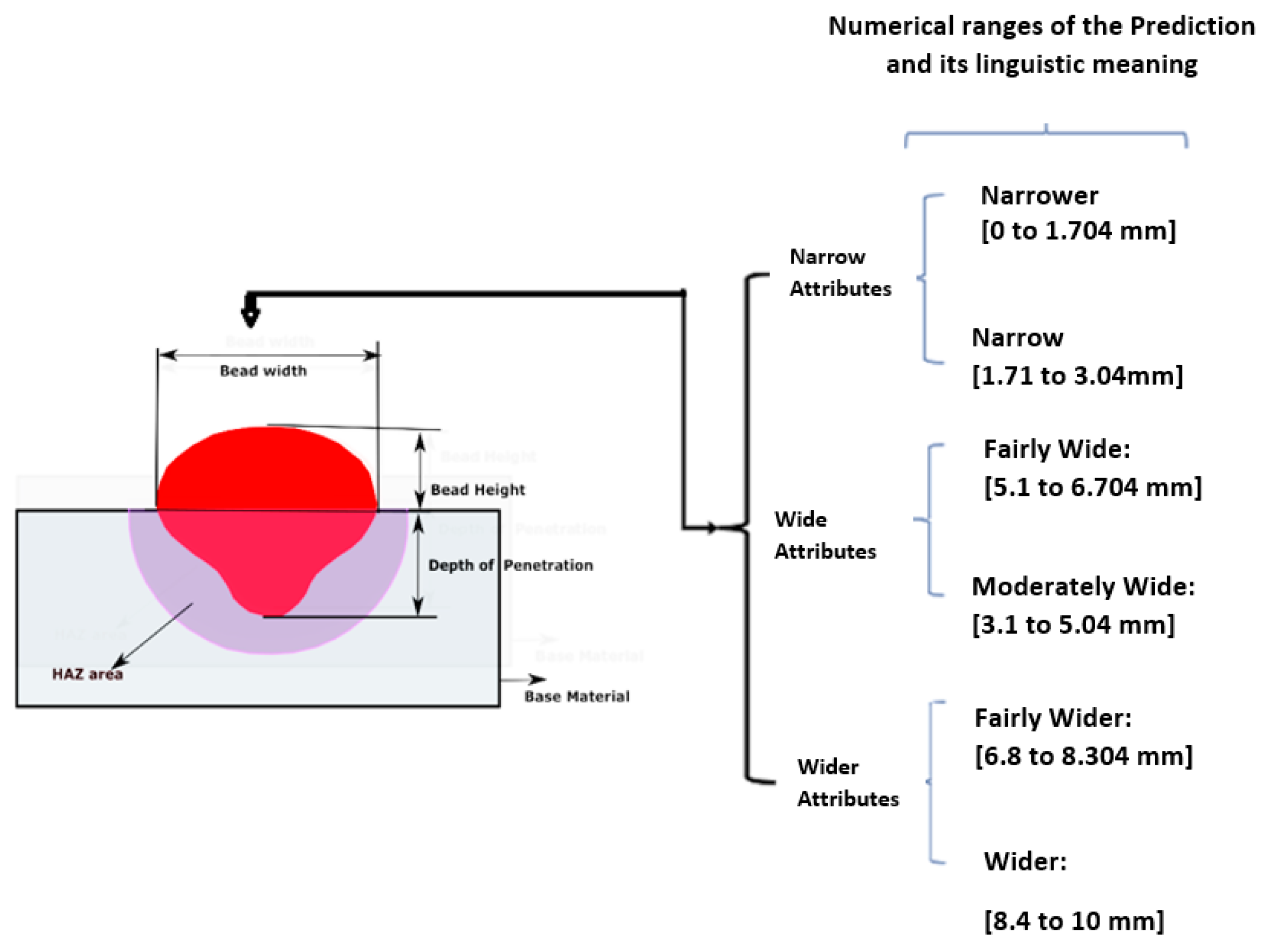
Characteristics of Weld Bead Geometry

Quality is very vital in the welding process and it is important to note that the weld bead plays a major role in achieving the desired quality. The quality of the weld bead geometry and configuration are controlled by various welding process input parameters such as current, voltage and welding speed [13]. Liquid weld metal solidification during welding results in interfacial tensions that usually determine the final bead geometry [14]. The mechanical properties of the weld, which are an important factor in all welded structures, are also influenced by the weld bead geometry [15].
The main defects that occur in the bead geometry during welding are high heat-affected zone (HAZ) width, high fusion width, excess bead height and lack of penetration. Lack of penetration directly affects the strength and load-bearing capacity of the welded joint. Additionally, lack of penetration increases the stress in the weld joint, thereby resulting in crack propagation which affects the fatigue life of the weld joint [16].
Weld bead geometry is illustrated in Figure 3 showing the depth of fusion, which is the distance that fusion extends into the base material and the bead width, which is the maximum width of the deposited weld metal. Bead height or reinforcement height is the bead height above the surface of the plate. The heat-affected zone is the non-melted area that experiences changes in material properties due to exposure to the welding heat.

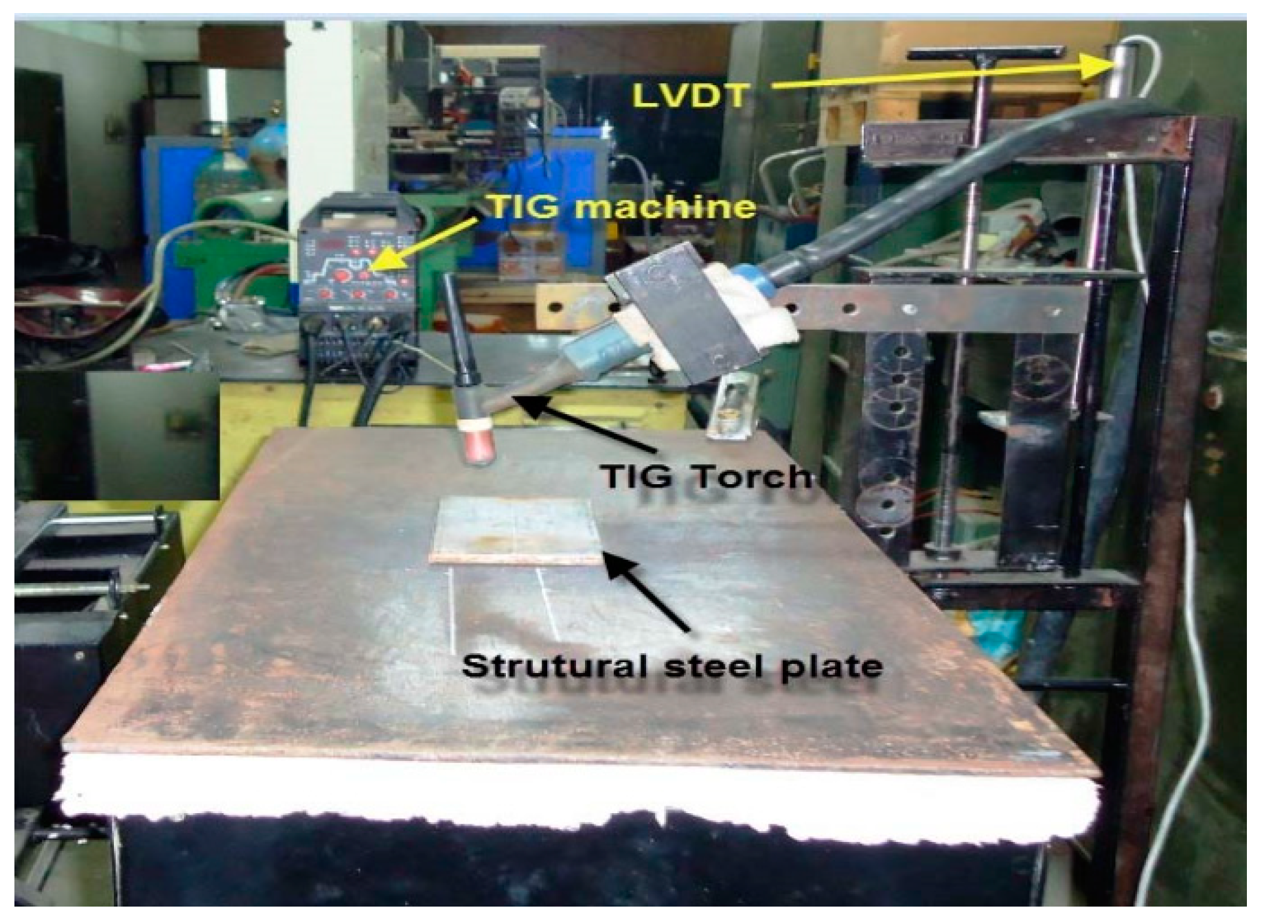
3. Simulation Experiments

This section presents the process for simulation experiments using 27 sets of experimental data. Hybrid fuzzy deep neural learning is applied in the simulation process. The section is divided into two main subsections with further subsections. Section 3.1 presents the system modeling, its mathematical logic and how the control variables and the expected output were measured using fuzzy mathematics. Fuzzy mathematics is the area of mathematics that relates to fuzzy sets and fuzzy logic. Section 3.2 presents the objective evaluation of the proposed system using 27 experiments.

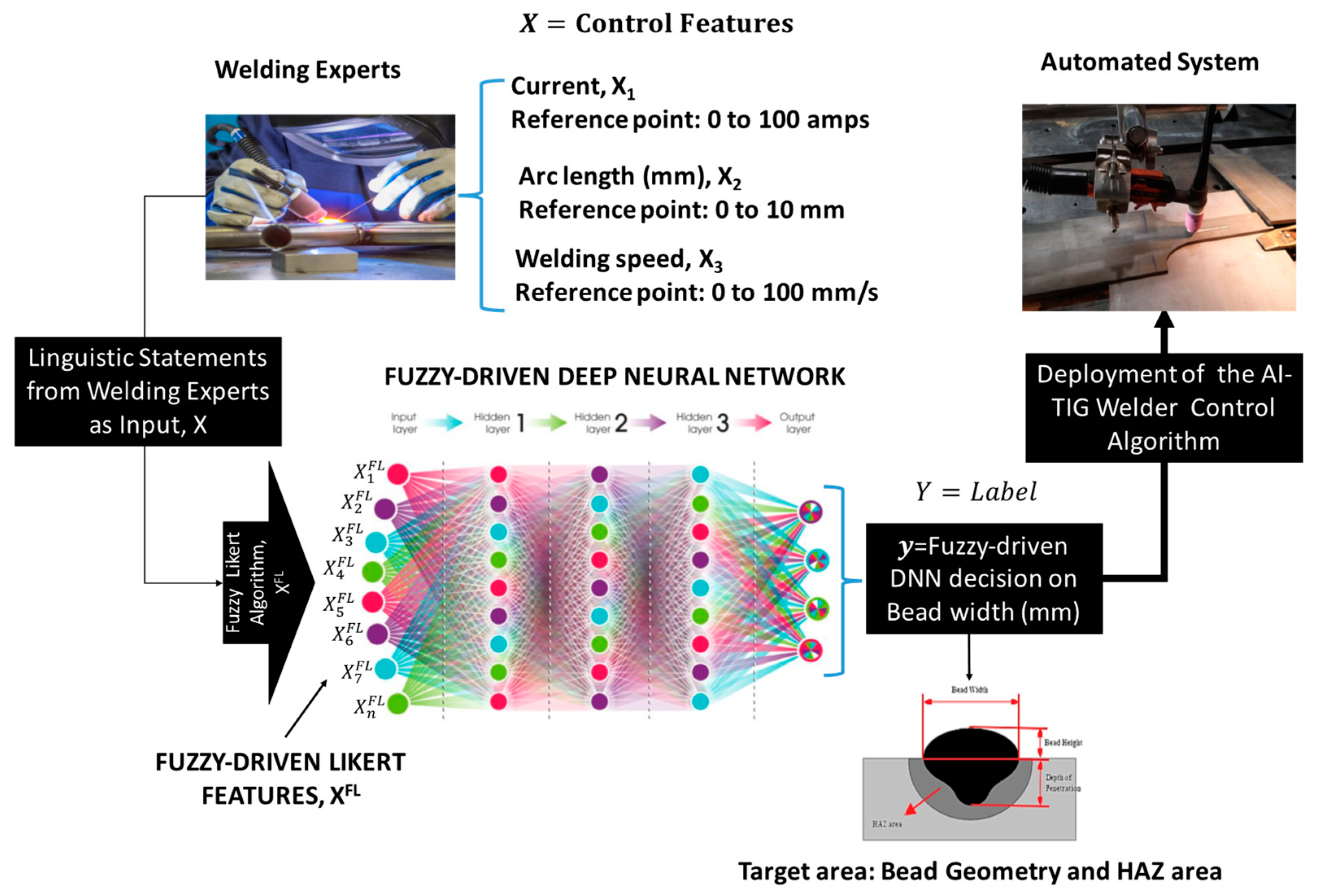
3.1. Building the AI TIG Welding Control Algorithm and Datasets

3.1.1. Feature Selection and Measurement using a Fuzzy Mathematical Technique

Methodologically, the proposed AI TIG welding algorithm is a hybrid deep learning AI technique. It is based on a hybridization of the mathematics of fuzzy logic and the learning capability of deep neural networks (DNN). In the pioneering work of Zadeh [17], fuzzy logic was introduced as an attempt to overcome weaknesses in Boolean logical thinking. It provides a mathematical framework to compute with words based on “degrees of truth” rather than the usual “true or false” (1 or 0) Boolean logic on which the modern computer is based. Fuzzy logic includes 0 and 1 as extreme cases of truth but it also includes the various states of truth in between so that, for example, the result of a comparison between two things could not be “tall” or “short” but “somehow tall” and the height can be quantified using a mathematical curve called a membership function (MF). Therefore, the fuzzy inference processes allow the modeling engineer to generate rule-based control structures as illustrated in Figure 4.
Using the welding process as a case, as shown in Figure 4, the fuzzy inference system consists of three subsystems: the fuzzifier, the rule inference engine and the defuzzifier. The task of the Fuzzifier is to take the expert natural language about the welding process and transform it into fuzzy values using an MF mathematical curve.
Let us assume the following responses: “when the welding speed is very high…,” “when the welding speed is very low….,” “the bead width is narrow.” For us to know to what degree is the bead width narrow or the welding speed very low or very high, it is at the fuzzification process where the system assigns these quantitative weights to incoming data to determine its degree of truth within a universe of discourse (e.g., 0 to 100 mm/s) speed range) on a fuzzy scale using the mathematical curves as depicted in the illustration with “Data 1, Data 2 and Data n passing through the membership function curves.
The task of the rule inference engine is to map a response argument to its expected reality (consequence) using IF...THEN logic. When a condition, for example, is met, the inference engine produces a result sent to the defuzzifier as an input. It is then transformed back to the human language which was initially taken into the system. In this way, both the welder and non-welders can understand the system behavior to influence the environment it observes.
In summary, fuzzy logic is essentially a means to develop human-like capabilities for an AI algorithm that are closer to the way the human brain works. It provides a mathematical framework to model with words and sentences as humans do. In doing so, it helps humans to aggregate data and forms several partial truths which can be aggregated further into higher truths, which, in turn, when certain thresholds or conditions are exceeded, cause certain further results such as motor reaction. By incorporating this knowledge-based AI technique into DNN models, an explainable rule-based structure can be realized in DNN algorithms to alleviate the problems of strictly trading off interpretability for accuracy during the system modeling [18].
In this work, the hybrid fuzzy-DNN technique is necessary for AI TIG Welding system modeling for two reasons. Firstly, because the goal of this work is to develop a system where a human welder can interpret the algorithm decision to make further decisions, and secondly, DNN is a deterministic algorithm that does not account for uncertainties, imprecision, vagueness and ambiguities in the data. The data we have at hand in modeling the system is human data (i.e., data extracted from a welder). This human data has inherent imprecisions, ambiguities and vagueness. The advantage of fuzzy logic is that it has the capability to model this kind of data. Therefore, incorporating fuzzy logic into the system modeling of a neural deep neural network algorithm helps to manage these imprecisions, ambiguities, vagueness and fuzziness [18].
Buah, Linnanen and Wu [4] showed that when DNN, fuzzy logic and Likert scale measurement techniques are combined, it can lead to an architecture called a fuzzy logic-based Likert Inference engine that can create a high dimensional data space for big augmented data to be extracted to augment small human linguistic statements. This data can be used to train a fuzzy-driven DNN algorithm to achieve results closer to the state-of-the-accuracy in DNN. Building on this prior work, this hybrid fuzzy-DNN architecture combined with Likert capability is the main technique that informed the proposed AI TIG Welding algorithm as illustrated in the process model in Figure 5.
Figure 5 illustrates the AI TIG welding algorithm that was built using three control features: X1 as current (I), X2 as arc length and X3 as welding speed. The control parameters are used to predict weld bead width. Table 1 shows the scale ranges used in the system modeling for each parameter.
As illustrated in Figure 5, after defining the parameter ranges, the next step is learning about the control parameters and their theoretical association with the expected output from welding “experts”. To accomplish this, literature was reviewed, and 13 expert-level rules were extracted. The rules are presented in Table 2.
The model architecture is a hybrid fuzzy–DNN model, hence big data is needed to build the model. The 13 expert-level rules are inadequate to train the deep neural network in the architecture. To manage this problem, we built on the work of Buah et al. [4]. and the X values were passed through a classifier called a fuzzy logic-based Likert algorithm as illustrated in Figure 6.
The strength of the fuzzy logic-based Likert algorithm is that it helps to re-scale the raw data X from the human expert on a psychometric scale using traditional Likert scaling, which is then transformed into a fuzzy-driven feature denoted as X F L as depicted in Figure 6. This is the engine for transforming an input variable X to obtain its fuzzy representations called fuzzy-driven Likert features, XFL.
This transformation creates a data space with interval details so that additional data can be collected via data augmentation for training the fuzzy-driven DNN model as shown in Figure 5.
Mathematically, it is expressed as in Equation (1):
X F L = f   ( X )
where X F L is the target and X   is the predictor of the target. So, the goal is to find a function, f   that maps X   and X F L using fuzzy logical rules. Using a 6-point Likert scale, six fuzzy rules were defined to model the fuzzy Likert Inference engine. The extreme ends of the rule are as follows:
Rule 1: If X is Very Low THEN It is corresponding X F L is also Very Low;
Rule 2: If X is Low THEN It is corresponding X F L is also Low;
Rule 3: If X is Medium Low THEN It is corresponding X F L is also Medium Low;
Rule 4: If X is Medium High THEN It is corresponding X F L is Medium High;
Rule 5: If X is High THEN It is corresponding X F L is High;
Rule 6: If X is Very High THEN It is corresponding X F L is Very High.
Having defined the rule function f ( X ) that maps X and X F L , the fuzzy logic-based Likert algorithm was built using the information in Table 3.
As indicated in Table 3, X   was modelled with a 6-point Likert scale and   X F L was modelled with a six-level fuzzy membership function.
The fuzzy logic-based Likert algorithm was then applied to the rules in Table 4 to estimate their system boundaries (maximum and minimum data space). This technique helped re-write the experts rule as shown with an example using Rule 1 in Table 4.
Data augmentation was then carried between the data space of the control parameters. A big experimental dataset amounting to 24,012 training datasets was then extracted to train a fuzzy-driven DNN model as indicated in Figure 5. The idea of data augmentation is that many application domains do not have access to big data as in this case. Therefore, in machine learning, data augmentation is a form of data space solution to the problem of limited data. It encompasses a suite of techniques that enhance the size and quality of training datasets such that better deep learning models can be built [19]. As indicated in Table 4, no data augmentation was performed on the target behavior (weld bead) but rather the mean score of its system boundary is used as labels for the augmented features of the control variables. This was done to mitigate the model vulnerability to the course of dimensionality. With this understanding, the next section presents the training phase of the fuzzy-driven DNN model with the X F L big data features extracted using the data augmentation technique.

3.1.2. Training, Validating and Testing the Fuzzy-Driven DNN Model

As shown in the AI TIG Welding process model in Figure 5, after the fuzzy-driven Likert features X F L have been obtained for all the control variables and their corresponding labels, the next step is training the fuzzy-driven DNN model. The DNN model was implemented using the Keras deep learning library with Google TensorFlow backend using the Python language. Table 5 shows the experimental setting and model architecture.
As indicated in the experimental setting in Table 5, the proposed AI TIG Welding algorithm was built using neural networks and ReLU as an activation function. The expected output is theoretically in three classes but to capture more detailed information about the class labels, it was mathematically sub-divided into six subclasses using fuzzy mathematics, as shown in Figure 7, in line with Table 3.
The model parameters were tuned (optimized) using stochastic gradient descent. Dropout regularization technique was applied to the modeling to prevent the model from over-fitting into the training data since over-fitting affects the model’s performance in generalizing to unseen cases. As indicated in the experimental setting, the algorithm was not built using a pre-trained model; it was trained from scratch. During the training, the model was monitored in addition to making necessary manual stops and the model’s weights were recorded. In the experiment setting, the model was trained and validated with 24,000 experimental big data using 60/40 rules. Using this data split rule, the algorithm randomly used about 14,407 training datasets for training and 9593 for validation. Running the simulation at 176 epochs with a batch size of 122, we obtained a validation accuracy of 95.30%. To offer an objective evaluation of the model, we tested the model with independent data using a TIG process for a real-life experiment shared by Narang [20]. The next section gives a brief description of the experiment and reports the results that emerged when the model was applied to independent data.

3.2. Objective Evaluation of the AI TIG Welding Algorithm

Experiment: A structural steel specimen was welded with TIG welding processes using direct current straight polarity (DCSP), which was integrated with an arc image magnifying system. The length, width and thickness of the mild steel plates used for the experiments were 180 mm, 65 mm and 8 mm. The structural steel plates were cleaned properly to avoid unwanted scaling that can cause weld defects. During the welding process, shielding gas flow rate and diameter of the TIG electrode were kept constant. The chemical composition of the structural steel is given in Table 6.
The experimental setup of the TIG welding procedure integrated with a linear variable displacement transformer (LVDT) is illustrated in Figure 8. The LVDT was used during the experiments to set the gap between the electrode tip and workpiece. Trial runs were undertaken for the bead-on-plate welds to set the levels of three welding inputs of the process: welding current, traverse speed and arc length. In all, 27 test experiments of bead-on-plate welds were carried out and the results are shown in Table 7. Figure 9 shows the polished and etched TIG weldment cross-sections with different process parameters.
To obtain the same data structure used in modeling the AI TIG Welding algorithm, we pre-processed the bead width with the fuzzy logic-based Likert Inference engine in Figure 6 to obtain fuzzy Likert labels within the six classes in Table 3. The AI TIG Welding algorithm was then queried with the 27 unseen experiments. After approximately five seconds of running the simulation, the simulation results presented in Table 8 were obtained.

4. Result and Discussion

In this paper, the objective was to design an artificial intelligence (AI) TIG Welding algorithm to enhance the capability of the human welder to select appropriate input parameters to achieve good welding quality in the welding process. Using current, arc length and welding speed as case features (control variables), an AI-powered TIG Welding algorithm based on the architecture of a hybrid fuzzy deep neural network algorithm was trained. To offer an objective evaluation of the model, it was tested with experimental data from 27 welds. After training and validation, a validation accuracy of 95.30% was obtained by the AI-powered TIG welding architecture. The model was then empirically tested with new test data. Running the test simulation on the 27 real-life experimental data, we obtained the results in Table 6. As shown in the experimental results, the AI TIG welding algorithm exhibited 92.59% predictive accuracy. Out of 27 targets, it predicted 25 correctly with two mistakes (Experiments 18 and 19). As shown in the experimental results, the algorithm gave a hint on the maximum and minimum control range in which the human welder can operate to obtain the desired output. For example, using Experiment 1 as a case, in reference to Table 3, the algorithm suggested that if the current is regulated within 51 to 67.04 A and the arc length is selected within 1.71 to 3.04 mm and the welding speed is set up to a maximum of 17.04 mm/s or less, a moderately high weld bead width of approximately 5.1 to 6.704 can be achieved. This prediction is consistent with the real-life case in the experiment in Table 6, where a current of 55 A was applied, and 2 mm arc length and 15 mm/s welding speed were set as control parameters. As indicated in the real-life case, a weld bead of 5.46 mm was recorded in the experiment, which is within the predictive range of the algorithm. This performance demonstrates the feasibility of our proposed method in supporting the human welder in automatic selection of control parameters to obtain the desired weld bead without going through a time-consuming trial-and-error approach.
In future work, the aim is to test the system with more experimental cases and expand its knowledge development to cover the depth of penetration, depth of the heat-affected zone (HAZ) and the width of the HAZ. The model should be tested in different domains of welding on best practices to improve the knowledge base of the proposed system to progress the field.

Author Contributions

M.A.K. performed the investigations, analyzed the data, and wrote the manuscript; E.B. ran the simulation test; H.H. supervised the investigation. G.K.A. discussed, edited and reviewed the manuscript. All authors have read and agreed to the published version of the manuscript.

Funding

This research received no external funding.

Acknowledgments

This work was supported by Strategic Research Council through the Academy of Finland within the project Manufacturing 4.0—Strategies for Technological, Economical, Educational and Social Policy Adoption. The authors wish to thank Narang et al. at the Mechanical and Industrial Engineering Department, Indian Institute of Technology, Roorkee for the data provided. My profound thanks go to Dr. Muyiwa Olabode for his support. The support of colleagues at the School of Energy Systems, Mechanical Engineering Department, LUT University, Lappeenranta, Finland is acknowledged.

Conflicts of Interest

The authors declare no conflicts of interest.

References

  1. Harold, F.; Giles, Jr.; John, R.; Wagner, Jr. Extrusion: The Definitive Processing Guide, 2nd ed.; Willian Andrews Publications: Wayne, PA, USA, 2014. [Google Scholar]
  2. Yung, W.K.C.; Ralph, B.; Lee, W.B.; Fenn, R. An investigation into welding parameters affecting the tensile properties of titanium welds. J. Mater. Process. Technol. 1997, 63, 759–764. [Google Scholar] [CrossRef]
  3. Dutta, P.; Pratihar, D.K. Modeling of TIG welding process using conventional regression analysis and neural network-based approaches. J. Mater. Process. Technol. 2007, 184, 56–68. [Google Scholar] [CrossRef]
  4. Buah, E.; Linnanen, L.; Wu, H. Emotional responses to energy projects: A new method for modeling and prediction beyond self-reported emotion measure. Energy 2020, 190, 116210. [Google Scholar] [CrossRef]
  5. Torrisi, M.; Pollastri, G.; Le, Q. Deep learning methods in protein structure prediction. Comput. Struct. Biotechnol. J. 2020, 521, 436–444. [Google Scholar] [CrossRef]
  6. Deng, L.; Yu, D. Deep Learning: Methods and Applications. Found. Trends Signal Process. 2014, 7, 197–387. [Google Scholar] [CrossRef] [Green Version]
  7. Goodfellow, I. Deep Learning. Book in Preparation for MIT Press. 2016. Available online: http://www.deeplearningbook.org (accessed on 20 March 2020).
  8. Deng, Y.; Bao, F.; Kong., Y.; Ren, Z.; Dai., Q. Deep direct reinforcement learning for financial signal representation and trading. IEEE Trans. Neural Network Learn. Syst. 2017, 28, 653–664. [Google Scholar] [CrossRef] [PubMed]
  9. Deep Learning in Digital Pathology. Available online: http://www.global-engage.com/life-science/deep-learning-in-digital-pathology/ (accessed on 24 March 2020).
  10. The Welding Institute. Available online: https://www.twi-global.com/technical-knowledge/job-knowledge/tungsten-inert-gas-tig-or-gta-welding-006 (accessed on 18 March 2020).
  11. Larry, F.J. Welding Principles and Applications; Cengage Learning: Boston, MA, USA, 2002. [Google Scholar]
  12. Larry, F.J. Welding and Metal Fabrication; Cengage Learning: Boston, MA, USA, 2002. [Google Scholar]
  13. Azar, A.S.; Ås, S.; Akselsen, O.M. Determination of welding heat source parameters from actual bead shape. Comput. Mater. Sci. 2012, 54, 176–182. [Google Scholar] [CrossRef]
  14. Dey, V.; Pratihar, D.K.; Datta, G.; Jha, M.N.; Saha, T.; Bapat, A. Optimization of bead geometry in electron beam welding using a Genetic Algorithm. J. Mater. Process. Technol. 2009, 209, 1151–1157. [Google Scholar] [CrossRef]
  15. Anbarasan, N.; Oyyaravelu, R.; Kuppan, P. Effect of GMAW process parameters on the influence of bead geometry and HAZ area on ASTM A516 grade 70 Low alloy Pressure vessel steel. Int. J. Technol. Chem. Res. 2015, 1, 1–10. [Google Scholar]
  16. Deshmukh, A.; Venkatachalam, G.; Divekar, H.; Saraf, M. Effect of Weld Penetration on Fatigue Life. Procedia Eng. 2014, 97, 783–789. [Google Scholar] [CrossRef] [Green Version]
  17. Zadeh, L. The concept of a linguistic variable and its application to approximate reasoning—II. Inf. Sci. 1975, 8, 301–357. [Google Scholar] [CrossRef]
  18. Bonanno, D.; Nock, K.; Smith, L.; Elmore, P.; Petry, F. An approach to explainable deep learning using fuzzy inference. Next-Generation Analyst V. Proc. SPIE 2017, 10207, 102070D. [Google Scholar]
  19. Shorten, C.; Khoshgoftaar, T.M. A survey on Image Data Augmentation for Deep Learning. J. Big Data 2019, 6, 60. [Google Scholar] [CrossRef]
  20. Narang, H.; Singh, U.; Mahapatra, M.; Jha, P. Prediction of the weld pool geometry of TIG arc welding by using fuzzy logic controller. Int. J. Eng. Sci. Technol. 2011, 3, 77–85. [Google Scholar] [CrossRef] [Green Version]
Figure 1. Illustration of a conventional neural network and deep neural network (DNN) [9].
Metals 10 00451 g001
Figure 2. Schematic diagram of tungsten inert gas (TIG) welding incorporated with a filler rod.
Metals 10 00451 g002
Figure 3. Schematic illustration of bead geometry and heat-affected zone (HAZ) area [13].
Metals 10 00451 g003
Figure 4. Illustration of the inference engine of a fuzzy controller.
Metals 10 00451 g004
Figure 5. Process model of the artificial intelligence (AI) TIG Welding algorithm modeling steps.
Metals 10 00451 g005
Figure 6. Fuzzy logic-based Likert inference.
Metals 10 00451 g006
Figure 7. Number of output nodes of the model: 3 classes with 6 sub-classes.
Metals 10 00451 g007
Figure 8. Experimental set-up of the TIG welding process.
Metals 10 00451 g008
Figure 9. TIG welds polished and etched showing the weldments and HAZ with different process parameters. Current, arc length and traverse speeds are: (a) 55 A, 2 mm, 15 mm/s; (b) 75 A, 2.5 mm 30 mm/s; and (c) 95 A, 3 mm, 45 mm/s, respectively [20].
Metals 10 00451 g009
Table 1. Psychometric and fuzzy scaling for the parameters.
Control ParametersScale Range of Controlled Parameters, X on Psychometric Scale (Likert) Corresponding Fuzzy Scale Range
Current0 to 100 amps0 to 1
Arc length0 to 10 mm0 to 1
Speed0 to 100 mm/s0 to 1
Bead width0 to 10 mm0 to 1
Table 2. Linguistic rules used in designing the fuzzy logic-based Likert algorithm.
Rules and VariablesIF…(Premise)THEN (Conclusion)
ParametersCurrentArc LengthSpeedBead Width
Rule: 1LowDecreaseVery HighNarrow
Rule: 2Very HighDecrease greatlyVery HighWilder
Rule: 3LowIncrease greatlyVery HighFairly Wide
Rule: 4Medium HighDecrease greatlyVery HighNarrow
Rule: 5Very LowDecrease greatlyVery HighNarrower
Rule: 6Very LowIncrease greatlyVery HighFairly Wide
Rule: 7Very HighDecrease greatlyVery LowFairly Wider
Rule: 8Very HighIncrease greatlyVery LowWider
Rule: 9LowDecreaseVery HighFairly Wide
Rule: 10LowIncrease greatlyVery HighFairly Wide
Rule: 11Very HighIncrease greatlyLowWider
Rule: 12Very HighDecrease greatlyLowModerately Wide
Rule: 13LowDecreaseHighNarrower
Table 3. Description of features (Control variables) and labels (Outcome), their Likert values and corresponding fuzzy Likert crisp values for degree of truth.
Features and Labels Linguistic Terms for ParametersFuzzy Likert Range, Likert Value, XCorresponding Fuzzy Range of Fuzzy Likert, XFL
Current (A)
0 to 100 A
Very Low 000–0.1704
Low17.1–30.423.750.171–0.304
Medium Low31.0–50.440.70.31–0.504
Medium High51.0–67.0459.020.51–0.6704
High 68.0–83.0475.520.68–0.8304
Very High 84.0–1001000.84–1
Arc Length (mm)
0 to 10 mm
Decrease greatly 0–1.70400–0.1704
Decrease1.71–3.042.3750.171–0.304
Slightly decrease 3.1–5.044.070.31–0.504
Slightly Increase5.1–6.7045.9020.51–0.6704
Increase6.8–8.3047.5520.68–0.8304
Increase Greatly8.4–10100.84–1
Speed (mm/s)
0 to 100 mm/s
Very Low 000–0.1704
Low17.1–30.423.750.171–0.304
Medium Low31.0–50.440.70.31–0.504
Medium High51.0–67.0459.020.51–0.6704
High 68.0–83.0475.520.68–0.8304
Very High 84.0–1001000.84–1
Bead Width (mm)
0 to 10 mm
Narrower 0–1.70400–0.1704
Narrow1.71–3.042.3750.171–0.304
Fairly Wide3.1–5.044.070.31–0.504
Moderately Wide5.1–6.7045.9020.51–0.6704
Fairly Wide6.8–8.3047.5520.68–0.8304
Wider 8.4–10100.84–1
Table 4. Modified expert rules using a fuzzy Likert algorithm.
Rules and VariablesIf…(Premise)Then (Conclusion)
ParametersCurrentArc LengthSpeedBead Width
Rule:1 → X LowDecreaseVery HighNarrow
Rule:1 → XFL17.1–30.41.71–3.0484.0–100Narrow (2.375)
Table 5. Experimental setting of the proposed DNN-based TIG Welding algorithm.
Learner TypeNeural Networks
Number of output nodes3 classes with 6 sub-classes (see Figure 6 and Table 3)
Loss functionCategorical cross-entropy
Hidden layer8-layer network with 6 hidden layers
Total number of neurons: 188
Maximum number of training iterationsEpochs: 176 and Batch size: 122
Activation functionRectified linear unit (ReLu)
Optimization algorithmStochastic gradient descent
Early stopping ruleManual stopping by observation in loss in generality
Pre-trainingNo pre-trained model. The models were trained from scratch
RegularizationDropout
Dropout was applied to 6th and 7th layer with 0.05 and 0.55, respectively
Dataset for training and validationTraining sample: 14,407
Validation sample: 9593
Data split rule: 60/40
Dataset for testing: objective evaluation27 experiments
Learning rate0.003
Table 6. Chemical composition of the structural steel.
C %Si %Mn %P %S %Ni %Cr %Fe %
0.160.1780.450.180.070.130.01698.84
Table 7. Test data for 27 test experiments of bead-on-plate welds.
Serial Number (S.N)Current (A)Arc Length (mm)Welding Speed (mm/s)Bead Width (mm)Depth of Penetration (mm)Depth of HAZ (mm)Width of HAZ (mm)
1552155.461.591.731.83
2552304.711.251.191.35
3552454.161.041.021.13
4552.5155.771.761.942.20
5552.5304.931.381.331.63
6552.5454.461.181.161.33
7553156.091.912.132.45
8553305.031.421.511.84
9553454.551.231.231.46
10752156.121.992.482.25
11752305.131.391.461.72
12752.5454.591.161.221.39
13752.5156.592.062.652.41
14752.5305.261.501.651.89
15752.5454.851.321.341.57
16753157.072.182.722.79
17753305.451.651.862.02
18753455.161.451.581.79
19952156.652.173.042.7
20952305.381.511.811.94
21952454.751.231.491.52
22952.5157.192.233.322.89
23952.5306.161.631.972.15
24952.5455.21.321.561.75
25953157.642.513.213.15
26953306.311.742.152.70
27953455.111.411.742.16
Table 8. Simulation experiment results when the class labels of the predicted values were compared with the observed values from the laboratory experiment.
S.NObserved Values of Bead Width in LABClass Label of Observed Value in Fuzzy Likert TermsFuzzy Linguistic Terms for Observed Values Predicted Value of Bead Width with the AI TIG WeldingClass Label of Predicted Values in Fuzzy Likert Terms
15.465.1–6.704Fairly wide5.1–6.704Fairly wide
24.713.1–5.04Moderately wide3.1–5.04Moderately wide
34.163.1–5.04Moderately wide3.1–5.04Moderately wide
45.775.1–6.704Fairly wide5.1–6.704Fairly wide
54.933.1–5.04Moderately wide3.1–5.04Moderately wide
64.463.1–5.04Moderately wide3.1–5.04Moderately wide
76.095.1–6.704Fairly wide5.1–6.704Fairly wide
85.033.1–5.04Moderately wide3.1–5.04Moderately wide
94.553.1–5.04Moderately wide3.1–5.04Moderately wide
106.125.1–6.704Fairly wide5.1–6.704Fairly wide
115.135.1–6.704Fairly wide5.1–6.704Fairly wide
124.593.1–5.04Moderately wide3.1–5.04Moderately wide
136.595.1–6.704Fairly wide5.1–6.704Fairly wide
145.265.1–6.704Fairly wide5.1–6.704Fairly wide
154.853.1–5.04Moderately wide3.1–5.04Moderately wide
167.076.8–8.304Fairly wider6.8–8.304Fairly wider
175.455.1–6.704Fairly wide5.1–6.704Fairly wide
185.165.1–6.705Fairly wide3.1–5.04Moderately wide
196.655.1–6.706Fairly wide6.8–8.304Fairly wider
205.385.1–6.704Fairly wide5.1–6.704Fairly wide
214.753.1–5.04Moderately wide3.1–5.04Moderately wide
227.196.8–8.304Fairly wider6.8–8.304Fairly wider
236.165.1–6.704Fairly wide5.1–6.704Fairly wide
245.25.1–6.704Fairly wide5.1–6.704Fairly wide
257.646.8–8.304Fairly wider6.8–8.304Fairly wider
266.315.1–6.704Fairly wide5.1–6.704Fairly wide
275.115.1–6.704Fairly wide5.1–6.704Fairly wide

