Article

Derivation of New Staggered Compact Schemes with Application to Navier-Stokes Equations

Dipartimento di Ingegneria Industriale (DII), Università di Napoli “Federico II”, 80125 Napoli, Italy
*
Author to whom correspondence should be addressed.
Appl. Sci. 2018, 8(7), 1066; https://doi.org/10.3390/app8071066
Submission received: 6 June 2018 / Revised: 19 June 2018 / Accepted: 25 June 2018 / Published: 29 June 2018
(This article belongs to the Section Mechanical Engineering)

Abstract

:
A method is proposed for the derivation of new classes of staggered compact derivative and interpolation operators. The algorithm has its roots in an implicit interpolation theory consistent with compact schemes and reduces to the computation of the required staggered derivatives and interpolated quantities as a combination of nodal values and collocated compact derivatives. The new approach is cost-effective, simplifies the imposition of boundary conditions, and has improved spectral resolution properties, on equal order of accuracy, with respect to classical schemes. The method is applied to incompressible Navier-Stokes equations through the implementation into a staggered flow solver with a fractional step procedure, and tested on classical benchmarks.

1. Introduction

Direct numerical simulation of many complex multi-scale problems, such as turbulence in fluids, requires the use of adequately refined grids to resolve the structure and the dynamics of the smallest scales. However, in many situations the limits of available computing power, both in terms of memory requirements and of integration time, force the choice of the grid to a step size which is at (or even over) the edge of the acceptable resolution. In these situations the physics is described within a few computational nodes and the resolution properties of the discretization are a crucial factor. A similar situation is encountered in Large Eddy Simulation (LES) of turbulence. In this case, the smallest scale resolved by the discretization is deliberately greater than the smallest physical scales having significant energy, since the effects of the latter are modelled through the specification of a suitable subgrid model. In this case, the resolution of the discretization (intended as the number of mesh points required for a given accuracy at a given wave length) is even more important, since the numerical errors have to be small as compared to the subgrid energy contribution.
In these and in many other cases, high-order methods are usually recommended, since they generally provide lower levels of numerical errors for the grids employed. In recent years high order implicit compact schemes have been extensively used for flow problems, as an alternative to high order explicit finite-difference schemes and to spectral (or pseudospectral) schemes. After the 1992 seminal paper by S. K. Lele [1], in which a comprehensive and systematic presentation of compact schemes is reported, they have been extensively used in fluid flow calculations, both in compressible and incompressible cases. Their success is due to several favourable properties which place them in between the flexibility typical of explicit finite difference schemes and the resolution properties of global spectral schemes.
Although the influential paper by Lele is considered as the starting point for the subsequent huge research activity on compact schemes and on their applications, there is a quite interesting production on this subject well before the nineties, whose character is, in some sense, in line with the approaches taken in this paper. Actually, implicit compact derivatives were already used in numerical analysis well before the seventies (cfr. for example [2]); however, their main application was limited to the finite-difference approximation of ordinary differential equations. The fourth-order implicit Nyström formula, known as Simpson’s rule, can indeed be viewed as an application of the classical Padé scheme to a system of first order ordinary differential equations. The first mention in the open literature of the opportunity of using implicit compact formulæ for the numerical approximation of partial differential equations seems to be due to S. Orzsag and M. Israeli [3], who attribute to H. O. Kreiss the suggestion. In that paper, they fully recognized the main favorable characteristics of compact schemes, namely the reduced truncation error (with respect to the analogous explicit formulæ) the reduced width of the stencil, which eases the implementation of boundary conditions, and the low computational cost. The idea of using implicit formulæ for the computation of spatial derivatives can be possibly traced back to the finite difference formulation of some finite element methods based on Hermite cubics, which had growing popularity at that time (see the interesting observation made at p. 59 of ref. [4]).
The authoritative suggestion contained in the review of Orszag and Israeli sparked many studies on the development and test of compact schemes. Almost simultaneously compact schemes were applied with success to the wave equation [5], to parabolic equations [6] and to different nonlinear fluid mechanics problems [7]. In this last paper also the problem of boundary conditions is investigated, and a series of asymmetric formulæ for the boundary is presented. In these early years the focus was not only on the applications of compact schemes, but also on the development of a theoretical framework in which new schemes could be derived. In a series of papers, Rubin and co-workers [8,9,10] firstly estabilished that many compact schemes can be derived by employing the theory of spline interpolation. They showed, for example, that the classical Padé fourth-order formula for first derivative can be obtained by analytically differentiating the cubic spline interpolation, thus recognizing that compact schemes could be derived through a theory of polynomial interpolation in physical space, which has to be necessarily implicit. They also obtained formulæ for second derivatives and for the case of nonuniform mesh, and applied their schemes to a variety of fluid flow problems. Ciment et al. [11] developed the theory of the “Operator Compact Implicit Method”, in which new classes of compact schemes were derived for parabolic problems by applying the compact technique to the full spatial convection-diffusion operator. Adam [12], while investigating the problem of boundary condition closures, proposed also a new method for obtaining a second derivative approximation for interior points through the so-called “explicit elimination”, in which the second derivative is expressed as a function of the values and of the computed set of first derivatives, in a way which shares some similarities with the technique adopted in this paper. Finally, Chang and Shirer [13] introduced for the first time the formulæ for compact interpolation and for compact staggered derivatives in their applications to geostrophic adjustment problem and to the nonlinear two-dimensional vortex-advection problem. In the first application, they also compared the various schemes by computing the discrete dispersion relation of the gravity waves, in an analysis which is practically equivalent to the Fourier analysis of the modified wavenumber, which is now a standard tool for the evaluation of the resolution properties of difference schemes.
The polynomial approach for the derivation of compact schemes has been pursued in further occasions during the past two decades. Chu and Fan [14,15] used the theory of Hermite interpolants, based on first and second derivative data, to obtain the expressions for their so-called CCD schemes, in which both first and second derivatives appear as unknowns in the generic scheme. Coppola and Meola [16] developed a new theory of Local Matched Reconstructions, which generalizes the spline interpolation theory and is more suited to the systematic generation of all the classical collocated compact schemes. In that paper the authors employ this theory also to derive new classes of compact schemes.
In this paper, we present a strategy for the generation of several compact derivatives starting from the computation of a single set of compact schemes. The idea is motivated by the growing interest in the application of compact schemes to Navier-Stokes equations [17,18,19,20,21] and is here applied to a typical incompressible Navier-Stokes solver with a staggered arrangement of the variables. The convective term is discretized by using the skew-symmetric form, which is a mandatory choice for energy-stable simulations in the context of compact-difference schemes. In such a situation, the computation of convective and diffusive terms in the the momentum equation requires the evaluation of staggered derivatives and interpolations of velocity components, together with the collocated second derivative. It will be shown that an efficient and economic way of obtaining all these quantities can be devised, which is based on the computation of a single set of compact derivatives, i.e., through the solution of a single tridiagonal system.
The paper is organized as follows. In Section 2 the Hermitian interpolation theory is presented for fourth-order schemes, and then extended to high-order methods. The characteristics of the novel schemes are analyzed in Section 3, while in Section 4 the implementation into an incompressible Navier-Stokes algorithm is discussed. Section 5 presents numerical results. Concluding remarks are given in Section 6.

2. Problem Formulation and Derivation of New Compact Schemes

In this section, we present the procedure for obtaining the whole set of compact formulæ needed in a typical staggered Navier-Stokes solver, starting from the computation of a single set of collocated compact derivatives. We will firstly describe how to construct the formulæby employing the classical fourth-order Padé scheme as a starting point. The extension to higher-order schemes is straightforward and will be presented in Section 2.4. Moreover, the procedure will be illustrated with reference to a uniform mesh; the extension to non-uniform meshes is also in principle straightforward, but will be not considered here. Hereinafter, when referring to derivatives, we will use the terms collocated and staggered to denote that the derivatives are computed in the same location, or shifted with respect to the original data set respectively.
Let us assume that the dependent variable f x is discretized on an uniform mesh x j = j h with j = 0 N and h = L / N . For interior points, the classical fourth-order Padé scheme reads:
1 6 f j 1 + 2 3 f j + 1 6 f j + 1 = f j + 1 f j 1 2 h ,
with truncation error ( 1 / 180 ) h 4 f V . This equation is a typical choice for high-order compact approximations of the first derivative on a collocated mesh. The set of nodal derivatives is obtained by solving a tridiagonal linear system, for which standard highly-efficient methods are available. The computational cost associated to this scheme, for a system of N equations, can be roughly estimated to be 10 N floating point operations. This value is obtained by summing the cost of the computation of the right-hand side ( 2 N ) to that of a standard Thomas solver for the tridiagonal system ( 8 N , 22]). Being a central method, the Padé scheme is free of numerical dissipation when employed in linear problems with periodic boundary conditions. In the non-periodic case it requires the specification of one non-symmetric scheme for each boundary node, in the case in which the dependent variable naturally falls on the boundary. In a typical staggered Navier-Stokes solver, however, this scheme cannot be used, since the quantities known at nodes x j have to be either interpolated or differentiated at the staggered locations x j + 1 / 2 = ( x j + x j + 1 ) / 2 . For this problem, the analogous staggered fourth order compact scheme is given by:
1 24 f j 1 / 2 + 11 12 f j + 1 / 2 + 1 24 f j + 3 / 2 = f j + 1 f j h ,
with truncation error ( 17 / 5760 ) h 4 f V . Please note that in Equations (1) and (2), as well as in all the other classical compact formulæ considered in the following, the convention that the left-hand side coefficients sum to one is assumed. This convention is alternative to the common choice for which the coefficient of the central term ( f j or f j + 1 / 2 ) equals to one; it has been adopted with the aim of obtaining a fair comparison of the truncation errors among the various compact and explicit formulæ considered in this work. Equation (2) is again a centred non-dissipative scheme. Again, one non-symmetric scheme is required for each boundary node when the dependent variable falls on the boundary. The computational cost associated to this scheme can be again estimated to be 10 N operations.
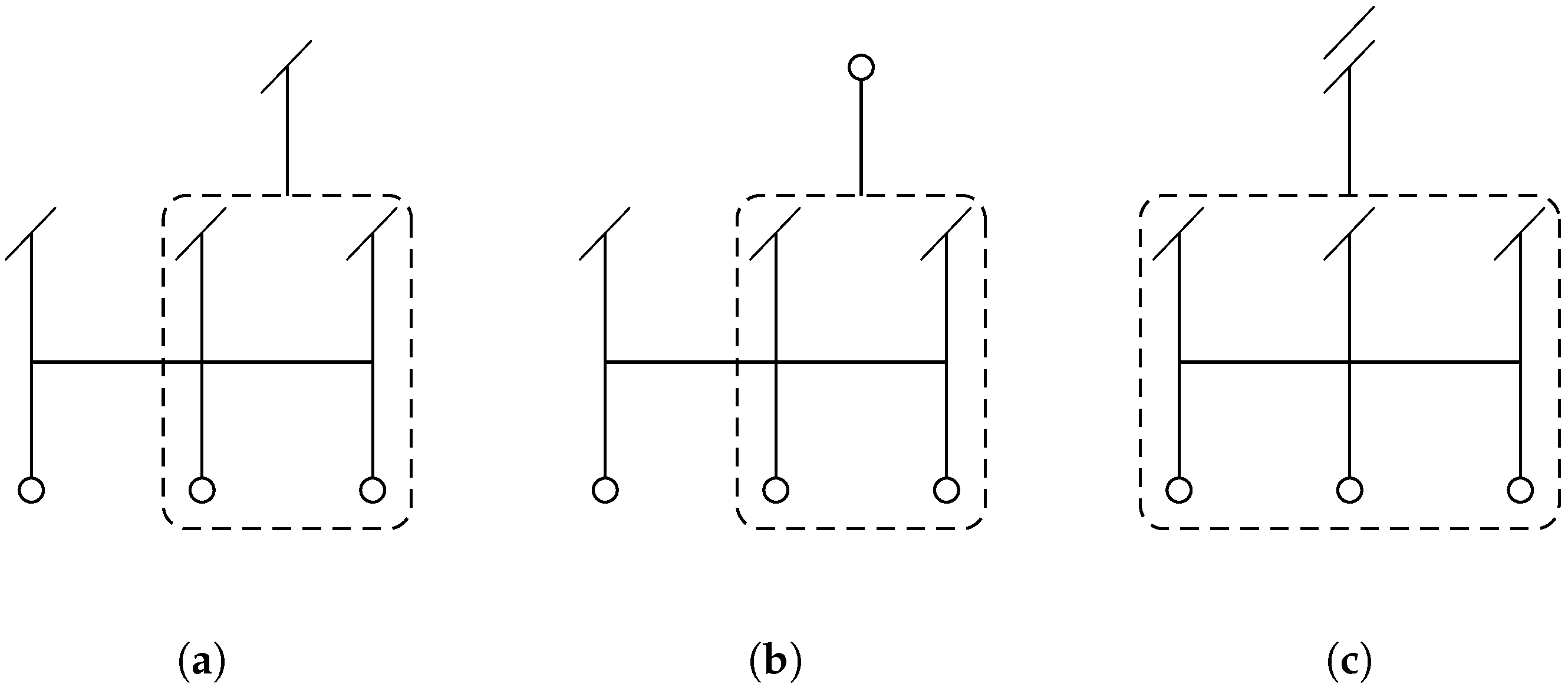
In what follows, each scheme will be referred to by a short acronym of the form n1L1L2-Dn2, where n 1 is an integer equal to the formal order of accuracy of the scheme, L 1 is either C or S for collocated and staggered schemes respectively, L 2 is E, C, or H for explicit, compact, and proposed Hermitian schemes, and n 2 is the order of derivation of the left-hand side of the scheme (0 for interpolation schemes). For instance, Equations (1) and (2) are referred to by the acronyms 4CC-D1 and 4SC-D1 respectively. Moreover, it will be useful to refer to a graphical representation of the various numerical schemes that will be introduced; each variable appearing in the finite-difference formula is depicted with a different symbol, depending on its order of derivation, and in a different position with respect to the stencil, depending on its role in the scheme. The explicit data f j are depicted as small circles, while first and successive derivatives are denoted by a corresponding number of inclined dashes. If a variable is a known quantity in the formula, its position in the graphical representation falls within the lower part, below the horizontal line representing the mesh. If it is an unknown, it is positioned above the mesh, in the upper part of the sketch.
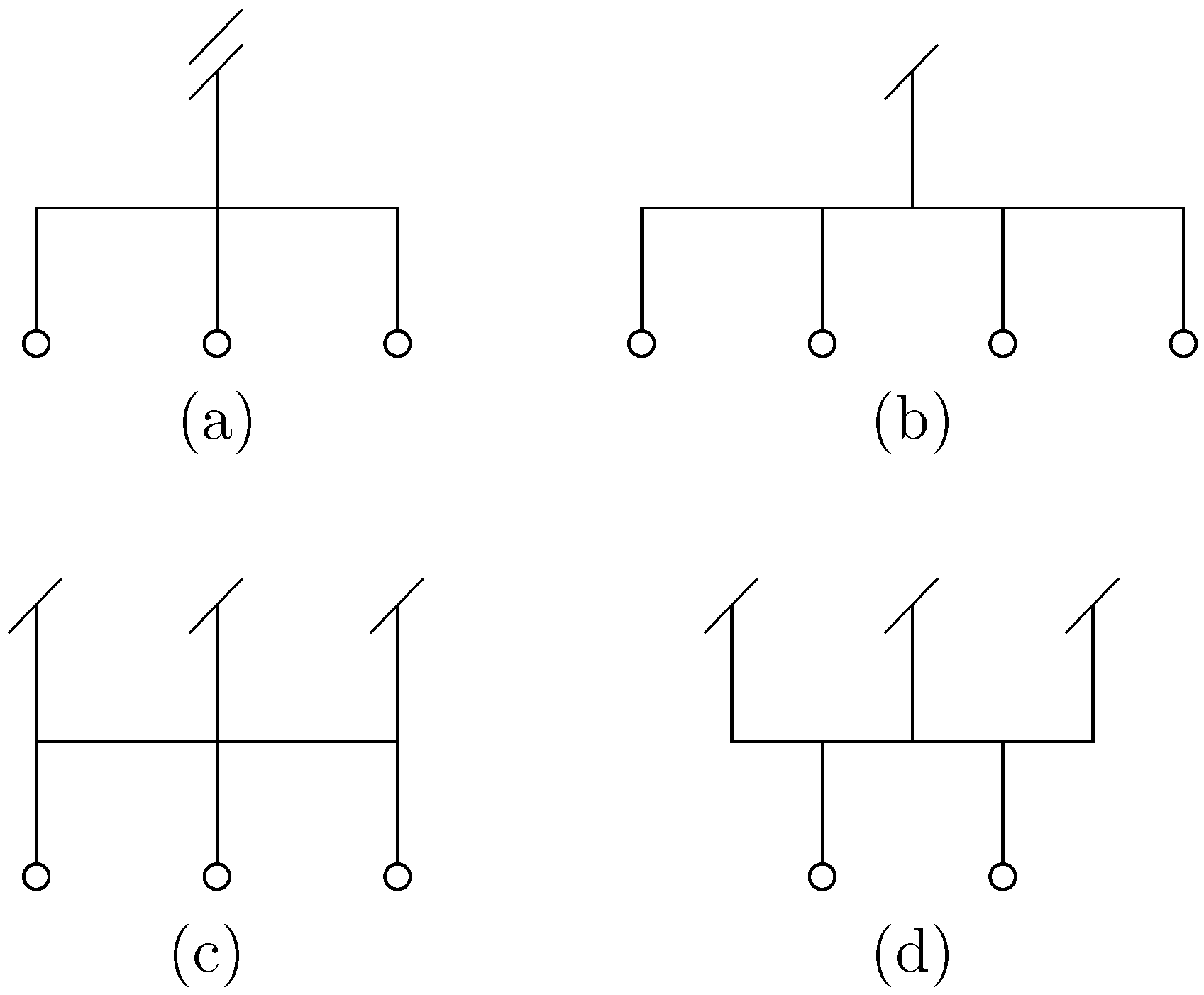
In Figure 1, some examples are reported for different classical schemes, both explicit and compact. The weights appearing in the numerical formula can be also reported in the sketch as associated to each variable. When such weights are omitted, it is assumed that the drawing represents the (unique) maximum-order scheme attainable on that stencil. Figure 1a represents the classical second-order explicit scheme for the second derivative, while Figure 1b depicts the staggered explicit fourth-order scheme (4SE-D1) given by:
f j + 1 / 2 = 9 8 f j + 1 f j h 1 8 f j + 2 f j 1 3 h .
Also, Equation (1) is represented in Figure 1c, Equation (2) in Figure 1d.
The procedure proposed in this paper is based on the observation that the Padé scheme here considered, Equation (1), can be obtained (as virtually all compact schemes) by evaluating the analytical derivative at the node x j of a local polynomial reconstruction P j for the unknown function f, as it is done for explicit finite difference formulæ. In the case of compact schemes, the implicit character of the relation between the set of grid nodes derivatives and the nodal values f j , suggests that local polynomial representations of the unknown function f relative to adjacent nodes have to be linked by implicit relations. This representation is in general not unique. It is well known, for instance, that in the particular case of the Padé scheme, the classical third-degree cubic spline gives a consistent interpolation, in the sense that its analytical first derivative at node x j returns Equation (1) [10]. In what follows, we will consider a different set of local interpolations which is consistent with the compact scheme in Equation (1). This set is given by the class of polynomials P j , of degree four, determined by imposing the explicit conditions
P j ( x k ) = f k k = j 1 , j , j + 1 ,
together with the implicit conditions
P j ( x j + 1 ) = P j + 1 ( x j + 1 ) ,
P j ( x j 1 ) = P j 1 ( x j 1 ) .
It is easy to verify that the derivative at node x j of the local polynomial expansion P j , which can be assumed to be defined on the interval x j 1 , x j + 1 , furnishes again Equation (1). This approach was exploited in [16] in order to give an alternative derivation of many of the classical compact formulæ. New interpolation procedures were also investigated in that paper, based on the enforcement of more general implicit conditions. The theory developed therein generalizes the classical spline interpolation, and led to new classes of compact–type schemes.
In this paper, we adopt a slightly different standpoint, in which the implicit polynomial approach is not employed as a tool to justify the derivation of Equation (1), or of similar collocated formulæ. Here, the set of local polynomial approximations P j consistent with Equation (1) is used as the basis for the calculation of all the compact approximations needed in a staggered Navier-Stokes algorithm, which is typically constituted by staggered interpolations and first derivatives, and by collocated second derivatives.
The polynomials P j determined by the conditions of Equations (4)–(6) can be conveniently obtained by performing an Hermitian interpolation of the grid values f j and of the derivatives f j , once these last ones have been obtained by solving the tridiagonal system associated to Equation (1). Of course, this last procedure is equivalent to the one outlined above, in which the explicit and implicit conditions in Equations (4)–(6) for the whole set of local polynomials P j j are enforced. Please note that in the present procedure we assume that the values f j are assigned, while the compact scheme in Equation (1) is used to get a larger number of information, which is then exploited to feed the higher-degree Hermitian interpolation. The computation of the polynomial functions P j would allow one to have a complete local approximation of the function f in the interval x j 1 , x j + 1 . Any information on the interpolated values, or on first or higher-order derivatives, at any point near x j can be obtained analytically by evaluating P j or its derivatives at the selected point. The evaluation of P j and of its first derivative at staggered points and the evaluation of P j at grid points, leads to new compact-type formulæ, which can be obtained explicitly, once the single compact scheme in Equation (1) has been computed.

2.1. Schemes for Staggered First Derivative

The numerical formulæ for the first derivatives f j + 1 / 2 , at staggered grid points x j + 1 / 2 , based on the Hermite polynomial P j , can be directly evaluated as a linear combination of nodal values f k and nodal first derivatives f k for k = j 1 , j , j + 1 . Since the six values f j 1 , f j , f j + 1 and f j 1 , f j , f j + 1 , are related by Equation (1), only five of them can be chosen independently for the construction of the the fourth-degree polynomial P j . Although any choice of five data among them is equivalent, for what concerns the evaluation of first derivative at the staggered point x i + 1 / 2 , the selection of the values f j 1 , f j , f j + 1 and f j , f j + 1 is particularly convenient, since for this set of data the coefficient of the value f j 1 results to be zero. This is a consequence of the symmetry of the problem: the first derivative at x j + 1 / 2 of the third-degree polynomial fitting the data f j , f j + 1 and f j , f j + 1 is coincident with the derivative at the same point of the whole family of fourth-degree polynomials fitting the same data. This is similar to what happens for a linear interpolation between two points x j and x j + 1 , which shares the same first derivative at x j + 1 / 2 with the whole family of parabolas that fit the same data.
For uniform meshes, the formula to compute the staggered first derivative based on collocated data and first derivatives (4SH-D1, H standing for Hermitian) assumes the simple form:
f j + 1 / 2 = 3 f j + 1 f j 2 h f j + f j + 1 4 .
The combination of Equations (1) and (7) gives a fourth-order scheme for the staggered first derivative at interior points with global truncation error ( 13 / 5760 ) h 4 f V . The standard reference for comparison for this scheme is the staggered fourth order Padé scheme of Equation (2), which has a comparable truncation error, while the explicit scheme of Equation (3) has truncation error ( 9 / 1920 ) h 4 f V . For non-periodic boundary conditions, Equation (1) has to be replaced by suitable non-symmetric compact formulæ at the boundary nodes, while Equation (7) remains unaltered near boundaries. The computational cost of Equation (7) can be estimated to be 5 N . The graphical sketch of the proposed scheme, which is built upon the successive application of Equations (1) and (7), is given in Figure 2a.
A quick inspection of Equations (1) and (7) reveals that both express essentially the same relation between the five values in the sets ( f j 1 , f j , f j + 1 , f j 1 , f j + 1 ) and ( f j , f j + 1 / 2 , f j + 1 , f j , f j + 1 ) respectively, the only difference being the spacing (h in the former, h / 2 in the latter). Nonetheless, the two schemes differ in the crucial choice of known and unknown terms in the aforementioned sets, thus the two corresponding equations are presented separately ([19], cf. Equations (20) and (21)). We take the opportunity to stress that any finite difference formula can be obtained by requesting that a linear combination of the desired nodal values—of derivatives of various orders—be proportional to O ( h p ) , being p the minimum order of accuracy of the scheme. This approach is the most general and easily allows the computation of the coefficients used in several class of unconventional schemes [14,15,23].

2.2. Schemes for Interpolation

The interpolation scheme can be obtained with a procedure similar to that described for staggered first derivative. The evaluation of the local Hermitian polynomial P j at node x j + 1 / 2 gives a consistent approximation of the function value, which is based on a fourth-degree polynomial. However, in this case the procedure produces a non-symmetric formula, which causes the interpolation scheme to be dissipative. To avoid this circumstance, one can derive a symmetric scheme either by taking the arithmetic mean of the two interpolation formulæ given by the polinomials P j and P j + 1 at node x j + 1 / 2 , or by evaluating the interpolation P j ˜ based on the reduced set of values f j , f j + 1 , f j , f j + 1 . The two approaches give respectively the schemes 6SH-D0 and 4SH-D0 (D0 stands for interpolation):
f j + 1 / 2 = 1 128 f j 1 + f j + 2 + 63 128 f j + f j + 1 + 9 h 64 f j f j + 1 ,
f j + 1 / 2 = 1 2 f j + f j + 1 + h 8 f j f j + 1 ,
with global truncation errors ( 1 / 1024 ) h 6 f V I and ( 1 / 384 ) h 4 f I V , when Equation (1) is used for first derivatives at the right hand side of Equations (8) and (9). In the case of interpolation, the third-degree polynomial based on the data f j , f j + 1 , f j , f j + 1 furnishes a fourth-order approximation of the function f at any point interior to the interval x j 1 , x j + 1 . This suggests that Equation (9), which gives a fourth-order formula for f j + 1 / 2 , is to be preferred to Equation (8) for consistency to other fourth-order approximations, and will be the baseline choice in the following. Equation (9) has a computational cost of 5 N operations and its graphical representation is given in Figure 2b. The reference comparison formula is the classical fourth-order compact interpolation scheme, 4SC-D0,
1 8 f j 1 / 2 + 3 4 f j + 1 / 2 + 1 8 f j + 3 / 2 = f j + f j + 1 2 ,
which has truncation error ( 1 / 128 ) h 4 f I V .

2.3. Schemes for Second Derivative

The evaluation of the second derivative of P j at node x j leads to the 4CH-D2 scheme:
f j = 2 f j 1 2 f j + f j + 1 h 2 f j + 1 f j 1 2 h ,
which was already derived by Adam [12]. The combination of Equations (1) and (11) is again a centred fourth-order formula with truncation error ( 1 / 360 ) h 4 f V I . The graphical sketch of the proposed scheme, which is built upon the successive application of Equations (1) and (11), is given in Figure 2c. The computation of the explicit scheme in Equation (11) requires 7 N operations. The reference fourth-order scheme for collocated second derivative, 4CC-D2 is:
1 12 f j 1 + 5 6 f j + 1 12 f j + 1 = f j 1 2 f j + f j + 1 h 2 ,
with truncation error ( 1 / 270 ) h 4 f V I .

2.4. Higher-Order Schemes

Higher-order schemes can be obtained in a similar way as has been done for the fourth-order case by considering higher-degree polynomial interpolations. The starting set of data has to be larger and, in order to save accuracy, derivatives employed in the Hermite interpolation have to be calculated with higher precision. By limiting ourselves to tridiagonal systems, sixth- and eighth-order basic set of derivatives can be computed through the schemes 6CC-D1 and 8CC-D1 (extensions of the classical Padé scheme, 4CC-D1),
1 5 f j 1 + 3 5 f j + 1 5 f j + 1 = 14 15 f j + 1 f j 1 2 h + 1 15 f j + 2 f j 2 4 h ,
3 14 f j 1 + 4 7 f j + 3 14 f j + 1 = 25 28 f j + 1 f j 1 2 h + 4 35 f j + 2 f j 2 4 h 1 140 f j + 3 f j 3 6 h ,
with truncation errors ( 1 / 2100 ) h 6 f V I I and (1/17,640)h8fIX respectively.
The numerical scheme for the staggered first derivatives f j + 1 / 2 , can be evaluated as a linear combination of nodal first derivatives f k for k = j , j + 1 and of nodal values f k with k = j 1 , j + 2 , in the case of the sixth-order scheme 6SH-D1, and with k = j 2 , j + 3 in the case of the eighth-order scheme 8SH-D1. For a uniform mesh these formulæ read
f j + 1 / 2 = 99 64 f j + 1 f j h + 1 64 f j + 2 f j 1 3 h 9 32 f j + f j + 1 ,
f j + 1 / 2 = 25 16 f j + 1 f j h + 25 1024 f j + 2 f j 1 3 h 1 1024 f j + 3 f j 2 5 h 75 256 f j + f j + 1 .
The combination of Equations (13) and (15) gives a sixth-order scheme for the staggered first derivative at interior points, while the combination of Equations (14) and (16) gives an eighth-order scheme. The references for comparison are the classical sixth- and eighth- order staggered compact schemes, 6SC-D1 and 8SC-D1:
9 80 f j 1 / 2 + 62 80 f j + 1 / 2 + 9 80 f j + 3 / 2 = 63 80 f j + 1 f j h + 17 80 f j + 2 f j 1 3 h ,
25 168 f j 1 / 2 + 59 84 f j + 1 / 2 + 25 168 f j + 3 / 2 = 2675 4032 f j + 1 f j h + 925 2688 f j + 2 f j 1 3 h 61 8064 f j + 3 f j 2 5 h .
The same approach can be used to determine new schemes for interpolants and second derivatives, which are based on collocated schemes for first derivatives. Specifically, the sixth-order scheme for Hermitian interpolation, 6SH-D0, has been already presented in Equation (8) whereas the eighth-order one, 8SH-D0, is given by the following formula,
f j + 1 / 2 = 125 128 f j + 1 + f j 2 + 25 1024 f j + 2 + f j 1 2 1 1024 f j + 3 + f j 2 2 75 h 512 f j + 1 f j .
Equations (8) and (19) can be combined with Equations (13) and (14), thus producing a sixth- and a eighth-order scheme for the interpolant at interior points. The corresponding classic schemes for compact interpolation are 6SC-D0 and 8SC-D0,
3 16 f j 1 / 2 + 10 16 f j + 1 / 2 + 3 16 f j + 3 / 2 = 15 16 f j + 1 + f j 2 + 1 16 f j + 2 + f j 1 2 ,
5 24 f j 1 / 2 + 14 24 f j + 1 / 2 + 5 24 f j + 3 / 2 = 175 192 f j + 1 + f j 2 + 35 384 f j + 2 + f j 1 2 1 384 f j + 3 + f j 2 2 .
Similarly, sixth- and eighth-order schemes 6CH-D2 and 8CH-D2 can be obtained by combining the Hermitian formulæ
f j = 20 9 f j + 1 2 f j + f j 1 h 2 + 1 9 f j + 2 2 f j + f j 2 4 h 2 4 3 f j + 1 f j 1 2 h ,
f j = 37 16 f j + 1 2 f j + f j 1 h 2 + 1 5 f j + 2 2 f j + f j 2 4 h 2 1 80 f j + 3 2 f j + f j 3 9 h 2 3 2 f j + 1 f j 1 2 h ,
with Equations (13) and (14), respectively. The references for comparison are the following classic formulæ (6CC-D2 and 8CC-D2),
2 15 f j 1 + 11 15 f j + 2 15 f j + 1 = 4 5 f j + 1 2 f j + f j 1 h 2 + 1 5 f j + 2 2 f j + f j 2 4 h 2 ,
9 56 f j 1 + 38 56 f j + 9 56 f j + 1 = 21 32 f j + 1 2 f j + f j 1 h 2 + 51 140 f j + 2 2 f j + f j 2 4 h 2 23 1120 f j + 3 2 f j + f j 3 9 h 2 .
In Figure 3, the graphical representation of the new schemes of Equation (15), Equations (8) and (22) are reported.

3. Analysis of Novel Schemes

3.1. Structure of the Schemes

The structure of the novel global schemes can be more conveniently illustrated by resorting to matrix notation. With reference to the staggered derivative in the fourth-order case, the compact scheme (1), together with appropriate boundary conditions, can be expressed as:
A f = B f ,
where A and B have tridiagonal structure at interior points. The formula for the staggered derivative based on Hermitian interpolation, Equation (7), can be expressed as:
f S = H f + K f ,
where f S is the set of staggered derivatives, and the matrices H and K have two non-zero diagonals in the fourth-order case, and are typically rectangular for non-periodic problems. The global scheme is then formally expressed by
f S = H + K A 1 B f .
Similar formulæ can be written for the cases of interpolation and collocated second derivative and for higher-order schemes.
In the particular case in which the problem is discretized on a uniform mesh with periodic boundary conditions, all the matrices in Equation (28) are square and circulant, and, as such, they commute. In light of this, the multiplication of Equation (28) by A to the left yields
A f S = A H + K B f .
where the matrix A H + K B has four non-zero diagonals in the fourth-order case. This analysis indicates that for periodic problems the scheme for the staggered derivative given by the application of Equations (1) and (7) is equivalent to the fourth-order staggered compact scheme:
1 6 f j 1 / 2 + 2 3 f j + 1 / 2 + 1 6 f j + 3 / 2 = 5 8 f j + 1 f j h + 3 8 f j + 2 f j 1 3 h .
A similar analysis shows that in the case of interpolation the application of Equations (1) and (9) is equivalent to the scheme:
1 6 f j 1 / 2 + 2 3 f j + 1 / 2 + 1 6 f j + 3 / 2 = 23 48 f j + f j + 1 + 1 48 f j 1 + f j + 2 ,
while the application of Equations (1) and (11) is equivalent to the scheme:
1 6 f j 1 + 2 3 f j + 1 6 f j + 1 = 2 3 f j 1 2 f j + f j + 1 h 2 + 1 3 f j 2 2 f j + f j + 2 4 h 2 .
All these schemes are members of the fourth-order families of formulæ for staggered first derivatives and interpolations and for collocated second derivatives. Each scheme is a suboptimal element of this family, since its coefficients are not optimized with the aim of obtaining the maximum order attainable by the family. In this sense, the procedure developed in this paper can be seen, in the periodic case, as a prefactorization, by means of which particular suboptimal schemes can be selected.
It is worth noting that this equivalence is valid only in the periodic case. In non-periodic applications, the classical formulæ require individual closures near boundaries, while the proposed method needs only single closure schemes for the collocated first derivative, while the Hermitian formulæ based on values and first derivatives, Equations (7), (9) and (11) for the fourth-order case, remain unaltered. In this last case the new method produces completely new schemes, whose quality will be discussed in Section 5.

3.2. Resolution Properties

The resolution properties of the proposed schemes in the periodic case can be studied, as usual, by considering the scaled modified wavenumber w ( w ) associated to the numerical derivative. By assuming periodic boundary conditions, the dependent function f on the mesh can be Fourier-decomposed into its harmonic components f ^ exp ( i w x ) where i = 1 , w = 2 π k h / L and the wavenumber k assumes the integer values between N / 2 and N / 2 . The application of a finite-difference approximation of the first derivative to the generic Fourier component gives a coefficient i w f ^ in place of the exact derivative coefficient i w f ^ , where w is real for central schemes. The discrepancy between w and w can be considered as a measure of the error in the numerical derivative. In the same way, the application of a second numerical derivative produces coefficients w f ^ which can be compared to exact second derivative coefficients w 2 f ^ , while the application of an interpolation scheme to a single Fourier mode of frequency w introduces a transfer function T ( w ) .
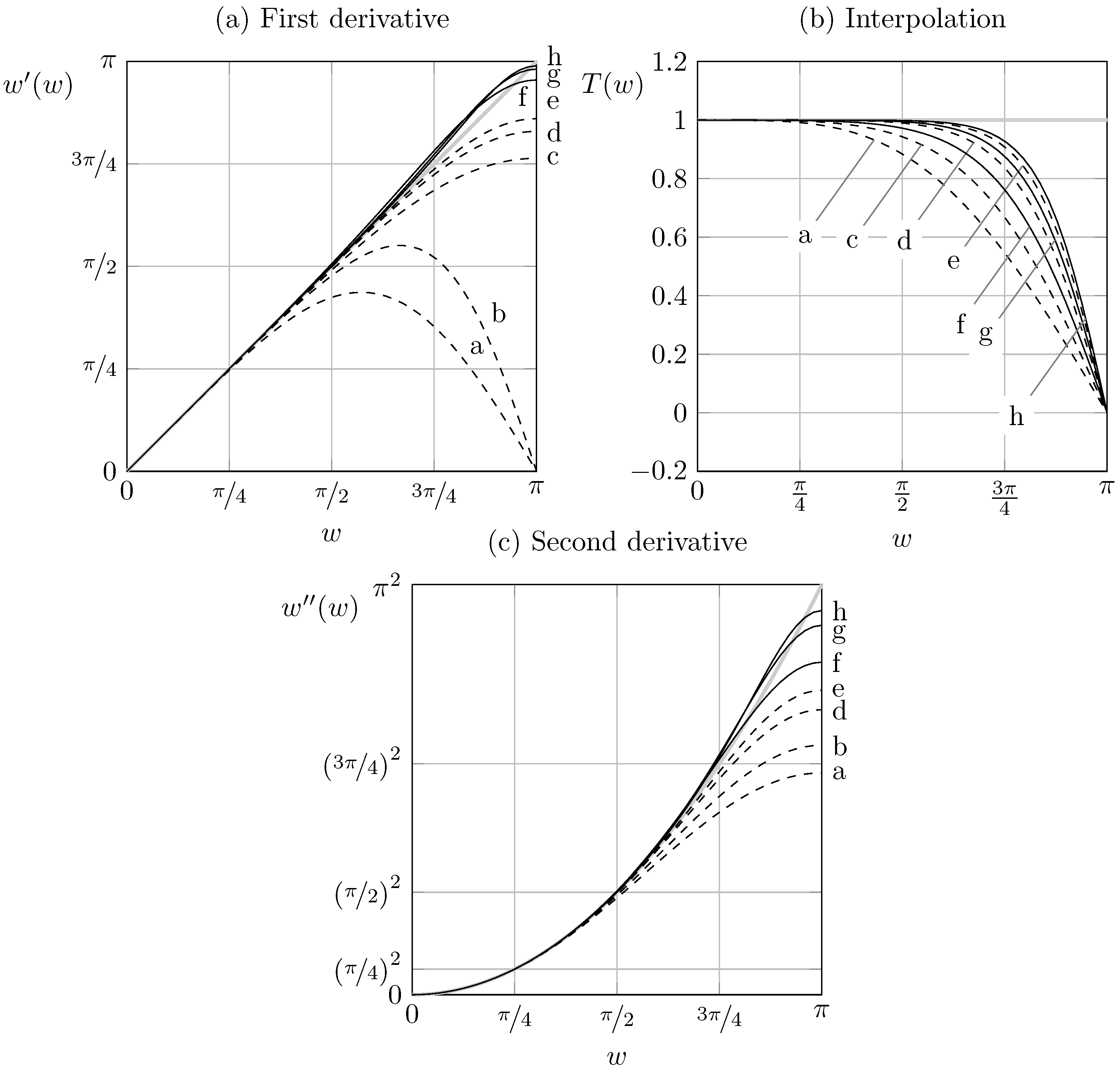
In Figure 4a the scaled modified wavenumber of the proposed schemes for first derivative is compared to the ones relative to classical staggered fourth- and sixth-order tridiagonal compact schemes and to the collocated fourth-order Padé scheme. The modified wavenumber of the explicit fourth-order scheme given by Equation (3) is also shown for comparison. The legend for the curve labels is reported in Table 1. Figure 4a shows that, as compared to classical staggered compact schemes, obtained by maximizing the order of accuracy at fixed stencil, the proposed schemes have improved resolution properties, since the modified wavenumber plots stay close to the exact differentiation curve for a wider range of wavenumbers.
A more quantitative comparison is provided in Table 2 for first derivative schemes, where the classical resolving efficiency e is reported for different values of the error tolerance ε . The efficiency of the scheme is calculated as the shortest normalized wavenumber satisfying the relation
| w w w | ε .
A further indication of the performances of the scheme is represented by the integral resolving efficiency e I , here defined as
e I = 0 π | w w | k   d w ,
that is often used with k = 2 [24,25]. From Table 2 the good performances of the proposed schemes, in comparison with their classical counterparts, is confirmed. The performances of the new schemes are always superior to that of classical staggered schemes when they are measured with the integral resolving efficiency, while are comparable when measured by considering the shortest wavenumber satisfying Equation (33). Similar results, not shown here, were found for interpolation and second derivation formulæ as well.
The modified wavenumber of interpolation and second derivative schemes is presented in Figure 4b,c respectively. Again, the proposed schemes are compared to classical fourth- and sixth- order compact schemes and to fourth-order explicit schemes. The good performances with respect to classical compact schemes of the same order of accuracy is confirmed also in these cases.

3.3. Evaluation of the Computational Effort

The computational cost involved in the classical fourth-order compact schemes, Equations (2), (10) and (12) can be estimated by counting the floating point operations needed for the evaluation of each formula on a mesh of N points. By assuming that both multiplications and sums have the same weight, Equations (2) and (10) require 10 N operations ( 2 N for the evaluation of the right-hand side and 8 N for a standard tridiagonal solver), while Equation (12) requires 14 N operations. In a procedure in which all the three formulæ are needed, as for the case of an incompressible staggered Navier-Stokes solver, the total cost of the fourth-order set of discretizations can be estimated to be 34 N . If one employs the set of compact approximations given by Equations (7), (9) and (11), together with the evaluation of the standard fourth-order Padé scheme Equation (1), the total cost can be estimated to be 27 N operations, 10 N belonging to the standard Padé scheme Equation (1), 5 N for each of the formulæ Equations (7) and (9) and 7 N for Equation (11). The operation-count saving is even more pronounced if one compares the proposed technique with standard formulæ, Equations (30)–(32), or with optimized sixth-order schemes. In both of these last cases the computational effort required for the computation of staggered first derivatives and interpolations and of collocated second derivatives can be estimated to be 42 N operations, 13 N belonging to the schemes Equations (30) and (31) and 16 N belonging to Equation (32).

4. Application to Incompressible Navier-Stokes Equations

The motion of an incompressible fluid is governed by the Navier-Stokes equations,
u i t = u j u i x j P x i + 1 Re 2 u i x j x j + u i ˙ ,
u j x j = 0 ,
where P is the pressure, Re is the Reynolds number, u i are the nondimensional cartesian components of the velocity field, and u i ˙ the components of any given velocity source/sink field. Discretization of Equations (35) and (36) follows here a standard semi-discrete approach [26,27,28], in which the momentum equation is discretized in space and then advanced in time without taking the pressure term into account; subsequently, a Poisson equation is solved for the pressure; finally the divergence-free velocity at the following time level is obtained by correcting with the gradient of pressure.
In Equation (35) the nonlinear convective term is expressed in the so-called advective form. By employing the continuity Equation (36), it can be equivalently expressed in divergence form (i.e., as the divergence of the dyadic tensor u i u j ), or in skew-symmetric form, in which the arithmetic mean of divergence and advective forms is considered. This distinction has little importance on the continuous level, once all the analytical manipulations of standard calculus are assumed to be valid. However, the direct discretization of each form behave usually differently, since the standard rules of calculus (even the simplest ones, as the product rule) are in general not guaranteed to be valid for discrete operators.
The choice of the form in which the convective term is discretized is usually dictated by the behaviour of the discrete set of equations with respect to induced balance equations. The preservation of some global quadratic invariants, such as, for instance, kinetic energy integrated over the whole domain (in the inviscid limit and for periodic or homogeneous flux boundary conditions), is an important target for stable and reliable simulations at high Reynolds numbers [29]. Different strategies have been developed in order to fulfill this requirement, some of which are briefly recalled in the following section. A more in-depth discussion on this and related topics can be found in [30].

4.1. Spatial Discretization

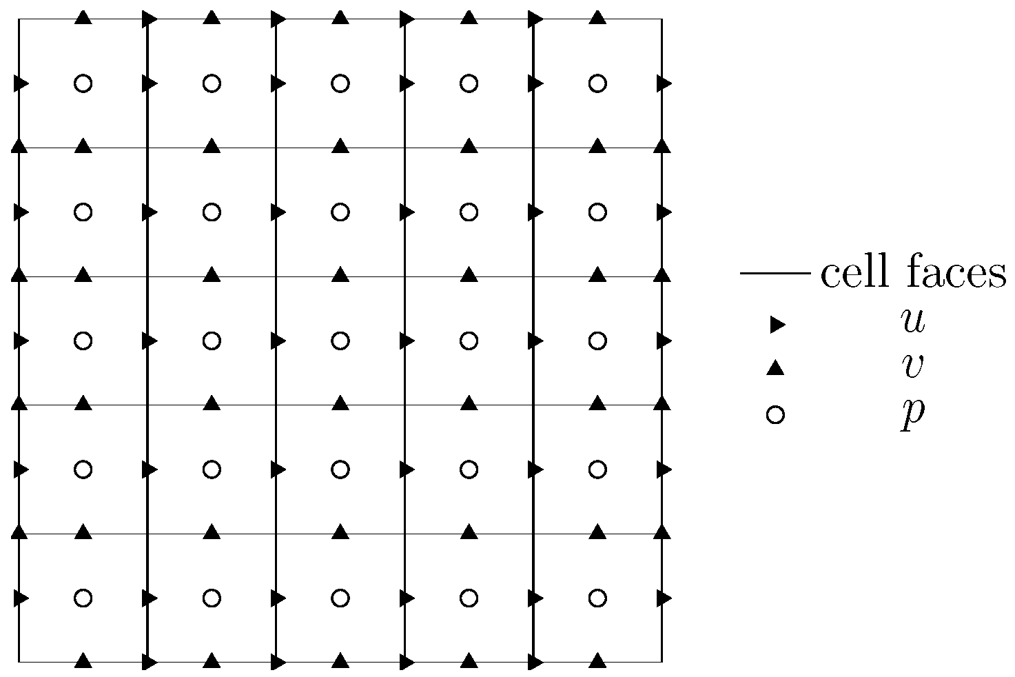
Equations (35) and (36) are firstly discretized on a cartesian spatial mesh, which will be here assumed to be uniform. As it is very common in the numerical discretization of incompressible Navier-Stokes equations, the variables are arranged on a staggered layout, in which velocity components are located on the normal faces of the cells and pressure nodes are positioned at the centers (Figure 5). The staggered arrangement of the variables has been often preferred to the simpler collocated or regular arrangements for incompressible flows, because it provides a more robust link between the discrete variables and avoids the odd-even decoupling of the pressure (also known as pressure checker-boarding problem) [26]. Moreover, it is well known that discrete operators based on explicit and symmetric central differences can easily provide primary (i.e., on mass and momentum) and secondary (e.g., on global kinetic energy) conservation on staggered grids [29]. This is an important topic, since a spatial discretization which is able to enforce conservation of global kinetic energy on a discrete level usually permits to avoid the onset of nonlinear instabilities arising from the accumulation of aliasing errors associated to the discrete evaluation of nonlinear terms [31,32]. The well known second order Harlow-Welch discretization procedure is the simplest example of staggered discretization globally conserving kinetic energy. Moreover, it directly discretizes the divergence form of the convective term, which has several advantages, in terms of local primary conservation properties and reduced computational cost.
The Harlow-Welch procedure has been extended also to higher order central explicit schemes, both on uniform and variable meshes [29,33]. When dealing with implicit (central) compact schemes, however, it is not clear if the discretization of the nonlinear convective term in Equation (35) can be performed directly on the divergence form and still retaining the global conservation of kinetic energy at the discrete level. In this case, the employment of the so-called skew-symmetric splitting is mandatory, as in the case of regular layouts, since it automatically guarantees conservation of global kinetic energy on a semi-discrete level [29]. Recently, other approaches have been proposed, in which the beneficial properties of the skew-symmetric splitting are obtained by properly alternating the more economic divergence and advective forms inside the stages of a multistage time integration procedure [34,35,36]. In this paper, we will not consider these more sophisticated techniques, and will instead rely on the classical skew-symmetric form for the convective term.
One-dimensional derivatives of zeroth, first, and second order are used to discretize spatial operators involved in the computation of the non-linear convective as well as linear viscous terms in Equation (35). While the latter does not require any special attention, the former does, due to its non linearity. On a discrete level, the skew-symmetric form leads a discretization of the i-component of the convective term in momentum equation Equation (35) of the form (cfr. Equations (87) and (89) of Morinishi et al. [29]):
1 2 δ ( u j ¯ x i u i ¯ x j ) δ x j + u j ¯ x i δ u i δ x j ¯ x j ,
where δ / δ x j is the finite difference derivative in direction x j and overbars denote finite difference iterpolations. In our case both differentiations and interpolations are performed by compact formulæ.
Hence, on a fully staggered arrangement of variables, the two addends in (37) are calculated by the following combination of interpolations and differentiantions:
  • Divergence form
    1
    components i and j of velocity are iterpolated in the direction j and i respectively;
    2
    the product is performed;
    3
    the staggered derivative of the product in direction j is computed.
  • Advective form
    1
    components i and j are stagger-differentiated and iterpolated in the directions j and i respectively;
    2
    the product is performed;
    3
    the product is interpolated along direction j.
As regards both point 1 and 2 it is clear that “pure” products are performed at cell centers, whereas mixed products at cell corners (cell edges in 3D). The same holds for the advective form. From Figure 5 one sees that this procedure approximates the convective term on the locations of the variables u i . Please note that the interpolated quantities used to compute the divergence form (step 1) can be reused in the computation of the advective form (step 2).
The divergence and gradient operators required in the pressure correction process (cf. Section 4.2) are built based on one-dimensional derivatives as well. Please note that for consistency, the Laplacian operator comes as a consequence of the discrete product 2 = · . The main and essential difference with respect to the choice made for the convective and viscous terms is that in this paper the one-dimensional derivatives are explicit, instead of compact, with the same order of accuracy. The reason is that compact schemes would have led to a full matrix discretizing the Laplacian operator, which would have been impractical [37]. Please note that this approach, despite the stencil of explicit schemes being wider, only requires one non-symmetric boundary scheme (in the case of 4th order of accuracy) for the application of both divergence and gradient operators.

4.2. Time Integration

Time advancement is accomplished through an explicit Runge-Kutta method. Althoug after spatial discretization the Navier-Stokes equations reduce to a system of ordinary Differential Algebraic Equations, the introduction of a projection operator for the velocity field onto the divergence free subspace, formally conducts to a system of Ordinary Differential Equations, to which standard time integrators can be applied. In this context, the projection step has to be executed at each stage of the RK [38]. By employing a standard notation, the time integration procedure with reference to a generic s-stage explicit Runge-Kutta method can be expressed as:
u i * = u n + Δ t j = 1 i 1 a i j R ( u j ) Δ t · p i = · u i * i = 1 , 2 , , s u i = u i * Δ t p i ,
u * = u n + Δ t j = 1 s b i R ( u i ) Δ t · p n + 1 = · u i * u n + 1 = u * Δ t p n + 1 ,
where u and p are the vectors containing the discretized velocity and pressure fields on the three-dimensional grid, R ( u ) is the right hand side of momentum equation, without the pressure term, once discretized in space and ∇ is the discrete nabla operator, assuming the meaning of discrete divergence or gradient operator, depending on the context. This classical approach of projecting each intermediate field in the context of an explicit RK method (cf. Equation (38)) is quite costly with respect to multisteps methods, since each projection requires the solution of an elliptic equation. More convenient strategies which make use of an extrapolation of the pseudo-pressure and perform only the final projection (39) are possible [39,40].

5. Results

In the following sections, two simulations, aimed at evaluating different performances of the new schemes, are presented. The first test case is an analytical solution of the Navier-Stokes equations, targeted at assessing the theoretically predicted order of accuracy of the proposed method on a Navier-Stokes solver. The second one is a double-mixing layer flow, which, although spatially periodic, presents creation of smaller scales from a smooth initial condition, and is hence targeted at evaluating the resolving capabilities of the method.

5.1. Burggraf Flow

The aim of the present section is to reliably assess the formal accuracy of the novel compact method through the simulation of analytically solved benchmarks, whose exact solution allows the rigorous computation of the error. Among the scarse class of such flows, the Burggraf flow, a special case of the more general family of lid driven cavity flows, is used in the non-periodic case [41]. Indeed, it is also known as modified or analytical lid driven cavity [42].
The simulation is performed in a square domain D = { 0 x 1 , x 2 1 } whose lid x 2 = 1 is provided with a distribution of tangential velocity u 1 ( x , 1 ) = f ( x 1 ) = 16 x 1 2 ( x 1 1 ) 2 ; furthermore, the vertical component of the momentum equation is forced by the source term
u ˙ 2 = 8 Re 245 g + 2 g h + g 4 h 64 g 2 2 ( h h h h ) h h ( g g g 2 ) ,
where the two functions g and h have the following expressions
g ( x 1 ) = 0 x 1 f ( x 1 ) 16 d x 1 , h ( x 2 ) = x 2 2 ( x 2 2 1 ) .
The exact solution, which is independent of Re, has the following components,
u 1 ex ( x 1 , x 2 ) = + 8 g h ,
u 2 ex ( x 1 , x 2 ) = 8 g h .
The simulation is performed at Re = 100 in a computational domain of N × N grid cells for several resolutions, namely N = 16 , 32 , 64 , 128 , and the stationary state is reached by means of the classic 4th order Runge-Kutta, starting from the initial condition of fluid at rest. The spatial discretization is achieved by means of the fourt-order Hermitian method to compute interpolants and first and second derivatives of velocity based on the velocity components (steps a1 and b1, and computation of the viscous term), and by employing classical fourth order compact schemes to compute interpolants and derivatives of velocity products (steps a3 and b3). It is worth mentioning that the novel Hermitian approach can be used, in principle, also for steps a3 and b3; this choice, however, would be less efficient, since it would require another application of the classic collocated scheme on the products of velocity to feed the Hermitian formulæ.
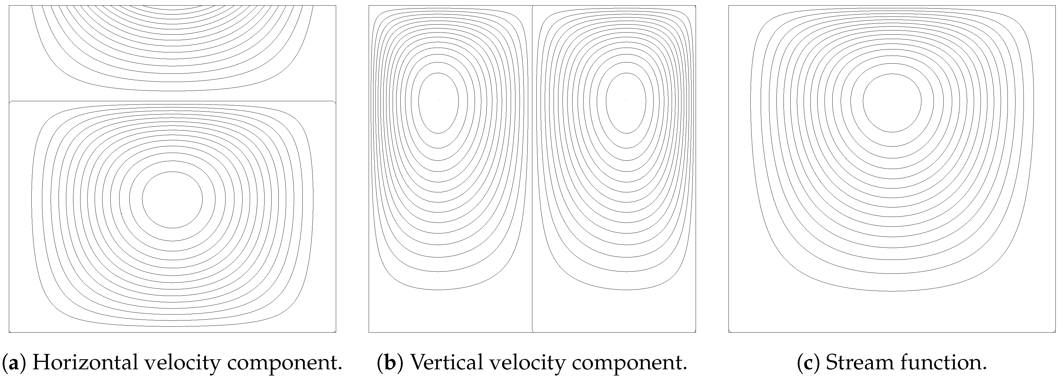
The error of the computed flowfield u with respect to the exact solution u ex , evaluated on the grid, is measured as the infinite norm u u ex , listed in Table 3, and depicted in Figure 6. The contour plots of horizontal and vertical velocity, as well as of the streamfunction are reported in Figure 7.
The theoretical orders of accuracy are generally well reproduced, in some cases showing weak supraconvergence, a behaviour that has been already observed in literature [43].

5.2. Periodic Double Mixing Layer

The second test is a double inviscid mixing layer in a biperiodic domain. This test is challenging for numerical schemes as it presents steep gradients and formation of smaller scales.
The domain is a square region of size 2 π × 2 π with periodic boundary conditions. The mesh has 80 2 cells along each direction, and simulations are time-advanced by means of Runge-Kutta methods.
The Hermitian schemes developed in the paper are tested and compared with classical methods. The code used for this test is based on a standard pseudo-spectral algorithm, and the finite-difference schemes are emulated by means of modified wavenumbers, including shift operators and interpolation transfer functions to cope with the staggered grid. This method is highly efficient for periodic flows and allows great flexibility in comparing several spatial schemes as it only requires plugging the modified wavenumber expression of the derivative and interpolation operators (refer to Appendix A for modified wavenumbers of Hermitian schemes).
The initial flowfield is given by
u = tanh y π / 2 δ , y π , tanh 3 π / 2 y δ , y > π ,
v = ϵ sin ( x ) .
The perturbation on the v-velocity is used to promote the roll-up of the shear layer; as in [35], ϵ = 0.05 is used. A single instability mode is activated by choosing δ = π / 15 .
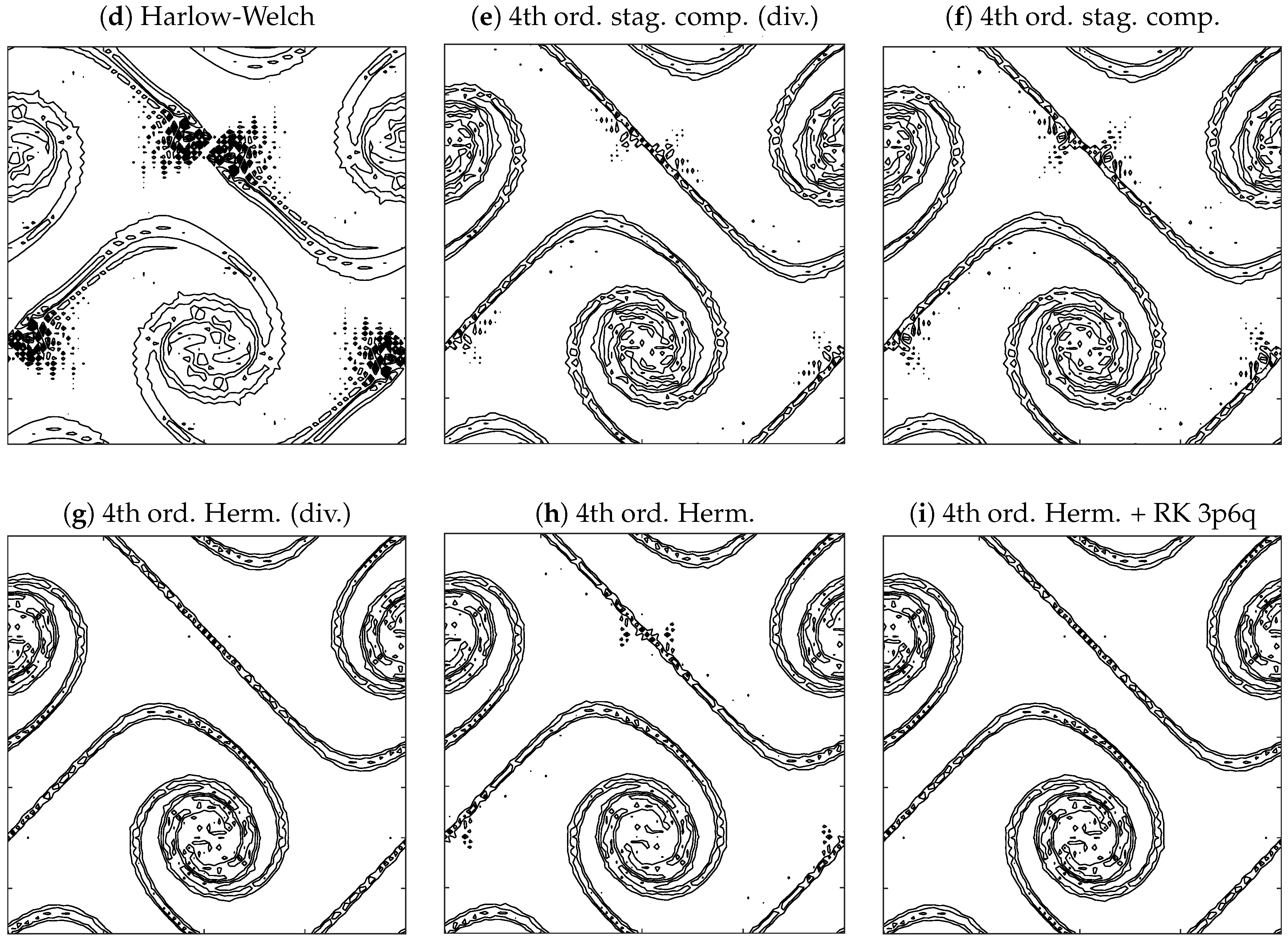
Results are shown in Figure 8 in terms of iso-contours of vorticity at t = 8 , at well-defined shear layer roll-up. In all cases, the skew-symmetric formulation of the convective term and a RK4 scheme for time-advancement are employed, except otherwise indicated. Variables are always arranged on a staggered grid layout. The reference result here is represented by the energy-conserving spectrally-accurate computation. The lower-order explicit schemes provide smeared shear layers and remarkably noisy fields, especially in proximity of the center of the mixing layer, where high gradients are being generated. Although the flowfield improves with the canonical staggered compact method, the novel Hermitian scheme provides the smoothest results, thanks to a favorable combination of high spectral accuracy and discrete energy conservation.
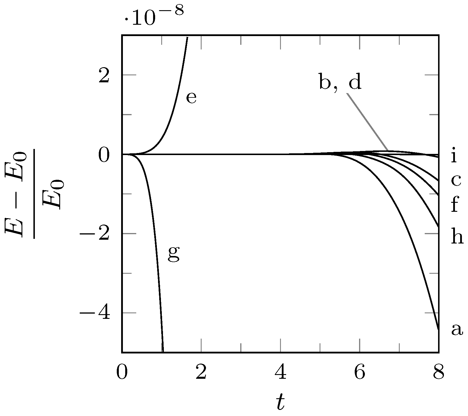
Further insights can be gained by examining the time evolution of kinetic energy, which is shown in Figure 9. Since the case is inviscid, kinetic energy should be ideally preserved in time and stay equal to the initial value. Clearly, any scheme in divergence form does not preserve energy, except the second-order Harlow-Welch method (see left figure). The energy-violating schemes show large oscillations, which could eventually lead to a blow up. On the other hand, all the methods using the skew-symmetric form of convection preserve kinetic energy spatially, and the residual diffusive error is due to the temporal scheme (see right figure, where only methods employing skew-symmetric form are reported). At first, it is interesting to observe that schemes of increasing spatial accuracy are associated to an increasingly more dissipative temporal error. This is due to the fact that smaller scales are being better represented, therefore increasing the enstrophy of the flow (not shown here) and in turn leading to an enhancement in numerical diffusion by the time-advancement scheme. Indeed, the novel Hermitian method performs in between the spectral and the canonical compact staggered schemes. The kinetic energy error can be significantly reduced by coupling the Hermitian scheme with a pseudo-symplectic Runge-Kutta method [44], for instance the 3p6q scheme (third-order accuracte on solution and sixth-order accurate on energy conservation), which requires only one additional stage with respect to the RK4. The resulting velocity field is as accurate as the one provided by the RK4 and contains negligible kinetic energy dissipation.

6. Conclusions

In the context of finite difference approximation of Navier-Stokes equations, staggered grid arrangements are usually employed, because they possess several favourable properties due to a more robust coupling between the discrete sets of variables. Moreover, when dealing with high Reynolds number flows, or in any case in which one is forced to a step size that is at the edge of (or even over) the acceptable resolution, high order and in particular compact schemes are possibly preferred for their improved resolving capabilities. Finally, in these circumstances the discrete approximation of the nonlinear convective term has to be performed by resorting to the so-called skew-symmetric form, in which two different expressions of the convective term are calculated and then averaged. This choice is practically unavoidable if one wants to prevent the nonlinear instability due to the accumulation of aliasing errors.
These considerations show that staggered Navier-Stokes solvers based on compact schemes have several issues. They must compute different interpolations and staggered first derivatives of the velocity field, as well as collocated second derivatives for the approximation of the viscous term. The number of derivatives and interpolations required for each computational node is increased with respect to standard formulations, and each of these approximations needs different closure schemes near the boundaries.
In this paper, a novel procedure to efficiently deal with these difficulties is presented. In this method, a whole set of different compact derivatives and interpolations is computed by explicit formulæ resting on a single preliminarly computed compact approximation. Although a complete optimization of the application of the general theory to an incompressible Navier-Stokes solver has not been attempted, it has been shown that the procedure is cost effective and that conducts to novel compact schemes with interesting resolution properties. Moreover, it simplifies the treatment of boundary conditions, since only one boundary closure is required for the whole set of approximations.
It is interesting to stress that although this paper has focused on the staggered discretization of incompressible flows, the proposed new method can be in principle equally applied to compressible flows. Numerical discretization of compressible flows has been usually carried out by considering regular or collocated arrangements of the variables. Staggered layouts have been considered as unnecessary, because of the absence of spurious modes for the pressure and in light of an increased programming difficulty. However, recently staggered discretizations have been proposed also for compressible flows, with the aim of alleviating the inherent instability of the simulations at high Reynolds numbers [17,45]. In such situations compact schemes and skew-symmetric form of nonlinear convective terms are adopted, and the method here presented applies with slight modifications also to these situations.
As a final comment, it is worth noting that, besides the application here proposed to staggered Navier-Stokes solvers, the theory developed is believed to have a remarkable interest by itself. It estabilishes that sets of compact approximations can be obtained by explicit evaluations based on the computation of a single compact scheme. By resorting to a theory of implicit interpolation, it reveals that a single set of compact derivatives can be associated to a wider family of schemes, whose computation can be efficiently done by explicit formulæ. In some sense, the procedure illustrated can be seen as a prefactorization of a whole family of schemes involving a single basic implict formula and different explicit evaluations.

Author Contributions

Conceptualization, E.M.D.A., G.C., F.C. and L.d.L.; Investigation, E.M.D.A.; Software, F.C.; Supervision, G.C. and L.d.L.; Writing—original draft, E.M.D.A., G.C., F.C. and L.d.L.

Funding

This research received no external funding.

Acknowledgments

Part of this work was supported by a grant of HPC time from CINECA under the ISCRA project TENaCE.

Conflicts of Interest

The authors declare no conflict of interest.

Appendix A. Modified Wavenumber

The first derivative compact schemes from Lele [1] have the following formula:
β f i 2 + α f i 1 + f i + α f i + 1 + β f i + 2 = a f i + 1 f i 1 2 h + b f i + 2 f i 2 4 h + c f i + 3 f i 3 6 h .
Figure A1. Schematic representetion of the stencil corresponding to the two approaches.
Applsci 08 01066 g0a1
From the Fourier analysis the modified wavenumber corresponding to Equation (A1) is found to be
w L ( w ) = a sin ( w ) + b 2 sin ( 2 w ) + c 3 sin ( 3 w ) 1 + 2 α cos ( w ) + 2 β cos ( 2 w ) .
First derivative Hermitian schemes allow the computation of the derivative at staggered points, given the values of the function and the values of its derivative at the meshpoints. They have the following general formula
f i + 1 / 2 = a f i + 1 f i 2 h + b f i + 2 f i 1 4 h + c f i + 3 f i 2 6 h + β f i 1 + α f i + α f i + 1 + β f i + 2 ,
which can be rewritten in symmetric form with the substitution i i 1 2 ,
f i = a f i + 1 / 2 f i 1 / 2 2 h + b f i + 3 / 2 f i 3 / 2 4 h + c f i + 5 / 2 f i 5 / 2 6 h + + β f i 3 / 2 + α f i 1 / 2 + α f i + 1 / 2 + β f i + 3 / 2 .
The wavenumber corresponding to Equation (A3) is easily found to be
w H ( w ) = a h sin w 2 + b 2 h sin 3 w 2 + c 3 h sin 5 w 2 + 2 α cos w 2 + 2 β cos 3 w 2 w ,
where the derivatives at the RHS are supposed to be known exactly. Here we suppose, on the contrary, that only the values of the function (i.e., the values f i ) are assigned and that the compact scheme in Equation (A1) is used to get a larger number of informations which are then used to feed the Hermitian interpolation subtending Equation (A2). In this case, the wavenumber multiplying the square brackets in Equation (A4) is w L , the modified wavenumber pertaining the scheme used to obtain the values f i .
w H ( w ) = a h sin w 2 + b 2 h sin 3 w 2 + c 3 h sin 5 w 2 + 2 α cos w 2 + 2 β cos 3 w 2 w L
Similarly, interpolation Hermitian schemes allow the computation of the interpolant at staggered points, given the values of the function and the values of its derivative at the meshpoints, through the following formula
f i + 1 / 2 = a f i + 1 + f i 2 + b f i + 2 + f i 1 2 + c f i + 3 + f i 2 2 α f i + 1 f i h β f i + 2 + f i 1 3 h ,
which can be again rewritten in symmetric form with the substitution i i 1 2 ,
f i = a f i + 1 / 2 + f i 1 / 2 2 + b f i + 3 / 2 + f i 3 / 2 2 + c f i + 5 / 2 + f i 5 / 2 2 + α f i + 1 / 2 f i 1 / 2 h β f i + 3 / 2 f i 3 / 2 3 h .
The transfer function corresponding to Equation (A7) is easily found to be
T H ( w ) = a cos w 2 + b cos 3 w 2 + c cos 5 w 2 + 2 α h sin w 2 + β 3 h sin 3 w 2 w ,
where the derivatives at the RHS are supposed to be known exactly.
If we suppose, as in the previous case, that the compact scheme in Equation (A1) is used to get a larger number of informations to feed the Hermitian interpolation subtending Equation (A6), the wavenumber multiplying the square brackets in Equation (A8) is w L , the modified wavenumber pertaining the scheme used to obtain the values f i .
T H ( w ) = a cos w 2 + b cos 3 w 2 + c cos 5 w 2 2 α h sin w 2 + β 3 h sin 3 w 2 w L ,
Finally, for the second derivative we have:
f i = a f i + 1 2 f i + f i 1 h 2 + b f i + 2 2 f i + f i 2 4 h 2 + c f i + 3 2 f i + f i 3 9 h 2 + + α f i + 1 f i 1 2 h + β f i + 2 f i 2 4 h .
w H ( w ) = 2 a ( 1 cos ( w ) ) + b 2 ( 1 cos ( 2 w ) ) + 2 c 9 ( 1 cos ( 3 w ) ) + α h sin ( w ) + β 2 h sin ( 2 w ) w L .

References

  1. Lele, S.K. Compact finite difference schemes with spectral-like resolution. J. Comput. Phys. 1992, 103, 16–42. [Google Scholar] [CrossRef]
  2. Collatz, L. The Numerical Treatment of Differential Equations; Springer: New York, NY, USA, 1966; p. 87538. [Google Scholar]
  3. Orszag, S.A.; Israeli, M. Numerical simulation of viscous incompressible flows. Annu. Rev. Fluid Mech. 1974, 6, 281–318. [Google Scholar] [CrossRef]
  4. Strang, G.; Fix, G.J. An Analysis of the Finite Element Method; Prentice-Hall: Englewood Cliffs, NJ, USA, 1973. [Google Scholar]
  5. Ciment, M.; Leventhal, S.H. Higher order compact implicit schemes for the wave equation. Math. Comput. 1975, 29, 985–994. [Google Scholar] [CrossRef]
  6. Adam, Y. A hermitian finite difference method for the solution of parabolic equations. Comput. Math. Appl. 1975, 1, 393–406. [Google Scholar] [CrossRef]
  7. Hirsh, R.S. Higher order accurate difference solutions of fluid mechanics problems by a compact differencing technique. J. Comput. Phys. 1975, 19, 90–109. [Google Scholar] [CrossRef]
  8. Rubin, S.G.; Graves, R.A. Viscous flow solutions with a cubic spline approximation. Comput. Fluids 1975, 3, 1–36. [Google Scholar] [CrossRef]
  9. Rubin, S.; Khosla, P. Higher-order numerical solutions using cubic splines. AIAA J. 1976, 14, 851–858. [Google Scholar] [CrossRef]
  10. Rubin, S.; Khosla, P. Polynomial interpolation methods for viscous flow calculations. J. Comput. Phys. 1977, 24, 217–244. [Google Scholar] [CrossRef]
  11. Ciment, M.; Leventhal, S.H.; Weinberg, B.C. The operator compact implicit method for parabolic equations. J. Comput. Phys. 1978, 28, 135–166. [Google Scholar] [CrossRef] [Green Version]
  12. Adam, Y. Highly accurate compact implicit methods and boundary conditions. J. Comput. Phys. 1977, 24, 10–22. [Google Scholar] [CrossRef]
  13. Chang, H.R.; Shirer, H.N. Compact spatial differencing techniques in numerical modeling. Mon. Weather Rev. 1985, 113, 409–423. [Google Scholar] [CrossRef]
  14. Chu, P.C.; Fan, C. A three-point combined compact difference scheme. J. Comput. Phys. 1998, 140, 370–399. [Google Scholar] [CrossRef]
  15. Chu, P.C.; Fan, C. A three-point sixth-order nonuniform combined compact difference scheme. J. Comput. Phys. 1999, 148, 663–674. [Google Scholar] [CrossRef]
  16. Coppola, G.; Meola, C. Generalization of the spline interpolation based on the principle of the compact schemes. J. Sci. Comput. 2002, 17, 695–706. [Google Scholar] [CrossRef]
  17. Boersma, B.J. A staggered compact finite difference formulation for the compressible Navier-Stokes equations. J. Comput. Phys. 2005, 208, 675–690. [Google Scholar] [CrossRef]
  18. Laizet, S.; Lamballais, E. High-order compact schemes for incompressible flows: A simple and efficient method with quasi-spectral accuracy. J. Comput. Phys. 2009, 228, 5989–6015. [Google Scholar] [CrossRef]
  19. Knikker, R. Study of a staggered fourth-order compact scheme for unsteady incompressible viscous flows. Int. J. Numer. Methods Fluids 2009, 59, 1063–1092. [Google Scholar] [CrossRef]
  20. Kampanis, N.A.; Ekaterinaris, J.A. A staggered grid, high-order accurate method for the incompressible Navier–Stokes equations. J. Comput. Phys. 2006, 215, 589–613. [Google Scholar] [CrossRef]
  21. Tyliszczak, A. A high-order compact difference algorithm for half-staggered grids for laminar and turbulent incompressible flows. J. Comput. Phys. 2014, 276, 438–467. [Google Scholar] [CrossRef]
  22. Quarteroni, A.; Sacco, R.; Saleri, F. Numerical Mathematics; Springer: Berlin, Germany, 2007. [Google Scholar]
  23. Liu, X.; Zhang, S.; Zhang, H.; Shu, C.W. A new class of central compact schemes with spectral-like resolution I: Linear schemes. J. Comput. Phys. 2013, 248, 235–256. [Google Scholar] [CrossRef]
  24. Kim, J.W.; Lee, D.J. Optimized compact finite difference schemes with maximum resolution. AIAA J. 1996, 34, 887–893. [Google Scholar] [CrossRef]
  25. Tam, C.K.; Webb, J.C. Dispersion-relation-preserving finite difference schemes for computational acoustics. J. Comput. Phys. 1993, 107, 262–281. [Google Scholar] [CrossRef]
  26. Ferziger, J.H.; Peric, M. Computational Methods for Fluid Dynamics; Springer: Berlin, Germany, 2012. [Google Scholar]
  27. Perot, J.B. An analysis of the fractional step method. J. Comput. Phys. 1993, 108, 51–58. [Google Scholar] [CrossRef]
  28. Perot, J.B. Comments on the fractional step method. J. Comput. Phys. 1995, 121, 190–191. [Google Scholar] [CrossRef]
  29. Morinishi, Y.; Lund, T.S.; Vasilyev, O.V.; Moin, P. Fully conservative higher order finite difference schemes for incompressible flow. J. Comput. Phys. 1998, 143, 90–124. [Google Scholar] [CrossRef]
  30. Coppola, G.; Capuano, F.; de Luca, L. Energy preserving discretizations of the Navier-Stokes equations. In Classical and modern approaches. In Proceedings of the 23rd Conference of the Italian Association of Theoretical and Applied Mechanics (AIMETA 2017), Salerno, Italy, 4–7 September 2017; Volume 5, pp. 2284–2310. [Google Scholar]
  31. Phillips, N.A. An example of nonlinear computational instability. In The Atmosphere and the Sea in Motion; Rockefeller Institute, Oxford University Press: Oxford, UK, 1959; pp. 501–504. [Google Scholar]
  32. Arakawa, A. Computational design for long-term numerical integration of the equations of fluid motion: Two-dimensional incompressible flow. Part I. J. Comput. Phys. 1966, 1, 119–143. [Google Scholar] [CrossRef]
  33. Verstappen, R.W.C.P.; Veldman, A.E.P. Symmetry–preserving discretization of turbulent flow. J. Comput. Phys. 2003, 187, 343–368. [Google Scholar] [CrossRef]
  34. Capuano, F.; Coppola, G.; de Luca, L. An efficient time advancing strategy for energy-preserving simulations. J. Comput. Phys. 2015, 295, 209–229. [Google Scholar] [CrossRef]
  35. Capuano, F.; Coppola, G.; Balarac, G.; de Luca, L. Energy preserving turbulent simulations at a reduced computational cost. J. Comput. Phys. 2015, 298, 480–494. [Google Scholar] [CrossRef]
  36. Capuano, F.; Coppola, G.; de Luca, L. Low-Cost Energy-Preserving RK Schemes for Turbulent Simulations; Peinke, J., Kampers, G., Oberlack, M., Wacławczyk, M., Talamelli, A., Eds.; Progress in Turbulence VI. Springer Proceedings in Physics; Springer: Cham, Switzerland, 2016; Volume 165, pp. 65–68. [Google Scholar]
  37. Simens, M.P.; Jiménez, J.; Hoyas, S.; Mizuno, Y. A high-resolution code for turbulent boundary layers. J. Comput. Phys. 2009, 228, 4218–4231. [Google Scholar] [CrossRef]
  38. Sanderse, B. Energy-conserving Runge–Kutta methods for the incompressible Navier–Stokes equations. J. Comput. Phys. 2013, 233, 100–131. [Google Scholar] [CrossRef]
  39. Le, H.; Moin, P. An improvement of fractional step methods for the incompressible Navier-Stokes equations. J. Comput. Phys. 1991, 92, 369–379. [Google Scholar] [CrossRef]
  40. Capuano, F.; Coppola, G.; Chiatto, M.; de Luca, L. Approximate projection method for the incompressible Navier–Stokes equations. AIAA J. 2016, 54, 2179–2182. [Google Scholar] [CrossRef]
  41. Laizet, S.; Li, N. Incompact3d: A powerful tool to tackle turbulence problems with up to O (105) computational cores. Int. J. Numer. Methods Fluids 2011, 67, 1735–1757. [Google Scholar] [CrossRef]
  42. Pereira, J.; Kobayashi, M.; Pereira, J. A fourth-order-accurate finite volume compact method for the incompressible Navier–Stokes solutions. J. Comput. Phys. 2001, 167, 217–243. [Google Scholar] [CrossRef]
  43. Lacor, C.; Smirnov, S.; Baelmans, M. A finite volume formulation of compact central schemes on arbitrary structured grids. J. Comput. Phys. 2004, 198, 535–566. [Google Scholar] [CrossRef]
  44. Capuano, F.; Coppola, G.; Rández, L.; de Luca, L. Explicit Runge-Kutta schemes for incompressible flow with improved energy-conservation properties. J. Comput. Phys. 2017, 328, 86–94. [Google Scholar] [CrossRef]
  45. Nagarajan, S.; Lele, S.K.; Ferziger, J.H. A robust high-order compact method for large eddy simulation. J. Comput. Phys. 2003, 191, 392–419. [Google Scholar] [CrossRef]
Figure 1. Graphical representation of explicit and compact schemes. (a) Classical second order explicit formula for second derivative. (b) Staggered explicit scheme of Equation (3). (c) Padé fourth order scheme, Equation (1). (d) Fourth order staggered compact derivative, Equation (2).
Applsci 08 01066 g001
Figure 2. Graphical representation of new schemes. (a) Staggered fourth order Hermitian derivative scheme (Equation (7)). (b) Staggered fourth order interpolation scheme (Equation (9)). (c) Collocated fourth order second derivative scheme (Equation (11)).
Applsci 08 01066 g002
Figure 3. Graphical representation of new schemes. (a) Staggered sixth order Hermitian derivative scheme (Equation (15)). (b) Staggered sixth order interpolation scheme (Equation (8)). (c) Collocated sixth order second derivative scheme (Equation (22)).
Applsci 08 01066 g003
Figure 4. Modified wavenumbers/transfer functions relative to several compact and Hermitian schemes, for interpolation, first derivative, and second derivative formulæ. Refer to Table 1 for schemes legend. Solid and dashed lines are relative to novel and classical schemes respectively.
Applsci 08 01066 g004
Figure 5. Fully staggered layout of variables.
Applsci 08 01066 g005
Figure 6. Error on u 1 and u 2 as function of the number of meshpoints per direction. The values are reported in Table 3 and are relative to the Burggraf flow testcase.
Applsci 08 01066 g006
Figure 7. Contour plots of horizontal and vertical velocity component as well as stream function for the Burggraf flow testcase.
Applsci 08 01066 g007
Figure 8. Iso-contours of vorticity for levels 6 , 4 , , + 6 at time t = 8 for several schemes and formulations. In all cases, the skew-symmetric form of the convective term is employed and the classical RK4 scheme is used for time integration, unless otherwise specified. The first row shows results for explicit schemes of increasing accuracy on a collocated layout; the second row refers to classical compact schemes on a staggered layout; the third row to the novel Hermitian schemes on a staggered layout.
Applsci 08 01066 g008aApplsci 08 01066 g008b
Figure 9. Time evolution of kinetic energy for all the methods presented in Figure 8, which also serves as a reference for the labels.
Applsci 08 01066 g009
Table 1. Legends corresponding to Figure 4, with letters a–e referring to classical schemes (dashed lines in Figure 4), whereas f–g to novel schemes (solid lines in the same figure). On the side of each label representing a scheme, the corresponding equation is referenced.
Curve LabelFigure 4aFigure 4bFigure 4c
a4CE-D14SE-D04CE-D2
b4CC-D1 (1) 4CC-D2 (12)
c4SC-D1 (2)4SC-D0 (10)
d6SC-D1 (17)6SC-D0 (20)5CC-D2 (24)
e8SC-D1 (18)8SC-D0 (21)7CC-D2 (25)
f4SH-D1 (7)4SH-D0 (9)4CH-D2 (11)
g6SH-D1 (15)6SH-D0 (8)6CH-D2 (22)
h8SH-D1 (16)8SH-D0 (19)8CH-D2 (23)
Table 2. Resolving efficiency e and integral resolving efficiency e I for selected classical and new first derivation schemes.
Schemee—Equation (33) e I —Equation (34)
ε = 0.1 ε = 0.01 ε = 0.001 k = 1 k = 2
4CE-D10.4440.2400.1330.5400.135
4CC-D1 (Equation (1))0.5940.3550.2050.6680.402
4SC-D1 (Equation (2))0.7820.4320.2430.9150.965
6SC-D1 (Equation (17))0.9020.6120.4210.9540.986
8SC-D1 (Equation (18))0.9500.7020.5300.9690.993
4SH-D1 (Equations (1) and (7))1.0000.4680.2600.9770.998
6SH-D1 (Equations (13) and (15))1.0000.6010.4050.9810.998
8SH-D1 (Equations(14) and (16))1.0000.6780.4990.9850.999
Table 3. Grid refinement study for Burggraf flow for u 1 and u 2 . The values are depicted in Figure 6.
u 1 u 2
NErrorOrderErrorOrder
164.167 × 10−44.683 × 10−4
321.812 × 10−54.5232.730 × 10−54.100
646.333 × 10−74.8381.066 × 10−64.677
1282.564 × 10−84.6263.752 × 10−84.829