Review

Noise Suppression Strategies in Computer Holography: Methods and Techniques

by
Songzhi Tian
1,
Zijia Feng
1,2,
Hao Zhang
1,*,
Qiaofeng Tan
1 and
Liqun Sun
1
1
State Key Laboratory of Precision Measurement Technology and Instruments, Department of Precision Instrument, Tsinghua University, Beijing 100084, China
2
Weiyang College, Tsinghua University, Beijing 100084, China
*
Author to whom correspondence should be addressed.
Submission received: 30 June 2025 / Revised: 7 August 2025 / Accepted: 8 September 2025 / Published: 11 September 2025

Abstract

Computer holography enables precise modulation of optical fields, facilitating advanced applications such as optical manipulation, micro-/nanofabrication, and high-resolution three-dimensional displays. However, noise remains one of the most critical challenges, as it significantly reduces the accuracy and visual quality of the reconstructed optical fields. Over the past decades, substantial research has been devoted to identifying noise sources and developing a wide range of suppression techniques. In this article, we present a systematic analysis of the origins and characteristics of noise in computer holography, structured based on computational methods, device characteristics, and system configurations. The representative suppression strategies aimed at enhancing holographic reconstruction quality are investigated. This study aims to deepen the understanding of noise characteristics and provide valuable insights and guidance for future developments in hologram optimization, system integration, and high-performance holographic reconstruction techniques.

1. Introduction

The concept of holography was first introduced by Dennis Gabor in 1948, laying the theoretical foundation for wavefront reconstruction based on interference and diffraction principles [1]. In the early stages, holography was implemented optically [2,3,4]. The wavefront information of an object was recorded by interfering it with reference beams on a photosensitive material to form a hologram. The recorded hologram is then illuminated by the reference beam to reconstruct the original wavefront through diffraction. With the development of digital technologies, two major branches of holography emerged. One is digital holography, where the interference pattern is recorded using an image sensor and numerically reconstructed to retrieve the object wavefront [5,6,7]. The other is computer holography, in which holograms are numerically synthesized from known or designed wavefronts and then optically reconstructed to reproduce the desired light field [8,9,10,11]. This review focuses exclusively on computer holography, a technique that not only enables the reconstruction of virtual object wavefronts but also offers great flexibility in hologram design, making it widely applicable. Advancements in computational power and optical modulation technologies have further enabled the widespread application of computer-generated holography (CGH) across various fields. Holographic display enables true three-dimensional (3D) image reconstruction with continuous depth cues, making it a promising technology for next-generation visual systems such as virtual reality (VR), augmented reality (AR), and head-up displays (HUDs) [12,13,14,15,16,17]. In holographic optical tweezers, CGH enables dynamic and precise control of multiple optical traps for manipulating microscopic particles or biological specimens [18,19,20]. For laser micro-/nanofabrication, computer holography enables parallel processing and the generation of complex patterns, thereby enhancing both resolution and efficiency [21]. In addition, CGH finds broad applications in a range of other areas, including holographic lithography [22], optical computing [23], optical communication [24], beam shaping [25,26,27,28], and optical data storage [29]. These diverse applications highlight the versatility and transformative potential of CGH in modern optics and photonics.
Despite broad applicability and versatility of CGH, a persistent challenge in CGH is the presence of noise in the reconstructed optical fields. In practical implementations, noise may arise throughout the entire CGH pipeline, spanning from numerical computation of holograms to optical wavefront reconstruction, as illustrated in Figure 1. These noise components often degrade image fidelity, reduce contrast, and introduce unwanted patterns, ultimately compromising reconstruction quality and limiting broader applications. Therefore, achieving high-quality holographic reconstruction requires comprehensive noise suppression strategies that consider both numerical and physical sources of degradation. This review presents a systematic analysis of noise in CGH, with a particular emphasis on understanding its origins, characteristics, and suppression strategies.
Specifically, we analyze the noise sources from multiple perspectives, including the hologram generation process, the characteristics of key devices in holographic systems, and the configuration of the overall optical setup. In the hologram generation process, a diffraction model is first established to calculate the complex amplitude wavefront on the hologram plane, which is then converted into a physically realizable hologram using encoding or optimization algorithms. Inaccuracies in the diffraction model can lead to significant discrepancies between simulated and experimental results, which are often difficult to compensate for in later optimization stages. A more detailed discussion of diffraction models is presented in Section 2. Moreover, solving for holograms using encoding or optimization algorithms represents an ill-posed problem, and the choice of algorithm strongly influences the noise characteristics and reconstruction quality, as discussed in Section 3. The core components of a CGH system include the modulation device and the light source, both of which significantly influence the noise in the reconstructed fields. The hologram is physically implemented using a modulation device, but practical limitations often lead to discrepancies between the ideal hologram and the actual modulation, leading to various forms of noise, such as high diffraction order noise, quantization noise, and zero-order noise. These issues are covered in Section 4. Additionally, the use of coherent light sources in holographic systems introduces coherent noise, including speckles and interference artifacts. In Section 5, we examine the formation mechanisms and spectral characteristics of coherent noise and review relevant suppression methods. Finally, optical system imperfections introduce additional types of noise, such as misalignment, lens aberrations, distortions, as well as scattering caused by surface roughness and dust particles. These noise sources are often complex, hard to model, and difficult to eliminate entirely. Section 6 offers a discussion of their implications. Notably, the noise contributions from different stages are not independent, and the cumulative effect of each component influences overall system performance. Therefore, achieving a well-balanced trade-off between various factors is crucial for optimal holographic system design.
This review aims to provide a comprehensive and structured perspective on noise in CGH systems. By tracing noise mechanisms across the entire CGH pipeline, we seek to guide researchers toward a deeper understanding of when and how noise arises, and how it can be effectively mitigated. In doing so, we hope to offer practical insights that support the development of advanced algorithms, improved optical systems, and high-quality holographic reconstruction techniques.

2. Diffraction Calculations

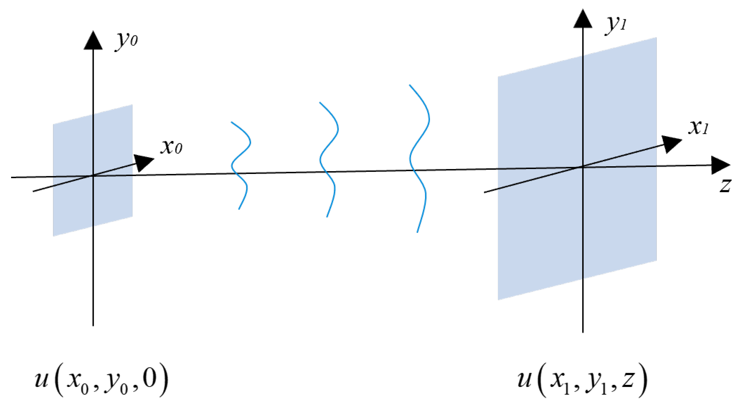
Diffraction calculation is a well-established area in physical optics, with numerous theoretical models guiding its implementation and accurate numerical computation [30,31,32,33]. The primary computational task is to obtain the complex amplitude u ( x 1 , y 1 , z ) at the destination plane located a distance z from the source plane, given the complex amplitude u ( x 0 , y 0 , 0 ) , as illustrated in Figure 2. Here, ( x 0 , y 0 ) and ( x 1 , y 1 ) denote coordinates on the source and destination planes, respectively. Popular algorithms include the single FFT-based Fresnel transform, the Fresnel transfer function (Fres-TF) method, the Fresnel impulse response (Fres-IR) method, the angular spectrum method (ASM), and the Rayleigh–Sommerfeld convolution (RSC). Among them, the Fres-TF method represents diffraction as a multiplication in the frequency domain via a transfer function, while the Fres-IR method interprets it as a spatial-domain convolution using an impulse response kernel. Both are based on the paraxial approximation and are suitable for relatively small diffraction angles. In contrast, the ASM and RSC are non-paraxial methods, providing more rigorous diffraction models in the frequency and spatial domains, respectively. Based on above free-space propagation models, holograms designed using the Fresnel diffraction approximation are commonly called Fresnel holograms. The above free-space propagation models form the basis for Fresnel holography, in which holograms are reconstructed at finite distances with flexible depth control. Alternatively, Fourier holography utilizes a lens to perform an optical Fourier transform, where the hologram is placed at the front focal plane and the reconstruction appears at the back focal plane. This corresponds to the far-field diffraction regime and simplifies numerical calculations. However, Fourier holography generally has limited depth reconstruction capability and is not well suited for three-dimensional light field generation. Both methods have distinct advantages and limitations, and the choice between them depends on the specific requirements of the holographic application. While all diffraction models ultimately require discretization for numerical implementation, the specific sampling conditions vary depending on the chosen method and propagation parameters [34,35,36]. Sampling plays a crucial role in discrete diffraction calculations. According to the sampling theorem, the sampling frequency must be at least twice the maximum signal frequency to avoid aliasing. Insufficient sampling may lead to aliasing and reduce the fidelity of the reconstructed wavefield. Fields containing higher spatial frequency components are particularly vulnerable to aliasing effects. Extensive studies have focused on the sampling and numerical computation of complex amplitude fields [37,38,39]. However, phase, intensity, and amplitude are derived from the complex amplitude through nonlinear operations and therefore require distinct sampling strategies. In the following, we analyze the sampling requirements for phase, intensity, and amplitude individually.

2.1. Sampling of Phase

In diffraction calculations, the phase term appears in both the transfer function and the point spread function. This phase term is typically a chirp function expressed as:
g ( x , y ) = exp j φ ( x , y ) = exp j π β ( x 2 + y 2 ) ,
where ( x , y ) denotes the spatial coordinate, and β is the chirp rate that varies with the specific diffraction algorithm. The local bandwidth in the x-direction is:
B x ( x , y ) = 1 2 π x π β ( x 2 + y 2 ) = β x .
The y-direction expression is analogous. Clearly, the local spatial frequencies depend on both the chirp rate β and the position location ( x , y ) . Generally speaking, the chirp function has finite spatial extent and a maximum spatial frequency. Therefore, according to the sampling theorem, to avoid aliasing, the following condition must be satisfied:
β x max 1 2 Δ x , β y max 1 2 Δ y ,
where Δ x and Δ y represent the sampling intervals in the x and y directions, respectively. Based on this, we can determine the sampling condition that must be satisfied to avoid aliasing [36,40,41]. Taking the one-dimensional Fres-IR method as an example, the output field u ( x 1 , z ) is the convolution of the input field u ( x 0 , 0 ) with the impulse response function h ( X ) . The explicit expression of h ( X ) is given by
h ( x ) = exp j 2 π z / λ j λ z exp j π λ z x 2 ,
where λ is the wavelength. The first term exp j 2 π z / λ / j λ z is a constant factor and does not cause aliasing. The second term exp j π x 2 / λ z is a chirp function. To satisfy the sampling theorem, it is required that:
x λ z max = L x 2 λ z = N Δ x 2 λ z 1 2 Δ x ,
where L x = N Δ x is the spatial size of the diffraction field and N is the number of sampling points. Based on this, we have:
z N Δ x 2 λ = z c ,
Thus, aliasing is avoided when z z c , while aliasing occurs when z < z c .
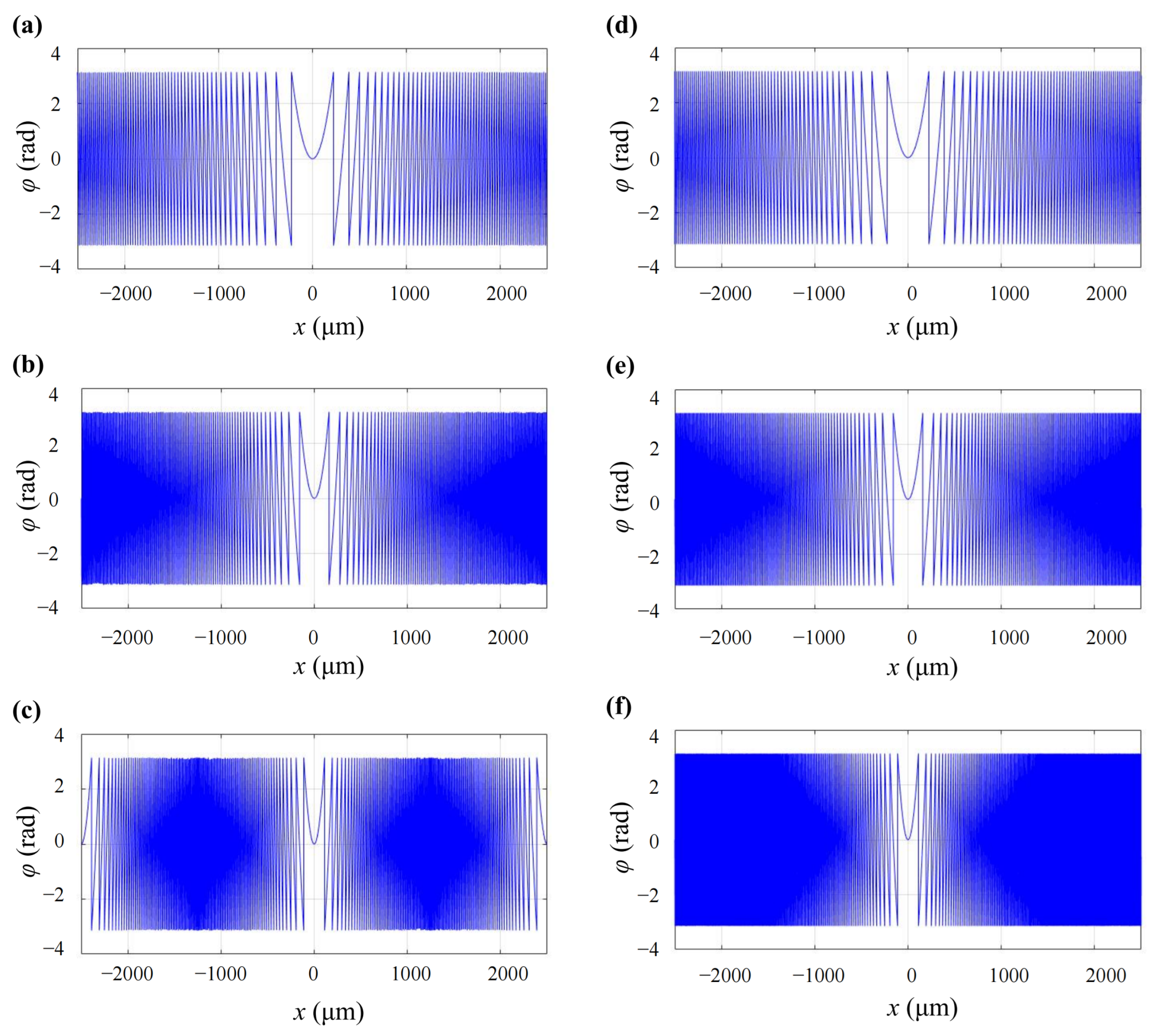
To verify the above analysis, we compare the discrete sampling of the function φ ( x ) = π x 2 / λ z under different values of z, as shown in Figure 3. All sampled signals are reconstructed using sinc interpolation to approximate the continuous phase profiles. In the left column of Figure 3, corresponding to Figure 3a–c, the sampling parameters are N = 1000 and Δ x = 5 μ m , resulting in a critical distance of z c = 5 cm . The right column serves as a reference group, with sampling parameters N = 10 , 000 and Δ x = 0.5 μ m , ensuring correct sampling. From top to bottom of Figure 3, the three rows correspond to discrete sampling results under different propagation distances: z = 10 cm > z c , z = 5 cm = z c , and z = 2.5 cm < z c , respectively. It can be observed that when z z c , the sampling error is negligible. In contrast, when z < z c , severe aliasing occurs, as the sampling condition is not satisfied.
With similar analysis, we may conclude that the RSC algorithm is also suitable for long-distance diffraction but suffers aliasing at short ranges. In contrast, the Fre-TF and ASM methods are prone to aliasing at longer propagation distances. The specific sampling phases, sampling conditions, and non-aliasing regions for each diffraction algorithm are summarized in Table 1. Aliasing noise can be eliminated by oversampling [42,43]; however, as the maximum spatial frequency increases, the required computational cost grows rapidly. One approach is to set the aliased components to zero, known as the band-limiting method [44,45]. However, as the maximum spatial frequency increases, the number of effective sampling points decreases accordingly. Non-uniform sampling can increase the number of effective sampling points, but it does not extend the spatial frequency [46]. The band-extended ASM extends the effective bandwidth by rearranging the sampling points in the spatial frequency domain, thereby improving computational accuracy [47].

2.2. Sampling of Intensity

In many cases, only the intensity I of the reconstructed optical fields is of interest, which can be obtained as
I ( x , y ) = | u ( x , y ) | 2 = u ( x , y ) · u ( x , y ) ,
where u ( x , y ) is the complex amplitude of the optical field and u ( x , y ) denotes its complex conjugate. According to the autocorrelation theorem, the following relation holds [35]:
F { I ( x , y ) } = F { u ( x , y ) } F { u ( x , y ) } ,
where F { · } denotes the two-dimensional Fourier transform operator, and ⋆ represents the autocorrelation operation. This implies that the bandwidth of the intensity B I can reach up to twice the local spatial bandwidth of the complex amplitude B L [48]:
B I 2 B L .
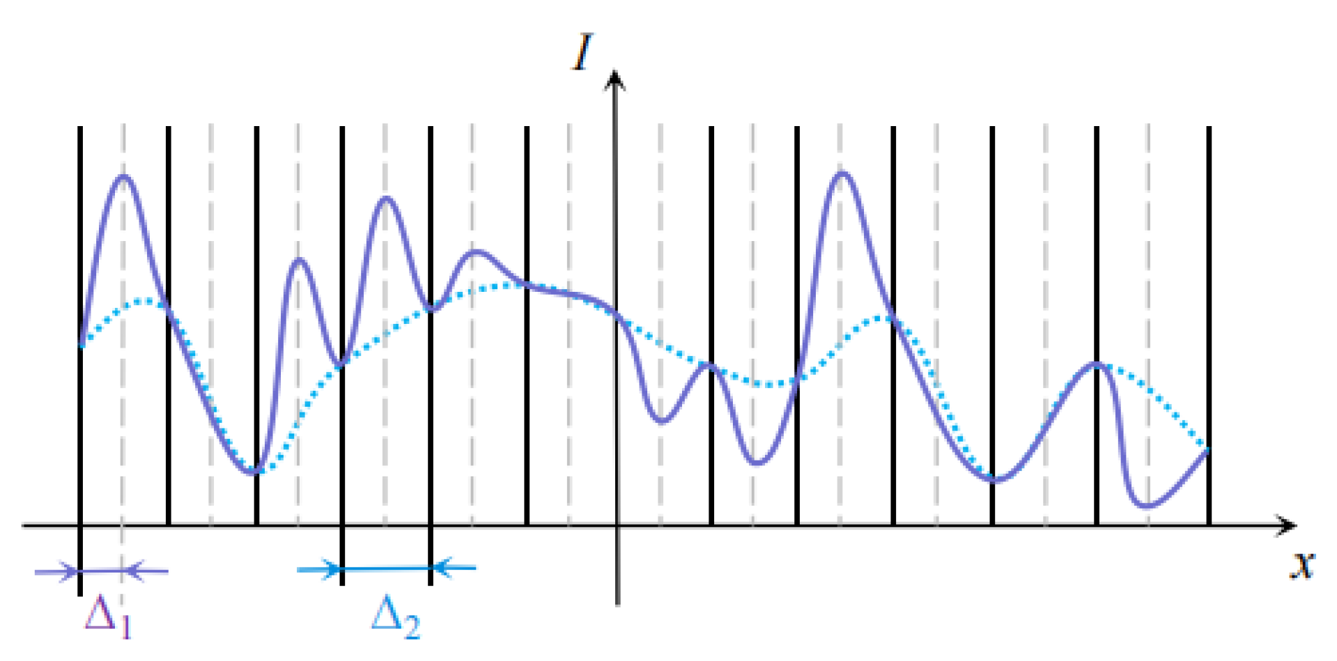
Therefore, to accurately represent the intensity distribution, the sampling interval should typically be half of that used for the complex amplitude [49]. However, many works only ensure proper sampling of the complex amplitude, as illustrated in Figure 4. When the sampling interval is Δ 2 , the numerically reconstructed intensity in these works closely aligns with the target intensity at the sampled points (shown as the blue dashed line). Nevertheless, due to insufficient sampling, the intermediate points are not constrained and may deviate significantly from the target intensity distribution, as indicated by the solid purple line. As a result, the optical reconstruction does not achieve the expected performance indicated by the simulation results.
Wyrowski et al. addressed this issue by zero-padding the hologram plane to increase the sampling density on the reconstruction plane [49,50,51,52]. Subsequently, several derived methods have been proposed to address this problem in various application scenarios [53,54,55].

2.3. Sampling of Amplitude

In amplitude holography, the amplitude of the wavefront needs to be sampled discretely, and its bandwidth must be considered to ensure accurate reconstruction [56]. Note that the amplitude field does not necessarily have a strict bandwidth, even when the complex amplitude and intensity are strictly band-limited. Therefore, the root mean square (RMS) bandwidth is commonly used to estimate the effective bandwidth of the amplitude field, as it characterizes the spatial spectrum range containing most of the energy [57]. The bandwidth characteristics of the amplitude field under Fresnel diffraction were analyzed, and it was shown that the RMS bandwidth satisfies the following constraint [48]:
B A min L 0 λ z , B u ,
where L 0 is the spatial extent of the field at the source plane, and B u is the bandwidth of the complex amplitude. The RMS bandwidth B A depends on the diffraction distance z. When z L 0 / ( λ B u ) , B A = B u . When z > L 0 / ( λ B u ) , B A = L 0 / ( λ z ) . Notably, setting the sampling frequency based on the RMS bandwidth B A ensures only acceptable results, and may not always provide sufficient accuracy.

3. Encoding and Optimization Algorithms

Through the diffraction calculation described above, the complex amplitude wavefront of the target field at the hologram plane can be obtained. However, most devices cannot directly modulate complex amplitudes and are typically restricted to amplitude-only or phase-only modulation. As a result, the complex wavefront must be encoded into a compatible hologram format, which inevitably introduces noise. To enhance the reconstructed reconstruction quality, various optimization algorithms have been proposed. Nevertheless, noise is difficult to eliminate completely, as the hologram calculation is an ill-posed problem yielding only approximate solutions. The design of encoding and optimization algorithms significantly affects both the type of noise and the quality of the reconstructed wavefront.

3.1. Encoding Method

Early CGHs were binary amplitude holograms, constrained by fabrication techniques of the time. A representative encoding technique is the detour phase method proposed by Lohmann [8,9]. As amplitude holograms are constrained to real-valued fields, the reconstructed fields typically suffer from the zero-order noise and conjugate image terms. Improved encoding techniques, such as the Burch modified off-axis method [58], the Lee–WaiHon method [59,60], and the single-sideband method [61], enhance reconstruction quality by separating the reconstructed fields from these undesired terms. Since then, considerable efforts have been devoted to improving the reconstruction quality of amplitude holograms [62,63,64,65].
With higher diffraction efficiency and no conjugate image, phase holograms are widely utilized in computer holography systems [12,66]. Common encoding methods include error diffusion and double-phase encoding techniques. The error diffusion method diffuses quantization errors to neighboring pixels in the phase hologram, as shown in Figure 5a, thereby effectively suppressing quantization artifacts [67,68,69]. Moreover, since the weight coefficients are empirically set, the encoding process may introduce coding noise and background noise in the reconstructed field [70]. Many studies have improved the reconstruction quality by modifying the error diffusion formula, and have demonstrated high-quality reconstructed fields as a result [71,72,73,74]. However, while spreading quantization errors to high-frequency regions helps improve reconstruction quality, it also causes energy to spread into higher diffraction orders, leading to low diffraction efficiency. The double-phase method decomposes the complex amplitude wavefront into two phase components, which are then combined using a complementary checkerboard pattern to form a phase-only hologram [75]. However, due to spatial shifting during the recombination process, encoding noise terms inevitably arise. Several studies have been devoted to suppressing encoding noise [76,77,78]. The spectral distribution of the double-phase hologram was analyzed [79], as shown in Figure 5b. Due to the pixelated structure of the SLM, both the signal and noise components are modulated by distinct envelope functions in the frequency domain. Based on this, the band-limited double-phase method has been proposed, which employs a specially designed spatial filter to more effectively suppress the influence of encoding noise. By applying appropriate filtering and incorporating optimization algorithms, the encoding noise can be effectively suppressed, enabling high-quality reconstruction of the target optical field. However, a significant portion of the optical energy is diverted into encoding noise components, resulting in low diffraction efficiency, which typically does not exceed 30 % [76,80].

3.2. Optimization Algorithms

When only the intensity of the reconstructed field is of interest, the phase can be considered as a free parameter, and the phase hologram computation becomes an optimization problem. Optimization algorithms for phase holograms include search algorithms, alternating projection methods, the gradient-based methods and deep learning approaches. Search algorithms aim to find globally optimal solutions by exploring the entire solution space. Examples include simulated annealing [81], genetic algorithms [82], particle swarm optimization [83], and the direct binary search algorithm [84]. However, these algorithms often involve long computation times, making them unsuitable for real-time light field control.
Alternating projection algorithms solve for the phase by iteratively projecting the solution between constraint sets defined on the hologram and reconstruction planes, as shown in Figure 6a. These constraints are executed differently in different algorithms. The optical fields on the two planes are computed via inverse diffraction P 1 ( · ) and forward diffraction P ( · ) , respectively. The Gerchberg–Saxton (GS) algorithm was the earliest and most representative in this category [85]. Fourier transforms are applied between the two planes, and amplitude constraints are enforced on each plane. However, GS can become trapped in local minima, degrading reconstruction quality. To address this issue, Fienup proposed the input–output algorithm, which incorporates negative feedback to accelerate convergence and improve results [86,87,88]. Moreover, the introduction of an unconstrained region enhances degrees of freedom of the algorithm, thereby improving reconstruction quality [89]. The weighted GS algorithm (GSW) applies constraints by multiplying the target object amplitude with weight coefficients, aiming to accelerate convergence and suppress noise [90,91,92]. In addition, numerous optimization algorithms based on the alternating projection framework have been proposed to achieve high-quality reconstructions under various scenarios [90,93,94].
Hologram optimization can be formulated as an unconstrained minimization problem aimed at reducing the discrepancy between the reconstructed and target optical fields. Gradient-based methods are widely used to solve such problems, as illustrated in Figure 6b. The reconstructed field is obtained through forward diffraction propagation, followed by the construction of a loss function that quantifies its difference from the target. The gradient of the loss with respect to the hologram phase is then computed, and the phase is updated via gradient descent. Depending on the type of gradient used, gradient-based methods can be broadly categorized into first-order and second-order methods. A representative first-order method is stochastic gradient descent (SGD), which was initially applied to phase retrieval problems [95,96], and has more recently been adapted for computer-generated holography (CGH). An SGD-based method for optimizing complex-amplitude holograms was proposed, in which the gradient was computed using Wirtinger derivatives [97]. Camera-captured images were incorporated into the SGD framework to suppress system noise [98]. Subsequently, several SGD-based holography algorithms have been developed by improving forward propagation models and designing more effective loss functions [99,100,101]. In contrast, second-order gradient methods compute not only the gradient but also the second-order derivatives, thereby identifying directions of faster convergence in the loss landscape. A representative example is the quasi-Newton method. Quasi-Newton optimization was applied to compute holograms for 3D light field reconstruction [102], and was also used for the generation of complex-amplitude holograms [97]. Although quasi-Newton methods offer greater potential for finding globally optimal solutions, they are often computationally expensive. In summary, alternating projection algorithms are easy to implement and converge quickly in simple settings, making them suitable for low-resolution or real-time applications. However, their optimization flexibility is limited, and they are prone to getting trapped in local minima, which can degrade reconstruction quality. Gradient-based methods, in contrast, can escape local minima and produce higher-fidelity reconstructions by directly minimizing a loss function. They are especially effective when combined with data-driven priors or camera feedback. Although they typically require higher computational cost, their efficiency can be significantly improved by leveraging parallel computing on GPUs. Therefore, the choice between the two methods depends on the specific application requirements and the trade-off between image quality, speed, and implementation complexity.
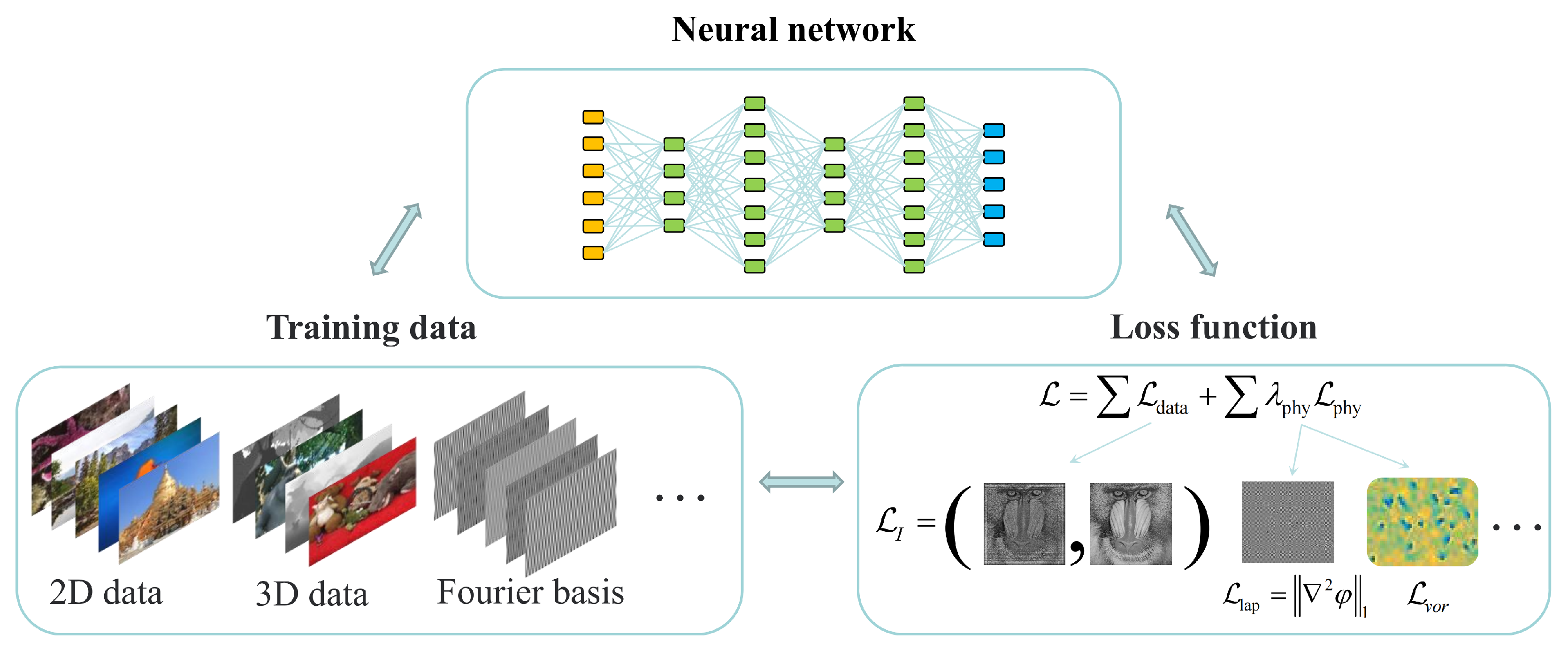
In addition, deep learning has recently played an increasingly important role in computer holography [23,98,103,104,105,106]. Neural networks are typically used to replace the diffraction computation process, enabling hologram generation through model training. Once trained, the model can rapidly generate holograms, facilitating real-time holographic display. The quality of holograms generated by deep learning approaches is primarily influenced by three key factors: neural network, training data, and the loss function, as illustrated in Figure 7. Integrating neural networks with physical constraints—derived from problem-specific analysis—can significantly enhance network performance. For neural network models, supervised learning frameworks are trained using paired holograms and their corresponding reconstructed fields [107]. However, these reconstructions often contain noise, which may be unintentionally learned by the network, thereby degrading its reconstruction quality. In contrast, self-supervised learning frameworks allow the embedding of physical processes as constraints, guiding the network toward more physically plausible solutions [108,109]. The selection of appropriate training datasets is also critical for improving generalization and reconstruction quality. Shi et al. constructed a 3D computational holography dataset, MIT-CGH-4K, which significantly improved 3D holographic display quality [107]. A training dataset composed of Fourier basis functions was proposed, leveraging the spatial frequency characteristics of images to accelerate convergence and enhance generalization [110]. The loss function in deep learning-based holography is highly flexible. In addition to data matching terms, physics-based constraints may also be incorporated to guide the optimization process. For example, a Laplacian-based regularization term L lap = 2 ϕ 1 has been introduced, which encourages smooth phase variations and suppresses speckle noise [111]. Zhu et al. introduced two regularization terms: L Vor , based on the physical structure of phase vortices, and L W , a masked intensity constraint informed by image content [112]. These physics-informed terms help mitigate phase singularities and significantly enhance the quality of the reconstructed holographic images.

4. Modulation Device Noise

In holographic systems, the modulation device is the core component for optical field control and serves as a critical bridge between numerical computation and physical reconstruction [113,114,115,116]. However, due to their physical modulation mechanisms, these devices inherently introduce various types of noise, which can significantly degrade the quality of the reconstructed optical fields. This section outlines the typical types of noise and reviews corresponding methods developed for their suppression.
Most current modulators are incapable of performing arbitrary modulation over the entire complex plane, as illustrated in Figure 8a. Instead, their modulation states are constrained to specific subsets or loci determined by the physical characteristics of the device, as illustrated in Figure 8. According to the modulation mechanism, modulators can be categorized into amplitude, phase modulators, and complex-amplitude. Amplitude modulators, such as the Digital Micromirror Device (DMD), typically provide two discrete points on the real axis, namely 0 (off) and 1 (on), as shown in Figure 8b. Phase modulators are the most widely used, with diverse forms and functionalities. Binary phase modulators, such as the ferroelectric liquid crystal spatial light modulator (FC-SLM), are constrained to two phase states, usually 0 and π , corresponding to 1 and 1 on the complex plane, as shown in Figure 8c. Multi-level phase modulators implement stepped phase modulation with a finite number of discrete phase levels, corresponding to uniformly spaced points on the unit circle, as shown in Figure 8d. Diffractive Optical Elements (DOEs) are a representative example of such devices. Continuous phase modulators, primarily represented by Liquid Crystal on Silicon (LCOS) spatial light modulators, typically achieve 256-level phase modulation, with modulation states uniformly distributed along the unit circle, as shown in Figure 8e. Although metasurfaces enable efficient approximation of complex-amplitude modulation, their reliance on lookup-table-based designs typically results in a constrained modulation space and reduced modulation fidelity. Each device has its own advantages in modulation accuracy, response speed, power consumption, and diffraction efficiency, yet all face common noise issues including high diffraction orders, quantization noise, zero-order components, and modulation errors.

4.1. High Diffraction Order Noise

In the conventional diffraction calculations, the optical field is often assumed to be a continuous complex amplitude distribution, as illustrated in Figure 9a. However, in practical systems, pixelated modulators produce discretized fields, as illustrated in Figure 9b. For a modulator with pixel size Δ x and Δ y , illuminating a normally incident plane wave, the modulated complex amplitude field u pix can be expressed as:
u pix ( x , y ) = u con ( x , y ) m = + n = + δ ( x m Δ x , y n Δ y ) p x , y ,
where u con is the ideally continuous field distribution, δ is sampling function, and p x , y = rect x / Δ x rect y / Δ y . The Fourier spectrum U 2 ( f x , f y ) of the field after propagating a distance z in free space is given by
U 2 f x , f y = U con f x , f y m = + m = + δ f x m Δ x , f y n Δ y P f x , f y H f x , f y ,
where U con and P are the Fourier transforms of u con and p, respectively, and H denotes the transfer function of free-space diffraction propagation.
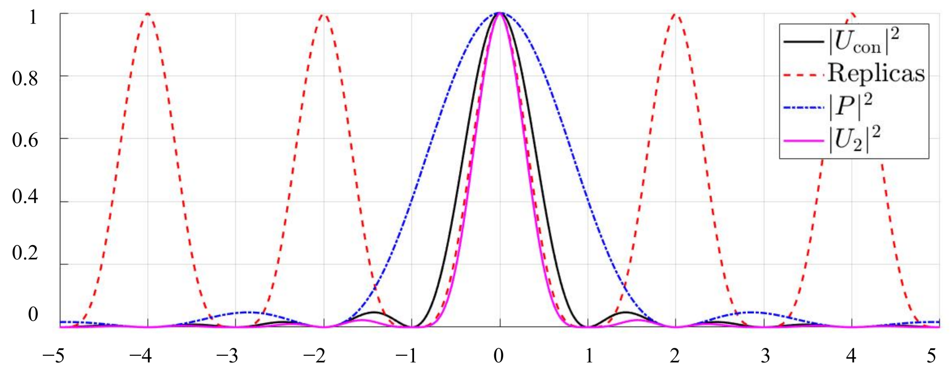
Taking u con ( x ) = rect ( x / L ) as an example, the corresponding spatial frequency spectrum U con ( f x ) becomes a sinc function, and the black solid line in Figure 10 shows the normalized spectral intensity | U con ( f x ) | 2 . Due to the pixelated structure of the hologram, the frequency spectrum U con ( f x ) is replicated by convolution with a sampling function, leading to the generation of higher diffraction orders, as illustrated by the red dashed line in Figure 10. Additionally, due to the finite pixel size, the spectrum is multiplied by a sinc envelope P ( f x ) , which is shown as the blue dashed line in Figure 10. When z = 0 , the transfer function H = 1 , and the normalized spectral intensity of the optical field, | U 2 | 2 , is depicted by the pink solid line in Figure 10. It is not only periodically replicated but also modulated by a sinc envelope. Since the diffraction orders are spatially separated in the frequency domain, the influence of higher-order diffraction components on the reconstruction is significantly reduced in Fourier holography. However, in free-space propagation, these higher-order diffraction components may not be sufficiently separated angularly from the desired constructed field (0th order). Consequently, multiple orders can spatially overlap, leading to crosstalk, artifacts, and a reduction in image fidelity, particularly at short propagation distances. Most existing approaches suppress it using 4f filtering, which increases system complexity. Some methods attempt to suppress it through compact system designs by employing specialized filters. However, their effectiveness is generally limited to specific conditions [117,118,119]. Time-division multiplexing is utilized to control multiple diffraction orders, thereby expanding the space-bandwidth product at the expense of higher system complexity [120]. By applying angular spectrum propagation with frequency-domain padding, the propagation behavior of pixelated spatial light modulators at finite distances can be accurately modeled. High-quality reconstructions can be achieved without additional filtering by performing joint optimization across multiple diffraction orders [121,122].

4.2. Quantization Noise

In CGH, the ideal phase and amplitude distributions are continuous, but as previously discussed, modulation devices can only realize a limited number of discrete levels. Therefore, the continuous phase or amplitude values must be quantized into a finite set of discrete levels, a process known as quantization. This introduces quantization errors at each pixel, which in turn lead to noise in the reconstructed optical fields. As shown in Figure 11, when the continuous phase distribution obtained by the GS algorithm is quantized to 1-bit, 2-bit, 4-bit, and 8-bit levels, the reconstruction quality varies significantly. It is evident that lower quantization bit depths result in more pronounced noise and degradation in reconstruction quality. Therefore, it is essential to consider quantization noise, particularly at low bit depths.
A considerable amount of research has been conducted to analyze the impact of quantization noise on the quality of the reconstructed field and proposed suppression techniques [56,123,124,125,126,127]. Quantization noise can be mitigated either during the hologram generation process by explicitly considering quantization effects, or through temporal averaging method during the modulation stage. Hologram generation methods that take quantization into account can generally be categorized into non-iterative and iterative approaches. Non-iterative methods, such as error diffusion, down-sampling, and wavelet-transform techniques, reduce computational complexity but often result in poor reconstruction quality [72,128,129,130,131,132]. Iterative methods, primarily based on alternating projections, incorporate quantization into each iteration by gradually enforcing discrete constraints on the phase or amplitude [56,133,134,135]. For instance, Wyrowski proposed a gradual discretization strategy for optimizing holograms, in which the iterative process is divided into multiple stages [136], as illustrated in Figure 12. In each stage, phase values that are close to the target discrete levels (indicated in yellow in Figure 12) are quantized accordingly, while intermediate values (shown in blue) remain unchanged. The discretization threshold is progressively expanded in subsequent iterations until full discretization is achieved. However, iterative methods typically achieve better denoising performance at the cost of increased computational complexity. To address this issue, quantization noise was incorporated directly into neural network frameworks [137]. However, reconstruction quality still requires further improvement. Additionally, quantization noise can be suppressed through temporal sequence optimization, as shown in Figure 13. Instead of optimizing a single hologram, a set of holograms is jointly optimized by minimizing the loss function computed on the accumulated reconstructed image over time [138,139]. In conventional temporal averaging, N mutually uncorrelated holograms are simply averaged, leading to a speckle contrast reduction rate of 1 / N . In contrast, temporal sequence optimization accelerates convergence and further improves reconstruction quality by jointly optimizing the hologram sequence.

4.3. Zero-Order Noise

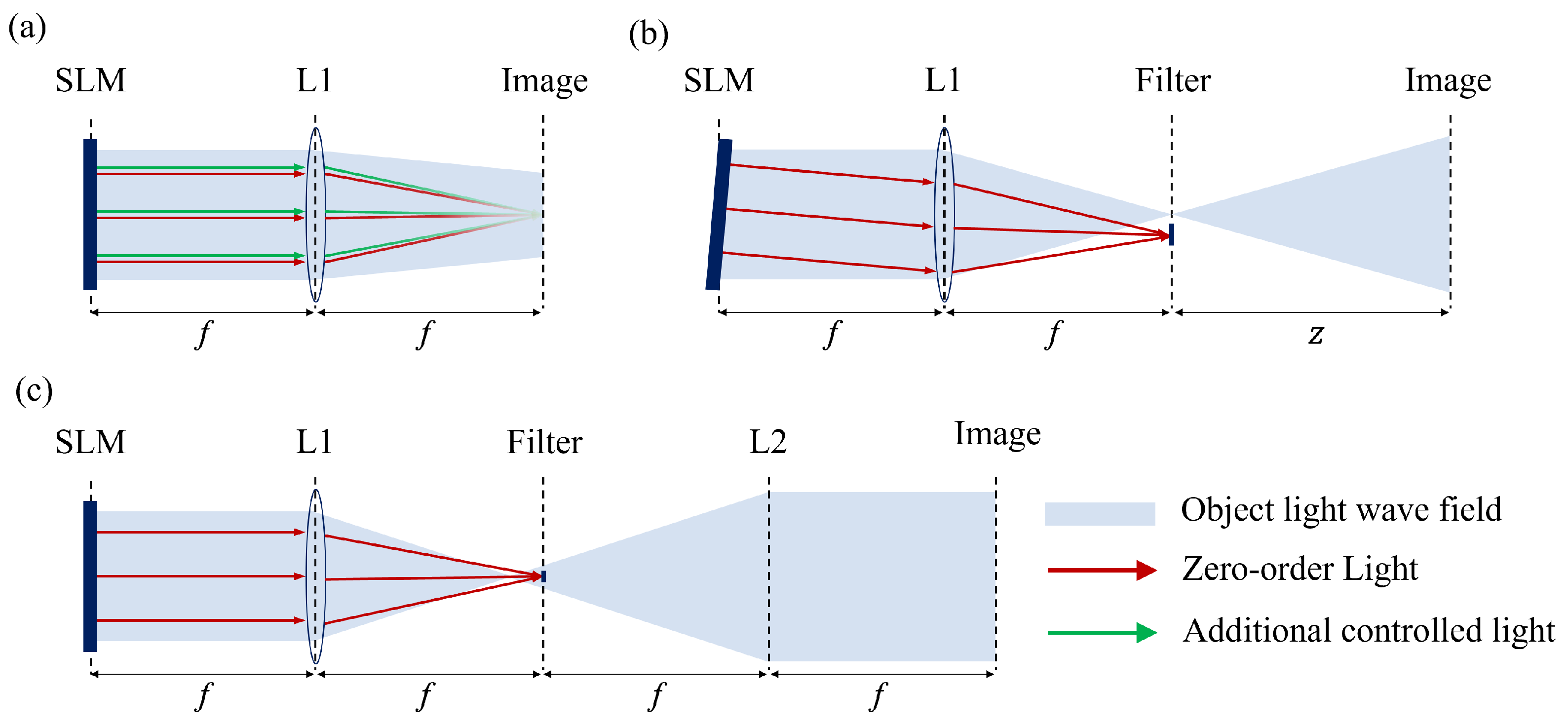
The mechanisms underlying zero-order noise vary depending on the characteristics of the modulation device. For amplitude modulators, since the amplitude can only take positive real values, a constant bias must be added during encoding, which is a major cause of the zero-order component [62,140]. For phase modulators, zero-order noise primarily arises from non-ideal phase modulation responses and dead zones between pixels, where phase cannot be correctly modulated [141,142]. The dead zones, also referred to as pixel gaps or inactive regions, result from the physical spacing between adjacent electrodes on the SLM surface. Since these regions do not modulate the incident wavefront as intended, they act as transparent or reflective areas depending on the device structure, thereby introducing zero-order noise in the reconstructed field. In addition, the architectural choice of the system affects the form of the zero-order noise. In Fresnel holography, it appears as a static background, while in Fourier holography, it presents as a bright central spot. Zero-order noise suppression methods can be broadly classified into three categories: destructive interference, off-axis spatial filtering, and on-axis spatial filtering. In the destructive interference method, the optical field generated by the hologram includes not only the reconstructed object wave but also an additional beam designed to destructively interfere with the zero-order component [143,144,145,146], as illustrated in Figure 14a. This method can simplify system design but typically suffers from limited general applicability. The off-axis method introduces a linear grating phase to shift the reconstructed field away from the optical axis, allowing the zero-order component to be spatially filtered out [147,148,149,150], as shown in Figure 14b. Although this method is widely used due to its simplicity, it inevitably reduces the usable space-bandwidth product of the system. The on-axis method applies a spherical phase to the hologram, separating the zero-order and object wave along the z-axis so that the zero-order can be physically blocked by a filter [151,152,153,154,155], as illustrated in Figure 14c. This approach improves the efficiency of space-bandwidth product utilization; however, the physical filter placed along the optical axis may introduce undesired interference to the reconstructed signal.

4.4. Modulation Errors

Modulation devices often deviate from ideal phase or amplitude responses due to design limitations and physical constraints, resulting in modulation inaccuracies. The factors affecting modulation accuracy are diverse and depend on the type of device and its operating mechanism. For instance, in DOEs and metasurfaces, fabrication errors have a direct impact on modulation accuracy, while in LCOS, the relationship between drive voltage and phase response is nonlinear and varies from device to device. As a result, a lookup table (LUT) is often required to linearize the phase response [156,157,158,159,160], as illustrated in Figure 15a. Furthermore, variations in the driving voltage can cause phase fluctuations in LCOS, as shown in Figure 15b. When digital driving is employed, the signal only switches between two voltage levels, and the phase is modulated using pulse-width modulation (PWM). This results in fluctuations around the target phase. In contrast, analog driving relies on continuously variable voltage levels to control the phase, making phase fluctuations negligible. In addition to these device-specific issues, several common sources of error—such as pixel nonuniformity and device-level crosstalk—can affect a wide range of modulation technologies [161,162,163]. For example, Figure 15c illustrates pixel nonuniformity caused by surface profile variations in LCOS devices. A significant body of work has focused on characterizing the modulation accuracy of modulators and proposing effective approaches to mitigate related inaccuracies [126,164,165].

5. Coherent Noise

Illumination sources are another crucial component in holographic systems. According to the fundamental principles of computer holography, a highly coherent laser is required as the illumination source, which inevitably introduces coherent noise during optical reconstruction [35,52,166]. The characteristics of coherent noise depend on the phase distribution of the reconstructed field. Rapid phase variations, as seen with random phase distributions, typically lead to speckle noise. In contrast, slowly varying phase distributions, such as constant or quadratic phases, often result in Gibbs artifacts, which are also known as ringing artifacts.

5.1. Speckle Noise

Random phase distributions are often applied to target objects in CGH to simulate diffuse reflection. This process helps spread the object information over the entire hologram, maximizing spatial frequency utilization and avoiding loss of detail during reconstruction [167]. However, when a signal is composed of many independent complex-amplitude components, speckle patterns tend to emerge, which can be interpreted as a complex-amplitude random walk [168]. Figure 16 illustrates how 50 unit-amplitude spherical waves, originating from random positions on the hologram plane, coherently superimpose at a point P on the reconstructed field. In Figure 16a, each blue vector represents the complex amplitude contributed by an individual spherical wave at point P. Due to the random distribution of source positions, the corresponding phases are also randomly distributed. The red vector denotes the total complex amplitude resulting from the coherent addition of all spherical waves. As more waves are added, the complex amplitude at the point P traces out a random walk in the complex plane. Figure 16b shows the evolution of the intensity distribution on the reconstructed field as more spherical waves are coherently superposed. As the number of spherical waves increases, speckle patterns gradually emerge and become more pronounced. This suggests that speckle tends to occur more readily when the phase distribution is highly random or varies rapidly. A variety of techniques have been developed to suppress speckle noise, which can be broadly categorized into time averaging, pixel separation, temporal coherence destruction, and phase constraint techniques. The time-averaging method suppresses speckle by sequentially displaying multiple holograms with different phase distributions on the SLM [139,169,170,171]. Since speckle noise exhibits strong randomness, whereas the signal is stable, temporal averaging enhances the signal-to-noise ratio. This approach is simple to implement and can be combined with other algorithms, but it requires a sufficiently high refresh rate of the SLM. The pixel separation method divides the target object into spatially separated pixel groups, each generated into a different hologram [172,173,174]. These holograms are then sequentially displayed to reconstruct the full reconstructed field. By increasing the spacing between adjacent object pixels, this method reduces destructive interference among neighboring points, thereby suppressing speckle noise. However, it also requires a high refresh rate of the SLM. In addition, speckle noise can be reduced by destroying the temporal coherence of the light source. Many studies have employed partially coherent light sources, such as light-emitting diodes (LEDs), for reconstruction [175,176,177,178]. However, reduced coherence can compromise reconstruction sharpness and depth of field, which degrades the overall reconstruction quality. The influence of partially coherent light on reconstruction resolution and speckle contrast was analyzed through a theoretical model [179]. Although this method enhances resolution, speckle noise remains difficult to eliminate. A forward propagation model based on partially coherent illumination was proposed and combined with a CITL framework [180]. Nevertheless, this method imposes constraints on source coherence and still suffers from residual speckle. Furthermore, some studies have attempted to suppress speckle noise by incorporating additional optical components, such as fast-scanning micromirrors, moving diffusers, gradient-structured prisms, deformable mirrors, and rotating DOEs [181,182,183,184,185,186].
As previously analyzed, speckle noise arises from rapid phase variations and excessive randomness. Therefore, some methods limit the phase distribution to suppress speckle noise. Constant or quadratic phase distribution are smooth and can effectively reduce speckle [77,147,167,187,188], but often introduce Gibbs artifacts in the reconstructed fields [189]. Gradient-constrained pseudo-random phase patterns were proposed [190]. By controlling the rate of phase variation, they reduce speckle while improving the utilization of spatial bandwidth. Building on this, frequency-domain optimized pseudo-random phases have been developed to further enhance reconstruction quality [191]. Moreover, since the bandwidth of the hologram is limited, the bandwidth of the reconstructed field intensity is also constrained. The bandwidth characteristics of speckle noise in the reconstructed field were analyzed, and a phase hologram optimization method based on a bandwidth constraint strategy was proposed to effectively suppress speckle [55].

5.2. Gibbs Artifacts

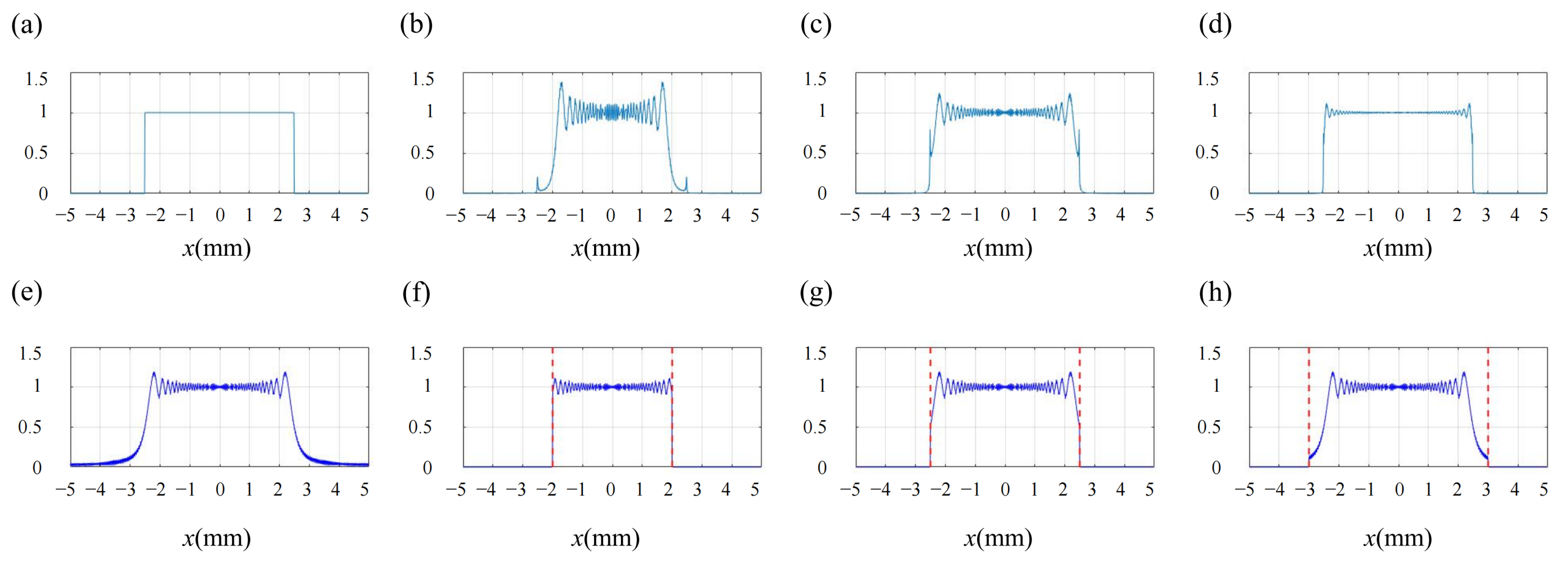
Although smooth phase distributions in holograms can effectively suppress speckle noise, they often result in Gibbs artifacts in the reconstructed field, due to the hard truncation of the spatial frequency spectrum [155,192,193]. The Gibbs phenomenon refers to the oscillatory behavior that occurs near discontinuities when approximating a function using a finite number of terms in its Fourier series. In holographic reconstruction, when the target reconstructed field is confined to a finite spatial region (e.g., a rectangular window), abrupt intensity transitions at the boundaries lead to discontinuities, which in turn cause Gibbs artifacts. Using the Fresnel diffraction of a rectangular window function as an example, the effect of frequency truncation on Gibbs artifacts is illustrated in Figure 17. Figure 17a shows the target reconstructed field, and Figure 17e presents the amplitude distribution of the complex wavefront on the hologram plane. Due to the finite size of the hologram, the wavefront is subject to hard truncation by the hologram window. When the hologram sizes are set to 4 mm, 5 mm, and 6 mm, the corresponding reconstructed fields are shown in Figure 17b–d. Figure 17f–h show the amplitude distributions of the complex amplitude on the hologram plane corresponding to each case. It can be observed that the hard truncation in the frequency domain causes Gibbs artifacts. As the hologram size increases, more frequency components contribute to the reconstruction, resulting in less noticeable Gibbs artifacts. In earlier studies, the underlying mechanisms behind these artifacts were not well understood and Gibbs artifacts were typically suppressed using alternating projection methods [194,195]. However, these approaches disrupted the smooth phase distribution on the hologram plane, resulting in significant speckle noise. It was observed that Gibbs artifacts tended to appear similarly in target reconstructed fields with the same geometric outline [196]. This observation enabled suppression of Gibbs artifacts by subtracting precomputed patterns derived from a reference reconstructed field with a uniform amplitude distribution. However, the effectiveness of this method was limited, with residual Gibbs artifacts present in the reconstructed field. Subsequently, Chen et al. found that reducing the spatial extent of complex amplitude on the hologram plane could help suppress Gibbs artifacts [197]. Nagahama et al. found that such artifacts originated from the leakage of the complex amplitude field beyond the physical boundaries of the hologram [189]. These phenomena were later revealed to be manifestations of the Gibbs phenomenon, and a bandwidth-constrained hologram optimization algorithm was proposed [155]. By iteratively optimizing, frequency components outside the hologram spatial extent are gradually shifted into the hologram size range, effectively eliminating artifact noise.

6. Optical System Noise

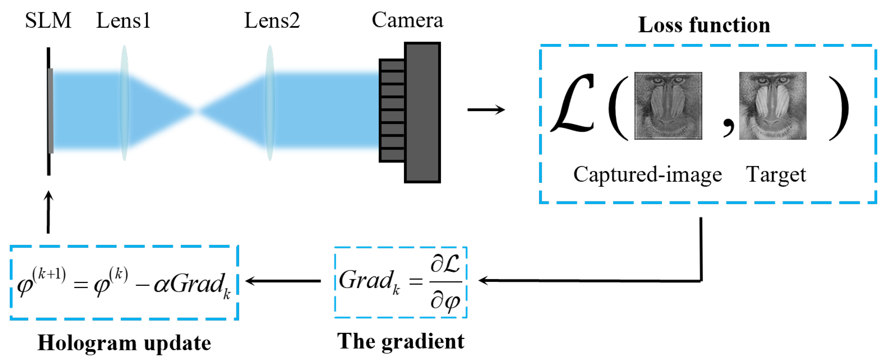
The optical system for light field reconstruction typically begins with a laser source, which must be shaped into the desired incident beam—such as a plane wave or a Gaussian beam. This incident light then illuminates the modulation device, where it is modulated and subsequently transmitted or reflected. The modulated light field propagates through an optical system designed to meet specific requirements, ultimately forming an image on a camera sensor or the human eye. There are numerous noise sources in an optical system, such as non-uniform illumination, aberrations and distortions introduced by lenses, misalignment between multiple modulation devices, and stray light caused by surface imperfections or dust contamination. The complexity and diversity of these noise sources bring significant challenges for accurate modeling and quantitative analysis, resulting in a notable discrepancy between the practical light propagation and the ideal model. To address this issue, Hardware-in-the-Loop (HITL) was proposed [198]. A large number of reconstructed images are captured, and neural network algorithms are employed to learn the difference between simulation results and physical reconstructions to enhance reconstruction quality. However, HITL is an offline method and its learning capability is limited. A Camera-in-the-Loop (CITL) algorithm was proposed, which effectively suppressed system noise by integrating real-time camera feedback into the hologram generation process [98]. The CITL is carried out within a non-convex optimization framework, as illustrated in Figure 18. An initial hologram is uploaded to the SLM, and the camera captures the reconstructed image at the target plane. Unlike traditional approaches, the loss function is calculated based on the difference between the camera-captured image and the target image. Subsequently, the gradient of the loss function with respect to the hologram phase is computed, and the phase is iteratively updated using SGD.
The CITL method effectively suppresses system noise and offers flexibility for further adaptation, which has inspired numerous follow-up studies. For example, the forward propagation model can be adjusted to better match the physical system, and additional physics-based regularization terms can be added to the loss function. To suppress the speckle noise, Peng et al. employed a partially coherent light source, developed a diffraction model for partially coherent illumination, and combined it with the CITL for optimization [180]. A diffraction model from a single plane to multiple planes was constructed by combining the ASM with Convolutional Neural Networks (CNNs), enabling three-dimensional near-eye displays [111]. The high-order joint optimization algorithm was proposed and subsequently integrated with the CITL, further enhancing reconstruction quality [121]. In addition, to suppress the zero-order noise, Michelson Holography (MH) was proposed, which uses undiffracted light from two SLMs to generate destructive interference [199]. When combined with the CITL, it avoids the need for explicit modeling of the undiffracted light but requires a relatively complex system configuration. An off-axis optimization method based on the CITL was proposed, which offers a more simplified system [149]. To reduce the noise caused by the discrepancy between the ideal and physical propagation models, Gaussian blurring was applied to both simulated reconstruction and camera-captured image before computing the loss. This strategy improves reconstruction quality and accelerates convergence. Moreover, numerous subsequent works have been developed based on the CITL to enhance the quality of holographic reconstruction [200,201,202]. Overall, the outstanding noise suppression capabilities of CITL demonstrate its strong potential for practical holographic display applications.

7. Future Outlook

In recent years, computational holography has made remarkable progress in both algorithmic innovation and system-level integration. A variety of effective strategies have been developed to improve reconstruction quality and suppress noise across different stages of the CGH pipeline. These advances have greatly expanded the potential applications of computer holography in optical manipulation, micro-/nanofabrication, and high-resolution three-dimensional displays. Despite significant progress, achieving high-quality, noise-free holographic reconstruction remains a central challenge in computer holography. Based on the comprehensive analysis of current methods and challenges presented in this review, we summarize several important and emerging research directions, particularly centered on improving reconstruction fidelity and mitigating various sources of noise in computational holography.
Accurate, efficient, and flexible diffraction modeling remains a fundamental topic in computational holography. As the basis of hologram generation and reconstruction, diffraction calculation has been extensively explored, and various numerical methods have been widely applied. However, balancing physical accuracy with computational efficiency remains a key challenge, particularly for high-resolution and real-time applications. In addition, the applicability of traditional diffraction models is often limited to specific assumptions or simplified conditions. Extending these models to handle more diverse scenarios—such as non-paraxial systems or wave propagation through complex media—will be essential for supporting next-generation holographic systems.
Further progress is needed in analyzing diffraction characteristics and performing error calibration of current modulators, as well as in developing improved modulation devices. Accurate characterization and calibration of device-induced noise—such as higher-order diffractions, zero-order leakage, conjugate images, and pixel crosstalk—remain critical for improving reconstruction quality. On the other hand, innovations in modulator technology—such as higher resolution, faster response, greater phase stability, and novel modulation mechanisms—are essential to push the boundaries of holographic display quality.
At the system level, various sources of noise from the optical setup, light source, and the modulation device can significantly degrade reconstruction quality. Recently, the CITL method has emerged as a promising approach to directly compensate for system-level imperfections by incorporating the physical hardware into the optimization process. This framework has demonstrated the ability to simultaneously address multiple types of noise without requiring explicit modeling of each source. Nevertheless, a clear understanding of the underlying noise sources remains essential, as current CITL pipelines still rely on simulated models to compute the gradients required for optimization. The accuracy of these gradients depends on how well the simulation model approximates the actual behavior of the optical system. Therefore, continued efforts in system noise analysis and physically accurate modeling will be crucial for improving the robustness, convergence, and reconstruction fidelity of CITL-based methods.
Breakthroughs in optimization algorithms also play a pivotal role in improving holographic reconstruction quality. Gradient-based optimization methods have shown great potential, particularly when combined with tailored loss functions designed for different objectives—such as enhancing perceptual quality, enforcing physical constraints, or suppressing specific types of noise. These formulations not only expand the solution space but also provide greater flexibility in addressing diverse reconstruction challenges. In parallel, deep learning approaches have advanced rapidly, offering noise removal capabilities and the ability to generate holograms with high speed and flexibility. While data-driven methods can deliver impressive results, they still face challenges in generalization, interpretability, and consistency with physical models. Future research may benefit from hybrid strategies that integrate the precision and controllability of physics-based optimization with the efficiency and adaptability of learning-based techniques.
In summary, continued progress in computational holography will depend on interdisciplinary efforts that span algorithm design, physical modeling, device engineering, and system-level integration. Addressing the multifaceted sources of noise and distortion requires not only isolated technical improvements, but also coordinated advances across the entire computational imaging pipeline. By combining physical insights with modern optimization and learning tools, the field is poised to achieve more robust, high-fidelity, and practical holographic solutions in the coming years.

8. Conclusions

This paper presents a systematic review of the primary sources of noise in computer holography and the strategies developed to suppress noise. Following the reconstruction pipeline of CGH systems, we categorized the noise sources into four main types: (1) inaccuracies in diffraction calculations, (2) algorithm-induced noise from encoding and optimization methods, (3) noise originating from modulation devices, (4) coherent noise caused by coherent light sources and (5) optical system noise stemming from imperfections in the optical setup. For each category, we explored the underlying physical mechanisms of noise generation, identified key factors influencing noise levels, and provided a comprehensive review of representative methods proposed for noise suppression. It is important to emphasize that these noise sources are not mutually independent. In many cases, a single algorithm or system design may simultaneously affect multiple noise types. Therefore, achieving high-quality holographic reconstruction requires a holistic approach that considers noise across the entire CGH pipeline. Emerging solutions, such as deep learning-based holography and CITL optimization, demonstrate promising directions in this regard. By clarifying the origin, characteristics, and impact of various noise sources, this review aims to serves as a reference for researchers to analyze the noise in their own methods and to design more robust and efficient CGH systems. We hope this work can serve as a guideline for enhancing reconstruction fidelity and facilitating the systematic design of CGH systems.

Author Contributions

Conceptualization, S.T. and H.Z.; methodology, S.T.; software, S.T. and Z.F.; validation, S.T. and H.Z.; formal analysis, S.T., Z.F. and H.Z.; investigation, S.T. and Z.F.; resources, H.Z.; writing—original draft preparation, S.T.; writing—review and editing, S.T. and Z.F.; visualization, S.T. and Z.F.; supervision, H.Z., Q.T. and L.S.; project administration, H.Z., Q.T. and L.S.; funding acquisition, H.Z. All authors have read and agreed to the published version of the manuscript.

Funding

This research was funded by National Natural Science Foundation of China (62035003).

Institutional Review Board Statement

Not applicable.

Informed Consent Statement

Not applicable.

Data Availability Statement

No new data were created or analyzed in this study.

Conflicts of Interest

The authors declare no conflicts of interest.

References

  1. Gabor, D. A new microscopic principle. Nature 1948, 161, 777–778. [Google Scholar] [CrossRef]
  2. Leith, E.N.; Upatnieks, J. Reconstructed wavefronts and communication theory. J. Opt. Soc. Am. 1962, 52, 1123–1130. [Google Scholar] [CrossRef]
  3. Leith, E.N.; Upatnieks, J. Wavefront reconstruction with continuous-tone objects. J. Opt. Soc. Am. 1963, 53, 1377–1381. [Google Scholar] [CrossRef]
  4. Leith, E.N.; Upatnieks, J. Wavefront reconstruction with diffused illumination and three-dimensional objects. J. Opt. Soc. Am. 1964, 54, 1295–1301. [Google Scholar] [CrossRef]
  5. Javidi, B.; Carnicer, A.; Anand, A.; Barbastathis, G.; Chen, W.; Ferraro, P.; Goodman, J.W.; Horisaki, R.; Khare, K.; Kujawinska, M.; et al. Roadmap on digital holography. Opt. Express 2021, 29, 35078–35118. [Google Scholar] [CrossRef]
  6. Lohmann, A.W.; Weigelt, G.; Wirnitzer, B. Speckle masking in astronomy: Triple correlation theory and applications. Appl. Opt. 1983, 22, 4028–4037. [Google Scholar] [CrossRef] [PubMed]
  7. Bartelt, H.; Lohmann, A.W.; Wirnitzer, B. Phase and amplitude recovery from bispectra. Appl. Opt. 1984, 23, 3121–3129. [Google Scholar] [CrossRef] [PubMed]
  8. Lohmann, A.W.; Paris, D.P. Binary Fraunhofer holograms, generated by computer. Appl. Opt. 1967, 6, 1739–1748. [Google Scholar] [CrossRef]
  9. Brown, B.R.; Lohmann, A.W. Complex spatial filtering with binary masks. Appl. Opt. 1966, 5, 967–969. [Google Scholar] [CrossRef]
  10. Lesem, L.B.; Hirsch, P.M.; Jordan, J.A., Jr. Scientific applications: Computer synthesis of holograms for 3-D display. Commun. ACM 1968, 11, 661–674. [Google Scholar] [CrossRef]
  11. Lesem, L.B.; Hirsch, P.M.; Jordan, J.A. The kinoform: A new wavefront reconstruction device. IBM J. Res. Dev. 1969, 13, 150–155. [Google Scholar] [CrossRef]
  12. Maimone, A.; Georgiou, A.; Kollin, J.S. Holographic near-eye displays for virtual and augmented reality. ACM Trans. Graph. 2017, 36, 1–16. [Google Scholar] [CrossRef]
  13. Jang, C.; Bang, K.; Li, G.; Lee, B. Holographic near-eye display with expanded eye-box. ACM Trans. Graph. 2018, 37, 1–14. [Google Scholar] [CrossRef]
  14. Ren, H.; Briere, G.; Fang, X.; Ni, P.; Sawant, R.; Héron, S.; Chenot, S.; Vézian, S.; Damilano, B.; Brändli, V.; et al. Metasurface orbital angular momentum holography. Nat. Commun. 2019, 10, 2986. [Google Scholar] [CrossRef]
  15. Skirnewskaja, J.; Wilkinson, T.D. Automotive holographic head-up displays. Adv. Mater. 2022, 34, 2110463. [Google Scholar] [CrossRef] [PubMed]
  16. Liu, T.; Ning, H.; Cao, H.; Luo, D.; Xu, Z.; Luo, C.; Su, G.; Liu, Y.; Yao, R.; Peng, J. Research progress of large viewing-area 3D holographic near-eye display. Laser Photonics Rev. 2024, 18, 2300641. [Google Scholar] [CrossRef]
  17. Zhao, N.; Xiao, J.; Weng, P.; Zhang, H. Tomographic waveguide-based augmented reality display. Opt. Express 2024, 32, 18692–18699. [Google Scholar] [CrossRef] [PubMed]
  18. Padgett, M.; Di Leonardo, R. Holographic optical tweezers and their relevance to lab on chip devices. Lab A Chip 2011, 11, 1196–1205. [Google Scholar] [CrossRef] [PubMed]
  19. Dolev, I.; Epstein, I.; Arie, A. Surface-plasmon holographic beam shaping. Phys. Rev. Lett. 2012, 109, 203903. [Google Scholar] [CrossRef]
  20. Otte, E.; Denz, C. Optical trapping gets structure: Structured light for advanced optical manipulation. Appl. Phys. Rev. 2020, 7, 041308. [Google Scholar] [CrossRef]
  21. Zhang, C.; Hu, Y.; Du, W.; Wu, P.; Rao, S.; Cai, Z.; Lao, Z.; Xu, B.; Ni, J.; Li, J.; et al. Optimized holographic femtosecond laser patterning method towards rapid integration of high-quality functional devices in microchannels. Sci. Rep. 2016, 6, 33281. [Google Scholar] [CrossRef] [PubMed]
  22. Xue, G.; Zhai, Q.; Lu, H.; Zhou, Q.; Ni, K.; Lin, L.; Wang, X.; Li, X. Polarized holographic lithography system for high-uniformity microscale patterning with periodic tunability. Microsystems Nanoeng. 2021, 7, 31. [Google Scholar] [CrossRef] [PubMed]
  23. Wetzstein, G.; Ozcan, A.; Gigan, S.; Fan, S.; Englund, D.; Soljačić, M.; Denz, C.; Miller, D.A.B.; Psaltis, D. Inference in artificial intelligence with deep optics and photonics. Nature 2020, 588, 39–47. [Google Scholar] [CrossRef] [PubMed]
  24. Blanche, P.A.; Bablumian, A.; Voorakaranam, R.; Christenson, C.; Lin, W.; Gu, T.; Flores, D.; Wang, P.; Hsieh, W.Y.; Kathaperumal, M.; et al. Holographic three-dimensional telepresence using large-area photorefractive polymer. Nature 2010, 468, 80–83. [Google Scholar] [CrossRef]
  25. Forbes, A.; de Oliveira, M.; Dennis, M.R. Structured light. Nat. Photonics 2021, 15, 253–262. [Google Scholar] [CrossRef]
  26. Bryngdahl, O.; Lee, W.H. Laser beam scanning using computer-generated holograms. Appl. Opt. 1976, 15, 183–194. [Google Scholar] [CrossRef]
  27. Lohmann, A.W.; Thomas, J.A. Making an array illuminator based on the Talbot effect. Appl. Opt. 1990, 29, 4337–4340. [Google Scholar] [CrossRef]
  28. Lee, W.H. Method for converting a Gaussian laser beam into a uniform beam. Opt. Commun. 1981, 36, 469–471. [Google Scholar] [CrossRef]
  29. Makey, G.; Yavuz, Ö.; Kesim, D.K.; Turnalı, A.; Elahi, P.; Ilday, S.; Tokel, O.; Ilday, F.Ö. Breaking crosstalk limits to dynamic holography using orthogonality of high-dimensional random vectors. Nat. Photonics 2019, 13, 251–256. [Google Scholar] [CrossRef]
  30. Sommerfeld, A. Mathematische theorie der diffraction. Math. Ann. 1896, 47, 317–374. [Google Scholar] [CrossRef]
  31. Born, M.; Wolf, E. Principles of Optics: Electromagnetic Theory of Propagation, Interference and Diffraction of Light; Elsevier: Amsterdam, The Netherlands, 2013. [Google Scholar]
  32. Lohmann, A.W. Reconstruction of Vectorial Wavefronts. Appl. Opt. 1965, 4, 1667–1668. [Google Scholar] [CrossRef]
  33. Keller, J.B. Geometrical Theory of Diffraction. In Classical andModern Diffraction Theory; Klem-Musatov, K., Hoeber, H.C., Moser, T.J., Pelissier, M.A., Eds.; Society of Exploration Geophysicists: Houston, TX, USA, 2016. [Google Scholar] [CrossRef]
  34. Lee, W.H. Sampled Fourier Transform Hologram Generated by Computer. Appl. Opt. 1970, 9, 639–643. [Google Scholar] [CrossRef]
  35. Goodman, J.W. Introduction to Fourier Optics; W. H. Freeman, Macmillan Learning: New York, NY, USA, 2017. [Google Scholar]
  36. Voelz, D.G. Computational fourier Optics: A MATLAB Tutorial; SPIE: Bellingham, WA, USA, 2011. [Google Scholar] [CrossRef]
  37. Zhang, W.; Zhang, H.; Jin, G. Frequency sampling strategy for numerical diffraction calculations. Opt. Express 2020, 28, 39916–39932. [Google Scholar] [CrossRef] [PubMed]
  38. Zhang, W.; Zhang, H.; Jin, G. Single-Fourier transform based full-bandwidth Fresnel diffraction. J. Opt. 2021, 23, 035604. [Google Scholar] [CrossRef]
  39. Gori, F. Fresnel transform and sampling theorem. Opt. Commun. 1981, 39, 293–297. [Google Scholar] [CrossRef]
  40. Voelz, D.G.; Roggemann, M.C. Digital simulation of scalar optical diffraction: Revisiting chirp function sampling criteria and consequences. Appl. Opt. 2009, 48, 6132–6142. [Google Scholar] [CrossRef] [PubMed]
  41. Kelly, D.P. Numerical calculation of the Fresnel transform. J. Opt. Soc. Am. A 2014, 31, 755–764. [Google Scholar] [CrossRef]
  42. Shen, F.; Wang, A. Fast-Fourier-transform based numerical integration method for the Rayleigh-Sommerfeld diffraction formula. Appl. Opt. 2006, 45, 1102–1110. [Google Scholar] [CrossRef]
  43. Xiao, Y.; Tang, X.; Qin, Y.; Peng, H.; Wang, W. Wide-window angular spectrum method for diffraction propagation in far and near field. Opt. Lett. 2012, 37, 4943–4945. [Google Scholar] [CrossRef]
  44. Matsushima, K.; Shimobaba, T. Band-limited angular spectrum method for numerical simulation of free-space propagation in far and near fields. Opt. Express 2009, 17, 19662–19673. [Google Scholar] [CrossRef]
  45. Shimobaba, T.; Kakue, T.; Okada, N.; Oikawa, M.; Yamaguchi, Y.; Ito, T. Aliasing-reduced Fresnel diffraction with scale and shift operations. J. Opt. 2013, 15, 075405. [Google Scholar] [CrossRef]
  46. Kim, Y.H.; Byun, C.W.; Oh, H.; Lee, J.; Pi, J.E.; Kim, G.H.; Lee, M.L.; Ryu, H.; Chu, H.Y.; Hwang, C.S. Non-uniform sampling and wide range angular spectrum method. J. Opt. 2014, 16, 125710. [Google Scholar] [CrossRef]
  47. Zhang, W.; Zhang, H.; Jin, G. Band-extended angular spectrum method for accurate diffraction calculation in a wide propagation range. Opt. Lett. 2020, 45, 1543–1546. [Google Scholar] [CrossRef] [PubMed]
  48. Xiao, J.; Zhang, W.; Zhang, H. Sampling analysis for Fresnel diffraction fields based on phase space representation. J. Opt. Soc. Am. A 2022, 39, A15–A28. [Google Scholar] [CrossRef]
  49. Wyrowski, F.; Bryngdahl, O. Iterative Fourier-transform algorithm applied to computer holography. J. Opt. Soc. Am. A 1988, 5, 1058–1065. [Google Scholar] [CrossRef]
  50. Wyrowski, F.; Bryngdahl, O. Speckle-free reconstruction in digital holography. J. Opt. Soc. Am. A 1989, 6, 1171–1174. [Google Scholar] [CrossRef]
  51. Bräuer, R.; Wyrowski, F.; Bryngdahl, O. Diffusers in digital holography. J. Opt. Soc. Am. A 1991, 8, 572–578. [Google Scholar] [CrossRef]
  52. Aagedal, H.; Schmid, M.; Beth, T.; Teiwes, S.; Wyrowski, F. Theory of speckles in diffractive optics and its application to beam shaping. J. Mod. Opt. 1996, 43, 1409–1421. [Google Scholar] [CrossRef]
  53. Qu, W.; Gu, H.; Tan, Q.; Jin, G. Precise design of two-dimensional diffractive optical elements for beam shaping. Appl. Opt. 2015, 54, 6521–6525. [Google Scholar] [CrossRef]
  54. Porfirev, A.P. Modification of the Gerchberg-Saxton algorithm for the generation of specle-reduced intensity distributions of micrometer and submicrometer dimensions. Optik 2019, 195, 163163. [Google Scholar] [CrossRef]
  55. Chen, L.; Tian, S.; Zhang, H.; Cao, L.; Jin, G. Phase hologram optimization with bandwidth constraint strategy for speckle-free optical reconstruction. Opt. Express 2021, 29, 11645–11663. [Google Scholar] [CrossRef] [PubMed]
  56. Wyrowski, F. Iterative quantization of digital amplitude holograms. Appl. Opt. 1989, 28, 3864–3870. [Google Scholar] [CrossRef] [PubMed]
  57. Cohen, L. Time-Frequency Analysis; Prentice-Hall: Englewood Cliffs, NJ, USA, 1995. [Google Scholar]
  58. Burch, J.J. A computer algorithm for the synthesis of spatial frequency filters. Proc. IEEE 1967, 55, 599–601. [Google Scholar] [CrossRef]
  59. Lee, W.H. Binary synthetic holograms. Appl. Opt. 1974, 13, 1677–1682. [Google Scholar] [CrossRef]
  60. Lee, W.H. Binary computer-generated holograms. Appl. Opt. 1979, 18, 3661–3669. [Google Scholar] [CrossRef]
  61. Bryngdahl, O.; Lohmann, A. Single-sideband holography. J. Opt. Soc. Am. 1968, 58, 620–624. [Google Scholar] [CrossRef]
  62. Wang, X.; Zhang, H.; Cao, L.; Jin, G. Generalized single-sideband three-dimensional computer-generated holography. Opt. Express 2019, 27, 2612–2620. [Google Scholar] [CrossRef] [PubMed]
  63. Takahashi, T.; Shimobaba, T.; Kakue, T.; Ito, T. Time-division color holographic projection in large size using a digital micromirror device. Appl. Sci. 2021, 11, 6277. [Google Scholar] [CrossRef]
  64. Li, Z.; Zheng, Y.; Li, Y.; Wang, D.; Wang, Q. Method of color holographic display with speckle noise suppression. Opt. Express 2022, 30, 25647–25660. [Google Scholar] [CrossRef]
  65. Yu, P.; Liu, Y.; Wang, Z.; Liang, J.; Liu, X.; Li, Y.; Qiu, C.; Gong, L. Ultrahigh-density 3D holographic projection by scattering-assisted dynamic holography. Optica 2023, 10, 481–490. [Google Scholar] [CrossRef]
  66. Blanche, P.A.; Ketchum, R.S. Texas instruments phase light modulator for holography. In Proceedings of the Digital Holography and Three-Dimensional Imaging, Washington, DC, USA, 19–23 July 2021; p. DW4B.3. [Google Scholar] [CrossRef]
  67. Barnard, E.; Vermeulen, P.; Casasent, D.P. Optical correlation CGHs with modulated error diffusion. Appl. Opt. 1989, 28, 5358–5362. [Google Scholar] [CrossRef]
  68. Buckley, E. Real-time error diffusion for signal-to-noise ratio improvement in a holographic projection system. J. Disp. Technol. 2011, 7, 70–76. [Google Scholar] [CrossRef]
  69. Tsang, P.W.M.; Poon, T.C. Novel method for converting digital Fresnel hologram to phase-only hologram based on bidirectional error diffusion. Opt. Express 2013, 21, 23680–23686. [Google Scholar] [CrossRef] [PubMed]
  70. Floyd, R.W. An adaptive algorithm for spatial gray-scale. In Proceedings of the Society of In-formation Display, New York, NY, USA, 7–10 June 1976; Volume 17, pp. 75–77. [Google Scholar]
  71. Chang, C.; Xia, J.; Lei, W. Speckle suppression in phase-only holographic display by optimizing phase distribution. In Proceedings of the Digital Holography and Three-Dimensional Imaging, Shanghai China, 24–28 May 2015; p. DW3A.5. [Google Scholar] [CrossRef]
  72. Yang, G.; Jiao, S.; Liu, J.P.; Lei, T.; Yuan, X. Error diffusion method with optimized weighting coefficients for binary hologram generation. Appl. Opt. 2019, 58, 5547–5555. [Google Scholar] [CrossRef] [PubMed]
  73. Jiao, S.; Zhang, D.; Zhang, C.; Gao, Y.; Lei, T.; Yuan, X. Complex-amplitude holographic projection with a digital micromirror device (DMD) and error diffusion algorithm. IEEE J. Sel. Top. Quantum Electron. 2020, 26, 1–8. [Google Scholar] [CrossRef]
  74. Liu, K.; He, Z.; Cao, L. Pattern-adaptive error diffusion algorithm for improved phase-only hologram generation. Chin. Opt. Lett. 2021, 19, 050501. [Google Scholar] [CrossRef]
  75. Omel, M.Y.; Gladys, M.V.; Jesús, L. Encoding complex fields by using a phase-only optical element. Opt. Lett. 2014, 39, 1740–1743. [Google Scholar] [CrossRef]
  76. Qi, Y.; Chang, C.; Xia, J. Speckleless holographic display by complex modulation based on double-phase method. Opt. Express 2016, 24, 30368–30378. [Google Scholar] [CrossRef]
  77. Chang, C.; Qi, Y.; Wu, J.; Xia, J.; Nie, S. Speckle reduced lensless holographic projection from phase-only computer-generated hologram. Opt. Express 2017, 25, 6568–6580. [Google Scholar] [CrossRef]
  78. Kim, Y.K.; Lee, J.S.; Won, Y.H. Low-noise high-efficiency double-phase hologram by multiplying a weight factor. Opt. Lett. 2019, 44, 3649–3652. [Google Scholar] [CrossRef]
  79. Sui, X.; He, Z.; Jin, G.; Chu, D.; Cao, L. Band-limited double-phase method for enhancing image sharpness in complex modulated computer-generated holograms. Opt. Express 2021, 29, 2597–2612. [Google Scholar] [CrossRef]
  80. Shimobaba, T.; Wang, F.; Starobrat, J.; Kowalczyk, A.; Suszek, J.; Ito, T. Comparison of double-phase hologram and binary amplitude encoding: Holographic projection and vortex beam generation. Appl. Opt. 2023, 62, 7471–7479. [Google Scholar] [CrossRef]
  81. Bättig, R.K.; Guest, C.C.; Schaefer, S.R.; Toms, D.J. Simulated annealing of binary holograms for the interconnection of single-mode structures. Appl. Opt. 1992, 31, 1059–1066. [Google Scholar] [CrossRef]
  82. Mahlab, U.; Shamir, J.; Caulfield, H.J. Genetic algorithm for optical pattern recognition. Opt. Lett. 1991, 16, 648–650. [Google Scholar] [CrossRef]
  83. Su, P.; Cai, C.; Song, Y.; Ma, J.; Tan, Q. A hybrid diffractive optical element design algorithm combining particle swarm optimization and a simulated annealing algorithm. Appl. Sci. 2020, 10, 5485. [Google Scholar] [CrossRef]
  84. Chhetri, B.B.; Yang, S.; Shimomura, T. Stochastic approach in the efficient design of the direct-binary-search algorithm for hologram synthesis. Appl. Opt. 2000, 39, 5956–5964. [Google Scholar] [CrossRef] [PubMed]
  85. Gerchberg, R.W.; Saxton, W.O. A practical algorithm for the determination of phase from image and diffraction plane pictures. Optik 1972, 35, 237–246. [Google Scholar]
  86. Fienup, J.R. Reconstruction of an object from modulus of its Fourier transform. Opt. Lett. 1978, 3, 27–29. [Google Scholar] [CrossRef] [PubMed]
  87. Fienup, J.R. Iterative method applied to image reconstruction and to computer-generated holograms. Opt. Eng. 1980, 19, 193297. [Google Scholar] [CrossRef]
  88. Fienup, J.R. Phase retrieval algorithms: A comparison. Appl. Opt. 1982, 21, 2758–2769. [Google Scholar] [CrossRef]
  89. Akahori, H. Spectrum leveling by an iterative algorithm with a dummy area for synthesizing the kinoform. Appl. Opt. 1986, 25, 802–811. [Google Scholar] [CrossRef]
  90. Kuzmenko, A.V. Weighting iterative Fourier transform algorithm of the kinoform synthesis. Opt. Lett. 2008, 33, 1147–1149. [Google Scholar] [CrossRef]
  91. Zhou, P.; Li, Y.; Liu, S.; Su, Y. Dynamic compensatory Gerchberg–Saxton algorithm for multiple-plane reconstruction in holographic displays. Opt. Express 2019, 27, 8958–8967. [Google Scholar] [CrossRef]
  92. Wu, Y.; Wang, J.; Chen, C.; Liu, C.; Jin, F.; Chen, N. Adaptive weighted Gerchberg-Saxton algorithm for generation of phase-only hologram with artifacts suppression. Opt. Express 2021, 29, 1412–1427. [Google Scholar] [CrossRef]
  93. Georgiou, A.; Christmas, J.; Collings, N.; Moore, J.; Crossland, W.A. Aspects of hologram calculation for video frames. J. Opt. A Pure Appl. Opt. 2008, 10, 035302. [Google Scholar] [CrossRef]
  94. Hsu, W.F.; Lin, S.C. Iterative pixelwise approach applied to computer-generated holograms and diffractive optical elements. Appl. Opt. 2018, 57, A189–A196. [Google Scholar] [CrossRef] [PubMed]
  95. Chen, Y.; Chi, Y.; Fan, J.; Ma, C. Gradient descent with random initialization: Fast global convergence for nonconvex phase retrieval. Math. Program. 2019, 176, 5–37. [Google Scholar] [CrossRef] [PubMed]
  96. Ma, C.; Wang, K.; Chi, Y.; Chen, Y. Implicit Regularization in Nonconvex Statistical Estimation: Gradient Descent Converges Linearly for Phase Retrieval and Matrix Completion. In Proceedings of the 35th International Conference on Machine Learning, Stockholm, Sweden, 10–15 July 2018; In Proceedings of Machine Learning Research. Dy, J., Krause, A., Eds.; PMLR: Stockholm, Sweden, 2018; Volume 80, pp. 3345–3354. [Google Scholar]
  97. Chakravarthula, P.; Peng, Y.; Kollin, J.; Fuchs, H.; Heide, F. Wirtinger holography for near-eye displays. ACM Trans. Graph. 2019, 38, 1–13. [Google Scholar] [CrossRef]
  98. Peng, Y.; Choi, S.; Padmanaban, N.; Wetzstein, G. Neural holography with camera-in-the-loop training. ACM Trans. Graph. 2020, 39, 1–14. [Google Scholar] [CrossRef]
  99. Wang, D.; Li, N.; Li, Y.; Zheng, Y.; Wang, Q. Curved hologram generation method for speckle noise suppression based on the stochastic gradient descent algorithm. Opt. Express 2021, 29, 42650–42662. [Google Scholar] [CrossRef]
  100. Chen, C.; Lee, B.; Li, N.; Chae, M.; Wang, D.; Wang, Q.; Lee, B. Multi-depth hologram generation using stochastic gradient descent algorithm with complex loss function. Opt. Express 2021, 29, 15089–15103. [Google Scholar] [CrossRef]
  101. Yang, F.; Kadis, A.; Mouthaan, R.; Wetherfield, B.; Kaczorowski, A.; Wilkinson, T.D. Perceptually motivated loss functions for computer generated holographic displays. Sci. Rep. 2022, 12, 7709. [Google Scholar] [CrossRef] [PubMed]
  102. Zhang, J.; Pégard, N.; Zhong, J.; Adesnik, H.; Waller, L. 3D computer-generated holography by non-convex optimization. Optica 2017, 4, 1306–1313. [Google Scholar] [CrossRef]
  103. Horisaki, R.; Takagi, R.; Tanida, J. Deep-learning-generated holography. Appl. Opt. 2018, 57, 3859–3863. [Google Scholar] [CrossRef]
  104. Barbastathis, G.; Ozcan, A.; Situ, G. On the use of deep learning for computational imaging. Optica 2019, 6, 921–943. [Google Scholar] [CrossRef]
  105. Rivenson, Y.; Wu, Y.; Ozcan, A. Deep learning in holography and coherent imaging. Light. Sci. Appl. 2019, 8, 85. [Google Scholar] [CrossRef]
  106. Cheremkhin, P.A.; Rymov, D.A.; Svistunov, A.S.; Zlokazov, E.Y.; Starikov, R.S. Neural-network-based methods in digital and computer-generated holography: A review. J. Opt. Technol. 2024, 91, 170–180. [Google Scholar] [CrossRef]
  107. Shi, L.; Li, B.; Kim, C.; Kellnhofer, P.; Matusik, W. Towards real-time photorealistic 3D holography with deep neural networks. Nature 2021, 591, 234–239. [Google Scholar] [CrossRef]
  108. Wu, J.; Liu, K.; Sui, X.; Cao, L. High-speed computer-generated holography using an autoencoder-based deep neural network. Opt. Lett. 2021, 46, 2908–2911. [Google Scholar] [CrossRef]
  109. Liu, K.; Wu, J.; He, Z.; Cao, L. 4K-DMDNet: Diffraction model-driven network for 4K computer-generated holography. Opto-Electron. Adv. 2023, 6, 220135. [Google Scholar] [CrossRef]
  110. Zhu, R.; Chen, L.; Zhang, H. Computer holography using deep neural network with Fourier basis. Opt. Lett. 2023, 48, 2333–2336. [Google Scholar] [CrossRef]
  111. Choi, S.; Gopakumar, M.; Peng, Y.; Kim, J.; Wetzstein, G. Neural 3D holography: Learning accurate wave propagation models for 3D holographic virtual and augmented reality displays. ACM Trans. Graph. 2021, 40, 1–12. [Google Scholar] [CrossRef]
  112. Zhu, R.; Chen, L.; Xiao, J.; Zhang, H. Three-dimensional computer holography with phase space tailoring. PhotoniX 2024, 5, 34. [Google Scholar] [CrossRef]
  113. Yang, Y.; Forbes, A.; Cao, L. A review of liquid crystal spatial light modulators:devices and applications. Opto-Electron. Sci. 2023, 2, 230026. [Google Scholar] [CrossRef]
  114. Ren, Y.; Lu, R.; Gong, L. Tailoring light with a digital micromirror device. Ann. Der Phys. 2015, 527, 447–470. [Google Scholar] [CrossRef]
  115. Huang, L.; Zhang, S.; Zentgraf, T. Metasurface holography: From fundamentals to applications. Nanophotonics 2018, 7, 1169–1190. [Google Scholar] [CrossRef]
  116. Khonina, S.N.; Kazanskiy, N.L.; Skidanov, R.V.; Butt, M.A. Advancements and applications of diffractive optical elements in contemporary optics: A comprehensive overview. Adv. Mater. Technol. 2025, 10, 2401028. [Google Scholar] [CrossRef]
  117. Bang, K.; Jang, C.; Lee, B. Compact noise-filtering volume gratings for holographic displays. Opt. Lett. 2019, 44, 2133–2136. [Google Scholar] [CrossRef]
  118. Lee, K.; Park, Y. Exploiting the speckle-correlation scattering matrix for a compact reference-free holographic image sensor. Nat. Commun. 2016, 7, 13359. [Google Scholar] [CrossRef]
  119. Kim, Y.K.; Ryu, W.J.; Lee, J.S. Study of non-periodic pinhole array filter for decreasing high-order noise for compact holographic display. Appl. Sci. 2020, 10, 8671. [Google Scholar] [CrossRef]
  120. Li, G.; Jeong, J.; Lee, D.; Yeom, J.; Jang, C.; Lee, S.; Lee, B. Space bandwidth product enhancement of holographic display using high-order diffraction guided by holographic optical element. Opt. Express 2015, 23, 33170–33183. [Google Scholar] [CrossRef]
  121. Gopakumar, M.; Kim, J.; Choi, S.; Peng, Y.; Wetzstein, G. Unfiltered holography: Optimizing high diffraction orders without optical filtering for compact holographic displays. Opt. Lett. 2021, 46, 5822–5825. [Google Scholar] [CrossRef] [PubMed]
  122. Jo, Y.; Yoo, D.; Lee, D.; Kim, M.; Lee, B. Multi-illumination 3D holographic display using a binary mask. Opt. Lett. 2022, 47, 2482–2485. [Google Scholar] [CrossRef] [PubMed]
  123. Long, P.; Hsu, D. Quantization and sampling considerations of computer-generated hologram for optical interconnection. In Proceedings of the Practical Holography V, San Jose, CA, USA, 1 July 1991; In International Society for Optics and Photonics. Benton, S.A., Ed.; SPIE: Bellingham, WA, USA, 1991; Volume 1461, pp. 270–277. [Google Scholar] [CrossRef]
  124. Kober, V.; Yaroslavsky, L.P.; Campos, J.; Yzuel, M.J. Optimal filter approximation by means of a phase-only filter with quantization. Opt. Lett. 1994, 19, 978–980. [Google Scholar] [CrossRef][Green Version]
  125. Chaudhuri, R.; Papa, J.; Rolland, J.P. System design of a single-shot reconfigurable null test using a spatial light modulator for freeform metrology. Opt. Lett. 2019, 44, 2000–2003. [Google Scholar] [CrossRef]
  126. Engström, D.; Persson, M.; Bengtsson, J.; Goksör, M. Calibration of spatial light modulators suffering from spatially varying phase response. Opt. Express 2013, 21, 16086–16103. [Google Scholar] [CrossRef] [PubMed]
  127. Brown, B.R.; Lohmann, A.W. Computer-generated Binary Holograms. IBM J. Res. Dev. 1969, 13, 160–168. [Google Scholar] [CrossRef]
  128. Fetthauer, F.; Bryngdahl, O. Quantization noise and the error diffusion algorithm. J. Electron. Imaging 1994, 3, 37–44. [Google Scholar] [CrossRef]
  129. Fetthauer, F.; Weissbach, S.; Bryngdahl, O. Computer-generated Fresnel holograms: Quantization with the error diffusion algorithm. Opt. Commun. 1995, 114, 230–234. [Google Scholar] [CrossRef]
  130. Tsang, P.; Poon, T.C.; Cheung, W.K.; Liu, J.P. Computer generation of binary Fresnel holography. Appl. Opt. 2011, 50, B88–B95. [Google Scholar] [CrossRef][Green Version]
  131. Cao, W.; Ma, J.; Su, P.; Liang, X. Binary hologram generation based on discrete wavelet transform. Optik 2016, 127, 558–561. [Google Scholar] [CrossRef]
  132. Savchenkova, E.A.; Ovchinnikov, A.S.; Rodin, V.G.; Starikov, R.S.; Evtikhiev, N.N.; Cheremkhin, P.A. Adaptive non-iterative histogram-based hologram quantization. Optik 2024, 311, 171933. [Google Scholar] [CrossRef]
  133. Zhang, E.; Noehte, S.; Dietrich, C.H.; Männer, R. Gradual and random binarization of gray-scale holograms. Appl. Opt. 1995, 34, 5987–5995. [Google Scholar] [CrossRef]
  134. Dorsch, R.G.; Lohmann, A.W.; Sinzinger, S. Fresnel ping-pong algorithm for two-plane computer-generated hologram display. Appl. Opt. 1994, 33, 869–875. [Google Scholar] [CrossRef] [PubMed]
  135. Zhang, X.; Chen, G.; Zhang, Q. LCOS-SLM based intelligent hybrid algorithm for beam splitting. Electronics 2022, 11, 428. [Google Scholar] [CrossRef]
  136. Wyrowski, F. Diffractive optical elements: Iterative calculation of quantized, blazed phase structures. J. Opt. Soc. Am. A 1990, 7, 961–969. [Google Scholar] [CrossRef]
  137. Goi, H.; Komuro, K.; Nomura, T. Deep-learning-based binary hologram. Appl. Opt. 2020, 59, 7103–7108. [Google Scholar] [CrossRef] [PubMed]
  138. Lee, B.; Kim, D.; Lee, S.; Chen, C.; Lee, B. High-contrast, speckle-free, true 3D holography via binary CGH Optimization. Sci. Rep. 2022, 12, 2811. [Google Scholar] [CrossRef] [PubMed]
  139. Choi, S.; Gopakumar, M.; Peng, Y.; Kim, J.; O’Toole, M.; Wetzstein, G. Time-multiplexed neural holography: A flexible framework for holographic near-eye displays with fast heavily-quantized spatial light modulators. In Proceedings of the ACM SIGGRAPH 2022 Conference, SIGGRAPH ’22, Vancouver, BC, Canada, 7–11 August 2022; Association for Computing Machinery: New York, NY, USA, 2022; pp. 1–9. [Google Scholar] [CrossRef]
  140. Cuche, E.; Marquet, P.; Depeursinge, C. Spatial filtering for zero-order and twin-image elimination in digital off-axis holography. Appl. Opt. 2000, 39, 4070–4075. [Google Scholar] [CrossRef]
  141. Zhang, H.; Xie, J.; Liu, J.; Wang, Y. Elimination of a zero-order beam induced by a pixelated spatial light modulator for holographic projection. Appl. Opt. 2009, 48, 5834–5841. [Google Scholar] [CrossRef]
  142. Ronzitti, E.; Guillon, M.; de Sars, V.; Emiliani, V. LCoS nematic SLM characterization and modeling for diffraction efficiency optimization, zero and ghost orders suppression. Opt. Express 2012, 20, 17843–17855. [Google Scholar] [CrossRef]
  143. Milewski, G.; Engström, D.; Bengtsson, J. Diffractive optical elements designed for highly precise far-field generation in the presence of artifacts typical for pixelated spatial light modulators. Appl. Opt. 2007, 46, 95–105. [Google Scholar] [CrossRef] [PubMed]
  144. Palima, D.; Daria, V.R. Holographic projection of arbitrary light patterns with a suppressed zero-order beam. Appl. Opt. 2007, 46, 4197–4201. [Google Scholar] [CrossRef]
  145. Jesacher, A.; Booth, M.J. Parallel direct laser writing in three dimensions with spatially dependent aberration correction. Opt. Express 2010, 18, 21090–21099. [Google Scholar] [CrossRef] [PubMed]
  146. Zhu, Y.; Wang, K.; Bai, J.; Zhao, W. Inhibiting zero-order light of a spatial light modulator with voltage optimization. Opt. Lett. 2023, 48, 5061–5064. [Google Scholar] [CrossRef]
  147. Sun, P.; Chang, S.; Liu, S.; Tao, X.; Wang, C.; Zheng, Z. Holographic near-eye display system based on double-convergence light Gerchberg-Saxton algorithm. Opt. Express 2018, 26, 10140–10151. [Google Scholar] [CrossRef] [PubMed]
  148. Chlipała, M.; Kozacki, T.; Yeom, H.J.; Martinez-Carranza, J.; Kukołowicz, R.; Kim, J.; Yang, J.H.; Choi, J.H.; Pi, J.E.; Hwang, C.S. Wide angle holographic video projection display. Opt. Lett. 2021, 46, 4956–4959. [Google Scholar] [CrossRef]
  149. Chen, C.; Kim, D.; Yoo, D.; Lee, B.; Lee, B. Off-axis camera-in-the-loop optimization with noise reduction strategy for high-quality hologram generation. Opt. Lett. 2022, 47, 790–793. [Google Scholar] [CrossRef]
  150. Zhang, W.; Zhang, H.; Matsushima, K.; Jin, G. Shifted band-extended angular spectrum method for off-axis diffraction calculation. Opt. Express 2021, 29, 10089–10103. [Google Scholar] [CrossRef]
  151. Chen, C.; Chang, K.; Liu, C.; Wang, J.; Wang, Q. Fast hologram generation using intermediate angular-spectrum method for high-quality compact on-axis holographic display. Opt. Express 2019, 27, 29401–29414. [Google Scholar] [CrossRef]
  152. Pi, D.; Liu, J.; Wang, Y. Optimized iterative algorithm to generate computer-generated holograms based on the intermediate angular-spectrum method. IEEE Photonics J. 2022, 14, 5228505. [Google Scholar] [CrossRef]
  153. Wang, J.; Lei, X.; Wu, Y.; Jin, F.; Chen, N. Holographic display with optical computational Fresnel convolution to broaden distance. Opt. Express 2022, 30, 4288–4301. [Google Scholar] [CrossRef]
  154. Cho, J.; Kim, S.; Park, S.; Lee, B.; Kim, H. DC-free on-axis holographic display using a phase-only spatial light modulator. Opt. Lett. 2018, 43, 3397–3400. [Google Scholar] [CrossRef]
  155. Tian, S.; Chen, L.; Zhang, H. Optimized Fresnel phase hologram for ringing artifacts removal in lensless holographic projection. Appl. Opt. 2022, 61, B17–B24. [Google Scholar] [CrossRef]
  156. Xiao, K.; Fu, C.; Karatzas, D.; Wuerger, S. Visual gamma correction for LCD displays. Displays 2011, 32, 17–23. [Google Scholar] [CrossRef]
  157. Yang, L.; Xia, J.; Chang, C.; Zhang, X.; Yang, Z.; Chen, J. Nonlinear dynamic phase response calibration by digital holographic microscopy. Appl. Opt. 2015, 54, 7799–7806. [Google Scholar] [CrossRef] [PubMed]
  158. Strauß, J.; Häfner, T.; Dobler, M.; Heberle, J.; Schmidt, M. Evaluation and calibration of LCoS SLM for direct laser structuring with tailored intensity distributions. Phys. Procedia 2016, 83, 1160–1169. [Google Scholar] [CrossRef]
  159. Zhang, H.; Zhou, H.; Li, J.; Qiao, Y.J.; Si, J.; Gao, W. Compensation of phase nonlinearity of liquid crystal spatial light modulator for high-resolution wavefront correction. J. Eur. Opt. Soc.-Rapid Publ. 2015, 10, 15036. [Google Scholar] [CrossRef]
  160. Zhang, H.; Lizana, A.; Iemmi, C.; Monroy-Ramírez, F.A.; Márquez, A.; Moreno, I.; Campos, J. LCoS display phase self-calibration method based on diffractive lens schemes. Opt. Lasers Eng. 2018, 106, 147–154. [Google Scholar] [CrossRef]
  161. Yang, H.; Robertson, B.; Chu, D.P. Transient crosstalk in LCOS based WSS and a method to suppress the crosstalk levels. In Proceedings of the Optical Fiber Communication Conference/National Fiber Optic Engineers Conference 2013, Anaheim, CA, USA, 17–21 March 2013; p. OW1C.3. [Google Scholar] [CrossRef]
  162. Yang, H.; Robertson, B.; Yu, D.; Zhang, Z.; Chu, D.P. Origin of transient crosstalk and its reduction in phase-only LCOS wavelength selective switches. J. Light. Technol. 2013, 31, 3822–3829. [Google Scholar] [CrossRef]
  163. Frisken, S.; Clarke, I.; Poole, S. Technology and applications of liquid crystal on silicon (LCoS) in Telecommunications. In Optical Fiber Telecommunications: Components and Subsystems: Sixth Edition; Kaminow, I.P., Li, T., Willner, A.E., Eds.; Academic Press: Cambridge, MA, USA, 2013; pp. 709–742. [Google Scholar] [CrossRef]
  164. Harriman, J.L.; Linnenberger, A.; Serati, S.A. Improving spatial light modulator performance through phase compensation. In Proceedings of the Advanced Wavefront Control: Methods, Devices, and Applications II, Denver, CO, USA, 2–6 August 2004; Volume 5553, p. 58. [Google Scholar] [CrossRef]
  165. Xu, J.; Qin, S.; Liu, C.; Fu, S.; Liu, D. Precise calibration of spatial phase response nonuniformity arising in liquid crystal on silicon. Opt. Lett. 2018, 43, 2993–2996. [Google Scholar] [CrossRef] [PubMed]
  166. Bianco, V.; Memmolo, P.; Leo, M.; Montresor, S.; Distante, C.; Paturzo, M.; Picart, P.; Javidi, B.; Ferraro, P. Strategies for reducing speckle noise in digital holography. Light. Sci. Appl. 2018, 7, 48. [Google Scholar] [CrossRef]
  167. Shimobaba, T.; Ito, T. Random phase-free computer-generated hologram. Opt. Express 2015, 23, 9549–9554. [Google Scholar] [CrossRef]
  168. Goodman, J.W. Speckle Phenomena in Optics: Theory and Applications; Roberts and Company Publishers: Greenwood Village, CO, USA, 2007. [Google Scholar]
  169. Park, J.H. Recent progress in computer-generated holography for three-dimensional scenes. J. Inf. Disp. 2016, 18, 1–12. [Google Scholar] [CrossRef]
  170. Amako, J.; Miura, H.; Sonehara, T. Speckle-noise reduction on kinoform reconstruction using a phase-only spatial light modulator. Appl. Opt. 1995, 34, 3165–3171. [Google Scholar] [CrossRef]
  171. Lee, B.; Yoo, D.; Jeong, J.; Lee, S.; Lee, D.; Lee, B. Wide-angle speckleless DMD holographic display using structured illumination with temporal multiplexing. Opt. Lett. 2020, 45, 2148–2151. [Google Scholar] [CrossRef]
  172. Makowski, M. Minimized speckle noise in lens-less holographic projection by pixel separation. Opt. Express 2013, 21, 29205–29216. [Google Scholar] [CrossRef] [PubMed]
  173. Mori, Y.; Fukuoka, T.; Nomura, T. Speckle reduction in holographic projection by random pixel separation with time multiplexing. Appl. Opt. 2014, 53, 8182–8188. [Google Scholar] [CrossRef]
  174. Wang, D.; Li, N.; Liu, C.; Wang, Q. Holographic display method to suppress speckle noise based on effective utilization of two spatial light modulators. Opt. Express 2019, 27, 11617–11625. [Google Scholar] [CrossRef] [PubMed]
  175. Deng, Y.; Chu, D. Coherence properties of different light sources and their effect on the image sharpness and speckle of holographic displays. Sci. Rep. 2017, 7, 5893. [Google Scholar] [CrossRef]
  176. Kozacki, T.; Chlipala, M. Color holographic display with white light LED source and single phase only SLM. Opt. Express 2016, 24, 2189–2199. [Google Scholar] [CrossRef] [PubMed]
  177. Chlipala, M.; Kozacki, T. Color LED DMD holographic display with high resolution across large depth. Opt. Lett. 2019, 44, 4255–4258. [Google Scholar] [CrossRef] [PubMed]
  178. Lee, G.Y.; Yoon, G.; Lee, S.Y.; Yun, H.; Cho, J.; Lee, K.; Kim, H.; Rho, J.; Lee, B. Complete amplitude and phase control of light using broadband holographic metasurfaces. Nanoscale 2018, 10, 4237–4245. [Google Scholar] [CrossRef]
  179. Lee, S.; Kim, D.; Nam, S.W.; Lee, B.; Cho, J.; Lee, B. Light source optimization for partially coherent holographic displays with consideration of speckle contrast, resolution, and depth of field. Sci. Rep. 2020, 10, 18832. [Google Scholar] [CrossRef]
  180. Peng, Y.; Choi, S.; Kim, J.; Wetzstein, G. Speckle-free holography with partially coherent light sources and camera-in-the-loop calibration. Sci. Adv. 2021, 7, eabg5040. [Google Scholar] [CrossRef]
  181. Gilbert, J.A.; Dudderar, T.D.; Boehnlein, A.J. Ultra low frequency holographic interferometry using fiber optics. Opt. Lasers Eng. 1984, 5, 29–40. [Google Scholar] [CrossRef]
  182. Yurlov, V.; Lapchuk, A.; Yun, S.; Song, J.; Yang, H. Speckle suppression in scanning laser display. Appl. Opt. 2008, 47, 179–187. [Google Scholar] [CrossRef]
  183. Kuratomi, Y.; Sekiya, K.; Satoh, H.; Tomiyama, T.; Kawakami, T.; Katagiri, B.; Suzuki, Y.; Uchida, T. Speckle reduction mechanism in laser rear projection displays using a small moving diffuser. J. Opt. Soc. Am. A 2010, 27, 1812–1817. [Google Scholar] [CrossRef]
  184. Lee, D.; Jang, C.; Bang, K.; Moon, S.; Li, G.; Lee, B. Speckle reduction for holographic display using optical path difference and random phase generator. IEEE Trans. Ind. Inform. 2019, 15, 6170–6178. [Google Scholar] [CrossRef]
  185. Yao, P.H.; Chen, C.H.; Chen, C.H. Low speckle laser illuminated projection system with a vibrating diffractive beam shaper. Opt. Express 2012, 20, 16552–16566. [Google Scholar] [CrossRef]
  186. Mehta, D.S.; Naik, D.N.; Singh, R.K.; Takeda, M. Laser speckle reduction by multimode optical fiber bundle with combined temporal, spatial, and angular diversity. Appl. Opt. 2012, 51, 1894–1904. [Google Scholar] [CrossRef]
  187. Pang, H.; Wang, J.; Cao, A.; Deng, Q. High-accuracy method for holographic image projection with suppressed speckle noise. Opt. Express 2016, 24, 22766–22776. [Google Scholar] [CrossRef]
  188. Yang, F.; Zhu, L.; Wei, K.; Zhang, Y.; Cao, L. Speckle-reduced reconstruction of a single-shot hologram by multiple tip-tilt modulations. Appl. Opt. 2021, 60, 5220–5226. [Google Scholar] [CrossRef] [PubMed]
  189. Nagahama, Y.; Shimobaba, T.; Kakue, T.; Takaki, Y.; Ito, T. Image quality improvement of random phase-free holograms by addressing the cause of ringing artifacts. Appl. Opt. 2019, 58, 2146–2151. [Google Scholar] [CrossRef] [PubMed]
  190. Zhao, T.; Liu, J.; Duan, J.; Li, X.; Wang, Y. Image quality enhancement via gradient-limited random phase addition in holographic display. Opt. Commun. 2019, 442, 84–89. [Google Scholar] [CrossRef]
  191. He, Z.; Sui, X.; Zhang, H.; Jin, G.; Cao, L. Frequency-based optimized random phase for computer-generated holographic display. Appl. Opt. 2020, 60, A145–A154. [Google Scholar] [CrossRef]
  192. Gottlieb, D.; Shu, C.W. On the Gibbs Phenomenon and Its Resolution. SIAM Rev. 1997, 39, 644–668. [Google Scholar] [CrossRef]
  193. Jerri, A.J. The Gibbs Phenomenon in Fourier Analysis, Splines and Wavelet Approximations. In Mathematics and Its Applications, 1st ed.; Springer: New York, NY, USA, 1998; Volume 446. [Google Scholar] [CrossRef]
  194. Nagahama, Y.; Shimobaba, T.; Kawashima, T.; Kakue, T.; Ito, T. Holographic multi-projection using the random phase-free method. Appl. Opt. 2016, 55, 1118–1123. [Google Scholar] [CrossRef]
  195. Shimobaba, T.; Kakue, T.; Endo, Y.; Hirayama, R.; Hiyama, D.; Hasegawa, S.; Nagahama, Y.; Sano, M.; Oikawa, M.; Sugie, T.; et al. Improvement of the image quality of random phase-free holography using an iterative method. Opt. Commun. 2015, 355, 596–601. [Google Scholar] [CrossRef]
  196. Nagahama, Y.; Shimobaba, T.; Kakue, T.; Masuda, N.; Ito, T. Speeding up image quality improvement in random phase-free holograms using ringing artifact characteristics. Appl. Opt. 2017, 56, F61–F66. [Google Scholar] [CrossRef]
  197. Chen, C.; Wang, J.; Xiao, D.; Wang, Q. Fast method for ringing artifacts reduction in random phase-free kinoforms. Appl. Opt. 2019, 58, A13–A20. [Google Scholar] [CrossRef]
  198. Chakravarthula, P.; Tseng, E.; Srivastava, T.; Fuchs, H.; Heide, F. Learned hardware-in-the-loop phase retrieval for holographic near-eye displays. ACM Trans. Graph. 2020, 39, 1–18. [Google Scholar] [CrossRef]
  199. Choi, S.; Kim, J.; Peng, Y.; Wetzstein, G. Optimizing image quality for holographic near-eye displays with Michelson Holography. Optica 2021, 8, 143–146. [Google Scholar] [CrossRef]
  200. Chen, L.; Zhu, R.; Zhang, H. Speckle-free compact holographic near-eye display using camera-in-the-loop optimization with phase constraint. Opt. Express 2022, 30, 46649–46665. [Google Scholar] [CrossRef] [PubMed]
  201. Kim, Y.; Seo, D.W.; In, C.; Min, S.W. Phase-assisted camera-in-the-loop hologram optimization with Fourier aperture function constraint. Opt. Express 2025, 33, 21413–21424. [Google Scholar] [CrossRef] [PubMed]
  202. Yeom, H.J.; Hong, K.; Park, M. High-quality phase-only Fourier hologram generation with camera-in-the-loop. Opt. Express 2025, 33, 6615–6628. [Google Scholar] [CrossRef]
Figure 1. Noise exists throughout the entire pipeline of CGH, spanning from numerical hologram computation to optical reconstruction.
Lights 01 00002 g001
Figure 2. Schematic diagram of the free-space diffraction calculation model.
Lights 01 00002 g002
Figure 3. Comparison of discrete sampling results for φ ( x ) = π x 2 / λ z under different propagation distances and sampling conditions. (ac) correspond to a low-resolution sampling configuration with N = 1000 and ( Δ x = 5 µm), while (df) use a high-resolution configuration with (N = 10,000) and ( Δ x = 0.5 µm), serving as a reference. From top to bottom, the three rows correspond to propagation distances of z = 10 cm , z = 5 cm (i.e., z c ), and z = 2.5 cm , respectively.
Lights 01 00002 g003
Figure 4. Comparison of reconstructed intensity distributions under proper ( Δ x = Δ 1 ) and undersampling ( Δ x = Δ 2 ) conditions. Undersampling leads to large deviations in intermediate regions, while proper sampling ensures fidelity to the target intensity.
Lights 01 00002 g004
Figure 5. (a) Complex amplitude encoding using the error diffusion method; (b) normalized envelope functions of the signal components (left) and noise components (right) in the frequency domain under double-phase encoding.
Lights 01 00002 g005
Figure 6. Algorithmic frameworks of (a) the alternating projection algorithm and (b) the gradient-based method.
Lights 01 00002 g006
Figure 7. Key factors influencing the quality of holograms generated by deep learning approaches: neural network, training data, and loss function.
Lights 01 00002 g007
Figure 8. Modulation sets on the complex plane for (a) target complex-amplitude modulation, (b) amplitude modulators, (c) binary phase modulators, (d) multi-level phase modulators, and (e) continuous phase modulators.
Lights 01 00002 g008
Figure 9. Phase distribution of the optical fields on the hologram plane: (a) ideal continuous field; (b) discretized field with pixelated structure.
Lights 01 00002 g009
Figure 10. Spatial frequency spectrum analysis of the continuous field u con ( x ) = rect ( x / L ) after pixelation. The spectral intensity | U con ( f x ) | 2 , replicas of the spectrum caused by discrete sampling, the sinc envelope P ( f x ) , and the spectral intensity of the optical field | U 2 | 2 are shown.
Lights 01 00002 g010
Figure 11. Reconstructed images obtained by quantizing the phase distribution from the GS algorithm to 1-bit, 2-bit, 4-bit, and 8-bit levels.
Lights 01 00002 g011
Figure 12. Different quantization constraints applied to amplitude values at various stages of the iteration process. The red dots indicate the target quantized levels. Phase values close to these target levels (highlighted in yellow) are quantized in each iterative stage, while intermediate values (shown in blue) remain unchanged.
Lights 01 00002 g012
Figure 13. Workflow of the temporal sequence optimization method. A set of holograms is jointly optimized to reduce quantization noise.
Lights 01 00002 g013
Figure 14. Schematic diagrams of optical setups for (a) destructive interference, (b) off-axis spatial filtering, and (c) on-axis spatial filtering.
Lights 01 00002 g014
Figure 15. Device noise in phase-type spatial light modulators (LCOS): (a) A LUT is used to linearize the phase response and address modulation inaccuracy. (b) Illustration of temporal phase fluctuations under digital and analog driving voltages. (c) Surface profile variations in LCOS devices can lead to pixel nonuniformity.
Lights 01 00002 g015
Figure 16. Illustration of the random walk of the complex amplitude in the reconstructed field. (a) Each blue vector represents the complex amplitude contributed by an individual spherical wave at point P, while the red vector denotes the total complex amplitude resulting from the coherent addition of all waves. The complex amplitude traces a random walk in the complex plane as more waves are added. (b) Evolution of the intensity distribution on the reconstructed field as the number of coherently superposed spherical waves increases, showing the gradual emergence and enhancement of speckle patterns.
Lights 01 00002 g016
Figure 17. Gibbs artifacts caused by hard frequency truncation in Fresnel holography. (a) Target reconstructed field. (bd) Reconstructed fields for hologram sizes of 4 mm, 5 mm, and 6 mm, respectively. (e) Amplitude distribution of the complex wavefront on the hologram plane. (fh) Corresponding amplitude distributions of the complex wavefront on the hologram plane for each hologram size; the red dashed lines indicate the hologram boundaries.
Lights 01 00002 g017
Figure 18. Schematic overview of the Camera-in-the-Loop (CITL) framework.
Lights 01 00002 g018
Table 1. Comparison of phase term, sampling conditions and non-aliasing regions of each diffraction algorithm.
Diffraction AlgorithmPhase TermSampling ConditionNon-Aliased Area
 Fres-IR φ = π λ z ( x 2 + y 2 ) 1 2 Δ x 1 2 π φ x z N Δ x 2 λ
 Fres-TF φ = π λ z ( f x 2 + f y 2 ) 1 2 Δ f x 1 2 π φ f x z N Δ x 2 λ
 RSC φ = k x 2 + y 2 + z 2 1 2 Δ x 1 2 π φ x z N Δ x 2 λ 1 λ / 2 Δ x 2
 ASM φ = k z 1 λ 2 f x 2 λ 2 f y 2 1 2 Δ f x 1 2 π φ f x z N Δ x 2 λ 1 λ / 2 Δ x 2
Disclaimer/Publisher’s Note: The statements, opinions and data contained in all publications are solely those of the individual author(s) and contributor(s) and not of MDPI and/or the editor(s). MDPI and/or the editor(s) disclaim responsibility for any injury to people or property resulting from any ideas, methods, instructions or products referred to in the content.