1. Introduction
The Reidemeister moves, introduced nearly a century ago (in 1926), are studied for their varying aspects and implications. B. Trace [
1] noted that two diagrams representing the same knot are connected only by the second and third Reidemeister moves (but not the first) if, and only if, they share the same writhe and winding number as a curve. O. Oestlund [
2] and Hagge’s [
3] work indicates that for every knot, there exists a pair of diagrams requiring all three move types for transition. A. Coward [
4] established that even when all three moves are essential, they can be executed in a specific sequence: initially, only the first moves that increase crossing numbers, followed by the second moves that also increase crossings, then exclusively the third moves, and finally the second moves again, but this time decreasing the number of crossings. M. Lackenby [
5] has shown that any trivial knot diagram with
c crossings can be transformed into a simple diagram using no more than
Reidemeister moves.
Hard unknots and unlinks, representing trivial knots and links, require increased complexity before they can be simplified to their minimal diagrams in terms of the number of crossings. In classical knot theory, which examines circles in 3-dimensional space and their generic diagrams on a 2-sphere or the plane, these concepts have a long history dating back to Goeritz’s example [
6]. More recent research connects hard unknots to DNA recombination studies (see, e.g., [
7,
8]) and tests the accuracy of new upper bounds on the number of Reidemeister moves required to simplify an unknot (see, e.g., [
9]). Hard unknots continue to be a central topic in recent research papers (for example [
10]).
2. Reidemeister Moves and Hard Diagrams
From [
11,
12], we know that any two marked graph diagrams representing the same type of link are related by a finite sequence of Reidemeister local moves presented in
Figure 1 and their mirror moves (and an isotopy of the diagram in
or the plane).
Denote the move
as any of
or
moves, and denote the move
as any of
or
moves; also, denote the
-type move as any of
or mirror of
move. Let us recall the following dependencies between Reidemeister-type moves. The mirror move to the move
can be obtained by the moves
, and planar isotopy. The mirror move to the move
can be obtained by the move
and planar isotopy. The mirror move to the move
can be obtained by the moves
, and planar isotopy (see [
13]). The version of
that is derived from the given one by switching only the middle crossing is the same (by a rotation in the plane and planar isotopy) as the mirror moves to the move
. The version of
that is derived from the given one by switching two crossings, other than the middle crossing, is the same (by a rotation in the plane and planar isotopy) as the move
.
A hard diagram of a link L is a reduced link diagram (i.e., without the opportunity to make or moves) of L having more than crossings such that in order to obtain a minimal diagram of L by the Reidemeister moves you have to use at least one move that increases the number of crossings or . In this paper, the primeness of a diagram is considered with respect to the connected sum on the sphere, and the minimality of a diagram is considered with respect to the total number of its crossings.
Proposition 1. Any hard diagram is a non-alternating diagram.
Proof. Let D be a hard diagram of a link L. If L is a non-alternating link, then by definition D must be non-alternating. If L is an alternating link, then any reduced alternating diagram of L is well-known to be minimal (first two Tait conjectures). Therefore, the diagram D cannot be alternating because it is not a minimal diagram for L. □
The family of hard diagrams can be further divided into rigid hard and shaky hard families. The rigid hard diagram is a hard diagram such that there is no opportunity to make -type move, and it is called shaky otherwise.
3. Rigid Hard Diagrams
We recall the known rigid hard diagrams.
Theorem 1 ([
14])
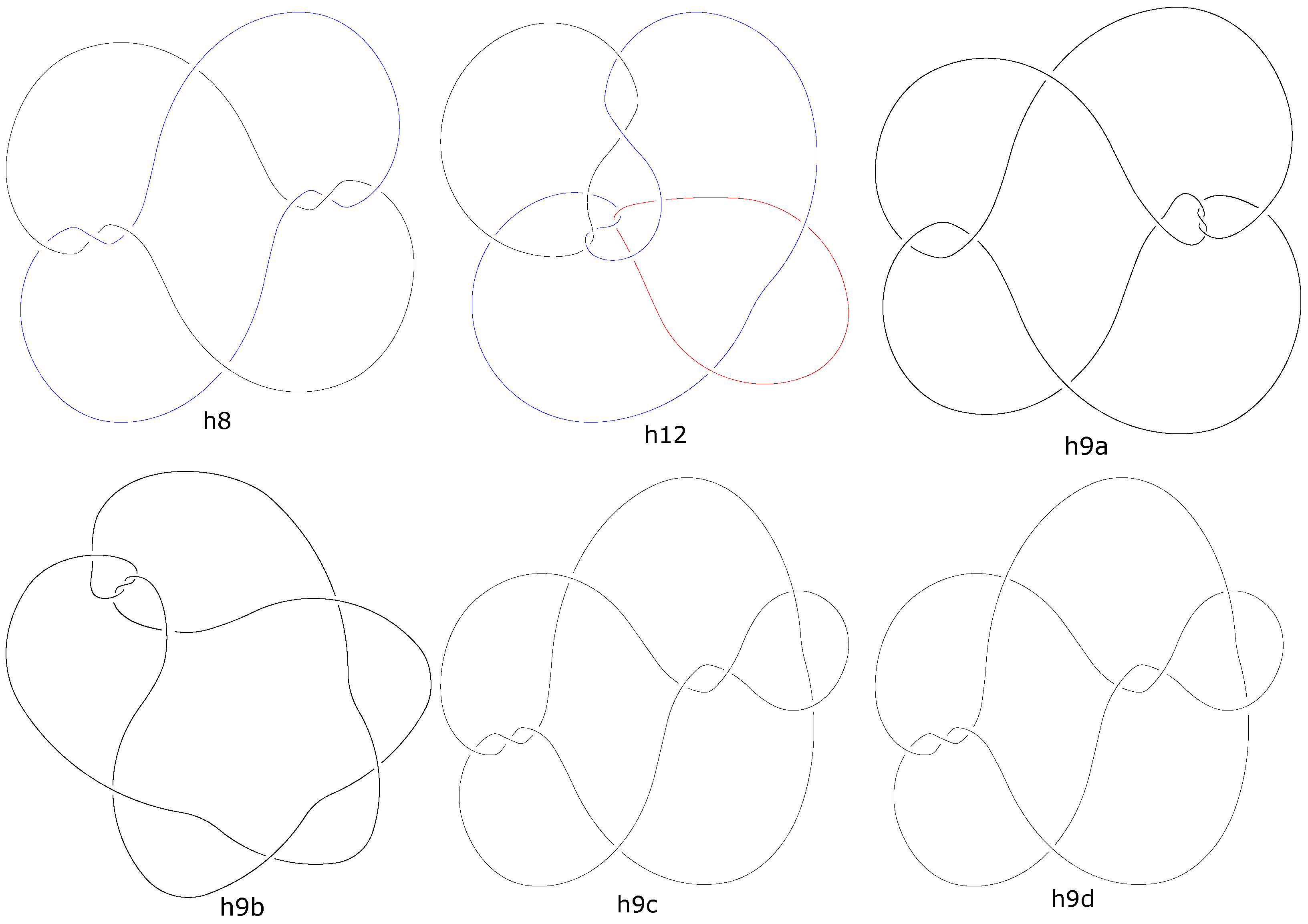
. Up to the mirror image, the only minimal rigid hard prime classical unlink diagram with two components is , and the only minimal rigid hard prime classical unlink diagram with three components is (see Figure 2). Furthermore, the only minimal rigid hard prime classical unknot diagrams are the four diagrams , shown also in Figure 2. From the computational checking of all spherical diagrams up to several crossings, we conclude the following:
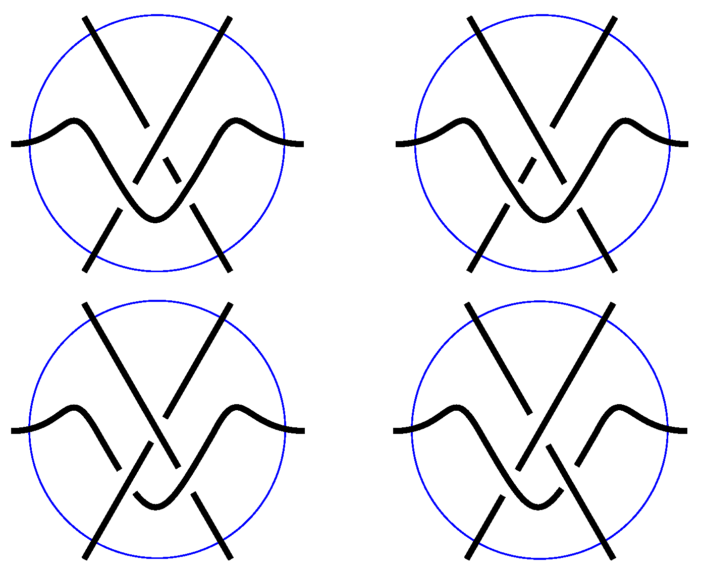
Lemma 1. The diagram shown in Figure 3 is a minimal unknot diagram such that all regions with the opportunity to make move or -type move share exactly one edge (shown in dashed line). In
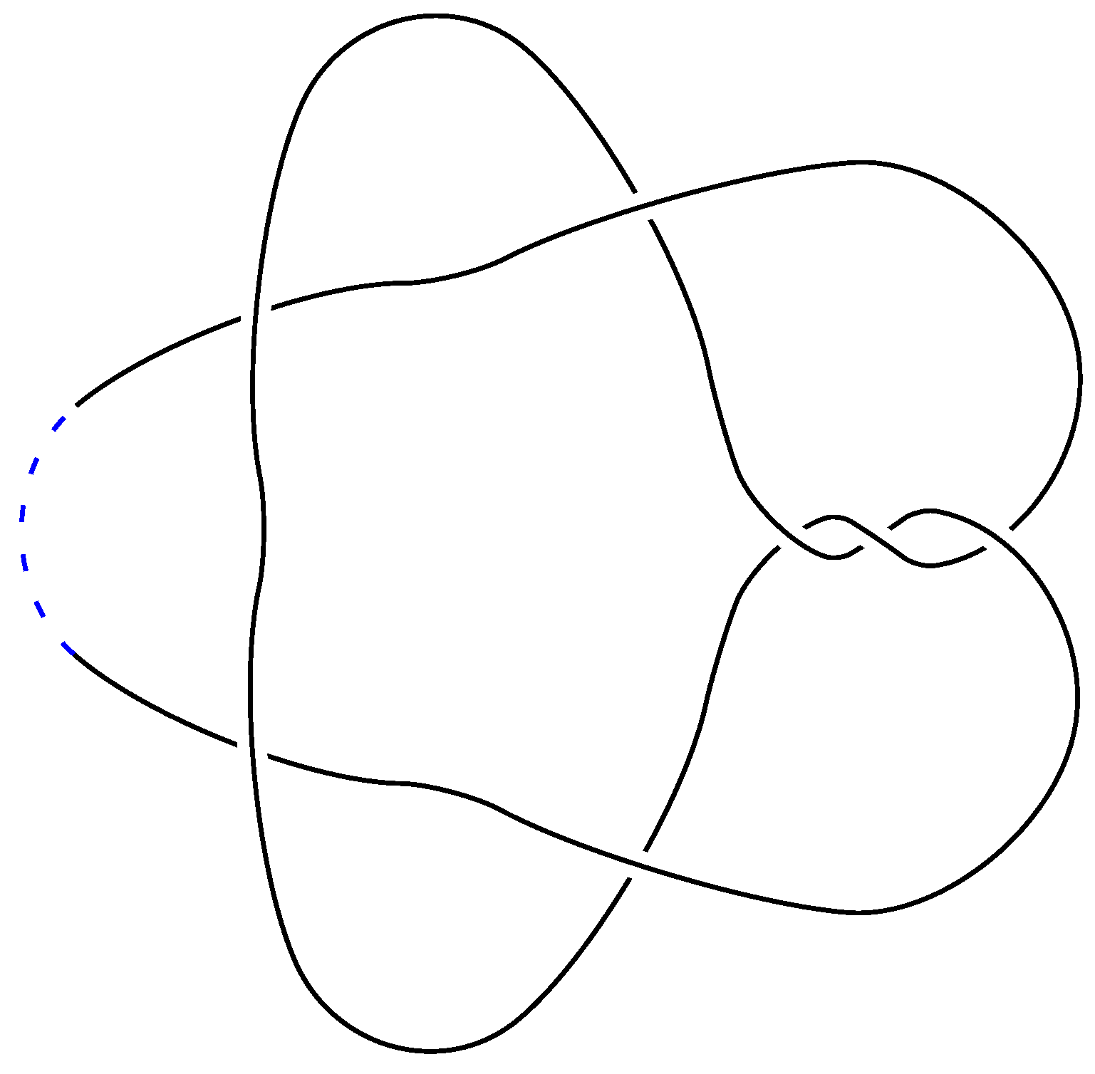
Figure 4, we have all types of local neighborhoods of a triangular region in a link diagram. We have exactly two cases (in the first row) where a triangular region has the opportunity to make the
-type move, call it
-triangle.
For any link, define as the minimal number of in D, among all minimal diagrams (i.e., diagrams with crossings) D for L. In case there is some minimal diagram for L without any , we put . We shall now state the following theorem:
Theorem 2. Any link L has a diagram D that is a rigid hard diagram. Moreover, we can choose D, such that we have the following:for any non-split non-trivial link L. Proof. For a case where the link L is trivial, we can take diagrams from Theorem 1 and their proper amount of connected sums to obtain a rigid hard diagram with the desired number of components. Assume, from now on, that L is non-trivial. If it is a split link, then we can obtain the following procedure for every sub-diagram component: obtaining a rigid hard diagram as a disjoint union of rigid hard diagrams of non-split components. Therefore, we assume that we have a minimal diagram for L, which is a connected diagram and has at least two crossings.
Consider D as a connected sum of a minimal diagram for L with the diagram along the dashed line inside every triangular region of where there is an opportunity to make an -type move, with the edge used in the sum edge being one of the edges bounding the triangular region. If there is no such region, we make only one connected sum with the arbitrary edge of , and the inequality is obtained. From now on, let us assume that there is at least one triangular region with the opportunity to make the -type move, call it -triangle. Then, we obtain no new region having fewer than 4 edges in the boundary, so the diagram of the sum is a rigid hard diagram.
The diagram
has 7 crossings; therefore, in
D we have
crossings in
D. □
We can derive the following general upper bound without knowledge of the number of .
Theorem 3. We can choose D, such that we havefor any non-split non-trivial link L. Proof. Let be a minimal diagram for L, considered here also as a 4-valent graph, having crossings.
By the Euler characteristic formula for spherical 4-valent graphs (here connected projections of the links), the number of all regions in
is
, and the number of edges in
. Let us consider only triangular regions in the graph
G being a connected shadow for
. We glue together any two such triangles to form a quadrilateral, and then we proceed to any other possible pairs, etc., and we end with only triangles isolated from each other. Call the set of such isolated triangles by
S, and the set of constructed quadrilaterals by
Q. We can now apply Theorem 2 for only
in
S and for one
for each quadrilateral in
Q making the connected sum in an edge used to glue our quadrilateral from two triangles, preventing both of them to be
. At least one (the diagonal) edge in each element of
Q is not the edge of any element of
S, and we have a total of
in a graph in
G; therefore,
. We also know that each element in
Q covers two faces of the starting graph
G with
faces, so
. We can now count and bind the number of required connected sum operations
as follows:
The number
is an integer, so we obtain
. Each connected sum adds exactly seven crossings, so
□
We see that, in the proof of the previous proposition, the construction leads us to generally not prime diagram. It is natural then to search for possibly prime rigid hard diagrams for a given knot or link with fewer crossings.
In
Figure 5, an example is shown of a minimal rigid hard diagram of the trefoil knot. Notice that it is a prime diagram, and it has nine crossings, while the minimal diagram of the trefoil has three crossings.
The rigid hard index of a link L, denoted by , is the difference between the number of crossings in a minimal (with respect to the number of crossings) rigid hard diagram for L and the crossing number of L.
From the previous examples of prime minimal rigid hard diagrams of trivial links (that are denoted
, where
n is the number of its components), we can conclude directly that
From Theorem 2, particularly for any alternating link or generally for links not having any
triangle in a minimal diagram non-trivial non-split links
L, we have
We also directly know that, for any non-split non-trivial link
L, we have
We computationally generate (by checking all diagrams) the rigid hard index of prime knots and links, which is shown in
Table 1. The table consists of prime knots and links with the crossing number being less than nine.
The letters K and L in the name stand for Knot and Link, respectively, the number after that letter is the crossing number, the letters a and n stand for an alternating and nonalternating, and the number after that stands for the index of a given knot or link in the tables of knots or links with the same crossing number. We consider links and their names up to the mirror image because the rigid hard index of a given link and the rigid hard index of its mirror image are the same.
4. Shaky Hard Diagram
From
Section 1, we know that any hard diagram of any link must be a non-alternating diagram. In the case of shaky hard diagrams, it can be deduced directly because the opportunity to make the Reidemeister III move requires that at least one strand involved in the move has two crossings that do not alternate.
Theorem 4. There exists a shaky hard diagram of the unknot and unlink of many arbitrary components.
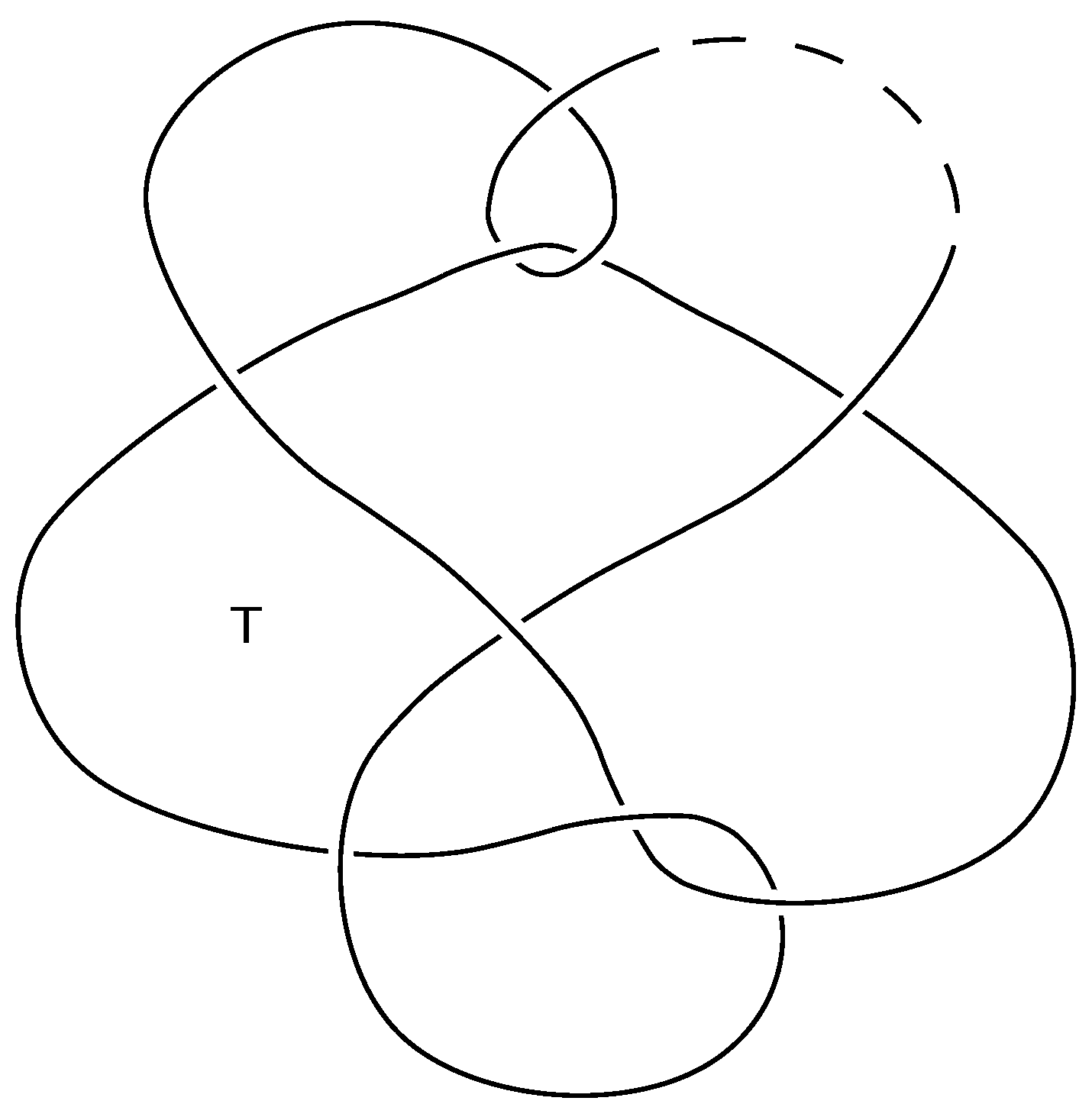
Proof. In
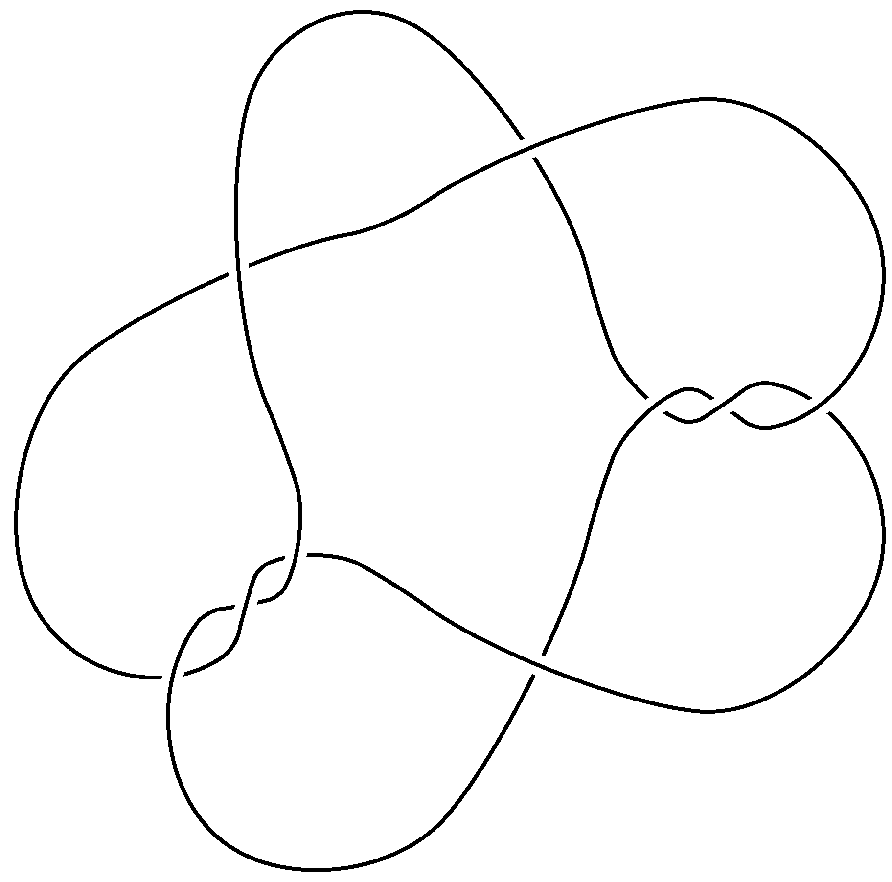
Figure 6 is shown an example of a prime shaky hard diagram of the unknot (it has 10 crossings so one can test the triviality by calculating its Jones polynomial). The case of two-component unlink examples are shown in
Figure 7 (notice that those diagrams of unlinks differ by crossing changes at two crossings).
They are all shaky diagrams because each has a triangular region, marked by the letter T that has the opportunity to make the -type move. They are also hard because each diagram has exactly one such triangular region, and after performing the -type move, it can be easily checked that the resulting diagrams have also exactly one triangular region, which has the opportunity to make the -type move and no opportunity to make the or move. Therefore, to try to reduce it further without increasing the number of crossings one has the potential move to make on that one triangular region, resulting in returning to the original started diagram.
For the shaky hard diagram of the unlink of arbitrary many components, it is sufficient to take a diagram from
Figure 6 and make connected sums with sufficient copies of the diagram
from
Figure 2, with the connection arc being far from (i.e., not touching) the region
T and its neighbor regions.
□
By a similar construction as in Theorem 2, but instead of one diagram
, we take the connected sum with the diagram
shown in
Figure 8 (along the dashed line), we obtain the following:
Proposition 2. Any link L has a diagram D that is a shaky hard diagram. Moreover, we can choose D, such that we havefor any non-split non-trivial link L. Proof. Let
be a minimal diagram of
L with
crossings and with
triangular
-regions. The construction follows Theorem 2, except that we use one copy of the diagram
(see
Figure 8), and, for the remaining
-triangles (if any), we use the diagram
(
Figure 3).
Each inserted removes the local -opportunity while adding 7 crossings (as in Theorem 2). A single inserted contributes 9 crossings and creates exactly one persistent -triangle, ensuring the final diagram is shaky (there remains a place to perform an -move).
Choose one
-triangle of
and insert
there; at the remaining
-triangles (if any), insert
. The total increase in crossings is therefore
If has no -triangle (so ), we insert one along an arbitrary edge, which again yields . In either case, the resulting diagram is hard (no or applies) and shaky (there is a remaining -move), proving the proposition. □

