Abstract
This paper presents the development, modeling, and validation of a scaled UAV-VTOL low-cost prototype equipped with a jet propulsion system with vertical take-off and landing capabilities. The prototype is designed as an experimental testbed for reusable rocket control strategies, with a particular focus on thrust vectoring and landing stabilization. The study begins with the evolution of the CAD, followed by a guide for the correct assembly of the device. The development of the electronic system included the integration of an ARM Cortex-M7 microcontroller, inertial sensors, and a LIDAR-based altitude measurement system; this was enhanced by a Kalman estimator to mitigate the sensor’s noise. A series of experimental tests were conducted to characterize the key subsystems. Actuator characterization improved the linearized nozzle control model, ensuring predictable thrust redirection. The test bench results confirmed the EDF’s thrust curve and its ability to sustain controlled flight, despite minor losses due to battery discharge variations. Furthermore, state-space modeling aided the development of controllers for altitude stabilization and attitude control, with simulations proving the feasibility of maintaining stable flight conditions. Experimental validation confirmed that the prototype provides a practical platform for future research in reusable rocket dynamics and autonomous landing algorithms.
1. Introduction
The development of aerospace engineering and space exploration has always been related to the design and construction of gigantic aircraft and rockets; this has always involved huge economic and environmental expenses. A 2018 report by Bryce Space and Technology [1] reported that the aerospace industry generated approximately USD 366 billion in revenue. This is without considering the high costs of maintenance, development, fuel, and losses caused by accidents in orbit or launch. Therefore, there is a constant interest in reducing costs by improving vehicle performance, developing more precise and efficient control systems, and experimenting with scaled prototypes. As an example, ref. [2] proposed the development of a guidance, navigation, and control (GNC) system for a vertical take-off and landing rocket designed by a student team, aiming at improving accuracy, precision, and robustness during the landing phase. On the other hand, ref. [3] presented a scaled prototype based on similarity principles for the landing system of a reusable launcher in order to conduct impact tests, identification of potential extreme conditions, and evaluation of the dynamic response of the landing system under each scenario. The landing of spacecraft launch rockets has been one of the greatest advances in recent years; the reuse of these greatly reduces the costs of a space mission. However, the cost of designing, building, operating, and maintaining these vehicles remains high, at around USD 62 million per launch [4]. Due to the reasons mentioned, in Colombia, students who are interested in this industry do not have the possibility of practical entry into the design of control and optimization systems. Therefore, the development of small-scale prototypes of unmanned aerial vehicles (UAVs) with vertical take-off and landing (VTOL) capabilities, along with a jet propulsion system which largely emulates full-scale rockets, has proven useful. In ref. [5] and ref. [6], the construction and use of VTOL UAV prototypes are addressed with the purpose of testing and validating different control strategies for various flight phases. The main purpose for this is that UNAB students can test different control strategies for take-off, flight trajectories, and stabilization during the descent and landing of the vehicle. Autonomous landing is a crucial milestone in aerospace engineering [7], enabling safer and more cost-effective missions. In the literature, it is common to find tail-sitter VTOL UAVs, as seen in [8], consisting of four rotors that provide the necessary thrust and control for the vehicle. However, this configuration does not capture the control challenges required by a real rocket, as rockets typically rely on a single propulsion unit. As proposed in [9], using a configuration driven by a single electric ducted fan (EDF) offers a closer resemblance to a real rocket. Nevertheless, by employing deflectors to redirect the airflow, it still falls short of being a completely faithful alternative. The design presented in this paper uses a centrally mounted EDF coupled with a gimbaled nozzle with two degrees of freedom, allowing the prototype to control both altitude and orientation by manipulating the EDF’s thrust and the nozzle’s direction. By employing a fully electric engine, the prototype offers the advantage of not needing chemical propellants or jet engines; therefore, unlike a conventional rocket, it maintains a constant mass throughout the flight. Thanks to this, costs are lowered, and the control systems to be implemented are simplified. Furthermore, because it does not use flammable substances that require careful handling, the prototype is safer to build, operate, and maintain while also minimizing its environmental impact.
Colombia has also advanced in the aerospace sector by launching satellites into orbit and investing capital in this industry [10]. By 2018, approximately USD 156.7 million had been invested by public and private entities in Colombia. One of these satellites was Libertad 1, launched in 2007 as an academic milestone with sponsorship from Sergio Arboleda University. In 2018, the defense sector launched the FACSAT 1 Earth observation satellite, based on the CubeSat 3U platform, with a resolution of 30 m per pixel. More recently, its successor, FACSAT-2 “Chiribiquete”, was developed and launched in mid-April 2023. However, these efforts do not encompass the entirety of Colombia’s aerospace research and development. According to the CIGEPI (Center for Technological Information and Support for Industrial Property Management) database, the number of Colombian patents associated with the field of aerospace research is 355 as shown in ref. [11]. These patents were associated with a list of 22 words related to the aerospace and telecommunications sector. At the same time, a growing business sector has emerged: there are 52,862 business registrations linked to the aerospace industry. Yet only 172 are associated with ISIC code 2651, “Manufacture of measurement, test, navigation and control equipment”, out of a total of 203,360 registrations. A more detailed analysis is presented in [12]. Furthermore, a 2024 study from the Graduate School of the Colombian Air Force [13] combined quantitative and qualitative approaches to identify characteristics of hybrid rockets and explore opportunities for their implementation in Colombia. The study emphasized the importance of strengthening the country’s infrastructure to seize emerging opportunities and establish a solid presence in the global space market.
This article addresses the development of a prototype, beginning with its mathematical model and CAD, followed by the design of the thrust vectoring system and the implementation of the electronic subsystems. It also describes the parameterization of the device and the calibration of its sensors, a process that culminates in a functional prototype ready for the validation of control strategies.
2. Design
The initial considerations for the conception of the prototype focused on a simplified rocket design. Since the exact dimensions were not yet defined, this did not pose a major problem. The first draft of the CAD model was created as a basic rocket concept, designed to support itself structurally while maintaining an aerodynamic form.
Figure 1 reveals the first sketch of the prototype, which differs significantly from later versions. The design originally included retractable landing gear; however, this feature was later removed because it compromised the structural rigidity of the device and increased its weight, as well as the number of actuators, controllers, and circuits required. Another key feature considered was the inclusion of small fins at the top of the dome, highlighted in grey, which were intended to provide stability during free fall. These fins were passive, without actuators, and relied solely on wind resistance for activation. This first conceptual design proved excessively complex, diverging from the main goal of creating a simple platform for implementing and testing control algorithms.
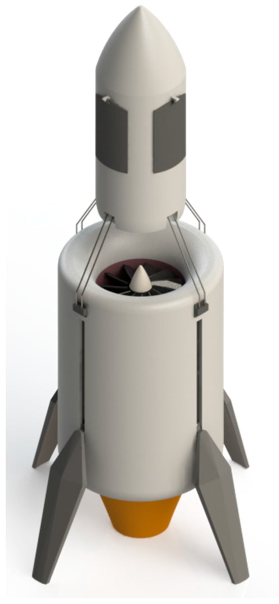
Figure 1.
First design approach of the prototype, prototype V1.
In the next CAD iteration, several key structural modifications were introduced. As depicted in Figure 2, the retractable landing gear was replaced with a rigid metal frame, improving the durability of the prototype. Each of the four legs was secured at three points on the chassis, with an additional support point at the dome’s top. This reinforcement enhanced the mechanical stability but also added considerable weight. At this stage, the overall mass of the batteries, EDF, and ESC and the precise dimensions of the electronic components had not yet been fully assessed.
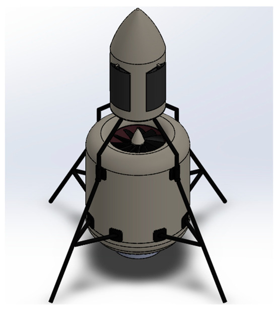
Figure 2.
Prototype V2: metal legs variation.
With the selection and acquisition of all critical components, a third refined model was created, retaining essential design elements such as rigid legs and a protective dome. In this version, the metal frame legs were replaced with 3D-printed ones for weight reduction. The dome was preserved to encapsulate the control systems, and a more robust structural framework ensured stability and integration of all components, as illustrated in Figure 3.
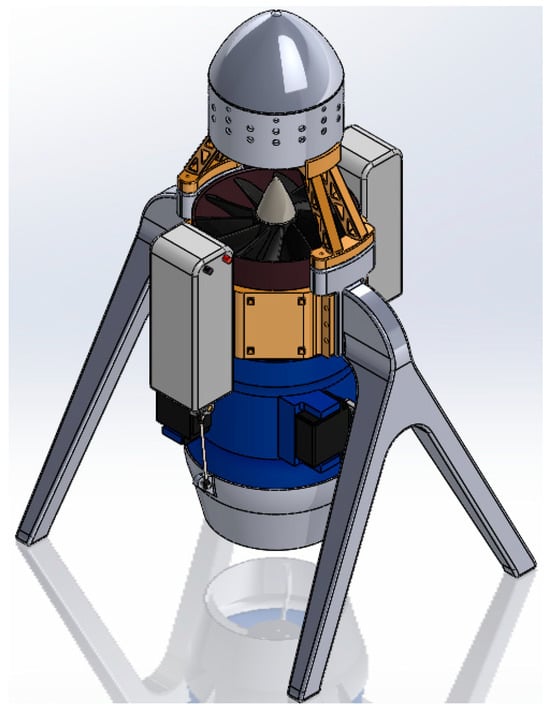
Figure 3.
Prototype V3: fully 3D-printed structure.
Further iterations focused on the nozzle subsystem, which underwent multiple redesigns involving additional moving parts. Discarded designs are shown below in Figure 4a,b.
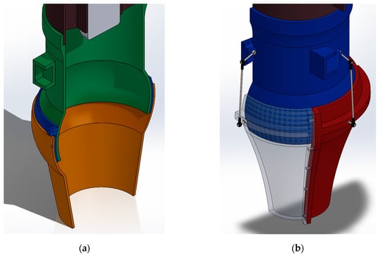
Figure 4.
Discarded nozzle designs: (a) 3-piece stack variation and (b) modular nozzle variation.
As shown in Figure 4, the first design (a) was expected to have a sufficient slip coefficient, allowing smooth movement with minimal friction loss. However, the incorporation of a Cardan joint to connect the moving parts and facilitate motion was not initially considered. After testing, this design was ultimately discarded. In Design A, the nozzle consisted of one fixed piece and two independently moving pieces, while in Design B, a more compact configuration was introduced, with two main components forming a three-part nozzle assembly. The duct, represented by the green (a) and blue (b) components that connect the nozzle to the EDF, remained unchanged in both designs until the final transition.
Challenges related to friction and tolerance, particularly due to the surface roughness of 3D-printed components, highlighted the need for an additional linkage system for the nozzle. Consequently, the duct was structurally modified, transforming it from a simple hollow tube into a reinforced internal structure, as depicted below. In this improved design, the newly integrated support framework was directly connected to the nozzle, thereby enhancing overall stability and functionality.
The nozzle redesign incorporated a gimbal joint system (Figure 5a) to improve motion transmission while reducing friction losses. Additional modifications were made to both the length and the amplitude of the nozzle output (Figure 5b). Further redesigns became necessary when it was observed that the EDF lacked sufficient rigidity to withstand impacts. To address this limitation, a structural component was developed to support the system’s power elements and sensors. This component, referred to as the “rib” or battery support, significantly improves overall rigidity and durability.
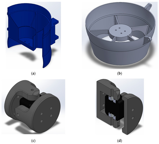
Figure 5.
Nozzle system internal parts: duct section view (a), nuzzle isometric view (b), gimbal (c), gimbal section view (d).
The chassis of the device is mounted around the EDF-embedded handles, which provide structural rigidity and facilitate mounting other elements. Each of the four legs is secured with two anchor points, ensuring uniform weight distribution on flat surfaces and sufficient clearance for air displacement during take-off. Figure 6c shows how the legs are mounted directly to the EDF chassis in a sandwich-like configuration. Maintaining symmetry was identified as a critical design principle, since any asymmetry could cause deviations during vertical take-off, complicating control efforts.
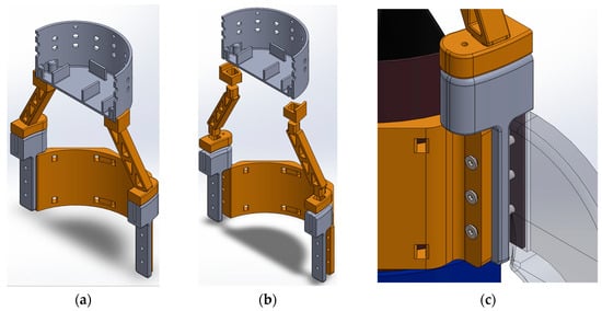
Figure 6.
Dome assembly (a), 10-piece exploded view (b), and closeup of structural linking to EDF-embedded handles (c).
2.1. General Features of the Built Prototype
Figure 7 presents a general view of the assembled prototype. The EDF (highlighted brown) serves as the central propulsion unit. Attached to it are two orange-colored ribs, which reinforce structural rigidity and serve as coupling points for the landing gear (gray fork-shaped side pieces) and the batteries. The prototype uses two 6-cell LiPo batteries in series (cyan), for a total of 12 cells with a rated voltage of 44.4 V. The EDF speed controller is highlighted in gold. Above the EDF, a cylindrical compartment topped with a conical dome houses the control electronics, including the flight computer, IMU, LIDAR sensor, and auxiliary components. From this description, it is inferred that the EDF serves as the centerpiece of the design, with all subsequent adaptations revolving around this component. Coupled directly below the EDF is the nozzle subsystem, comprising three main parts as shown in Figure 8.
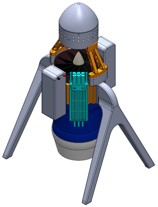
Figure 7.
General assembly CAD model showing fully mounted components (Source: own).
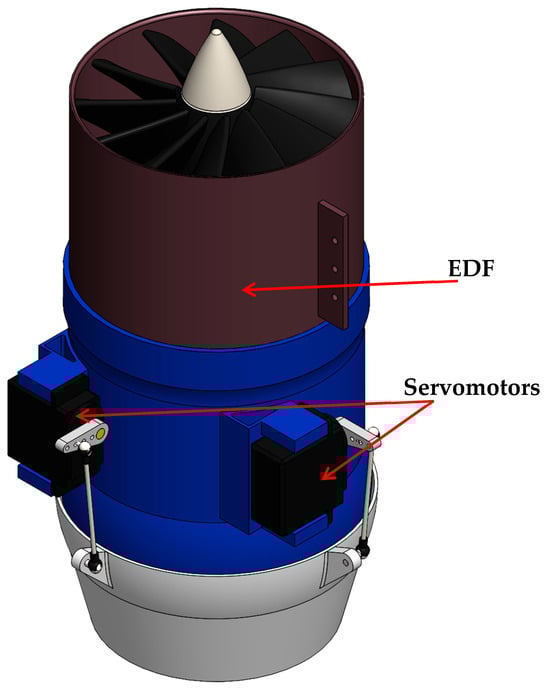
Figure 8.
Closeup of general placement of EDF, actuators, and nozzle subsystem.
The “duct” (blue piece) supports the servomotors that actuate the nozzle. It connects directly to the bottom of the EDF, positioning the servos 90° apart on the horizontal plane to provide the two degrees of freedom required by the nozzle. The nozzle (grey piece at the bottom) redirects the airflow generated by the EDF through a crank–rocker linkage mechanism.
A Cardan joint (Figure 9) links the duct and the nozzle, enabling the two degrees of freedom required for thrust vectoring. This subsystem was a critical innovation for enabling altitude and attitude control.
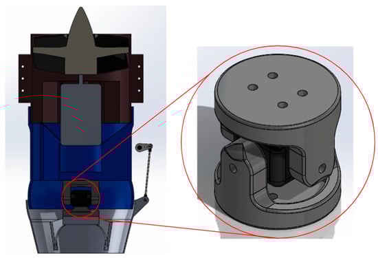
Figure 9.
Cardan joint closeup highlighted with a big red circle, and model location highlighted with a small red circle.
2.2. Identifying the Geometric Model of the Nozzle
The mathematical models used to develop the control system are based on the model presented in [13], which applies the Newton–Euler method [14], as well as on the model in [15], which incorporates the coupled EDF dynamics into the overall model. In contrast, the mathematical model presented here focuses exclusively on the dynamics of the reroutable nozzle.
The angles and represent the nozzle rotations, which are controlled by two servomotors through a four-link mechanism ending in a rocker link.
Figure 10 illustrates the vectors defined between the VTOL’s center of mass and the points of interest present in the mechanism. Through vector analysis, the nozzle angle can be obtained as a function of the corresponding servomotor angle.
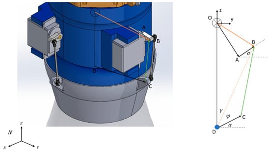
Figure 10.
Nozzle system mechanism vectors diagram (Source: own).
By simultaneously solving the system of equations describing the four-bar mechanism, it is possible to express the angle as a function of :
As the values of σ are varied, the corresponding values obtained for are graphed, as shown in Figure 11. To simplify the analysis of this behavior, the graph was linearized within the operating range of the servomotor, between −60° and 60° for σ. For the device developed, the resulting equation describing the linearized relationship between σ and α is shown in Figure 12. The terms used in this equation are explained in Appendix A.
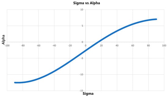
Figure 11.
Nozzle angle with respect to the servomotor angle (Source: own).
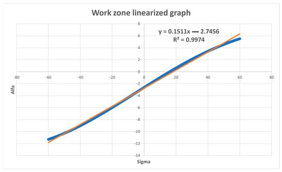
Figure 12.
Linearized work area, linear in orange and blue graphed data (Source: own).
2.3. Design Overview
Table 1 lists the materials and components used in the construction of the device, corresponding to the electronic subsystem of the prototype. In addition, a PLA filament was employed for 3D printing of the entire structural assembly. The quantity of material used—and consequently the overall cost—depends on the specific printing configurations selected during fabrication.

Table 1.
Bill of materials.
3. Build Instructions
The prototype components were primarily fabricated using 3D printing. At its core, a 120 mm Changesun-brand EDF served as the primary propulsion unit and central structural element. The CAD model was designed using the EDF’s exact dimensions, complemented by reference drawings from the manufacturer’s website.
Assembling the prototype is a straightforward process. It begins with the dome section, which consists of approximately twelve individual components. These parts are color-coded: extension pieces are in orange, and the dome and EDF link pieces are in grey, as shown in Figure 13.
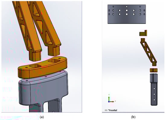
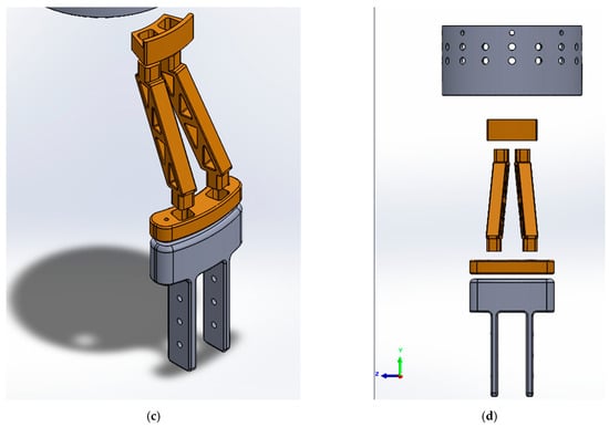
Figure 13.
Prototype upper section assembly: bracket union closeup (a), frontal view of assembly (b), isometric view (c), left side view (d).
In the central section, the orange and grey pieces include holes designed to hold a 2.2 mm metal bar, ensuring alignment and structural fixation. These bars can be inserted easily, providing proper positioning of the parts. The dome components are joined using epoxy resin, superglue, or any specialized solvent capable of briefly softening the plastic to achieve a strong bond. This procedure must be applied symmetrically on both sides of the device. Possible improvements to this upper section may include integrating quick-release mechanisms in the assembly links, adding cable management guides to reduce loose wiring, and further reducing weight.
Once the dome section is assembled, the middle section must be carefully secured (Figure 14). Both sides should be fastened simultaneously, or one side should be fully fixed before proceeding with the other. The assembly sequence is as follows: the EDF (blue) is attached to the leg (purple) by aligning the guide holes. Next, the dome support piece (yellow) is positioned. The structure resembles a sandwich assembly, with the EDF at the center, followed by the leg, the dome support, and finally the ribs (orange) attached on both sides, which must be attached simultaneously. Once all components are in place, an M3 screw of at least 45 mm is inserted through the upper and lower guide holes; the middle guide is secured only after both sides are fully fastened.
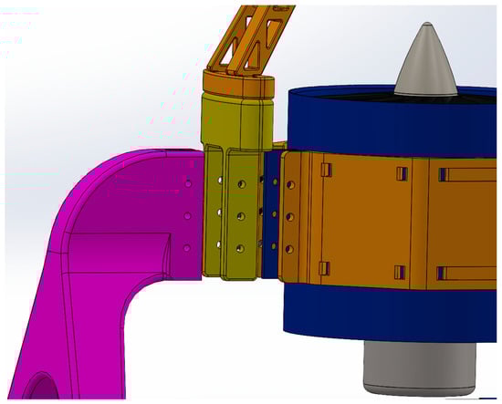
Figure 14.
Midsection assembly, showing piece differentiation by colors and general placement.
With the upper and middle sections completed, assembly continues with the installation of the Cardan joint, a critical part responsible for transmitting motion to the nozzle. The joint consists of a central hub (black) with guide holes for securing bearings. Each arm (grey) of the joint has a groove designed to accommodate a 3.5 mm diameter rod, ensuring a precise fit with the bearing shaft. The geometry of these elements prevents misalignment unless manually altered.
The gimbal joint is assembled through a simple but precise sequence. First, the fixing screws are inserted into their respective holes. Next, the bearings are carefully placed into the guide grooves of the central hub. Once positioned, one of the arms is aligned with the bearing’s internal hole to ensure a secure fit. A clamping rod, 3.5 mm in diameter and 15 mm in length, is then inserted, leaving a slight protrusion to allow future adjustments if required. Given its role in motion transmission, the gimbal joint must form a reliable connection with both the preceding and subsequent links in the assembly. For this reason, screws are positioned with their heads inside the joint to improve alignment and stability. Potential improvements to this gimbal design include embedding nut inserts in the gimbal’s arms, reducing the weight, and incorporating a release mechanism to facilitate access to the internal components.
It is recommended not to machine the gimbal joint faces after the necessary internal adjustments have been completed. The images provide an overview of the internal configuration but do not serve as a detailed assembly guide. Given the precision required, assembling these parts demands dexterity and the use of small calipers to ensure a high-torque adjustment. After assembling the gimbal joint as shown in Figure 15, the recommended sequence is to first construct the duct with the gimbal, then attach the second half of the gimbal to the nozzle, and finally install the servomotors with their linkage rods to complete the subsystem before mounting the EDF on top. Figure 16 is provided solely to illustrate the internal configuration of the fully assembled nozzle subsystem.
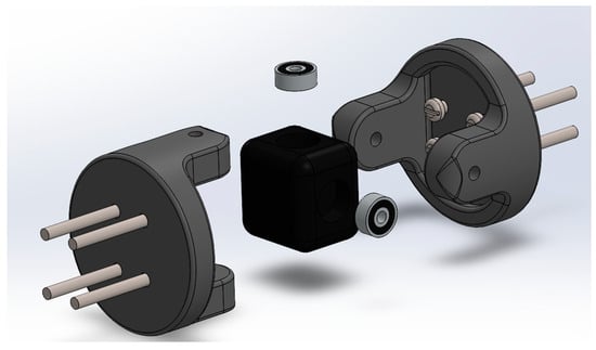
Figure 15.
Gimbal mechanism joint assembly model, exploded view.
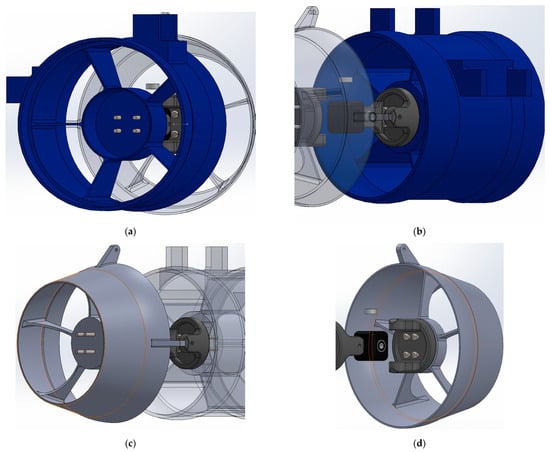
Figure 16.
Duct, nozzle joint, and gimbal joint: top view of transparent nuzzle (a), left-side view of transparent nuzzle (b), left-side view of transparent duct (c), gimbal face and nuzzle interaction (d).
As shown in Figure 17, the actuators responsible for adjusting the nozzle’s orientation are assembled in their designated positions. At both ends of the connector bar (Figure 17a), spherical joints are incorporated to enhance flexibility and mobility, allowing smoother movement. These joints are secured with M2 screws, firmly fastening them to both the nozzle and the servomotor arm (Figure 17b). The servomotor (Figure 17c) is bonded to the blue duct either by epoxy resin or by screws inserted into the support arms built into the duct, ensuring a stable connection. Furthermore, the minimal tolerances in the assembly create an optimal balance between friction and rigidity, improving the system’s overall resistance to vibration.
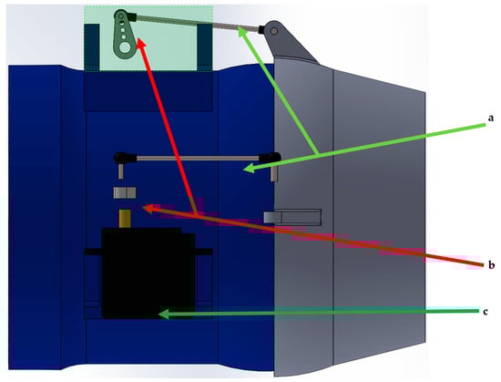
Figure 17.
Exploded view of servo placement and general link mechanism with highlighted parts.
3.1. Electronic PCB and Implementations
The electronic system is divided into three main sections, as shown in Figure 18. The first section contains the power electronics, which include the battery circuit, speed controller, and EDF connection pins (highlighted in yellow). The second section houses the control unit, which functions as the brain of the device. This consists of an ARM Cortex-M7 microcontroller operating at 600 MHz (see [16] for details), highlighted in red. The third section is dedicated to sensors (highlighted in blue). It integrates the following: an IMU sensor (BNO055 inertial measurement unit), a LIDAR sensor with pin connectors for altitude measurement with high accuracy at altitudes less than 5 m, and a barometric sensor for measuring altitudes above 5 m. Additionally, a power separation stage is included to prevent overvoltage and eddy current interference between the power and control subsystems. The developed PCB has an RGB LED and a buzzer, which provide visual and audio signals for the operational status of the device. The PCB design files, together with additional 3D models, will be made available as Supplementary Materials.
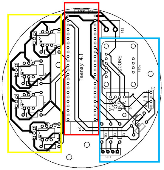
Figure 18.
Control PCB layout, with labeled components (Source: own).
3.2. EDF Net Thrust Testing Bench
To obtain the EDF operating curve, a dedicated test bench was constructed, as shown in Figure 19. Different PWM values were applied, and the corresponding thrust values were measured. Once collected, the data were interpolated in the operating curve shown in Figure 20, where the red line represents interpolated data and the blue line represents raw data.
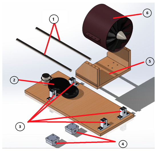
Figure 19.
CAD model of the thrust test bench, exploded view, with labeled parts (Source: own).
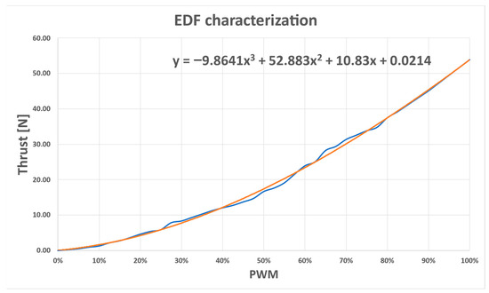
Figure 20.
Thrust curve vs applied PWM, at a sustained voltage of 44 V (Source: own).
The test bench consisted of an EDF support structure (5) mounted on two 8 mm steel shaft rails (1), using two linear bearings (4) to enable guided movement. The EDF (6) is attached to the EDF support structure by means of screws. The shaft rails were fixed to a wooden base using supports (3), restricting the EDF’s movement to a single direction. A hitch screw was added to connect the EDF support structure to a dynamometer (2), which measured the thrust force produced.
For these tests, stable power conditions were maintained. The batteries were kept at a constant voltage for each trial. Specifically, PWM inputs were varied at intervals of 25 ms, ranging from 1000 to 2000 ms, for a total of 41 tests conducted at an average voltage of 44 V.
From these measurements, the EDF operating curve was obtained, establishing the relationship between thrust output and PWM input at constant voltage.
Based on this operating curve, a nonlinear equation was derived to describe the EDF’s performance. For implementation within a control strategy, this equation was linearized, as shown in Figure 21, where the red line represents interpolated data and the blue line represents raw measurements. Since the thrust generated by the EDF exceeds the weight of the device at approximately 75% PWM, a linear equation was formulated using the thrust data in the 60–100% range. This interval was selected as the EDF control range required for sustained flight.
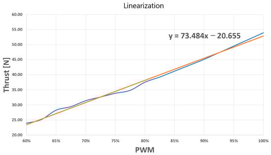
Figure 21.
Linearized equation from 60% PMW onwards (Source: own).
3.3. Estimated Overall Power
The maximum output power specified by the EDF manufacturer is approximately 6.78 kW. This value can be estimated by multiplying the theorical maximum sustained current of the motor by the maximum applied voltage. For this model, the motor supports a maximum voltage of 45.2 V and a sustained current of 150 A. However, during the tests at maximum thrust, the system demonstrated a peak power consumption of approximately 6147.2 W. At that point, the applied voltage was 45.2 V and the measured instantaneous current reached 136 A, before declining due to battery discharge. Based on these measurements, the overall efficiency of the system can be calculated as the ratio of experimental power to theoretical power, yielding a value close to 91%. Nonetheless, this efficiency decreases gradually as the batteries discharge. After the peak current of 136 A, a more stable current in the range of 125–123 A was observed for a relatively short duration of up to about 2 min.
4. Operating Instructions
Upon completing the assembly process, the main power sources must be connected before beginning the test phase. A general warning should be emphasized: high-power batteries pose significant risks if handled improperly. Users must check battery polarity before connection, always connect the positive terminal first, and remain aware of the possibility of short circuits. Due to the high discharge capacity of the batteries, peak currents can cause severe burns or even explosions if mishandled. Therefore, manufacturer usage guidelines must be followed carefully, and appropriate safety equipment—such as protective glasses and gloves—should always be worn.
After following all safety measures and connecting the equipment, users may configure the device according to their specific requirements. Configuration may vary depending on the system architecture or application, particularly regarding the power supply for the propulsion and control subsystems.
The sensors and actuators must be correctly connected to the control printed circuit board (PCB) and to the EDF speed controller (ESC).
The embedded control system provides five physical input/output interfaces, which are used to integrate the necessary components: two servomotors, the EDF, a status LED indicator, an inertial measurement unit (IMU), and a LIDAR sensor. Connections must be made carefully, ensuring that high-power and low-power peripherals are connected to the correct ports, as specified in Figure 16.
Once hardware integration is completed, the microcontroller must be programmed according to mission-specific requirements. In this study, the system was configured for validating vertical take-off and landing control algorithms. Nonetheless, the prototype architecture also supports additional functionalities, such as fine horizontal positioning control, hover stabilization, and vertical surveillance operations.
After programming and system interconnection, testing and calibration procedures are required. For testing, a routine program is recommended to perform preliminary checks on all peripherals before initiating flight tests. Typically, a 20 s delay is programmed to allow time for aborting the test if an issue is detected. This routine includes actuating the nozzle via servomotors, running the EDF briefly at low PWM, and activating the buzzer if LIDAR and IMU are registering data within normal ranges. If any component fails during this process, the test must be halted and the individual part inspected before proceeding. Additional issues and their solutions are discussed in the validation section.
Calibration is essential because sensors are not perfect and typically exhibit input noise that must be corrected prior to testing. For instance, after calibration, a systematic deviation was detected in the LIDAR sensor’s data acquisition process. To mitigate this issue, a Kalman estimator was integrated into the processing pipeline, as described in the following subsection.
4.1. LIDAR Sensor Calibration
The blue curve in Figure 22 shows the raw data obtained from the Luna-TF LIDAR sensor, which has a maximum measurement range of 8 m. As observed, the raw data present significant losses. This issue was partially resolved by increasing the sensor’s sampling rate, which reduced the intervals of missing data. In addition, a memory state was implemented: when data were lost, the previous measurement value was retained. The results of this solution are represented by the red curve in Figure 22. However, noise in the measurement was still evident. To address this, a Kalman estimator was implemented, producing the yellow curve in Figure 22, where measurements errors were effectively eliminated.
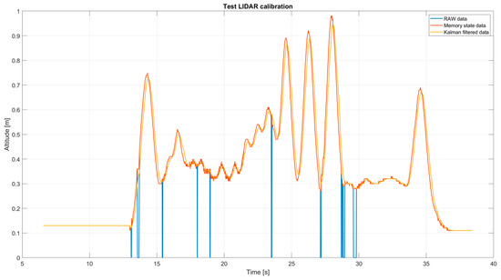
Figure 22.
LIDAR sensor calibration test results (Source: own).
4.2. Initial Setup and Calibration Checklist
Before flight, the following steps must be completed:
- Ensure that all mechanical parts (arms, propellers, landing gear, joints) are securely fastened.
- Verify that all power and data connections are correctly in place.
- Fully charge batteries and inspect them for swelling or damage.
- Power on the flight controller and confirm that the LED indicators display the correct status.
- Calibrate the inertial measurement unit (IMU) and magnetometer using the ground station software.
- Perform a range test of the radio link and telemetry system.
- Validate that the control system receives and executes commands correctly (e.g., arming/disarming, throttle input).
4.3. Basic Safety Precautions
The basic safety precautions are as follows:
- Always wear eye protection and avoid loose clothing when near moving propellers.
- Keep a safe distance (at least 2 m) during arming and take-off.
- Never operate indoors or in confined areas without safety netting.
- Use a fireproof container when charging LiPo batteries.
- Disconnect the battery immediately after landing to prevent short circuits or overheating.
- Ensure high-current connectors (e.g., XT60) are securely mated before flight.
4.4. Troubleshooting Tips
Even after proper assembly and setup, issues may arise during testing. Table 2 summarizes common problems, their likely causes, and suggested solutions.
Table 2.
Troubleshooting guide.
5. Validation
5.1. Model in State Space
To design the state-space control system, the classic form is used:
where the matrices A, B, C, and D are called the state matrix, input matrix, output matrix, and direct transition matrix, respectively. A vector notation is used for the matrices of states, inputs, and outputs, where x = [X1⋯Xn]T; u = [U1 ⋯Un]T; y = [Y1⋯Yn]T.
States:
Inputs:
Outputs:
Once the state-space representation of the system has been developed, it is possible to satisfactorily identify a series of oversimplified transfer functions.
Figure 23 shows, as a result, three transfer functions in the frequency domain: Gs(1,1), whose input is the percentage of PWM and whose output is the altitude in meters; Gs(6,2), whose input is the angle α and whose output is the angle ϕ; and Gs(5,3), whose input is the angle and whose output is the angle β.
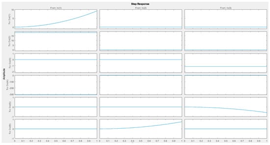
Figure 23.
Transfer functions relating to entries and outputs (Source: own).
Once the functions mentioned above are found, they are discretized with a sampling period of 6 ms, which is the minimum time it takes the embedded system to perform a control cycle. After performing the above-mentioned discretization, the following transfer functions are obtained:
The model is then validated by simulating the response of the nonlinear model using the discretized transfer functions, with zero inputs to the system.
Starting from the zero-equilibrium point, the outputs of the angular position remain at zero while the altitude decreases due to gravitational acceleration (Figure 24). Due to the absence of a thrust force, this scenario is understood as a free fall. These results are subtracted from Figure 25 and Figure 26, which have the simulation strategies programmed from Simulink.
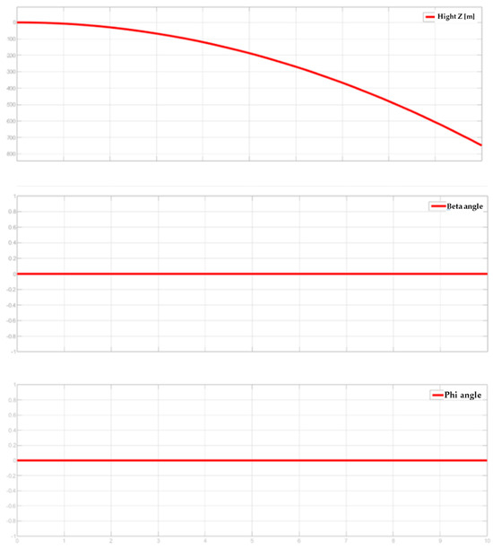
Figure 24.
Output in the face of a zero-system input, nonlinear system (Source: own).
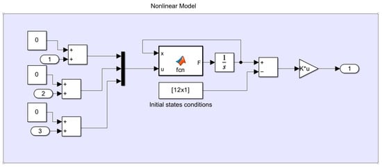
Figure 25.
Nonlinear model in Simulink subsystem internal block (Source: own).
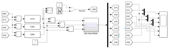
Figure 26.
Simulation model in Simulink (Source: own).
Using tuning techniques, suitable controllers were found that did not generate interference with each other to generate controlled outputs of the system, as shown in Figure 27.
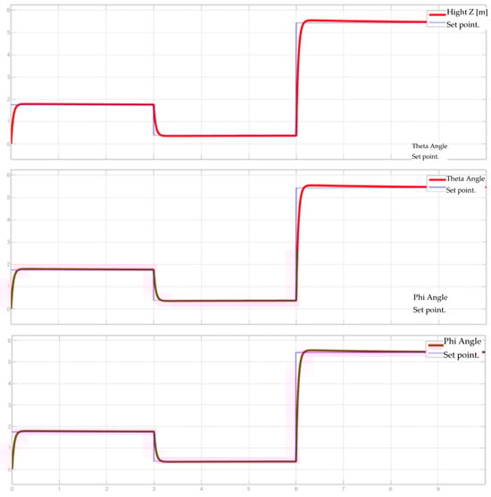
Figure 27.
Model output at multiple inputs (Source: own).
5.2. Limitations, Scope, and Non-Standard Events
Common issues may arise while configuring and testing the electronics. For example, actuators, sensors, or other peripherals may fail to operate as intended. To resolve such issues, components should first be tested individually, ideally using different control boards and power supplies to rule out damage. It is then recommended to check the test bench’s PCB for disconnected ports or damages. If both the PCB and component function correctly, library incompatibilities in the control code should be examined, as some libraries can generate processor-level conflicts.
Other common issues may arise during testing. For example, the device may successfully execute a take-off and landing but the SD card on board may fail to record the test results. This problem can stem from programming errors, data corruption, or hardware damage. To mitigate such risks, it is advisable to have at least one additional controller programmed for verification purposes, as well as have the SD card separately in order to rule out potential hardware failures.
Midflight issues can also arise, particularly those related to power or environmental interaction. For instance, batteries may deplete faster than expected, which may be the result of excessive discharge or the battery not being fully charged before take-off. In such cases, EDF testing must be performed to verify discharge currents and ensure power cables are of appropriate gauge. For the battery not being fully charged, a test protocol must be established involving a safety check of the battery’s charge level reading before conducting test flights. Other risks include interactions with wildlife; for example, insects or small birds may be drawn into the EDF during outdoor tests. To mitigate this, a protective mesh between the dome and EDF intake is recommended.
The device is best operated in controlled environments, such as indoor facilities with tall ceilings. While the modular design permits users to attempt advanced maneuvers, physical limits should not be exceeded. For example, the legs cannot withstand drops greater than 10 m, as failure of the legs implies damage to the EDF—a critical failure point.
The modular structure has been intentionally designed to give users flexibility: parts can be replaced or redesigned to test different control strategies, allowing the platform to evolve for new applications. The device developed in this investigation has certain physical limitations—for example, the power consumption and battery life allow for an average of approximately 2 min per test flight. Batteries and the EDF itself represent more than 60% of the unit’s weight. The maximum expected altitude, based on the sensor used, is 8 m; if exceeded, altitude readings will not be registered accordingly, defeating the purpose of using said sensor.
5.3. Maintenance and Reliability Considerations
To ensure reliability and prolong service life, several components require routine inspection and maintenance:
- Electronic speed controllers (ESCs): These components may overheat during sustained high-throttle maneuvers. It is recommended to inspect ESCs for thermal wear after every 10 flight hours and ensure adequate cooling, preferably with airflow channels or heatsinks.
- Servomotors (for gimbal or control surface actuation): Gear wear or driver fatigue may cause jitter or lag in response. Replace any servos that display inconsistent movement.
- Propellers and mounts: Dynamic thrust vectoring subjects propellers to high stress. Check balance and fastening torque before each flight and keep spares available.
- Power and signal connectors: Frequent connections and disconnections can degrade contact surfaces. Gold-plated or locking connectors are recommended, with periodic checks for corrosion or looseness.
For reliability, the following practices are recommended:
- Conduct pre-flight inspections of all wiring, fasteners, and structural joints. Verify calibration of sensors and actuators.
- Maintain post-flight logs to record anomalies, thermal warnings, or system errors.
- Adopt a modular replacement strategy: ESCs, motors, and controls can be swapped quickly using standardized mounts and connectors, while firmware configurations can be stored externally for easy restoration.
These guidelines aim to reduce downtime, extend the service life of the prototype, and improve reproducibility for other researchers adapting this system to their own applications.
6. Discussion
The development of the scaled UAV-VTOL prototype for testing reusable rocket control strategies produced significant findings across multiple technical aspects.
The mathematical model successfully described the linear and angular accelerations of the vehicle, highlighting the relationships between thrust, control inputs, and system response. Six differential equations, derived from Newton–Euler principles, were used to characterize both the linear and rotational dynamics of the prototype. These equations were subsequently linearized for control implementation. However, certain nonlinearities, such as battery discharge dynamics affecting thrust, were not fully accounted for, which could cause deviations in actual performance.
During actuator characterization, experimental testing of the servomotors and thrust vectoring mechanism confirmed the kinematic relationships predicted by the geometric model. Linearization of the nozzle actuation equations yielded a functional correlation between servo angles and thrust redirection. Nevertheless, mechanical tolerances in the Cardan joint and linkage system may introduce small inaccuracies in thrust vectoring. Closed-loop position feedback could help mitigate these errors.
The custom-built electronic system integrated high-performance sensors with a real-time processing unit to manage flight control. The LIDAR calibration process, enhanced through a Kalman filter, significantly reduced measurement noise, improving altitude estimation. Furthermore, separating power and control circuits increased reliability by preventing voltage fluctuations from affecting the embedded systems.
Regarding test bench performance, thrust characterization tests demonstrated a clear PWM–thrust relationship, enabling precise force estimation under controlled voltage conditions. The test bench also confirmed that the EDF can generate sufficient thrust to counteract gravity and maintain stable flight. Nonetheless, real operating conditions may introduce disturbances such as variations in battery voltage, needing time-dependent thrust compensation strategies.
The implemented state-space controllers effectively regulated altitude, pitch, and roll. Simulation results proved the controllers’ performance under various operating conditions, and experimental results confirmed their applicability in real-time flight scenarios. The system’s modularity supports the integration of alternative control approaches, such as adaptive or machine-learning-based controllers, to further enhance performance.
These results confirm the feasibility of the UAV-VTOL prototype as an experimental platform for reusable rocket control strategies. The insights gained from this study contribute to the advancement of scaled aerospace testing methodologies, offering a low-cost, flexible alternative for control system validation.
7. Conclusions
The construction of a low-cost UAV-VTOL prototype was successfully achieved, with the primary goal of validating control strategies for reusable rockets. The proposed design integrates structural, electronic, and control subsystems into a modular platform that supports assembly, testing, and adaptation.
A general mathematical model is presented to describe the accelerations of the device as a function of the applied forces. A specific linearized model was developed for the prototype, relating the servomotor angles to the nozzle angle. Using state-space representation, three controllers were designed for the key variables of interest: altitude control, pitch axis control, and roll axis orientation. The designed and modeled prototype therefore serves as an effective experimental platform for testing control systems in jet propulsion devices with vertical take-off and landing capabilities.
To parameterize a more realistic representation of EDF thrust, it is necessary to establish a thrust model that accounts for the discharge curves of the batteries. However, the tests required to obtain this model may shorten battery lifespan and demand specialized measurement instrumentation, similar to that described in [17], or an improved test bench setup as exemplified in [18].
Experimental testing confirmed that the EDF is capable of generating sufficient thrust to sustain controlled flight. The nozzle actuation mechanism, driven by servomotors, provided predictable thrust vectoring, while the state-space controllers maintained stable altitude and attitude in both simulations and experimental trials.
The modular development of the prototype allows the addition or removal of the parts that are necessary (sensors, batteries, etc.) for the type of control strategy to be implemented, which allows for increasing or decreasing the complexity of these strategies and simultaneously reducing the weight of the device to the minimum necessary.
Future work will focus on advancing flight autonomy through enhanced sensor fusion, integration of more advanced controllers, and extended endurance testing under realistic mission scenarios.
Supplementary Materials
The following supporting information can be downloaded at: https://www.mdpi.com/article/10.3390/hardware3030010/s1.
| Name | Type | Description |
| S1 | Zip file (.zip) | Zip file containing the full assembly of the prototype as shown in Figure 3. Considering that SolidWorks 2021 operates based on file names, do not change names to ensure full assembly working correctly. |
| S2 | Zip file (.zip) | Zip file containing the .json files corresponding to the PCB, editable on easy EDA software, as shown in Figure 18. |
| S3 | Zip file (.zip) | Zip file containing the full assembly and parts of the test bench used for the thrust tests, as shown in Figure 19. |
| S4 | Zip file (.zip) | Raw experimental data archived in .csv files. |
| S5 | MATLAB file (.m) | MATLAB R2022b code on Kalman’s estimator algo-rithm for processing the raw data obtained from S4. |
| S6 | MATLAB file (.fig) | Figure file showing the amount of inputs vs outputs using a step function as input, as shown in Figure 23. |
Author Contributions
Conceptualization, J.D.D.F. and G.A.P.Z.; methodology, J.D.D.F. and G.A.P.Z.; validation, J.D.D.F. and G.A.P.Z.; investigation, J.D.D.F. and G.A.P.Z.; writing—original draft preparation, J.D.D.F. and G.A.P.Z.; writing—review and editing, J.D.D.F., G.A.P.Z. and S.R.P.; supervision, S.R.P. All authors have read and agreed to the published version of the manuscript.
Funding
This research received no external funding.
Institutional Review Board Statement
Not applicable.
Informed Consent Statement
Not applicable.
Data Availability Statement
Data is contained within the article or Supplementary Materials.
Conflicts of Interest
The authors declare no conflict of interests.
Appendix A
Overview of the variables used in the geometric model of the nozzle:
- : Magnitude of the link O-B, center of the mechanism to point B.
- : Magnitude of center of the mechanism to the nozzle point pivot.
- : Magnitude from point B to point C in the mechanism link (connecting rod).
- : Magnitude of the pivot point of the nozzle at the end of the link O-B.
- : Magnitude of the pivot point of the nozzle at the end of the rocker arm.
References
- Bryce Space and Technology. Global Space Industry Dynamics; Bryce Space and Technology: Alexandria, VIC, USA, 2018. [Google Scholar]
- Ciulei, D. Enhancing Landing Accuracy Through Fiducial Marker-Based Visual Navigation in VTVL GNC Systems: A Simulation-Based Study. Master’s Thesis, University of Twente, Enschede, The Netherlands, 2025. [Google Scholar]
- Zhang, M.; Xu, D.; Yue, S.; Tao, H. Design and dynamic analysis of landing gear system in vertical takeoff and vertical landing reusable launch vehicle. Proc. Inst. Mech. Eng. Part G J. Aerosp. Eng. 2018, 233, 095441001880409. [Google Scholar] [CrossRef]
- Jones, H. The Recent Large Reduction in Space Launch Cost. In Proceedings of the 48th International Conference on Environmental Systems, Albuquerque, NM, USA, 8–12 July 2018. [Google Scholar]
- Wu, L.; Li, H.; Li, Y.; Li, C. Position Tracking Control of Tailsitter VTOL UAV With Bounded Thrust-Vectoring Propulsion System. IEEE Access 2019, 7, 137054–137064. [Google Scholar] [CrossRef]
- Liu, Z.; Tang, S.; Li, M.; Guo, J. Optimal control of thrust-vectored VTOL UAV in high-manoeuvering transition flight. Aeronaut. J. 2018, 122, 598–619. [Google Scholar] [CrossRef]
- Bouchana, H.; Zouai, M.; Aloui, A.; Ortiz, G.; Kassimi, D. AI-Guided Rocket Landing: Navigating Precision Descent Strategies. In Proceedings of the International Conference on Emerging Intelligent Systems for Sustainable Development (ICEIS 2024), Aflou, Algeria, 26–27 June 2024; Springer: Berlin/Heidelberg, Germany, 2024; Volume 184, p. 371. [Google Scholar]
- Zhang, F.; Lyu, X.; Wang, Y.; Gu, H.; Li, Z. Modeling and flight control simulation of a quadrotor tailsitter VTOL UAV. In Proceedings of the AIAA SciTech Forum, Grapevine, TX, USA, 9–13 January 2017; American Institute of Aeronautics and Astronautics: Reston, VA, USA, 2017. [Google Scholar] [CrossRef]
- Jacobsen, E.B. Modelling and Control of Thrust Vectoring Mono-Copter. Ph.D. Thesis, Aalborg University, Aalborg, Denmark, 2021. [Google Scholar]
- Angarita, A.; Chibuque, N.; Jiménez, A.; Pérez, I.; Barreto, C. Metodología para Mantener, Actualizar y Monitorear los Principales Indicadores del Mercado Satelital/Espacial en Colombia; Departamento Nacional de Planeación: Bogotá, Colombia, 2020; p. 34. Available online: https://cutt.ly/rRtrMqQ (accessed on 12 October 2021).
- Angarita Cruz, A.; Chibuque Pérez, N.; Orjuela Rodríguez, V.; Jiménez Ospina, A.; Barreto Nieto, C. Estado de la Innovación y el Emprendimiento en Temas Espaciales; Departamento Nacional de Planeación: Bogotá, Colombia, 2020; Available online: https://cutt.ly/AEplI0H (accessed on 11 September 2021).
- Conde, S.P.; Mora, F.A.R. Desarrollo de cohetes híbridos tipo sonda para potenciar la industria aeroespacial en Colombia. Cienc. Poder Aéreo 2025, 20, 15–32. [Google Scholar] [CrossRef]
- Espitia, J.A.M. Desarrollo del Sistema de Control con Seguimiento de Trayectorias de un Cuadrotor para Captura de Imágenes en Afloramientos Geológicos de Difícil Acceso; Universidad Autónoma de Bucaramanga: Bucaramanga, Colombia, 2021; pp. 17–21. [Google Scholar]
- Etkin, B.; Reid, L.D. Dynamics of Flight; John Wiley and Sons: Hoboken, NJ, USA, 1959. [Google Scholar]
- Kubica, J. Electric Ducted Fan Theory. 2017. Available online: http://www.rcex.cz/kestazeni/EDF_THR3.pdf (accessed on 15 April 2021).
- Teensy® 4.1. Available online: https://www.pjrc.com/store/teensy41.html (accessed on 5 March 2021).
- Geng, K.; Chulin, N.A. Applications of Multi-Height Sensors, Data Fusion and Fault-Tolerant Kalman Filter in Integrated Navigation System of UAV. Procedia Comput. Sci. 2017, 103, 231–238. [Google Scholar] [CrossRef]
- Van Rooij, N.E. Analysis of a 3D Printed Electric Ducted Fan for High-Speed Flight. Available online: https://research.tue.nl/en/studentTheses/analysis-of-a-3d-printed-electric-ducted-fan-for-high-speed-fligh (accessed on 20 June 2021).
Disclaimer/Publisher’s Note: The statements, opinions and data contained in all publications are solely those of the individual author(s) and contributor(s) and not of MDPI and/or the editor(s). MDPI and/or the editor(s) disclaim responsibility for any injury to people or property resulting from any ideas, methods, instructions or products referred to in the content. |
© 2025 by the authors. Licensee MDPI, Basel, Switzerland. This article is an open access article distributed under the terms and conditions of the Creative Commons Attribution (CC BY) license (https://creativecommons.org/licenses/by/4.0/).