
A Portable Wave Tank and Wave Energy Converter for Engineering Dissemination and Outreach

 , , , ,
Abstract
1. Introduction
- Open-source and documented design: To our knowledge, the SIWEED is the first educational wave tank and WEC system to be fully documented with an open-source design and software package. This will enable interested researchers and students to efficiently develop replicates and variations of the SIWEED design for their own purposes.
- Portability: To allow for transport to conferences and outreach events, the SIWEED has been specifically designed for easy transportation.
- WEC control: In addition to demonstrating the physics of ocean waves, the SIWEED allows users to interact with a WEC control system to better understand the principles of reactive feedback control to maximize power absorption for the waves.
- Student-led design: The SIWEED project has been a student-led design project involving undergraduate engineering students.
- Curriculum: The SIWEED repository includes a curriculum for students K–12 based on the Next Generation Science Standards [14]. The repository contains a presentation and a document intended to be given to the teacher beforehand. The presentation explains water power and Sandia National Labs’ role within the field, then goes into more detail about wave energy converters and how the SIWEED system works. The teacher resources document contains general information about the project and a multitude of resources surrounding wave energy education, including videos, worksheets, vocabulary words, general topics, and Next Generation Science standards for each grade level. By facilitating educational outreach, the SIWEED can help engage students in this field and inspire them to pursue careers in this field.
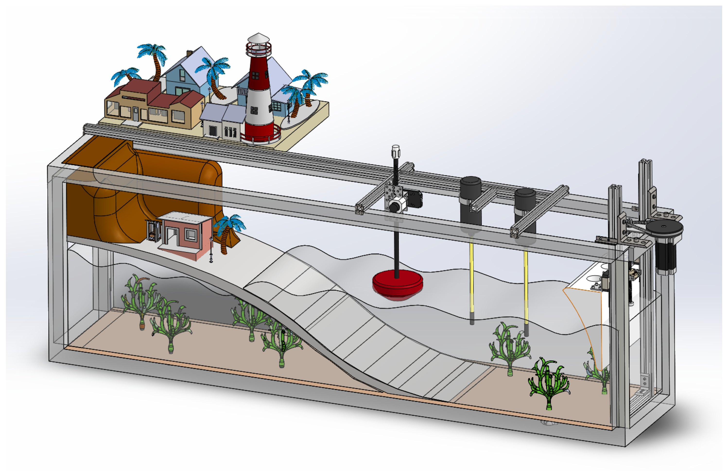
2. Design
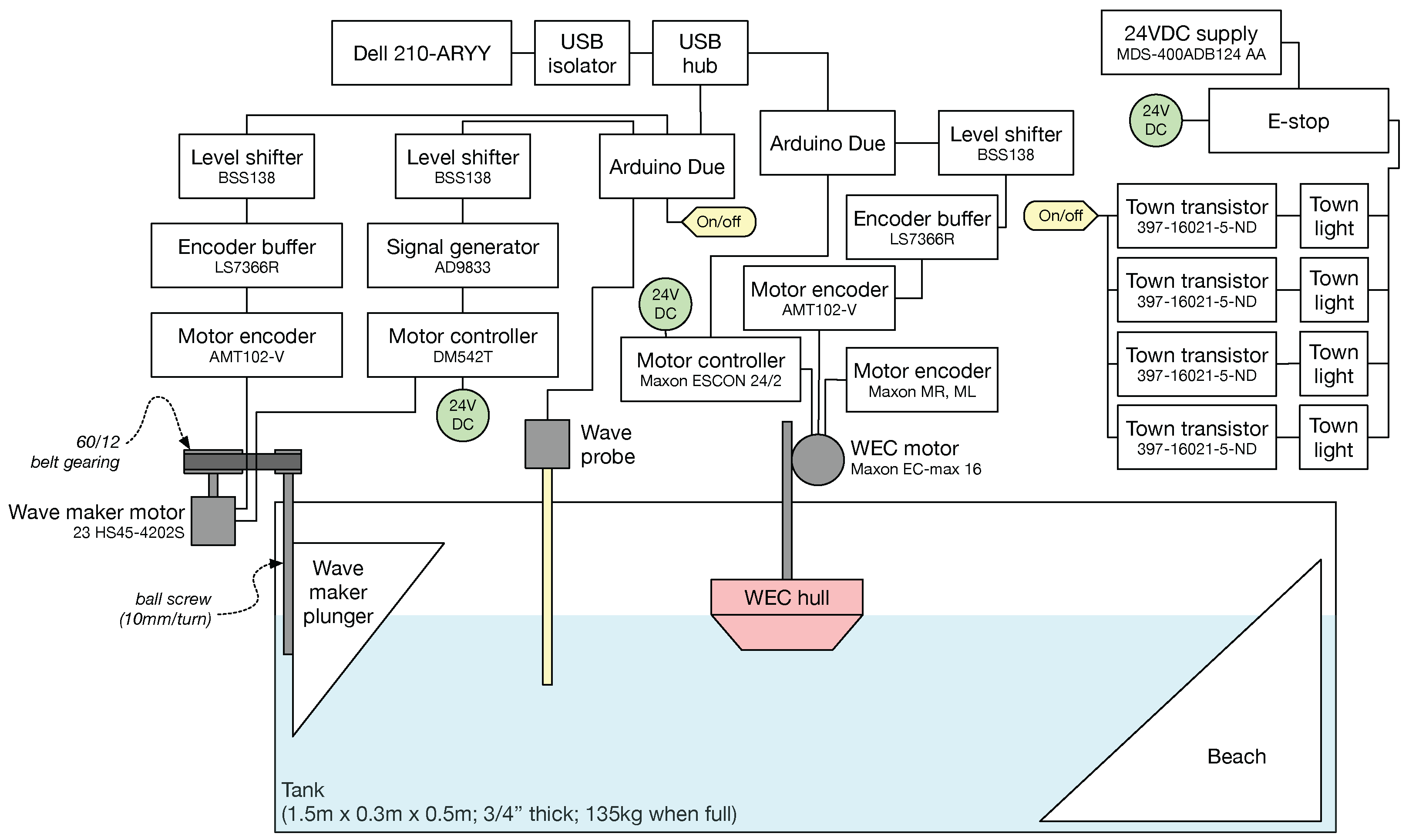
2.1. Hardware
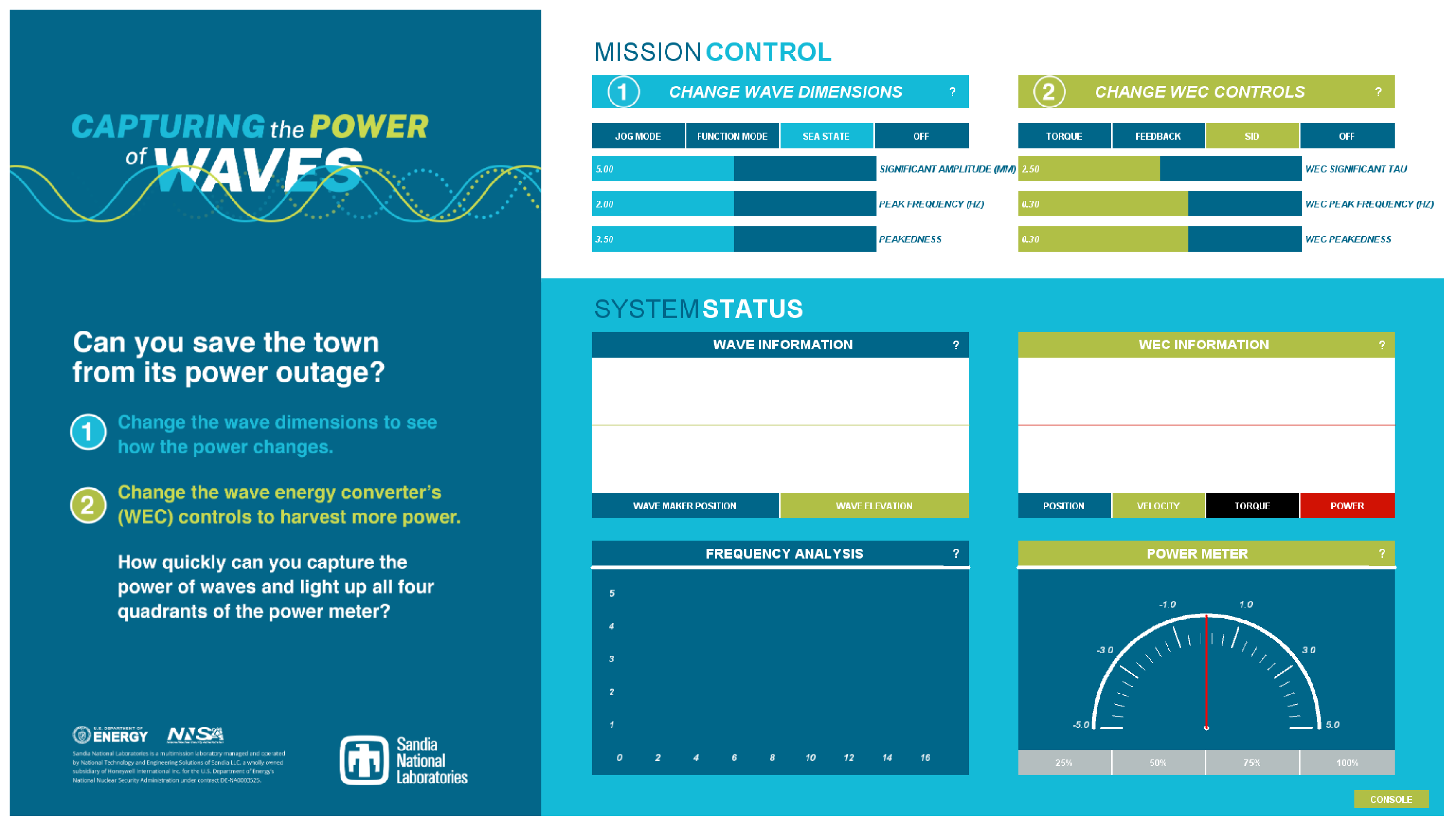
2.2. Graphical User Interface
3. Build Instructions
3.1. General
3.2. Safety
3.3. Hardware
3.4. Electronics
3.5. Software Setup
- Download the latest version of Arduino IDE and Processing IDE.
- Download the master SIWEED repository.
- Change the Sketchbook location for the Arduino IDE to \siweed\Arduino.
- Change the Sketchbook location for the Processing IDE to \siweed\Processing.
- Change the Arduino IDE board to “Arduino Due Programming Port”.
- Upload the sketches to the Arduinos.
- A more detailed version of these instructions can be found in the README file of the repository.
4. Operating Instructions
- Power on the wave tank, ensuring any kill switches are closed and any pinch points are clear.
- Open processing.exe.
- File > Open > siweedGUI.pde
- (optional) Edit modifiers. These are Booleans at the top of the code that will perform tasks like enabling basic mode, debugging, or data logging.
- Click “Run”.
- The GUI will open, allowing some time for it to load.
- In the console, which will either be in the GUI, made visible by pressing the console button in the bottom right corner, or in the Processing console, depending on your Boolean modifiers, unit tests should be visible that can be used to verify that everything is functioning properly. Note that the color of the console button in the GUI is representative of the serial checksum status. When the received checksum matches the calculated checksum (functioning nominally), the button will be a green/yellow. Otherwise it will be gray, indicating one of the Arduinos’ checksum statuses does not match, meaning the system is out of sync. This will result in the state of the GUI not accurately representing the state of the physical system.
5. Validation and Characterization
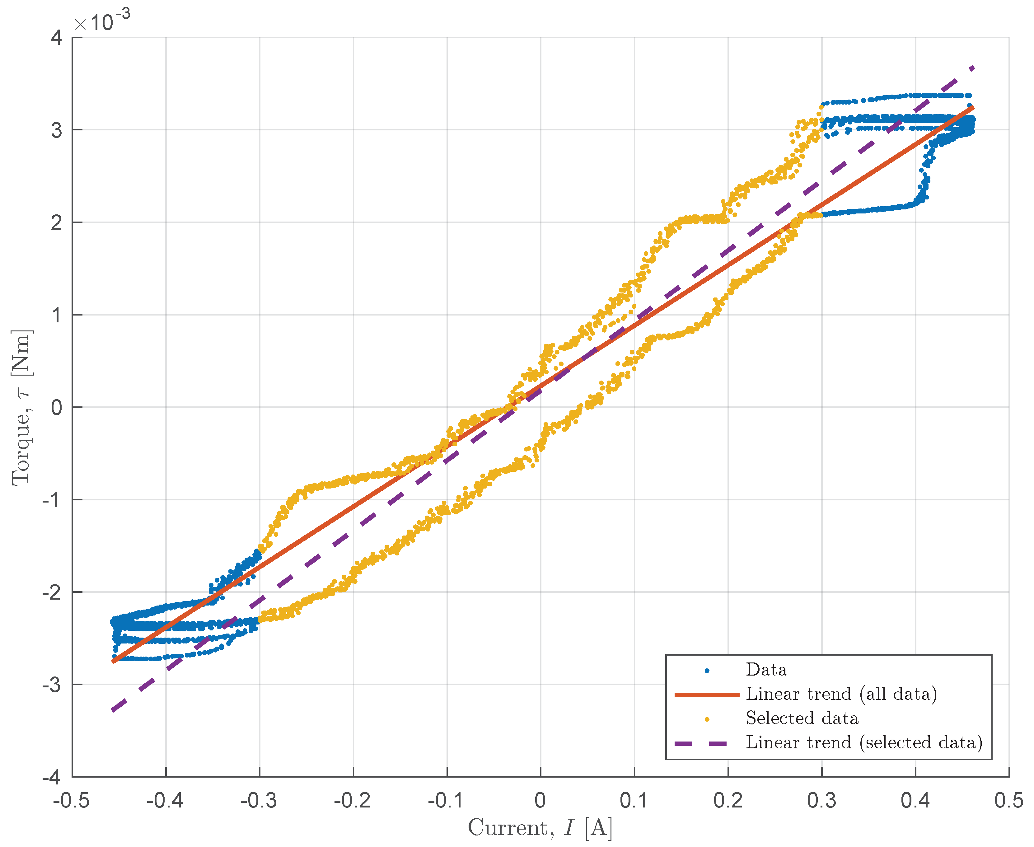
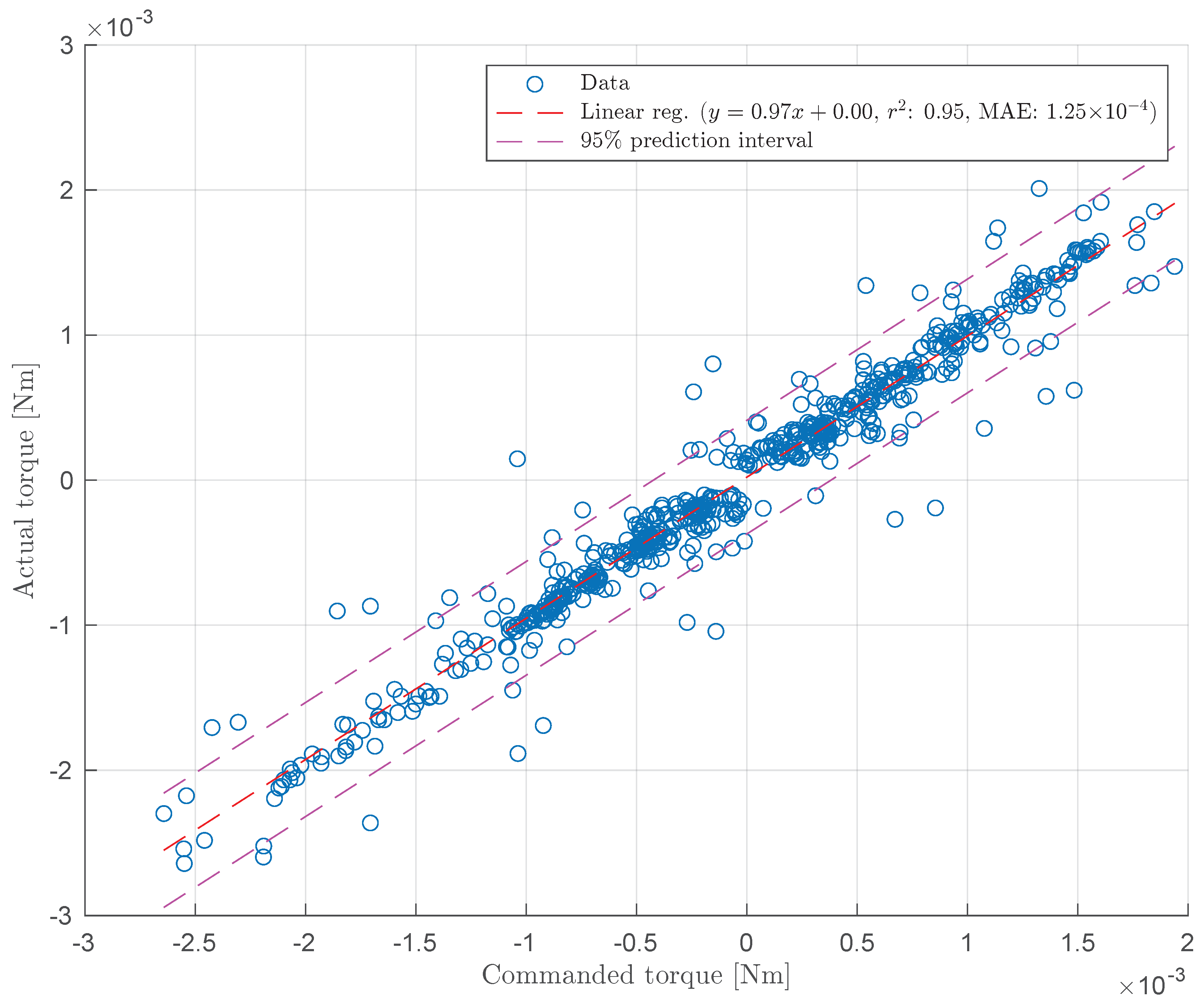
5.1. Torque Constant Verification
5.2. Friction Estimation
5.3. Wave Probes
5.4. WEC Feedback Control
6. Discussion and Conclusions
Supplementary Materials
| File Name | File Type | Description |
| Arduino/libraries | Directory | Standard Arduino libraries |
| Arduino/WaveMaker_Controller | Directory | Arduino source for wave maker |
| Arduino/WEC_Controller | Directory | Arduino source for WEC |
| CODE_OF_CONDUCT.md | Markdown | Repository code of conduct |
| contributing.md | Markdown | Repository contributing guide |
| COPYING | ASCII | Copyright |
| documentation | Directory | Journal paper; electrical diagrams |
| educational_material.md | Markdown | Teacher/student material and guide |
| matlabExamples | Directory | Simple MATLAB analysis examples |
| miniWaveModel.slx | Simulink | Simple Simulink model for prototyping |
| Processing | Directory | Graphic user interface code |
| README.md | Markdown | Basic information about the project |
Author Contributions
Funding
Data Availability Statement
Acknowledgments
Conflicts of Interest
Abbreviations
| SIWEED | Sandia Interactive Wave Energy Education Display |
| WEC | wave energy converter |
| GUI | graphic user interface |
| JONSWAP | Joint North Sea Wave Project |
| CAD | computer-aided design |
| PWM | pulse width modulation |
| SPI | serial peripheral interface |
| SID | system identification |
| IDE | integrated development environment |
| USB | universal serial bus |
| PD | proportional derivative |
| RMS | root mean square |
| LED | light-emitting diode |
References
- Hagerman, G.; Scott, G. Mapping and Assessment of the United States Ocean Wave Energy Resource; Technical Report 1024637; Electric Power Research Institute (EPRI): Palo Alto, CA, USA, 2011. [Google Scholar] [CrossRef]
- Clément, A.; McCullen, P.; Falcão, A.; Fiorentino, A.; Gardner, F.; Hammarlund, K.; Lemonis, G.; Lewis, T.; Nielsen, K.; Petroncini, S.; et al. Wave energy in Europe: Current status and perspectives. Renew. Sustain. Energy Rev. 2002, 6, 405–431. [Google Scholar] [CrossRef]
- de O. Falcão, A.F. Wave energy utilization: A review of the technologies. Renew. Sustain. Energy Rev. 2010, 14, 899–918. [Google Scholar] [CrossRef]
- Bacelli, G.; Coe, R.G. Comments on control of wave energy converters. IEEE Trans. Control Syst. Technol. 2021, 29, 478–481. [Google Scholar] [CrossRef]
- Coe, R.G.; Bacelli, G.; Forbush, D. A practical approach to wave energy modeling and control. Renew. Sustain. Energy Rev. 2021, 142, 110791. [Google Scholar] [CrossRef]
- Unger, M.L. Creating a Flexible, Web-Enabled Learning and Research Facility at the MIT Towing Tank. Ph.D. Thesis, Massachusetts Institute of Technology, Cambridge, MA, USA, 2006. [Google Scholar]
- JBA Trust. Wave Tank. Available online: https://www.jbatrust.org/about-the-jba-trust/how-we-help/physical-models/wave-tank/ (accessed on 23 May 2025).
- Ivan. New Educational Tank in the National Museum of Scotland’s Energy Laboratory. Available online: http://www4.edesign.co.uk/2016/07/new-tank-at-the-national-museum-of-scotlands-new-energy-laboratory/ (accessed on 23 May 2025).
- International Federation of Automatic Control. Development of an Interactive Wave Energy Exhibition Tank to Demonstrate Energy-Maximising Control. Available online: https://sites.ifac-control.org/activityfund/reports-of-recent-projects/development-of-an-interactive-wave-energy-exhibition-tank-to-demonstrate-energy-maximising-control (accessed on 23 May 2025).
- Ryu, S.; Kim, M.; Kinnas, S.A.; Kang, J.H. Development Of Web Based Numerical Wave Tank And Java Applets As An Advanced Tool For Teaching Wave Mechanics. In Proceedings of the ASEE Annual Conference, Nashville, TN, USA, 22–25 June 2003; pp. 8–432. [Google Scholar]
- Huynh, T.; Hou, G.; Wang, J. Communicating Wave Energy: An Active Learning Experience for Students. Am. J. Eng. Educ. 2016, 7, 37–46. [Google Scholar] [CrossRef]
- Satriawan, M.; Rosmiati, R. Simple floating ocean wave energy converter: Developing teaching media to communicating alternative energy. JPPS J. Penelit. Pendidik. Sains 2022, 12, 1–13. [Google Scholar] [CrossRef]
- Satriawan, M.; Rosmiati; Hariyono, E.; Kholiq, A. Ocean wave energy learning project (OWELP): A program to communicate alternative energy technology. Res. Sci. Technol. Educ. 2024, 1–24. [Google Scholar] [CrossRef]
- NextGenScience. Next Generation Science Standards. Available online: https://www.nextgenscience.org/ (accessed on 23 May 2025).
- Hasselmann, K.; Barnett, T.; Bouws, E.; Carlson, H.; Cartwright, D.; Enke, K.; Ewing, J.; Gienapp, H.; Hasselmann, D.; Kruseman, P.; et al. Measurements of wind-wave growth and swell decay during the Joint North Sea Wave Project (JONSWAP). Erganzungsheft zur Dtsch. Hydrogr. Z. Reihe A 1973, A8, 1–95. [Google Scholar]
- Hyun, J.M. Simplified analysis of a plunger-type wavemaker performance. J. Hydronautics 1976, 10, 89–94. [Google Scholar] [CrossRef]
- Coe, R.G.; Bacelli, G.; Patterson, D.; Wilson, D.G. Advanced WEC Dynamics & Controls FY16 Testing Report; Technical Report SAND2016-10094; Sandia National Labs: Albuquerque, NM, USA, 2016. [Google Scholar]
- Bacelli, G.; Coe, R.G.; Patterson, D.; Wilson, D. System Identification of a Heaving Point Absorber: Design of Experiment and Device Modeling. Energies 2017, 10, 472. [Google Scholar] [CrossRef]


| Control Mode | Input Parameters |
|---|---|
| Jog | Position, z [mm] |
| Function | Amplitude, A [mm] |
| Frequency, f [Hz] | |
| Sea state | Significant wave height, [mm] |
| Peak frequency, [Hz] | |
| Peakedness, [ ] |
| Group | Designator | Component | Number | Cost per Unit [USD] | Total Cost [USD] | Source |
|---|---|---|---|---|---|---|
| Electronics | USB isolator | ADUM4160 100MA USB ISOLATOR BRD | 1 | 34.95 | 34.95 | Digikey |
| Electronics | Arduino Due | Arduino Due | 2 | 37.4 | 74.8 | Digikey |
| Electronics | Level Shifter | BSS138 | 3 | 3.49 | 10.47 | Adafruit |
| Electronics | Encoder Buffer | Single LS7366R Quadrature Encoder Buffer | 2 | 28.65 | 57.3 | SuperDroid Robots |
| Electronics | Encoder | AMT102-V | 2 | 23.86 | 47.72 | Digikey |
| Electronics | WEC Motor Controller | ESCON Module 24/2, 4-Q servo controller for DC/EC motors, 2/6 A, 10–24 VDC | 1 | 89.39 | 89.39 | Maxon |
| Electronics | WEC Motor Controller MotherBoard | ESCON Module 24/2 Motherboard | 1 | 87 | 87 | Maxon |
| Electronics | WEC Motor | Maxon EC-max 16, 283828 | 1 | 190.45 | 190.45 | Maxon |
| Electronics | Wavemaker Motor Controller | StepperOnline DM542T | 1 | 19.9 | 19.9 | StepperOnline |
| Electronics | Wavemaker Motor | StepperOnline 23HS45-4204S | 1 | 33.92 | 33.92 | StepperOnline |
| Electronics | Power Supply | MDS-400ADB24AA | 1 | 164.19 | 164.19 | Digikey |
| Electronics | E-stop | EAO 84-5040.0040 | 1 | 53.95 | 53.95 | Digikey |
| Electronics | Inferred Limit | 485-2168 | 1 | 5.95 | 5.95 | Digikey |
| Electronics | Wave Probe | OSSI-010-002E Wave Staff | 2 | 1075 | 2150 | OSSI |
| Electronics | Project Enclosure | BOX ABS/PC GRY 19.68”L X 15.74”W | 1 | 122.65 | 122.65 | Digikey |
| Electronics | Signal Generator | AD9833 Function Generator | 1 | 8.95 | 8.95 | ProtoSupplies |
| Electronics | Transistor | MOSFET N-CH 30V 120A TO220 | 5 | 1.12 | 5.6 | Digikey |
| Electronics | Town Transistor | STMicroelectronics STP160N3LL | 1 | 1.85 | 1.85 | Digikey |
| Electronics | Town LED Expansion Hub | Just-Plug JP5702 | 1 | 16.99 | 16.99 | Amazon |
| Electronics | Town LED Lights and Hub Kit | Just-Plug JP5700 | 1 | 20.99 | 20.99 | Amazon |
| Other | Touchscreen Laptop | Dell 120-ARYY | 1 | 2200 | 2200 | Dell |
| Other | 3/4 inch Acrylic Tank (1.5 m × 0.3 m × 0.5 m) | 1 | 1460 | 1460 | Custom |
Disclaimer/Publisher’s Note: The statements, opinions and data contained in all publications are solely those of the individual author(s) and contributor(s) and not of MDPI and/or the editor(s). MDPI and/or the editor(s) disclaim responsibility for any injury to people or property resulting from any ideas, methods, instructions or products referred to in the content. |
© 2025 by the authors. Licensee MDPI, Basel, Switzerland. This article is an open access article distributed under the terms and conditions of the Creative Commons Attribution (CC BY) license (https://creativecommons.org/licenses/by/4.0/).
Share and Cite
Ross, N.; Heileman, D.; Motes, A.G.; Fomukong, A.; Bacelli, G.; Spencer, S.J.; Forbush, D.D.; Dullea, K.; Coe, R.G. A Portable Wave Tank and Wave Energy Converter for Engineering Dissemination and Outreach. Hardware 2025, 3, 5. https://doi.org/10.3390/hardware3020005
Ross N, Heileman D, Motes AG, Fomukong A, Bacelli G, Spencer SJ, Forbush DD, Dullea K, Coe RG. A Portable Wave Tank and Wave Energy Converter for Engineering Dissemination and Outreach. Hardware. 2025; 3(2):5. https://doi.org/10.3390/hardware3020005
Chicago/Turabian StyleRoss, Nicholas, Delaney Heileman, A. Gerrit Motes, Anwi Fomukong, Giorgio Bacelli, Steven J. Spencer, Dominic D. Forbush, Kevin Dullea, and Ryan G. Coe. 2025. "A Portable Wave Tank and Wave Energy Converter for Engineering Dissemination and Outreach" Hardware 3, no. 2: 5. https://doi.org/10.3390/hardware3020005
APA StyleRoss, N., Heileman, D., Motes, A. G., Fomukong, A., Bacelli, G., Spencer, S. J., Forbush, D. D., Dullea, K., & Coe, R. G. (2025). A Portable Wave Tank and Wave Energy Converter for Engineering Dissemination and Outreach. Hardware, 3(2), 5. https://doi.org/10.3390/hardware3020005