Abstract
A variety of events such as high-altitude electromagnetic pulses, extreme solar storms, and coordinated cyber attacks could result in a catastrophic loss of infrastructure on a continental or global scale. The lengthy repair of critical infrastructure creates a need for alternative fuels such as wood gas. Wood gas is produced by heating wood in a low-oxygen environment and can be used to power combustion engines. This work investigates a novel wood chipper, designed as an energy-efficient tool for producing wood gas stock, wood chips, aiming to speed up the transition to alternative fuel. A prototype is built and tested to determine the energy efficiency and production rate of the device. The results suggest that the wood chipper could produce one cord of wood chips, 3.6 m3, in less than a day and is a viable alternative to other manual wood-processing methods. In addition, the global scaling up of production of the wood chipper is considered, indicating that the mass production of the wood chipper could accelerate the transition of wood gas production methods from manual to machine-driven immediately after a catastrophic event.
1. Introduction
The infrastructure that provides power to civilization comprises an intricate web of generation and distribution. Although it is robust, it is not impervious to catastrophe [1,2]. An event that caused long-term damage to global electricity production could have devastating knock-on effects. It would shut down the infrastructure that produces complex items and services, such as vehicles and the internet. Without electricity, essentials such as food and water could not be harvested or transported at scale, posing a risk of mass famine [3]. The risk of a global catastrophic infrastructure loss (GCIL) scenario underscores the need for alternative energy sources and their role in ensuring food security.
Various events have potential to cause a GCIL scenario, including the following: high-altitude detonation of nuclear weapons, causing electromagnetic pulses (HEMPs) [4,5], solar storms [6,7], coordinated cyber [8,9] and physical attacks [10,11], and extreme pandemics. Given the risk of these events, there are several efforts towards the mitigation of threats and building resilience. Previous work has investigated the most essential challenges, such as feeding everyone [12,13,14]. Non-food needs and protection of equipment have also been explored [15,16]. In addition, a need for alternative fuels has been identified, namely gasified wood, that can be harvested without industry and is compatible with combustion engines [12,15,17].
After a catastrophe, repair of generators and the electrical infrastructure would likely begin right away (except in the case of an extreme pandemic). In the interim, alternative fuels, such as the conversion of biomass to wood gas, could provide life-saving services such as food transportation and medical power. For example, many diesel engines can be run in a dual-fuel mode with 50–78% of the total fuel being wood gas, and the rest being diesel [18,19,20,21]. Wood gas is produced by heating wood with a restricted oxygen supply in devices known as gasifiers. Several wood gasifier designs suitable for disaster scenarios could serve this purpose [22,23,24].
Processing enough wood to provide fuel for humanity’s needs without industrial equipment, however, remains an unexplored and significant challenge. The purpose of this study is to present an open-source design of a wood chipper for GCIL scenarios. Figure 1 shows the wood chipper in the context of such a scenario. Comparable devices are pruning loppers, axes, and manual hydraulic log splitters, costing around USD 40, USD 25, and USD 150, respectively. The device presented costs around USD 500, but is capable of higher production rates with less input energy. Table 1 shows the relative advantages and limitations between these options.
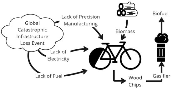
Figure 1.
Diagram of a wood chipper for biofuel production in a global catastrophic loss of infrastructure scenario.

Table 1.
Comparison of relative limitations and advantages of human-powered wood-chipping devices.
A wood chipper is designed, built, and tested to produce wood chips for biofuel during a GCIL scenario. Design requirements are developed given the supply and machining limitations in such scenarios. Analytical models are created to validate the chip size and cutting force of the chipper. Testing, despite large uncertainties, provides rough agreement with theoretical models, providing estimates on cutting production as well as information on the physical limits of the chipper. Scaling the production of wood chippers in a GCIL scenario based on current supply of parts is also considered.
2. Design
The wood chipper design for this application must balance a variety of factors such as supply chain constraints, usability, and modularity, while also meeting the physical requirements needed to produce wood for a gasifier. The product requirements and rationale are shown in Table 2.
Table 2.
Assembly-level requirements and rationale for a wood chipper design for a GCIL scenario.
Small-scale gasifiers, like those used for vehicles, use wood chunks from 1 × 0.5 × 0.5 to 8 × 6 × 5 cm range [25,26]. However, the fuel size depends on the gasifier design and can range from sawdust to whole trees [25,27,28]. Uniformity is also a factor, with more-uniform biomass leading to higher efficiency [29]. Therefore, the wood chipper will aim to create uniform chips with a size appropriate for vehicle-based gasifiers [30] (requirement 1).
Building and repairing the wood chipper will be challenging without industry. Machining and factory equipment use electric motors and control systems, such as computer numerical control (CNC) and general processing control. This limits the complexity of machined parts and therefore the construction of the wood chipper will use battery-powered or hand-powered equipment (see requirement 8). Due to this constraint, the design will only use simple custom parts and off-the-shelf parts with large quantities in stock globally (see requirement 7). In addition, the wood chipper is expected to be operated until there are sufficient wood chips and gasifiers manufactured to power a gasifier-powered wood chipper (or modified wood chipping automobile), put conservatively at 3 months (see requirement 5).
To make the wood chipper widely applicable, it will be powered and operated by one individual (see requirements 2 and 3). To be a viable alternative to other manual wood-cutting tools—like axes, which are cheap and abundant—the wood chipper must be able to produce significantly more for the same or less labor. An average individual can produce half of a cord of firewood in 8 h; with experience, this may increase to one cord (1.2 × 1.2 × 2.4 m) a day according to 19th century firewood practices [31]. Firewood used in 19th century America consisted of 1.2 m long chunks, which is much larger than those used in a typical modern gasifier but is also unusable for stoves of the era [32]. A bucksaw and saw horse were used to cut firewood to stove length, but the rates of production for this step are not well documented [32].
Modern reports of manually gathering and cutting wood vary considerably; one stated a production rate of 100 kg of wood in 1.5 h while burning 350 kilocalories [33]. At this rate, 0.75 m3 or 1/6 of a cord could be gathered in 8 h with 1870 kilocalories burned. Using a chainsaw and ax, this increases to around one cord a day, although the wood is split into large chunks [34].
The intensive labor of reducing firewood to a smaller size supports the need for an efficient chipping device. The wood chipper proposed in this paper aims to be capable of producing one cord of chips in 8 h while powered by an “average” individual (see requirement 6). The energy from a cord of chips is equivalent to 136–813 L (36–215 gallons) of gasoline, depending on the density of the species of wood [35,36]. This fuel could power a gasified pickup truck for 1438–8639 km (894–5368 miles) [37] or produce 21–125 cords of chips [38] from a conventional chipper, such as the one presented here, if powered by a combustion engine.
2.1. Functional Description
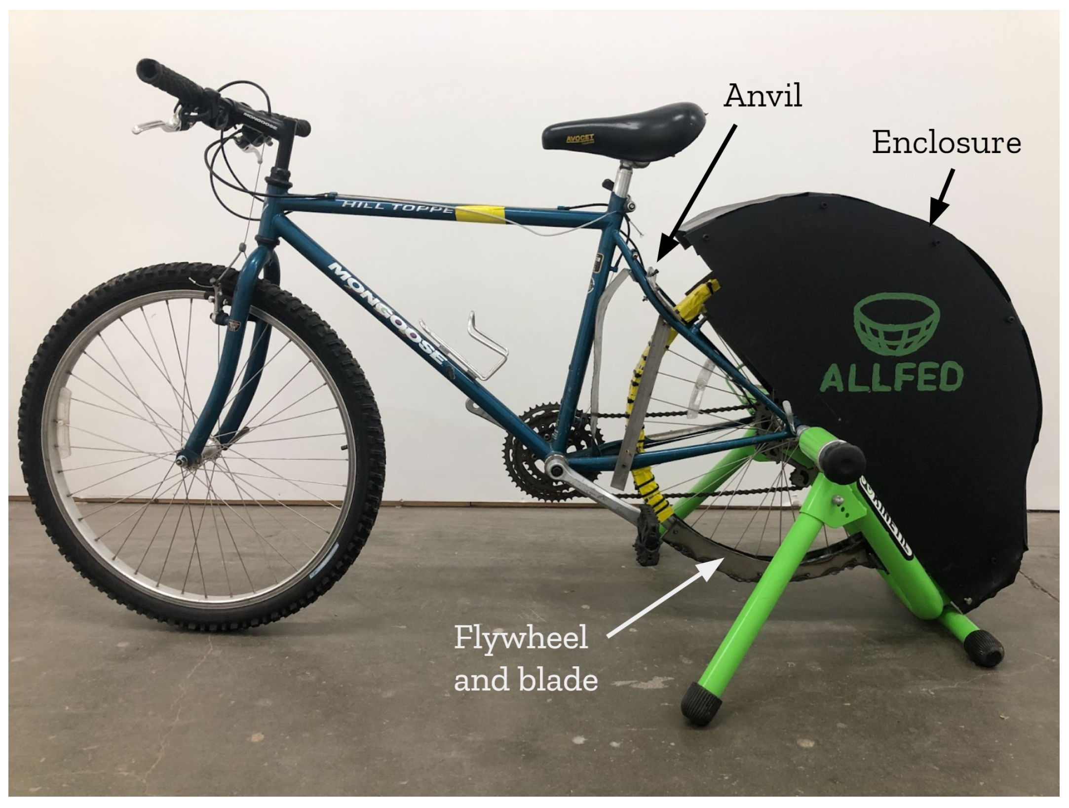
Given the requirements, a prototype of a wood chipper was constructed and tested, as shown in Figure 2. The major components are a bicycle, an exercise bike stand, a weighted wheel with a blade, an anvil for the blade to strike against, and covers for safety. In the order mentioned, the estimated costs for these items are as follows: USD 100, USD 50, USD 75, USD 75, and USD 125. It is possible to power the bicycle and feed the wood chipper at the same time, fulfilling requirement 2. The wood chipper can be broken down by removing the rear wheel and then transported by one person (requirement 3). Because it uses a bicycle as part of the drivetrain, it is possible to attach a coupling to the bottom bracket and drive it through an external source such as a motor (see requirement 4). The simple design allows for repairs to be performed with common tools and resources (see requirement 5).

Figure 2.
Side view of human-powered bicycle wood chipper prototype with major components labeled.
The custom components were machined from sheet metal and all machining was performed with hand- or battery-powered power tools to meet requirements 7 and 8. An overview of the CAD design, a bill of materials, and detailed build instructions can be found (Supplementary Materials) at the following link: https://osf.io/wus9y/ (accessed on 19 May 2024). To fulfill requirement 9, it is designed with open hardware best practices [39,40]; however, it is not a digital design because of requirements 7 and 8. The wood chipper is open source and licensed under CERN V2 S and the documentation is licensed GNU General Public License (GPL) 3.0 to provide in a disaster. The primary functional and performance requirements, 1 and 6, are discussed in the sections below.
2.2. Chipping Mechanics
Cutting and comminuting a non-brittle material like wet wood is a complicated mechanical process with a combination of shearing, tensile, bending, and torsional stresses involved [41]. The mechanical properties of wood depend on the direction of cutting, the species of the tree, where on the tree the sample was taken, the environmental conditions before cutting, and where the tree was grown [42]. For example, wood is weaker with higher moisture content [43,44].
The direction of the cutting blade relative to the grain of the wood has a significant impact on cutting force—in some cases, up to 300% [45]. Wood is weaker cutting along its fiber direction or with the grain, such as splitting wood with an ax, than compared to cross-cutting, such as sawing orthogonally [46]. Cutting speed, on the other hand, has marginal impact on the impact force required [47,48,49].
Various tests of chipping mechanics have been conducted [50,51,52,53,54,55,56,57,58,59]. Testing various sizes of branches, Hatton et al. were able to quantify a relationship between cutting force and branch area [51]. Warguła et al. found that thinner blades used less energy but required more frequent repair; although the relationship between repair cost and energy was not quantified, a 10 mm blade and 30 degree cutting angle were recommended [45].
It has also been shown that producing large chips (greater than 5 cm in length [59]), referred to as chunks, requires 0.5–1 kWh/m3 loose volume and 2–5 times less energy than producing smaller wood chips [58,59]. Wood chunks also show better storage characteristics than compared to smaller chips (in the 2–2.5 cm range) [60]. Several machines have been designed to produce wood chunks [61,62,63,64,65].
3. Building and Operating Instructions
The building instructions are organized around the components of the wood chipper: frame, flywheel, blade, anvil, and enclosure. The build requires the following tools: a sheet metal brake, clamps, files, adjustable wrench, hex key set, battery-powered drill, and a battery-powered angle grinder.
3.1. Frame
Begin with a bicycle that has a steel frame and functional drivetrain. First, drill three holes in the frame as indicated with red circles in Figure 3. These holes will be the mounting points for the anvil.
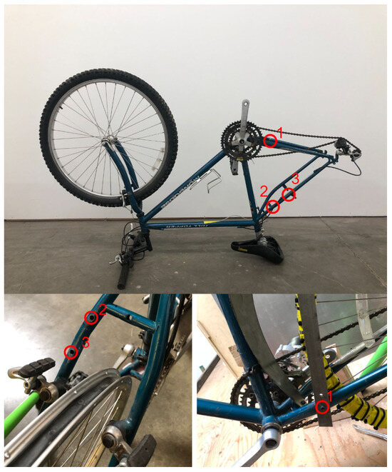
Figure 3.
Bicycle frame with hole locations numbered 1, 2, and 3 circled in red.
The hole locations will vary depending on the frame geometry. Some rough guidelines are as follows: hole 1 should allow for a near-perpendicular relationship between the anvil support and the flat surface of the anvil to best support the loading during a cut. Hole 3 should be at a point that is level with the bicycle wheel’s rim and hole 2 should be a few centimeters below that.
3.2. Flywheel
To create the flywheel, mark and drill 16 evenly spaced clearance holes for M4 bolts around the rim. Next, fabricate the flywheel sheet metal cover by cutting two pieces of 1 mm thick sheet metal with length equal to half of the circumference of the wheel to cover each half of the wheel. The width of the sheet metal pieces should allow for full coverage of the rim when bent. Cut bend reliefs to avoid warping the piece. The pattern and finished flywheel cover is shown in Figure 4.
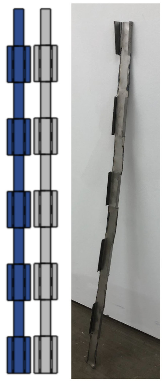
Figure 4.
Flywheel cover shown as a pattern and completed.
Once the sheet metal cover is cut, bend it to fit over each half. Bend only one side of the tabs and clamp the sheet metal to the rim. Drill through the wheel and sheet metal to create accurate through holes and repeat on the other side, as shown in Figure 5. Mark the corresponding cover halves to rim halves so they can easily be reassembled. Fill the flywheel cover with weights. Automotive wheel balancing weights were used for this prototype but any method of safely attaching weight to the bicycle wheel will work. Fasten the cover on with M4 bolts. Fill the inner side of the rim with additional weights. Duct tape and zip ties are optional and help secure the weights and rim together. The assembled flywheel with blade and support already attached is shown in Figure 6.
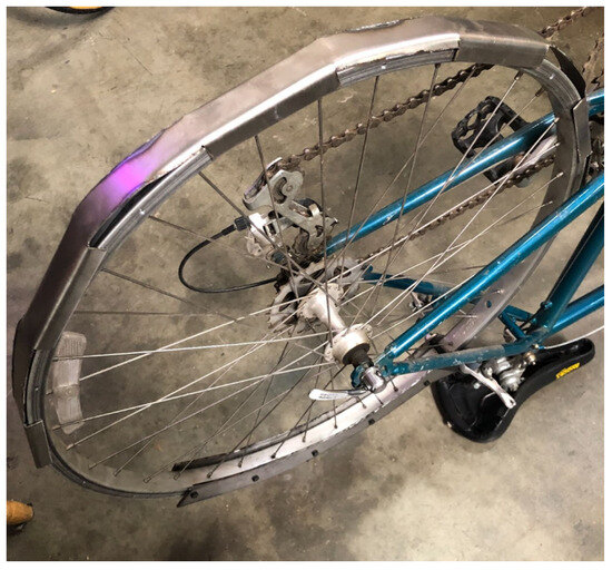
Figure 5.
Flywheel cover bent around the rim and holes drilled to match existing holes in the rim.
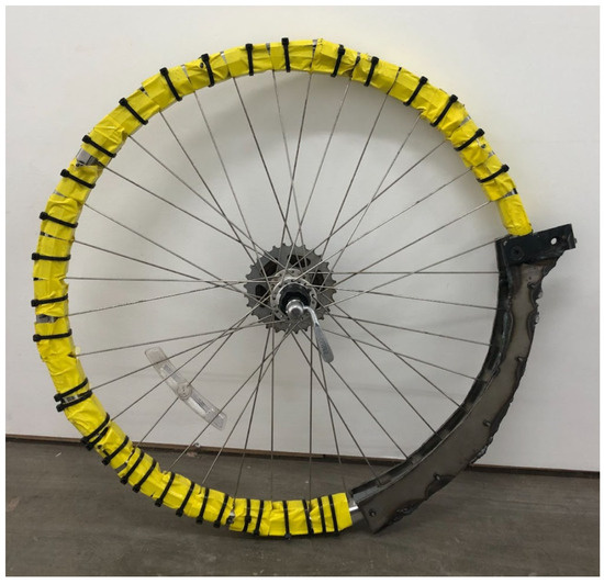
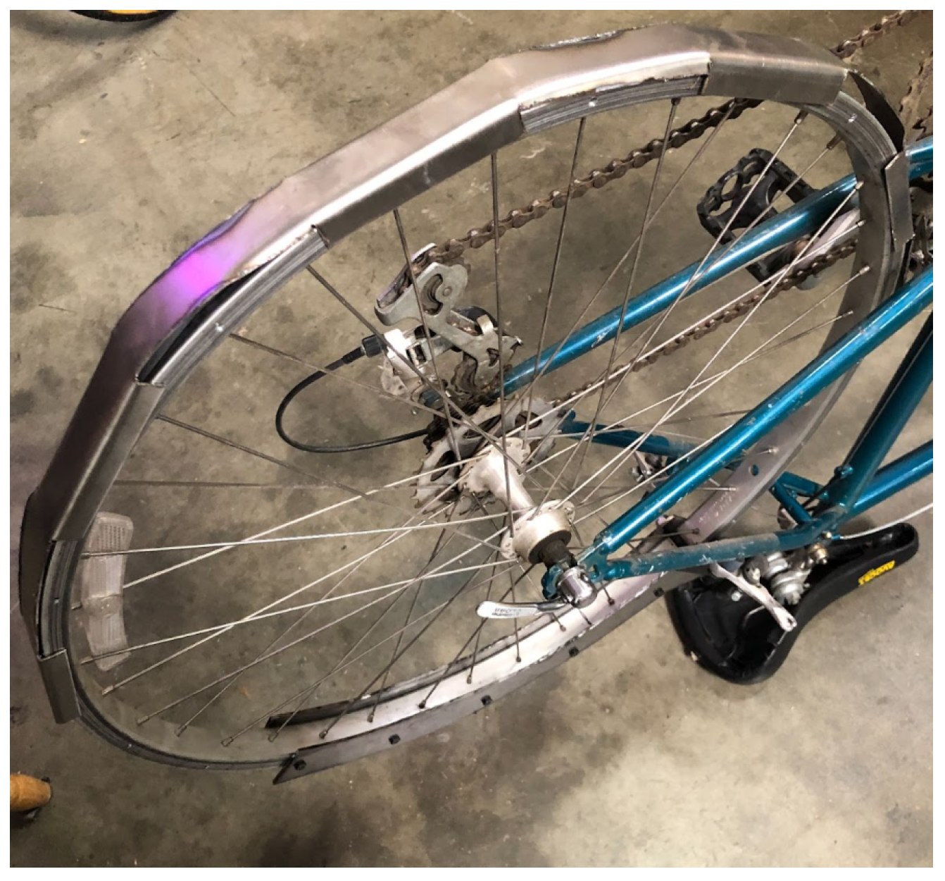
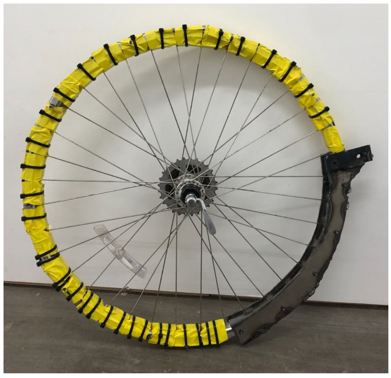
Figure 6.
Fully assembled flywheel with optional duct tape and zip ties.
3.3. Blade
The blade is bolted to the support which is cut from a 6 mm thick steel sheet. The sheet should be large enough to be bolted in 5 locations along the rim, as shown in the pattern in Figure 7. To ensure the holes on the rim are aligned with the plate, clamp the plate to the rim, then mark, and drill the holes, as shown in Figure 8. The blade support and chipper blade can then be mounted using M4 and M8 nuts and bolts, respectively.
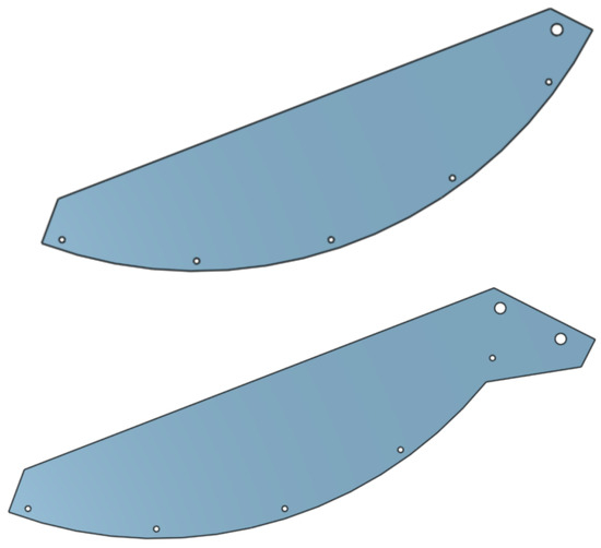
Figure 7.
Sheet metal pattern for structural steel attached to the rim and cutting blade.

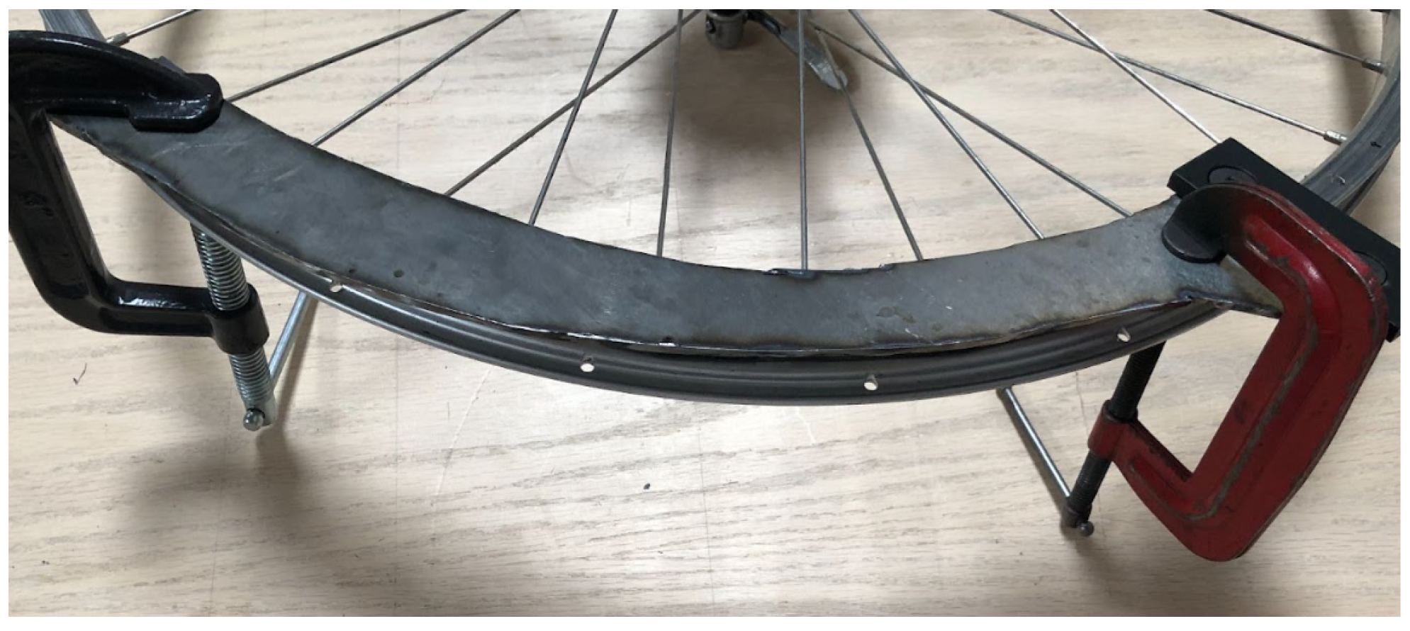
Figure 8.
Clamps used for hole alignment between the rim and supporting steel sheet.
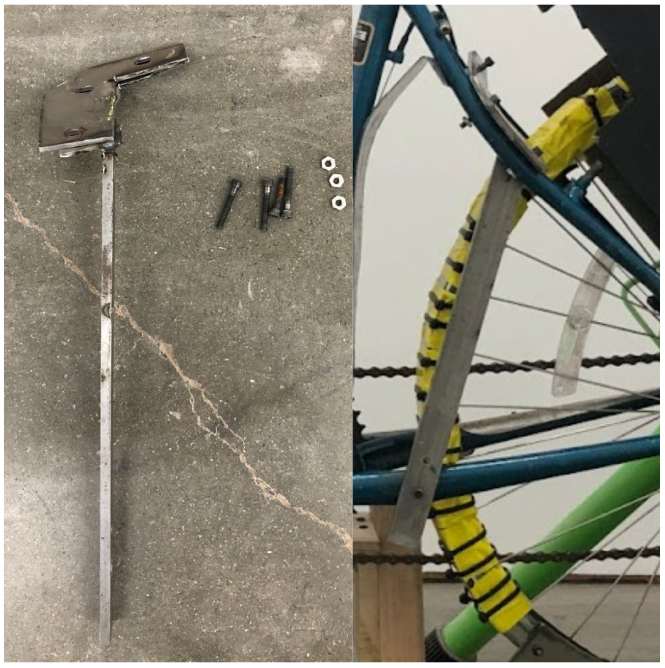
3.4. Anvil
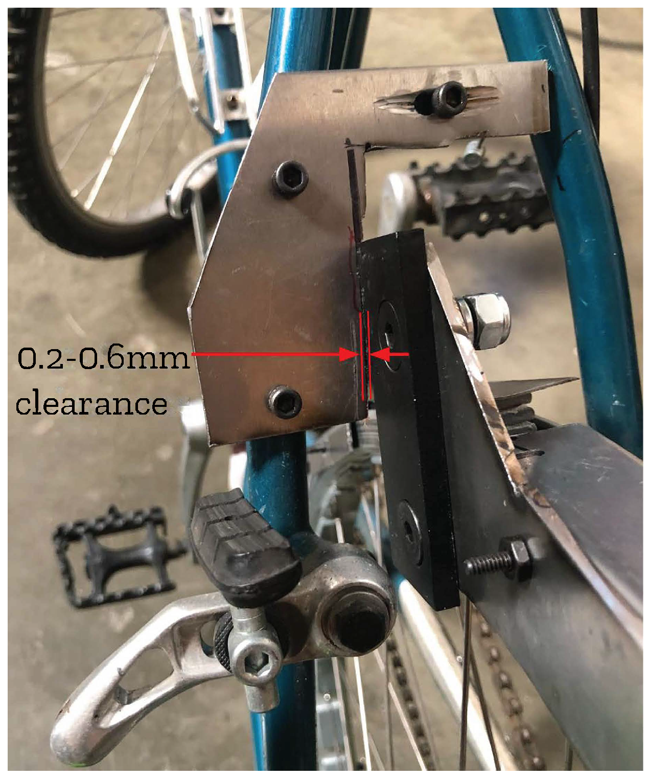
To build the anvil, align, mark, and drill a piece of 6 mm thick steel to be secured by the frame mounting holes and create 0.2–0.6 mm of clearance from the blade, as shown in Figure 9. If possible, create horizontal slots instead of holes for ease of adjustment. A round needle file can be used to create these. In addition, create an anvil support beam with a steel bar bolted into the chain stay at hole location 1 and attached to the anvil with an angle bracket, as shown in Figure 10.

Figure 9.
Anvil attached to the bicycle frame with the recommended anvil to blade cutting clearance shown.

Figure 10.
Anvil support beam shown in a side view and assembled onto the frame bolted at hole location 1.
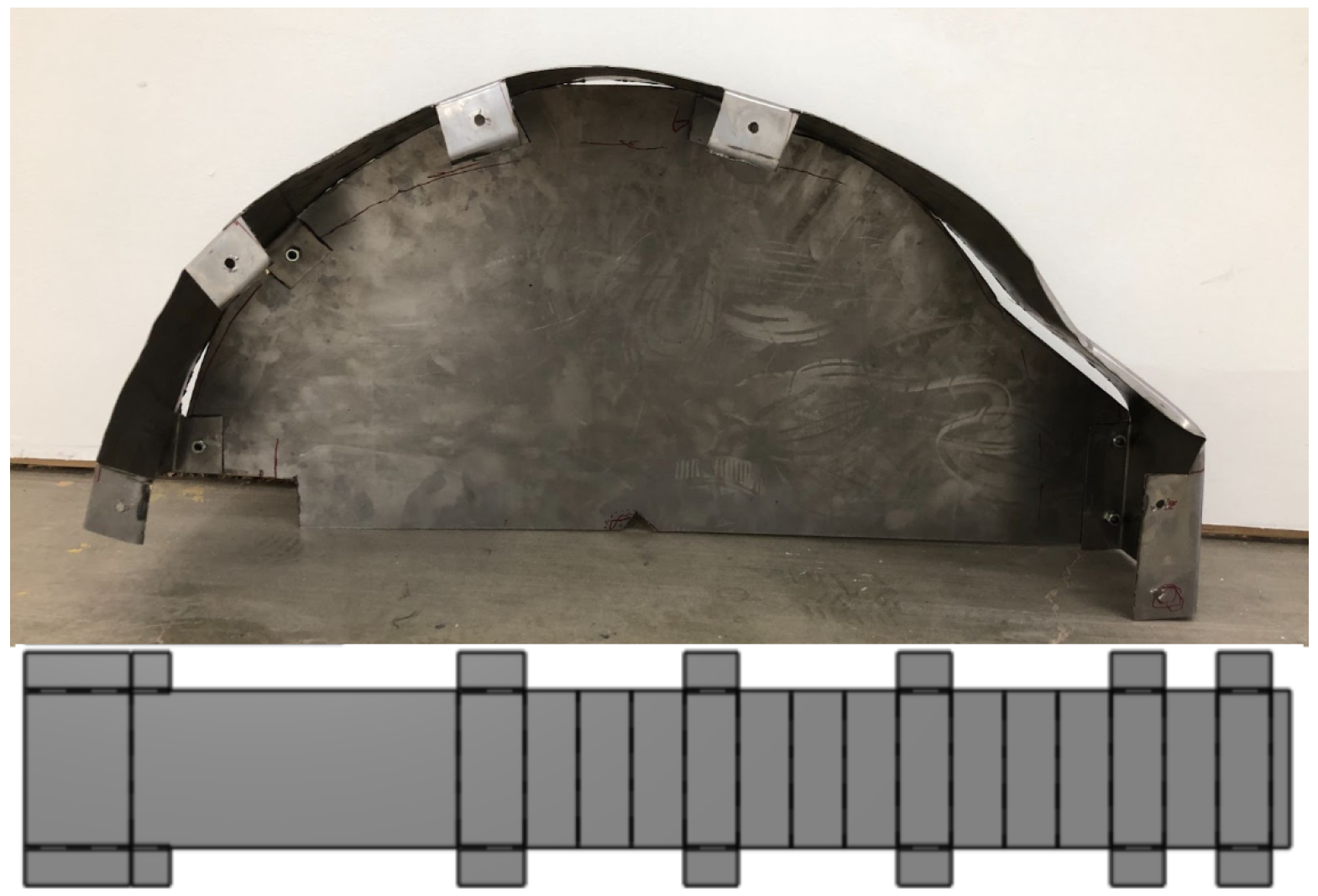
3.5. Enclosure
The enclosure is a safety component designed to prevent injury in case parts of the blade or flywheel come loose during operation. It consists of two side walls and a top sheet made from 1 mm thick sheet metal, bolted together and to the bicycle stand. The enclosure and flat pattern for the top are shown in Figure 11. The top flat pattern should have a length greater than the circumference traced by the blade as it spins around the wheel. This allows for clearance while the blade is moving. The width of the top piece and length of the side walls should be sized to fit around the drivetrain and enable bolting to the bicycle stand. This will vary greatly depending on the bicycle model, bicycle stand, and wheel size.
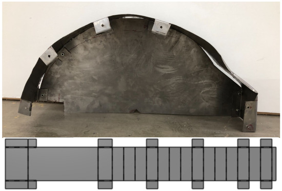
Figure 11.
Enclosure with one side wall and the top sheet flat pattern.
3.6. Operation
Before operating of the wood chipper, first collect sticks with a diameter of 1.5–2.5 cm and lengths greater than 7 cm. Pile them within arm’s reach of the bicycle while riding it. To operate the wood chipper, first put on safety goggles and utility gloves. Users should be mindful of their fingers while chopping and not bring them close to the blade. Next, ride the bicycle, pedaling at a pace that requires little effort, and shift into the highest gear. Once the wheel has reached a top speed, continue pedaling, take a stick, and feed it into the blade. Continue feeding sticks into the chipper until a desired quantity of biomass has been cut.
4. Validation
4.1. Analytical Models
Analytical models are presented to justify the need and applications of the wood chipper as well as determining the design requirements.
4.1.1. Chip Size Analysis
Smaller wood particles have higher heat and mass transfer rates because of their greater surface area [66]. The volume of the wood chip determines the total burn duration (if one compares between the same species of wood). Therefore, the volume-to-surface area ratio of a wood chip determines important burn characteristics, and can be used to compare between differently shaped wood chips.
The wood chipper in this paper produces cylindrical wood chunks versus the typical box-shaped wood chunks produced by wood chunkers. To match the burning characteristics of wood commonly used in small-scale gasifiers, the volume-to-surface area ratio of the cylindrical chunks and box-shaped chunks is compared. Specifically, a matchbox-sized chip, 4 cm × 2 cm × 1.5 cm, is compared with a range of cylindrical chunks, the shape of which will vary by the diameter and length of the stick and the cutting angle of the blade. The relevant equations for cylindrical wood chunks are shown below in Equations (1)–(3) for volume, surface area, and the volume-to-surface area ratios.
where V is the volume, is the surface area, h is the length, is the cutting angle, and r is the radius. Figure 12 compares these two shapes and highlights when the two shapes have the same surface area-to-volume ratio. Sticks between diameters 1.5 and 2.5 cm and lengths greater than 7 cm with a cutting angle between 0 and 60 degrees will burn similarly to a matchbox-sized wood chunk commonly used in vehicle gasifiers. For lengths greater than 7 cm, the ratio is constant for a given diameter and cutting angle. This is because, as the length of the stick approaches infinity, the ratio of the volume-to-surface area simplifies to Equation (4).
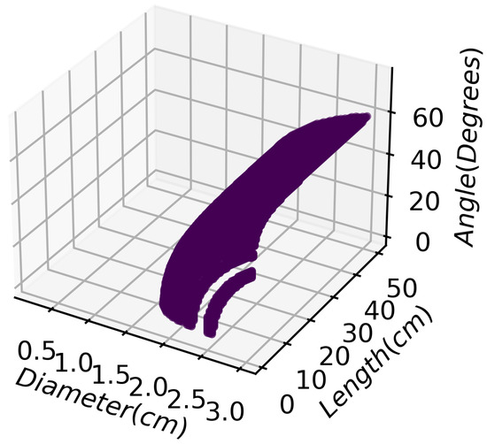
Figure 12.
Volume-to-surface area ratio of chip blocks to sticks at a range of stick diameters, lengths, and cutting angles.
This suggests that sticks that are 7 cm long will have similar burn characteristics to longer sticks. Longer sticks are preferred because they require less chopping and energy than compared to shorter sticks, but the maximum length is restricted by the type of wood as well as the design of the gasifier.
4.1.2. Wood Chipper Kinetic Energy Model
Without reserve fuel and alternative power sources, human labor will be necessary to power the wood chipper. The wood chipper can be run from a combustion engine supplied with wood gas; therefore, the laborer can replace themselves with an engine once a sufficient supply of wood chips and gasifiers are produced. Hydro and animal power may also be viable alternatives to human labor. The following will discuss a kinetic energy model of the wood chipper.
People expend anywhere from 80 to 1500 W during daily activity [67]. Turning this energy into mechanical power is efficiently and economically performed with a bicycle [68]. According to a NASA study, “healthy men” can output 200 W over an hour [69] and expend around 60 W walking at 1.3 m/s on flat ground [70]. For this paper, the energy analysis will set a rider output to 50 W, a pace assumed to be light activity that could be maintained for several hours. The rider’s output should be expected to improve as fitness improves over several days.
To produce the high forces needed to chip wood, a mechanical battery such as a flywheel is necessary to store and release mechanical energy. Previous work on human-powered flywheel machines has shown a wide variety of applications [71,72,73,74,75,76]. Other mechanisms, such as gravity batteries, hydraulics, and pneumatics, are capable of producing the needed forces but are either too inefficient or difficult to manufacture for this application.
The model compares cutting force against the diameter of the wood fed into the device. The equations outlined by Mustafa et al. are used to model the kinetic energy of a flywheel with bearing and air drag losses [77]. By including the mechanical transmission losses of the bicycle, an energy balance for the flywheel can be found.
where is the initial kinetic energy, is the windage loss, is the bearing loss, is the bicycle transmission loss, and is the final kinetic energy. To find the force output from the flywheel, it is assumed all the kinetic energy is turned into work across the cut and the final kinetic energy is equal to zero.
where W is work. With the assumption that and a known cutting distance—equal to the arc that the blade cuts during its range of motion—the output force of the flywheel blade can be found.
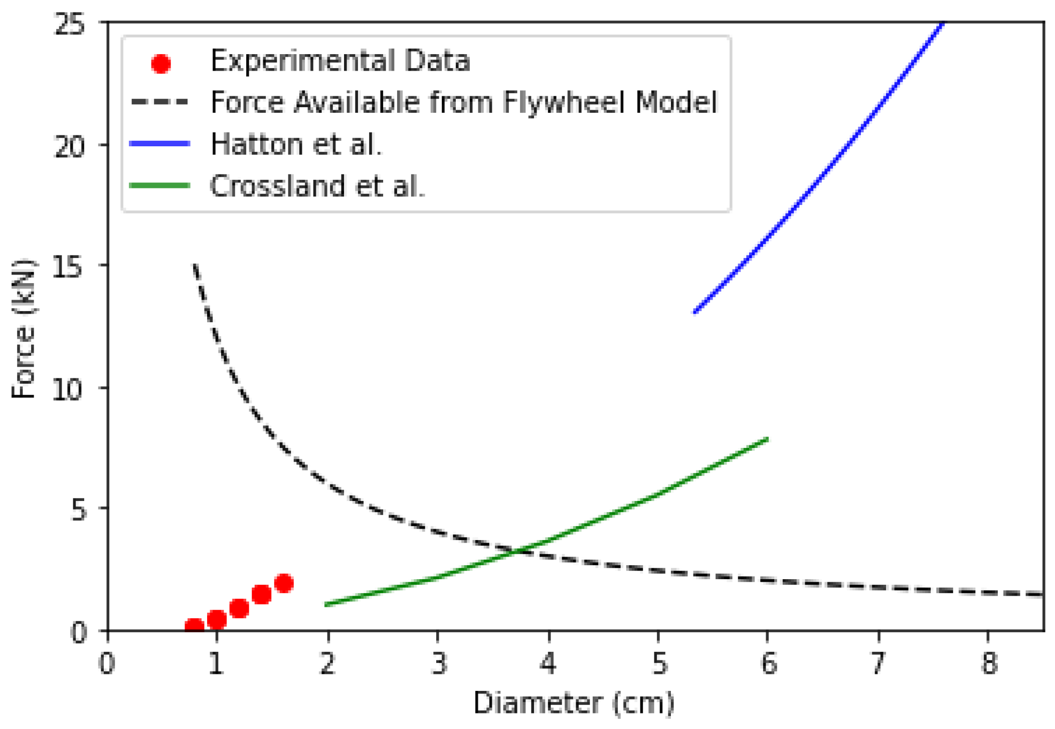
where F is the cutting force and d is the distance of path the blade makes while cutting, which is equal to . Where r is the radius of the wood and is the swept angle of the blade relative to its rotational axis. The used in the model is determined by setting the power input from the bicyclist and cutoff of at 10% of the maximum kinetic energy of the flywheel to reduce the energy lost to friction. The result of the cutting force versus the wood diameter model can be found in Figure 13. The flywheel ramp up in terms of kinetic energy and RPM (revolutions per minute) with the aforementioned 10% cutoff can be found in Figure 14.
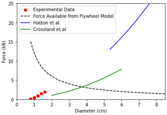
Figure 13.
Wood chipper blade cutting force versus wood diameter overlaid with data from Hatton et al. [51] and Crossland P. et al. [78].
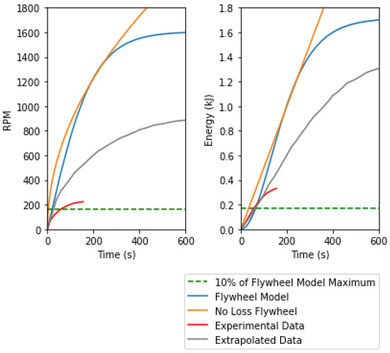
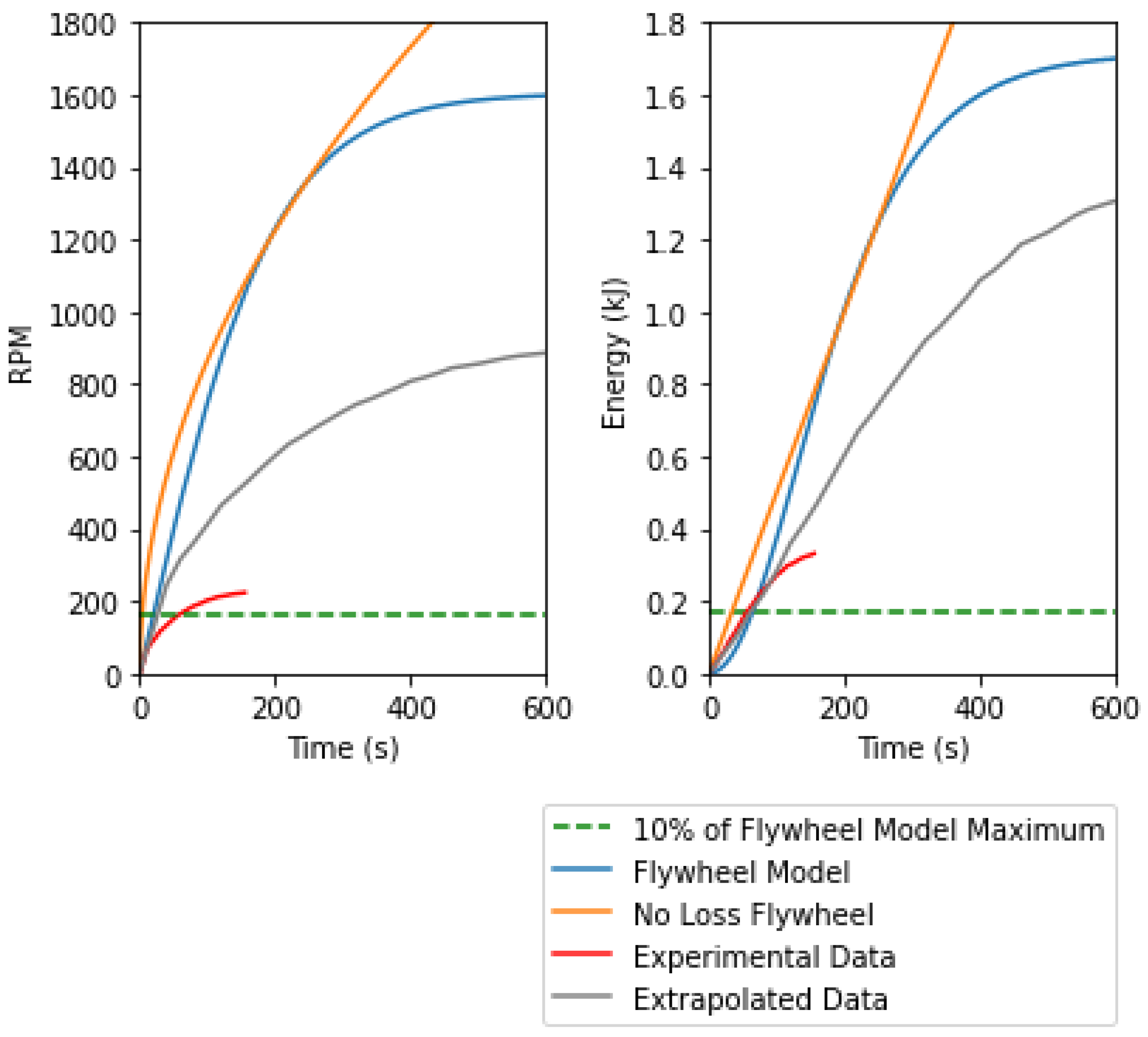
Figure 14.
Wood chipper kinetic energy versus time and wood chipper RPM versus time.
4.2. Experimental Test Setup
The experimental test setup for the wood chipper allowed for the collection of data on output cutting force and flywheel ramp-up performance. The test setup consists of a bicycle-powered wood chipper prototype, a tachometer, an electric motor, and a power supply, as shown in Figure 15.
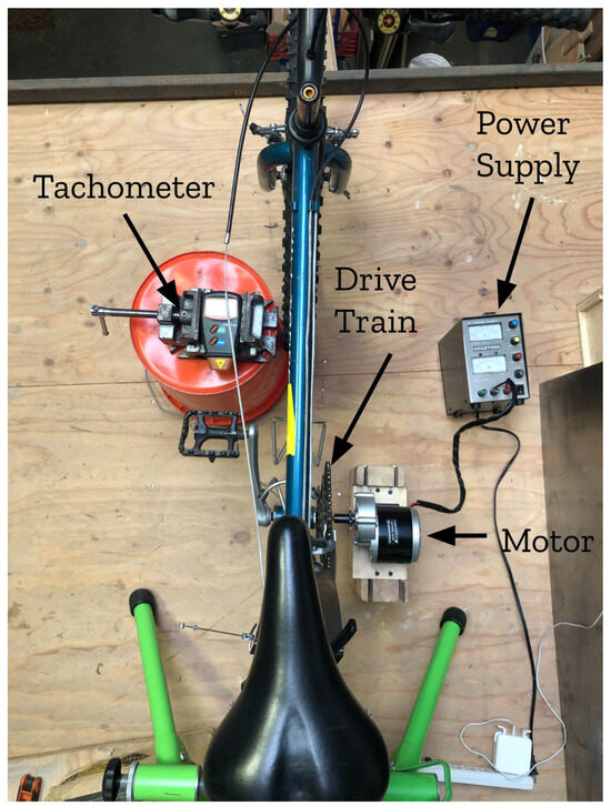
Figure 15.
Experimental test setup for the wood chipper, with major components labeled.
To determine the energy efficiency and cutting capability of the wood chipper, two tests were conducted that measured the following factors: (1) the force required to cut different sized sticks; (2) the speed and energy of the wood chipper over time with a constant power input.
4.2.1. Cutting Force
The cutting force is calculated by measuring the initial and final RPM of the flywheel with a tachometer before and after cutting a piece of wood. The input power of the rider is not measured. The tachometer is a AGPTEK model 4350282862 with a 0.05% error rate. Using the following equation, the change in RPM is equated to a change in kinetic energy, which is then used to solve for cutting force, given Equations (6) and (7).
where I is the moment area of inertia and w is the angular velocity of the flywheel.
4.2.2. Kinetic Energy
The ramp-up performance evaluates the energy of a flywheel over time given a constant input. This provides an evaluation of the energy efficiency of the system and an estimate of the total time and energy required to cut large pieces of wood that completely stop the flywheel when cut.
The ramp-up performance is measured by connecting an electric motor, supplied with a constant 50 W from a power supply to the drivetrain of the bicycle, and measuring the RPM over time using a tachometer.
4.3. Results
The results of the cutting force versus the wood diameter are shown in Figure 13 and the energy and RPM over time are shown in Figure 14.
4.3.1. Cutting Force
The calculated cutting force data are shown in Figure 13, along with peak cutting force data from two comparable experiments [51,78]. The experimental force data show a similar trend to the previous peak force data experiments, which suggests a parabolic relationship with diameter (linear with respect to area) [51,78].
The largest diameter stick cut by the wood chipper was 2.6 cm, although the force data could not be reliably measured for sticks beyond a 1.6 cm diameter. This was due to experimental setup limitations—beyond 1.6 cm diameter, the flywheel would experience dramatic changes in RPM, which the tachometer could not accurately measure. In addition, the mechanical limitations of the metal components used in the design limited the diameter of wood to under 2.6 cm to prevent bending the blade, anvil, or bicycle frame.
In the 0.8–1.6 cm diameter range, the wood chipper can cut branches near continuously, as the wood chipper climbs back up to top speed between cuts and there is no risk of damage. Between 1.5 and 2 cm is the recommended operating range for the wood chipper in order to cut near-continuously and produce wood chips of a sufficient size for a typical gasifier. This range meets the design requirement 1 of producing wood chips that are suitable for a conventional vehicle-based gasifier.
The force available from flywheel model intersects with the Crossland et al. data at a 3.6 cm diameter. The model therefore predicts that the wood chipper can produce enough force to cut up to a 3.6 cm diameter stick, given that the wood chipper is at 10% of its maximum speed with a 50 W input. The experimental data, however, show a maximum diameter of 2.6 cm, which is 1 cm less than predicted. The difference may be due to a number of factors, including a difference in input power between the model and experiment, the strength and geometry of key structural components, and cutting efficiency factors, such as the blade width, the anvil–blade distance, and the cutting angle.
4.3.2. Kinetic Energy
Given a constant 50 W input and no losses the kinetic energy of a flywheel will increase linearly over time and a flywheel with losses will tend toward some horizontal asymptote. The experimental data are asymptotic, as expected, but are only 14% efficient when compared to the theoretical no-loss condition. An efficiency of greater than 85% is expected from most flywheel energy systems [79], although there are limited data for small flywheels such as the one demonstrated in this paper. Part of this difference in efficiency can be attributed to the motor being operated at around 20% efficiency during the experiment. Adjusting the motor efficiency to 80% is shown in the extrapolated data plot, Figure 14. Another contributing factor is a suboptimal fitting motor coupler. The misaligned and slip-prone motor coupling caused a significant amount of movement and noise within the assembly. The exact amount of energy lost due to the motor coupler was not measured. Future work is needed on the design to improve both the performance and the diameter of biomass that can be processed.
The horizontal 10% maximum RPM line shows the desired operational RPM of the wood chipper. This maximum RPM remains in the linear region of the energy versus time relationship and avoids wasting excess energy due to friction. The operational RPM is used as the input of the flywheel in the previous cutting force analytical model.
With a mechanical input of 50 W, it takes around 6 s to achieve 10% maximum RPM and cut a wood chunk 1.5 cm in diameter by 50 cm long, giving a production rate of around 15 cm3/s. This assumes that each cut brings the wood chipper to a halt. At this rate, an individual could produce a cord of wood in 2.6 h, which exceeds the performance goal—requirement 6—of one cord in 8 h.
4.4. Supply Scalability Evaluation
To assess the scalability of the prototype in a GCIL scenario, the global supply of each component was investigated and the logistics of communicating, sourcing, manufacturing, and distributing were ignored. The bill of materials, shown in Table 3, is compared with current global production of the base materials, Table 4, including the small-diameter wood stock required for chipping. The limiting production material is then determined and the scaling potential of chippers estimated.
Table 3.
Wood chipper bill of materials from https://osf.io/wus9y/ (accessed on 19 May 2024). * Components are readily substitutable.
Table 4.
Global market of wood chipper base materials.
Considering the narrow design requirements of the chipper blade, it can be expected that this component will be the limiting factor in scaling the wood chipper production. In addition, when comparing the global market value of the base materials, in Table 3, the wood chipper machine’s market value is two orders of magnitude lower, suggesting chipper blades would be the limiting factor.
To approximate chipper blade production, it is assumed that each chipper costs around USD 1000, with each machine having two blades, giving a wood chipper blade production of around 774,800 units [82]. This allows for up to 387,400 bicycle chippers to be produced per year. If these bicycle wood chippers were run 24 h a day for a full year, they could produce 6,108,523,200 m3 of biomass ready for gasification.
Another limiting factor, however, is the availability of small-diameter wood suitable for the wood chipper. In 2022, 3,983,335,553 m3 of roundwood was harvested globally [81]. Slash—the biomass debris left after harvest—weighs around 11% of the total harvest and has been found to consist of around 31% of branches less than 3 cm in diameter [83]. This results in 133,362,074 m3 of small-diameter branches that are suitable for the wood chipper. Assuming this full quantity could be utilized from the current and past logging for one year, the wood chippers would comminute the stock of branches in one week and, when converted to wood gas, could produce 170 TWh or 4.2% of the current global weekly power demand [84]. This fraction of global power demand could then be used to jumpstart wood-gas-powered machinery, including larger-diameter wood chippers, and eliminate the need for manual biofuel processing.
5. Future Work
There are several areas of future work indicated by the results of this study. First, several areas of the mechanical design can be further explored by increasing the thicknesses of the main components to be able to chip larger-diameter branches, as well as improve the coupling tolerances to improve the energy efficiency. Increased thicknesses would have substantial impacts on the availability of biomass, which would increase the energy potential of the approach as well as providing some biomass for conversion to human edible food. These devices can also be used to produce wood chips for direct resilient food processing during global catastrophes, such as mushroom production [85,86] and sugar production [87]. Additional experiments can be run with various types of wood and diameters to better complete the experimental data and then integrate them with GIS analysis of the geographic distribution of available wood. Repurposing vehicles to be powered by wood gasification and power wood chipping is also important future work.
6. Conclusions
The work suggests that the chipper presented in this paper could significantly increase the production of woodchips in a GCIL scenario when compared to other manual methods. The global supply of the components of the chipper also suggest that the production of the chipper could be rapidly scaled to meet a short-term and global demand for wood gas.
The current literature, however, does not adequately quantify the energy expenditure or production rates of manual wood-processing methods; therefore, it is difficult to compare different manual methods, including the method outlined in this study. Gathering better manual wood processing data is an important next step to justify the significant investment in materials and time to produce the bicycle wood chipper compared to readily available tools.
On the onset of a GCIL scenario, an efficient human-powered method for producing wood chips can help kick-start the crucial wood gas production needed to supplement and eventually replace reserve diesel and gasoline. Manual wood-chipping methods can be replaced with wood-gas-powered wood chippers once enough wood chips and gasifiers have been produced, paving the way for biofuel-powered biofuel production. Delay in this energy transition may have significant consequences to life-saving services, making it important to have an efficient and scalable method of manually producing biofuel.
Supplementary Materials
The following supporting information can be downloaded at: https://osf.io/wus9y/.
Author Contributions
Conceptualization, H.V., D.D. and J.M.P.; methodology, H.V. and D.D.; software, H.V.; validation, H.V. and D.D.; formal analysis, H.V.; investigation, H.V.; resources, H.V. and D.D.; data curation, H.V.; writing—original draft preparation, H.V.; writing—review and editing, H.V., D.D. and J.M.P.; visualization, H.V.; supervision, D.D.; project administration, D.D.; funding acquisition, D.D. All authors have read and agreed to the published version of the manuscript.
Funding
Funding for this work was provided by ALLFED and the Thompson Endowment.
Institutional Review Board Statement
Not applicable.
Informed Consent Statement
Not applicable.
Data Availability Statement
All data and the designs of the device are available https://osf.io/wus9y/ (accessed on 19 May 2024).
Acknowledgments
The authors would like to thank Jesse Smith for their ideas, suggestions, and support.
Conflicts of Interest
The authors declare no conflicts of interest.
References
- Sun, S.; Li, G.; Bian, Y.; Bie, Z.; Hu, Q. Catastrophe Risk Management for Electric Power Distribution Systems: An Insurance Approach. CSEE J. Power Energy Syst. 2022, 9, 393–410. [Google Scholar]
- Mili, L.; Qiu, Q.; Phadke, A.G. Risk assessment of catastrophic failures in electric power systems. Int. J. Crit. Infrastruct. 2004, 1, 38–63. [Google Scholar] [CrossRef]
- Moersdorf, J.; Rivers, M.; Denkenberger, D.; Breuer, L.; Jehn, F.U. The Fragile State of Industrial Agriculture: Estimating Crop Yield Reductions in a Global Catastrophic Infrastructure Loss Scenario. Glob. Chall. 2024, 8, 2300206. [Google Scholar] [CrossRef] [PubMed]
- Wilson, C.; Foreign Affairs, D.; Division, T. High Altitude Electromagnetic Pulse (HEMP) and High Power Microwave (HPM) Devices: Threat Assessments; Congressional Research Service, Library of Congress: Washington, DC, USA, 2006. [Google Scholar]
- Pry, P.V. China: EMP Threat: The People’s Republic of China Military Doctrine, Plans, and Capabilities for Electromagnetic Pulse (EMP) Attack; EMP Task Force on National and Homeland Security: Washington, DC, USA, 2020. [Google Scholar]
- Kilpua, E.K.; Lugaz, N.; Mays, M.L.; Temmer, M. Forecasting the structure and orientation of earthbound coronal mass ejections. Space Weather 2019, 17, 498–526. [Google Scholar] [CrossRef]
- Riley, P. On the probability of occurrence of extreme space weather events. Space Weather 2012, 10. [Google Scholar] [CrossRef]
- Case, D.U. Analysis of the Cyber Attack on the Ukrainian Power Grid; Electricity Information Sharing and Analysis Center (E-ISAC): Washington, DC, USA, 2016; Volume 388, p. 3. [Google Scholar]
- Onyeji, I.; Bazilian, M.; Bronk, C. Cyber security and critical energy infrastructure. Electr. J. 2014, 27, 52–60. [Google Scholar] [CrossRef]
- Amin, M. Energy infrastructure defense systems. Proc. IEEE 2005, 93, 861–875. [Google Scholar] [CrossRef]
- Smith, R. Assault on California Power Station Raises Alarm on Potential for Terrorism. Wall Str. J. 2014. Available online: https://www.wsj.com/articles/assault-on-california-power-station-raises-alarm-on-potential-for-terrorism-1391570879 (accessed on 19 May 2024).
- Cole, D.D.; Denkenberger, D.; Griswold, M.; Abdelkhaliq, M.; Pearce, J. Feeding everyone if industry is disabled. In Proceedings of the IDRC DAVOS 2016 Integrative Risk Management-towards Resilient Cities, Davos, Switzerland, 28 August–1 September 2016. [Google Scholar]
- Breuer, L. Simulating Potential Yield If Industry Is Disabled: Applying a Generalized Linear Modelling Approach to Major Food Crops. Ph.D. Thesis, Justus-Liebig University, Giessen, Germany, 2021. [Google Scholar]
- Denkenberger, D.C.; Cole, D.D.; Abdelkhaliq, M.; Griswold, M.; Hundley, A.B.; Pearce, J.M. Feeding everyone if the sun is obscured and industry is disabled. Int. J. Disaster Risk Reduct. 2017, 21, 284–290. [Google Scholar] [CrossRef]
- Abdelkhaliq, M.; Denkenberger, D.; Griswold, M.; Cole, D.D.; Pearce, J. Providing non-food needs if industry is disabled. In Proceedings of the IDRC DAVOS 2016, Integrative Risk Management-Towards Resilient Cities, Davos, Switzerland, 28 August–1 September 2016. [Google Scholar]
- Li, J.Y. Risk Analysis and Mitigation Strategies for Preventing Corrosion during Industrial Power Failure; Nanyang Technological University: Singapore, 2021. [Google Scholar]
- Denkenberger, D.; Sandberg, A.; Tieman, R.J.; Pearce, J.M. Long-term cost-effectiveness of interventions for loss of electricity/industry compared to artificial general intelligence safety. Eur. J. Futur. Res. 2021, 9, 1–24. [Google Scholar] [CrossRef]
- Rajvanshi, A.; Joshi, M. Development and operational experience with topless wood gasifier running a 3· 75 kW diesel engine pumpset. Biomass 1989, 19, 47–56. [Google Scholar] [CrossRef]
- Sridhar, G.; Paul, P.; Mukunda, H. Biomass derived producer gas as a reciprocating engine fuel—an experimental analysis. Biomass Bioenergy 2001, 21, 61–72. [Google Scholar] [CrossRef]
- Bhattacharya, S.; Pham, H.L. A study on a multi-stage hybrid gasifier-engine system. Biomass Bioenergy 2001, 21, 445–460. [Google Scholar] [CrossRef]
- Raman, P.; Ram, N. Performance analysis of an internal combustion engine operated on producer gas, in comparison with the performance of the natural gas and diesel engines. Energy 2013, 63, 317–333. [Google Scholar] [CrossRef]
- LaFontaine, H.; Zimmerman, G.P. Construction of a Simplified Wood Gas Generator for Fueling Internal Combustion Engines in a Petroleum Emergency; Technical Report; Oak Ridge National Lab. (ORNL): Oak Ridge, TN, USA, 1989. [Google Scholar]
- Food and Agriculture Organization. Woodgas as an Engine Fuel; Forestry Division Publication 72; FAO: Rome, Italy, 1988. [Google Scholar]
- Stassen, H.E. Small-Scale Biomass Gasifiers for Heat and Power: A Global Review; The World Bank: Washington, DC, USA, 1995. [Google Scholar]
- Saravanakumar, A.; Haridasan, T.; Reed, T.B.; Bai, R.K. Experimental investigations of long stick wood gasification in a bottom lit updraft fixed bed gasifier. Fuel Process. Technol. 2007, 88, 617–622. [Google Scholar] [CrossRef]
- Ingneiorsvetenskapsakademien; Biomass Energy Foundation. Generator Gas: The Swedish Experience [with Wood]-Gas 1939–1945; Biomass Energy Foundation: Stockholm, Sweden, 1998. [Google Scholar]
- Bryden, K.M.; Ragland, K.W. Numerical modeling of a deep, fixed bed combustor. Energy Fuels 1996, 10, 269–275. [Google Scholar] [CrossRef]
- Moscahlaidis, G.; Cundiff, J.; Mason, J. Chunkwood combustion for on-farm applications. Bioresour. Technol. 1991, 36, 113–119. [Google Scholar] [CrossRef]
- Belonio, A.T. Rice Husk Gas Stove Handbook; Central Philippine University: Iloilo City, Philippines, 2005. [Google Scholar]
- Wood, M.; Branch, P. Wood Gas as Engine Fuel; Food and Agriculture Organization of the United Nations: Rome, Italy, 1986; Volume 133. [Google Scholar]
- Peck, R.H. Wood for War Emergency Fuel; Soils Department, Missouri Agricultural Experiment Station, and the Soil Conservation Service: Columbia, MI, USA, 1942; Volume 133. [Google Scholar]
- White, F.G. Wood fires and firewood. In The Chronicle; Early American Industries Association: Hebron, MD, USA, 2001; Volume 54. [Google Scholar]
- Rob West. Energy History: How Much Wood Can Be Cut in a Day? 2018. Available online: https://thundersaidenergy.com/downloads/energy-history-how-much-wood-can-be-cut-in-a-day/ (accessed on 15 January 2024).
- Charlie Brumbaugh. How Much Wood Can the Average Person Expect to Chop in a Day? 2018. Available online: https://outdoors.stackexchange.com/questions/13751/how-much-wood-can-the-average-person-expect-to-chop-in-a-day#::text=2%20or%203%20cords%20a,%2C%20split%2C%20haul%20and%20stack (accessed on 15 January 2024).
- Artemio, C.P.; Maginot, N.H.; Serafín, C.U.; Rahim, F.P.; Guadalupe, R.Q.J.; Fermín, C.M. Physical, mechanical and energy characterization of wood pellets obtained from three common tropical species. PeerJ 2018, 6, e5504. [Google Scholar] [CrossRef] [PubMed]
- Babu, S.P. Biomass gasification for hydrogen production–process description and research needs. In Technology Report from IEA Bioenergy Task 33 for ExCo56; IEA Bioenergy: Didcot, UK, 2005; p. 11. [Google Scholar]
- Kris De Decker. Wood Gas Vehicles: Firewood in the Fuel Tank. 2010. Available online: https://solar.lowtechmagazine.com/2010/01/wood-gas-vehicles-firewood-in-the-fuel-tank/#::text=coupe.%20It%20consumes-,50%20kilograms,-(110%20pounds)%20of (accessed on 30 September 2023).
- Spinelli, R.; Magagnotti, N. Determining long-term chipper usage, productivity and fuel consumption. Biomass Bioenergy 2014, 66, 442–449. [Google Scholar] [CrossRef]
- Oberloier, S.; Pearce, J.M. General design procedure for free and open-source hardware for scientific equipment. Designs 2017, 2, 2. [Google Scholar] [CrossRef]
- Gibb, A. Building Open Source Hardware: DIY Manufacturing for Hackers and Makers; Pearson Education: London, UK, 2015. [Google Scholar]
- Schubert, G.; Bernotat, S. Comminution of non-brittle materials. Int. J. Miner. Process. 2004, 74, S19–S30. [Google Scholar] [CrossRef]
- Chuchala, D.; Orlowski, K.A.; Sandak, A.; Sandak, J.; Pauliny, D.; Barański, J. The effect of wood provenance and density on cutting forces while sawing Scots pine (Pinus sylvestris L.). BioResources 2014, 9, 5349–5361. [Google Scholar] [CrossRef]
- Martin, T.A.; McCallion, H. Knife slicing of wood across the grain. Wood Sci. Technol. 1996, 30, 397–410. [Google Scholar] [CrossRef]
- Dumail, J.F.; Olofsson, K.; Salmén, L. An analysis of rolling shear of spruce wood by the Iosipescu method. Holzforschung 2000, 420–426. [Google Scholar] [CrossRef]
- Warguła, Ł.; Wojtkowiak, D.; Kukla, M.; Talaśka, K. Modelling the process of splitting wood and chipless cutting Pinus sylvestris L. wood in terms of designing the geometry of the tools and the driving force of the machine. Eur. J. Wood Wood Prod. 2023, 81, 223–237. [Google Scholar] [CrossRef]
- Woodson, G.E. Tool Forces and Chip Formation in Orthogonal Cutting of Loblolly Pine; Southern Forest Experiment Station, Forest Service, US Department of Agriculture: Asheville, NC, USA, 1970; Volume 52. [Google Scholar]
- FRANZ, N.C. An Analysis of the Wood Cutting Process [With Illustrations]; Published for the Engineering Research Institute; University of Michigan Press: Ann Arbor, MI, USA, 1958. [Google Scholar]
- Kivimaa, E.; Murto, J. Investigations on Factors Affecting the Chipping of Pulp Wood; VTT Technical Research Centre of Finland: Espoo, Finland, 1949. [Google Scholar]
- McKenzie, W.M. Fundamental Analysis of the Wood-Cutting Process. Ph.D. Thesis, The University of Michigan, Ann Arbor, MI, USA, 1961. [Google Scholar]
- Harvánek, P.; Kováč, J.; Melicherčík, J. Analysis of cutting force in the process of chipless felling wood. Wood Res. 2021, 66, 153–160. [Google Scholar] [CrossRef]
- Hatton, B.; Pot, G.; Bouzgarrou, B.C.; Gagnol, V.; Gogu, G. Experimental determination of delimbing forces and deformations in hardwood harvesting. Croat. J. For. Eng. J. Theory Appl. For. Eng. 2015, 36, 43–53. [Google Scholar]
- Georges, R.; Auchet, S.; Méausoone, P.J. Experimental study about the effects of disc chipper settings on the distribution of wood chip size. Biomass Bioenergy 2011, 35, 843–852. [Google Scholar] [CrossRef]
- King, M.; Vincent , J.F.V. Fracture energy during cleaving of Pinus radiata. Eur. J. Wood Wood Prod. 1998, 56, 259–265. [Google Scholar] [CrossRef]
- Nati, C.; Spinelli, R. How blade wear of chippers can affect fuel consumption and wood chip size distribution. In Proceedings of the Forest Engineering: Meeting the Needs of the Society and the Environment, FORMEC, Padova, Italy, 11–14 July 2010; pp. 11–14. [Google Scholar]
- Talić, H. The force required for the creation of wood cuttings. In IOP Conference Series: Materials Science and Engineering; IOP Publishing: Bristol, UK, 2021; Volume 1208, p. 012024. [Google Scholar]
- Özden, S.; Ennos, A.R.; Cattaneo, M.E. Transverse fracture properties of green wood and the anatomy of six temperate tree species. For. Int. J. For. Res. 2017, 90, 58–69. [Google Scholar] [CrossRef]
- Eriksson, G.; Bergström, D.; Nordfjell, T. The state of the art in woody biomass comminution and sorting in Northern Europe. Int. J. For. Eng. 2013, 24, 194–215. [Google Scholar] [CrossRef]
- Danielsson, B.O. Evaluation of chunkwood as wood fuel and the Swedish experimental machine. In Proceedings of the International Energy Agency Conference on Production, Storage and Utilization of Wood Fuels, Uppsala, Sweden, 6–7 December 1988. 214p. [Google Scholar]
- Danielsson, B.O. Chunkwood as wood fuel. Biomass 1990, 22, 211–228. [Google Scholar] [CrossRef]
- Baadsgaard-Jensen, J. Storage and energy economy of chunk and chip piles. In Research Report-Exploitation of Marginal Forest Resources for Fuel; Danish Institute of Forest Technology: Taastrup, Denmark, 1988. [Google Scholar]
- Arola, R.A.; Winsauer, S.A.; Radcliffe, R.C.; Smith, M.R. Chunkwood production: A new concept. For. Prod. J. 1983, 33, 43–51. [Google Scholar]
- Sturos, J.B. Teardrop Chunker Performance; US Department of Agriculture, Forest Service, North Central Forest: Missoula, MT, USA, 1989. [Google Scholar]
- Baadsgaard-Jensen, J. Comminution and Application of Forest Wood Residues; Skovteknisk Institut: Copenhagen, Denmark, 1988. [Google Scholar]
- Heikka, T.; Piirainen, K. Power consumption of small chippers. In Folia Forestalia; Institutum Forestale Fenniae: Helsinki, Finland, 1981; Volume 496. [Google Scholar]
- Nurmi, J. Chunking and Chipping with Conescrew Chipper; Metsäntutkimuslaitos: Helsinki, Finland, 1986. [Google Scholar]
- Patel, V.R.; Upadhyay, D.S.; Patel, R.N. Gasification of lignite in a fixed bed reactor: Influence of particle size on performance of downdraft gasifier. Energy 2014, 78, 323–332. [Google Scholar] [CrossRef]
- Morton, D.J. Human Locomotion and Body Form: A Study of Gravity and Man; Williams & Wilkins: Philadelphia, PA, USA, 1952. [Google Scholar]
- Wilson, D.G.; Schmidt, T. Bicycling Science; MIT Press: Cambridge, MA, USA, 2020. [Google Scholar]
- Roth, E.M. Bioenergetics of Space Suits for Lunar Exploration. NASA SP-84; NASA Special Publication; NASA: Washington, DC, USA, 1966; Volume 84. [Google Scholar]
- Shimomura, K.; Murase, N.; Osada, T.; Kime, R.; Anjo, M.; Esaki, K.; Shiroishi, K.; Hamaoka, T.; Katsumura, T. A study of passive weight-bearing lower limb exercise effects on local muscles and whole body oxidative metabolism: A comparison with simulated horse riding, bicycle, and walking exercise. Dyn. Med. 2009, 8, 1–8. [Google Scholar] [CrossRef] [PubMed]
- Zakiuddin, K.; Singh, M.; Modak, J. Mathematical Modeling & Simulation of Chaff Cutter Energized by human-powered Flywheel Motor. In Advances in Mechanism and Machine Science: Proceedings of the 15th IFToMM World Congress on Mechanism and Machine Science 15; Springer: Krakow, Poland, 2019; pp. 3551–3559. [Google Scholar]
- Baitule, H.; Maheshwary, P.; Modak, J. Human-Powered Flywheel Motor (HPFM): A Review. In Advancement in Materials, Manufacturing and Energy Engineering, Vol. I: Select Proceedings of ICAMME 2021; Springer: Singapore, 2022; pp. 209–224. [Google Scholar]
- Modak, J.; Bapat, A. Formulation of a generalized experimental model for a manually driven flywheel motor and its optimization. Appl. Ergon. 1994, 25, 119–122. [Google Scholar] [CrossRef] [PubMed]
- Khope, P.; Modak, J. Development and performance evaluation of a human-powered flywheel motor operated forge cutter. Int. J. Sci. Technol. Res. 2013, 2, 146–149. [Google Scholar]
- Khope, P.; Modak, J. Design of experimental set-up for establishing empirical relationship for chaff cutter energized by human-powered flywheel motor. J. Agric. Technol. 2013, 9, 779–791. [Google Scholar]
- Bokade, U.; Kazi, Z.S.; Mehta, G.D. Design Furthermore, Development of Manually Energized Water Distillation Device. Int. J. Mech. Eng. Robot. Res. (IJMERR) 2013, 2, 264–268. [Google Scholar]
- Amiryar, M.E.; Pullen, K.R.; Nankoo, D. Development of a high-fidelity model for an electrically driven energy storage flywheel suitable for small-scale residential applications. Appl. Sci. 2018, 8, 453. [Google Scholar] [CrossRef]
- Crossland, P.; Murphy, G.; Martin, G.; Dean, M. Energy and force requirements for six pruning shear designs. N. Z. For. 1997, 42, 22–26. [Google Scholar]
- Pe na-Alzola, R.; Sebastián, R.; Quesada, J.; Colmenar, A. Review of flywheel based energy storage systems. In Proceedings of the 2011 International Conference on Power Engineering, Energy and Electrical Drives, Malaga, Spain, 11–13 May 2011; pp. 1–6. [Google Scholar]
- Grand View Research. Inc. Grand View Research. 2023. Available online: https://www.grandviewresearch.com/ (accessed on 19 February 2024).
- Food and Agriculture Organization of the United Nations STAT Forestry Production and Trade. 2022. Available online: https://www.fao.org/faostat/en/#data/FO (accessed on 19 February 2024).
- Landmark Tools. Popular Questions We Get Asked about Wood Chippers. 2023. Available online: https://landmarktools.com/collections/wood-chippers#::text=Small%20and%20medium%20compact%20wood,ranges%20between%20%243%2C000%20to%20%2410%2C000 (accessed on 23 February 2024).
- Ghaffariyan, M.R.; Apolit, R. Harvest residues assessment in pine plantations harvested by whole tree and cut-to-length harvesting methods (a case study in Queensland, Australia). Silva 2015, 16, 113–122. [Google Scholar]
- Ritchie, H.; Rosado, P.; Roser, M. Energy Production and Consumption. Our World in Data. 2020. Available online: https://ourworldindata.org/energy-production-consumption (accessed on 19 May 2024).
- Denkenberger, D.; Pearce, J.M. Feeding Everyone No Matter What: Managing Food Security after Global Catastrophe; Academic Press: Cambridge, MA, USA, 2014. [Google Scholar]
- Balan, V.; Zhu, W.; Krishnamoorthy, H.; Benhaddou, D.; Mowrer, J.; Husain, H.; Eskandari, A. Challenges and opportunities in producing high-quality edible mushrooms from lignocellulosic biomass in a small scale. Appl. Microbiol. Biotechnol. 2022, 106, 1355–1374. [Google Scholar] [CrossRef] [PubMed]
- Throup, J.; Martínez, J.B.G.; Bals, B.; Cates, J.; Pearce, J.M.; Denkenberger, D.C. Rapid repurposing of pulp and paper mills, biorefineries, and breweries for lignocellulosic sugar production in global food catastrophes. Food Bioprod. Process. 2022, 131, 22–39. [Google Scholar] [CrossRef]


Disclaimer/Publisher’s Note: The statements, opinions and data contained in all publications are solely those of the individual author(s) and contributor(s) and not of MDPI and/or the editor(s). MDPI and/or the editor(s) disclaim responsibility for any injury to people or property resulting from any ideas, methods, instructions or products referred to in the content. |
© 2024 by the authors. Licensee MDPI, Basel, Switzerland. This article is an open access article distributed under the terms and conditions of the Creative Commons Attribution (CC BY) license (https://creativecommons.org/licenses/by/4.0/).