
Evaluation of Spatial Distribution of Crystallinity Induced by Local Heating Using Low-Frequency Raman Spectroscopy on Polyether Ether Ketone (PEEK)

 ,
,  and
and 
Abstract
1. Introduction
2. Materials and Methods
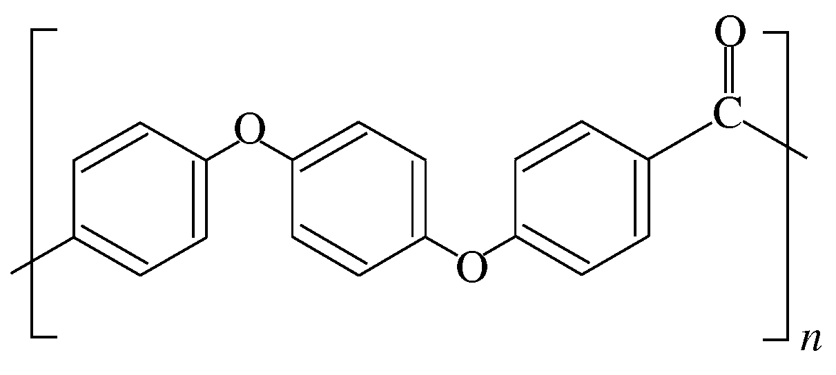
2.1. Sample Preparation
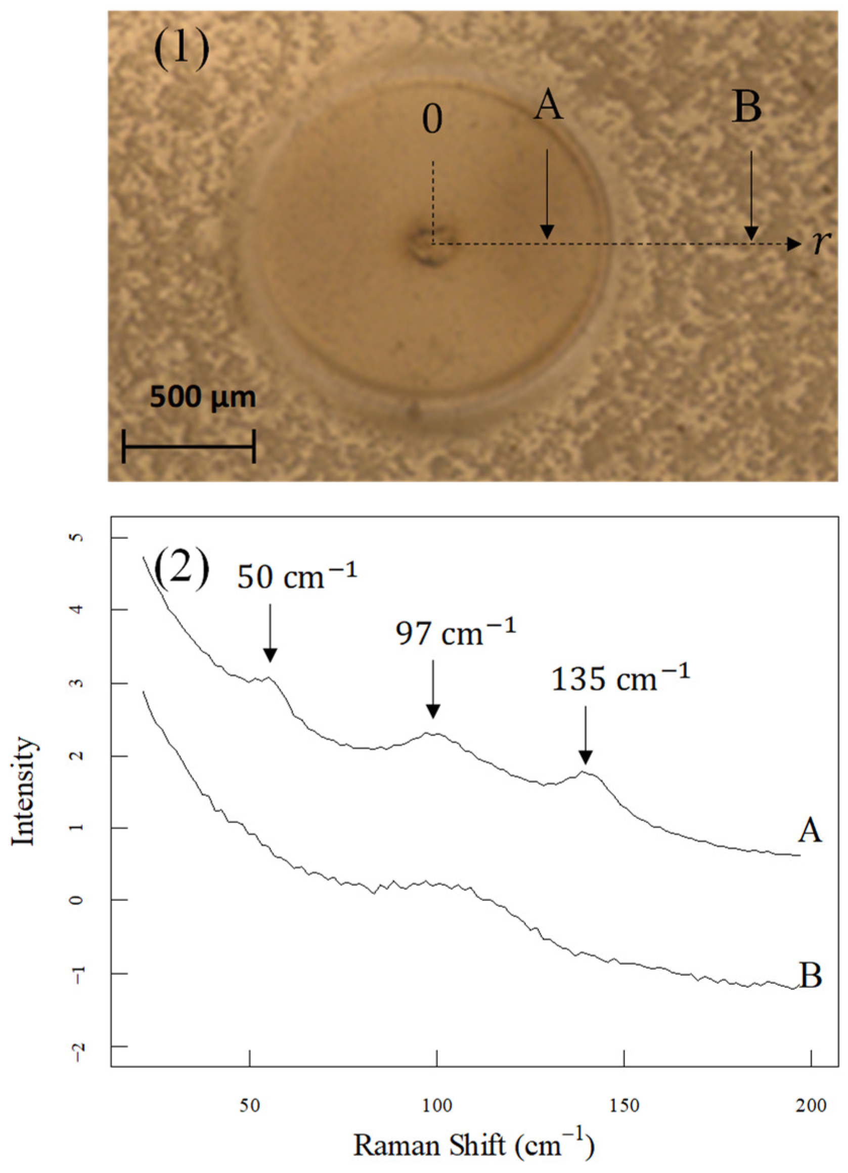
2.2. Experiments
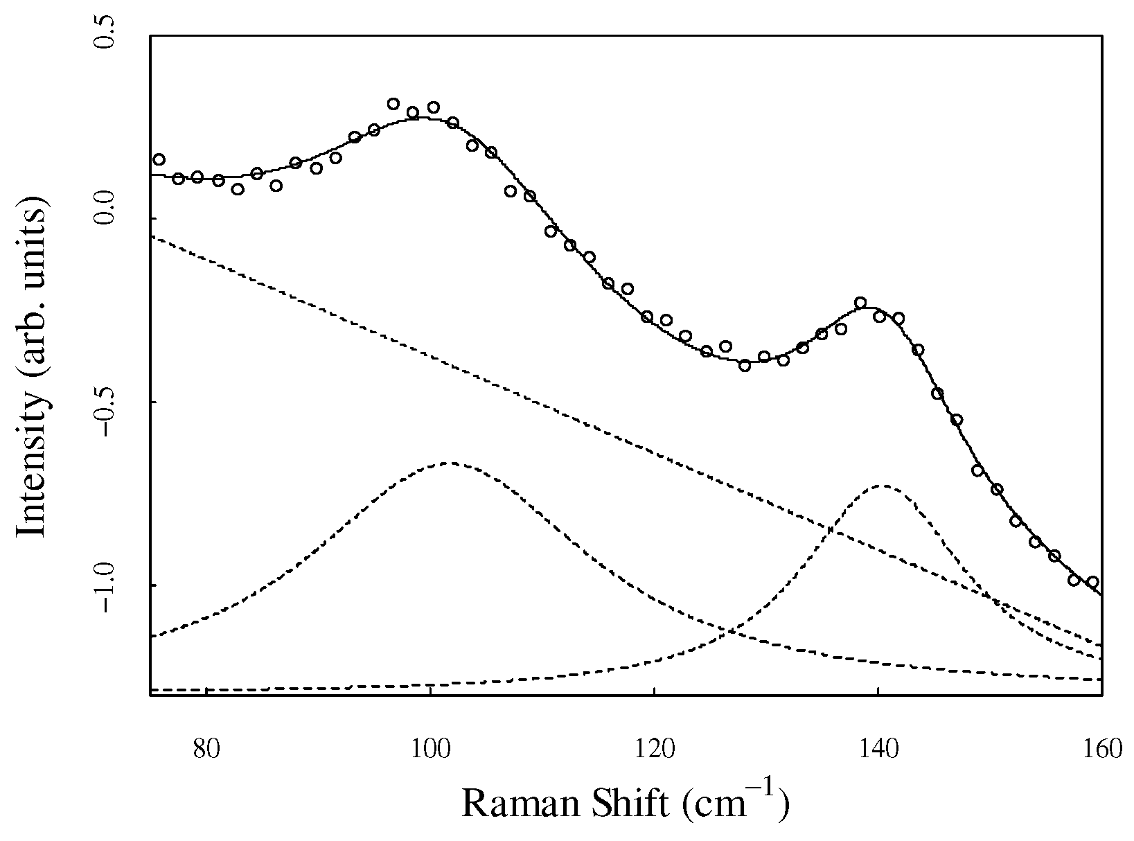
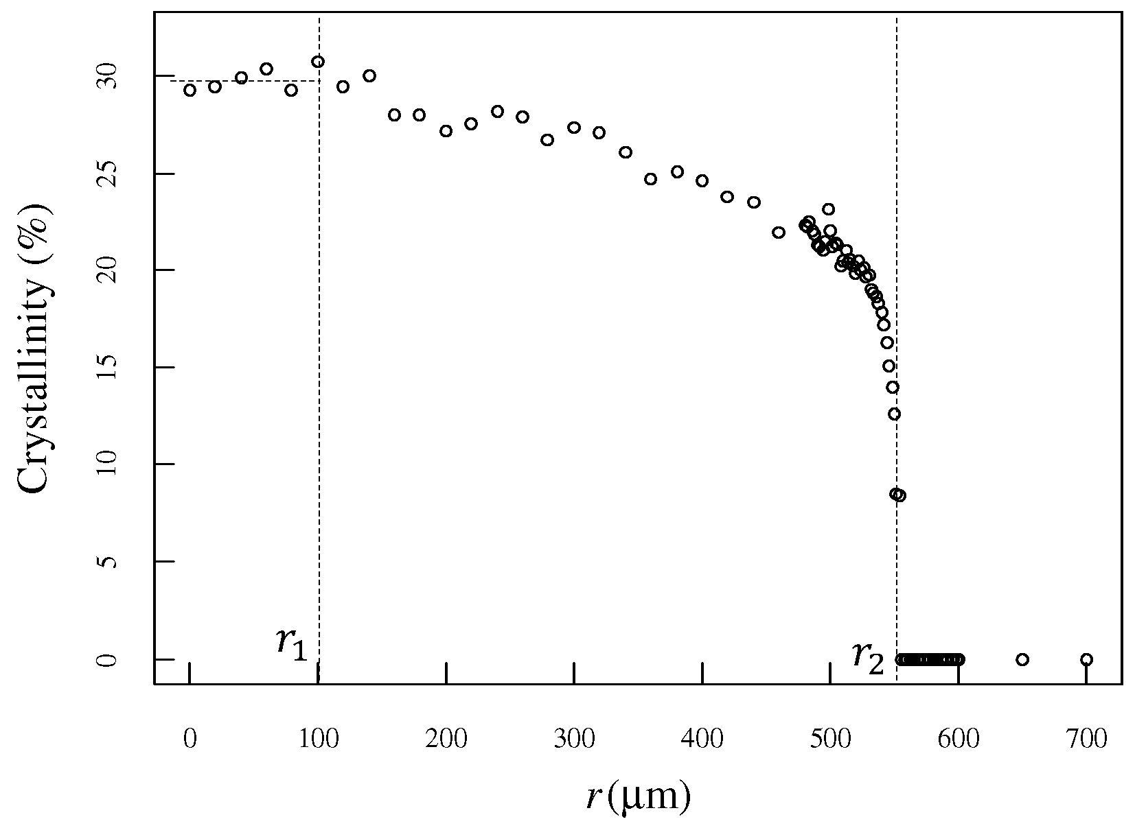
3. Results
4. Conclusions
Author Contributions
Funding
Institutional Review Board Statement
Informed Consent Statement
Data Availability Statement
Conflicts of Interest
References
- Blundell, D.J.; Osborn, B.N. The morphology of poly(aryl-ether-ether-ketone). Polymer 1983, 24, 953–958. [Google Scholar] [CrossRef]
- Biron, M. Handbook of Thermoplastic Elastomers; William Andrew Publishing: Norwich, NY, USA, 2012. [Google Scholar]
- Gao, S.-L.; Kim, J.-K. Cooling rate influences in carbon fibre/PEEK composites. Part 1. Crystallinity and interface adhesion. Compos. Part A Appl. Sci. Manuf. 2000, 31, 517–530. [Google Scholar] [CrossRef]
- Huo, P.; Cebe, P. Temperature-dependent relaxation of the crystal-amorphous interphase in poly(ether ether ketone). Macromolecules 1992, 25, 902–909. [Google Scholar] [CrossRef]
- Cogswell, F.N.; Hopprich, M. Environmental resistance of carbon fiber-reinforced polyether etherketone. Composites 1983, 14, 251–253. [Google Scholar] [CrossRef]
- Comer, A.J.; Ray, D.; Obande, W.O.; Jones, D.; Lyons, J.; Rosca, I.; O’Higgins, R.M.; McCarthy, M.A. Mechanical characterization of carbon fibre–PEEK manufactured by laser-assisted automated-tape-placement and autoclave. Compos. Part A Appl. Sci. Manuf. 2015, 69, 10–20. [Google Scholar] [CrossRef]
- Deignan, A.; Stanley, W.; McCarthy, M. Insights into wide variations in carbon fiber/polyetheretherketone rheology data under automated tape placement processing conditions. J. Compos. Mater. 2018, 52, 2213–2228. [Google Scholar] [CrossRef]
- Yang, D.; Cao, Y.; Zhang, Z.; Yin, Y.; Li, D. Effects of crystallinity control on mechanical properties of 3D-printed short-carbon-fiber-reinforced polyether ether ketone composites. Polym. Test. 2021, 97, 107149. [Google Scholar] [CrossRef]
- Jiang, W.; Chen, C.; Chen, Z.; Huang, Z.; Zhou, H. Effect of crystallinity on optical properties of PEEK prepreg tapes for laser-assisted automated fiber placement. Compos. Commun. 2023, 38, 101490. [Google Scholar] [CrossRef]
- Rusakov, D.; Menner, A.; Spieckermann, F.; Wilhelm, H.; Bismarck, A. Morphology and properties of foamed high crystallinity PEEK prepared by high temperature thermally induced phase separation. J. Appl. Polym. Sci. 2021, 139, 5143. [Google Scholar] [CrossRef]
- Zhen, H.; Zhao, B.; Quan, L.; Fu, J. Effect of 3D Printing Process Parameters and Heat Treatment Conditions on the Mechanical Properties and Microstructure of PEEK Parts. Polymers 2023, 15, 2209. [Google Scholar] [CrossRef]
- Katsifis, G.A.; Suchowerska, N.; McKenzie, D.R. Optical properties of plasma-treated PEEK: Monitoring colour and crystallinity for applications in medicine and dentistry using ellipsometry. Plasma Process. Polym. 2022, 19, 2100241. [Google Scholar] [CrossRef]
- Regis, M.; Bellare, A.; Pascolini, T.; Bracco, P. Characterization of thermally annealed PEEK and CFR-PEEK composites: Structure-properties relationships. Polym. Degrad. Stab. 2017, 136, 121–130. [Google Scholar] [CrossRef]
- Doumeng, M.; Makhlouf, L.; Berthet, F.; Marsan, O.; Delbé, K.; Denape, J.; Chabert, F. A comparative study of the crystallinity of polyetheretherketone by using density, DSC, XRD, and Raman spectroscopy techniques. Polym. Test. 2021, 93, 106878. [Google Scholar] [CrossRef]
- Doumeng, M.; Ferry, F.; Delbé, K.; Mérian, T.; Chabert, F.; Berthet, F.; Marsan, O.; Nassiet, V.; Denape, J. Evolution of crystallinity of PEEK and glass-fibre reinforced PEEK under tribological conditions using Raman spectroscopy. Wear 2019, 426–427, 1040–1046. [Google Scholar] [CrossRef]
- Bas, C.; Battesti, P.; Albérola, N.D. Crystallization and melting behaviors of poly(aryletheretherketone) (PEEK) on origin of double melting peaks. J. Appl. Polym. Sci. 1994, 53, 1745–1757. [Google Scholar] [CrossRef]
- Louden, J.D. Crystallinity in poly(aryl ether ketone) films studied by raman spectroscopy. Polym. Commun. 1986, 27, 82–84. [Google Scholar]
- Everall, N.J.; Chalmers, J.M.; Ferwerda, R.; van der Maas, J.H.; Hendra, P.J. Measurement of poly(aryl ether ether ketone) crystallinity in isotropic and uniaxial samples using Fourier transform-Raman spectrocopy: A comparison of univariate and partial least-squares calibrations. J. Raman Spectrosc. 1994, 25, 43–51. [Google Scholar] [CrossRef]
- Briscoe, B.J.; Stuart, B.H.; Thomas, P.S.; Williams, D.R. A comparison of thermal- and solvent-induced relaxation of poly(ether ether ketone) using Fourier transform Raman spectroscopy. Spectrochim. Acta A Mol. Biomol. Spectrosc. 1991, 47, 1299–1303. [Google Scholar] [CrossRef]
- Ellis, G.; Naffakh, M.; Marco, C.; Hendra, P.J. Fourier transform Raman spectroscopy in the study of technological polymers Part 1: Poly(aryl ether ketones), their composites and blends. Spectrochim. Acta A Mol. Biomol. Spectrosc. 1997, 53, 2279–2294. [Google Scholar] [CrossRef]
- Hsu, S.L.; Patel, J.; Zhao, W. Molecular Characterization of Polymers: A Fundamental Guide; Chapter 10; Elsevier Science: Amsterdam, The Netherlands, 2021; p. 369. [Google Scholar]
- Lee, Y.; Porter, R.S. Crystallization of poly(etheretherketone) (PEEK) in carbon fiber composites. Polym. Eng. Sci. 1986, 26, 633–639. [Google Scholar] [CrossRef]
- Uematsu, H.; Kawasaki, T.; Koizumi, K.; Yamaguchi, A.; Sugihara, S.; Yamane, M.; Kawabe, K.; Ozaki, Y.; Tanoue, S. Relationship between crystalline structure of polyamide 6 within carbon fibers and their mechanical properties studied using Micro-Raman spectroscopy. Polymer 2021, 223, 123711. [Google Scholar] [CrossRef]
- Yang, Y.; Chen, M.; Li, H.; Li, H. The degree of crystallinity exhibiting a spatial distribution in polymer films. Eur. Polym. J. 2018, 107, 303–307. [Google Scholar] [CrossRef]
- Segawa, T.; Ito, K.; Hatayama, M.; Maruyama, Y.; Gao, J.; Ueno, N.; Sato, H. Visualization of Changes in Crystallinity and Intermolecular Hydrogen Bonding of Poly(ε-caprolactone) during Marine Degradation Process by High- and Low-Frequency Three-Dimensional Raman Mapping. Appl. Polym. Mater. 2024, 6, 6408–6415. [Google Scholar] [CrossRef]
- Funaki, C.; Yamamoto, S.; Hoshina, H.; Ozaki, Y.; Sato, H. Three different kinds of weak C-H⋯O=C inter- and intramolecular interactions in poly(ε-caprolactone) studied by using terahertz spectroscopy, infrared spectroscopy and quantum chemical calculations. Polymer 2018, 137, 245–254. [Google Scholar] [CrossRef]
- Funaki, C.; Toyouchi, T.; Hoshina, H.; Ozaki, Y.; Sato, H. Terahertz imaging of the distribution of crystallinity and crystalline orientation in a poly(ε-caprolactone) film. Appl. Spectrosc. 2017, 71, 1537–1542. [Google Scholar] [CrossRef]
- Kaneko, T.; Hirai, N.; Ohki, Y. Terahertz absorption spectroscopy of poly(ether ether ketone). In Proceedings of the 2017 International Symposium on Electrical Insulating Materials, Toyohashi, Japan, 11–15 September 2017; pp. 539–542. [Google Scholar] [CrossRef]
- Hiroshiba, N.; Akiraka, M.; Kojima, H.; Ohnishi, S.; Ebata, A.; Tsuji, H.; Tanaka, S.; Koike, K.; Ariyoshi, S. Broadband infrared absorption spectroscopy of low-frequency inter-molecular vibrations in crystalline poly(L-lactide). Phys. B Condens. Matter 2023, 649, 414488. [Google Scholar] [CrossRef]
- Walker, G.; Römann, P.; Poller, B.; Löbmann, K.; Grohganz, H.; Rooney, J.S.; Huff, G.S.; Smith, G.P.S.; Rades, T.; Gordon, K.C.; et al. Probing pharmaceutical mixtures during milling: The potency of low-frequency raman spectroscopy in identifying disorder. Mol. Pharm. 2017, 14, 4675–4684. [Google Scholar] [CrossRef]
- Lipiäinen, T.; Fraser-Miller, S.J.; Gordon, K.C.; Strachan, C.J. Direct comparison of low- and mid-frequency Raman spectroscopy for quantitative solid-state pharmaceutical analysis. J. Pharm. Biomed. Anal. 2018, 149, 343–350. [Google Scholar] [CrossRef]
- Yamamoto, S.; Ohnishi, E.; Sato, H.; Hoshina, H.; Ishikawa, D.; Ozaki, Y. Low-frequency vibrational modes of Nylon 6 studied by using infrared and raman spectroscopies and density functional theory calculations. J. Phys. Chem. B 2019, 123, 5368–5376. [Google Scholar] [CrossRef]
- Yamamoto, S.; Miyada, M.; Sato, H.; Hoshina, H.; Ozaki, Y. Low-Frequency Vibrational Modes of poly(glycolic acid) and Thermal Expansion of Crystal Lattice Assigned on the Basis of DFT-Spectral Simulation Aided with a Fragment Method. J. Phys. Chem. B 2017, 121, 1128–1138. [Google Scholar] [CrossRef]
- Yamaguchi, M.; Kobayasi, S.; Numata, T.; Kamihara, N.; Shimda, T.; Jikei, M.; Muraoka, M.; Barnsley, J.E.; Fraser-Miller, S.J.; Gordon, K.C. Evaluation of crystallinity in carbon fiber-reinforced poly(ether ether ketone) by using infrared low frequency Raman spectroscopy. J. Appl. Polym. Sci. 2022, 139, 51677. [Google Scholar] [CrossRef]
- Numata, T.; Ishikawa, N.; Shimada, T.; Gordon, K.C.; Yamaguchi, M. Low-Frequency Raman Spectroscopy on Amorphous Poly(Ether Ether Ketone) (PEEK). Materials 2024, 17, 3755. [Google Scholar] [CrossRef] [PubMed]
- Yang, X.; Yokokura, S.; Nagahama, T.; Yamaguchi, M.; Shimada, T. Molecular Dynamics simulation of poly(ether ether ketone) (PEEK) polymer to analyze intermolecular ordering by low wavenumber raman spectroscopy and X-ray diffraction. Polymers 2022, 14, 5406. [Google Scholar] [CrossRef] [PubMed]
- Walter, J.; Brodesser, A.; Hustedt, M.; Bluemel, S.; Jaeschke, P.; Kaierle, S. Laser Processing of Carbon Fiber Reinforced Plastics—Release of Carbon Fiber Segments During Short-pulsed Laser Processing of CFRP. Phys. Procedia 2016, 83, 1021–1030. [Google Scholar] [CrossRef]
- Li, Q.; Perrie, W.; Tang, Y.; Allegre, O.; Ho, J.; Chalker, P.; Li, Z.; Edwardson, S.; Dearden, G. A study on ultrafast laser micromachining and optical properties of amorphous polyether(ether)ketone (PEEK) films. Procedia CIRP 2020, 94, 840–845. [Google Scholar] [CrossRef]
- Guinet, Y.; Paccou, L.; Hédoux, A. Low-Frequency Raman Spectroscopy: An Exceptional Tool for Exploring Metastability Driven States Induced by Dehydration. Pharmaceutics 2023, 15, 1955. [Google Scholar] [CrossRef]


Disclaimer/Publisher’s Note: The statements, opinions and data contained in all publications are solely those of the individual author(s) and contributor(s) and not of MDPI and/or the editor(s). MDPI and/or the editor(s) disclaim responsibility for any injury to people or property resulting from any ideas, methods, instructions or products referred to in the content. |
© 2024 by the authors. Licensee MDPI, Basel, Switzerland. This article is an open access article distributed under the terms and conditions of the Creative Commons Attribution (CC BY) license (https://creativecommons.org/licenses/by/4.0/).
Share and Cite
Numata, T.; Ishikawa, N.; Shimada, T.; Gordon, K.C.; Yamaguchi, M. Evaluation of Spatial Distribution of Crystallinity Induced by Local Heating Using Low-Frequency Raman Spectroscopy on Polyether Ether Ketone (PEEK). Spectrosc. J. 2024, 2, 341-348. https://doi.org/10.3390/spectroscj2040021
Numata T, Ishikawa N, Shimada T, Gordon KC, Yamaguchi M. Evaluation of Spatial Distribution of Crystallinity Induced by Local Heating Using Low-Frequency Raman Spectroscopy on Polyether Ether Ketone (PEEK). Spectroscopy Journal. 2024; 2(4):341-348. https://doi.org/10.3390/spectroscj2040021
Chicago/Turabian StyleNumata, Tomoko, Naomoto Ishikawa, Toshihiro Shimada, Keith C. Gordon, and Makoto Yamaguchi. 2024. "Evaluation of Spatial Distribution of Crystallinity Induced by Local Heating Using Low-Frequency Raman Spectroscopy on Polyether Ether Ketone (PEEK)" Spectroscopy Journal 2, no. 4: 341-348. https://doi.org/10.3390/spectroscj2040021
APA StyleNumata, T., Ishikawa, N., Shimada, T., Gordon, K. C., & Yamaguchi, M. (2024). Evaluation of Spatial Distribution of Crystallinity Induced by Local Heating Using Low-Frequency Raman Spectroscopy on Polyether Ether Ketone (PEEK). Spectroscopy Journal, 2(4), 341-348. https://doi.org/10.3390/spectroscj2040021