1. Introduction
Currently, the generation of electricity in most of the countries of the world is performed using fossil fuels. This situation is unsustainable because these resources (oil, natural gas, coal) are finite and their extraction processes are highly polluting. Therefore, to ensure the supply of electricity, and to meet the future energy demand in a way which is less aggressive for the environment, it is necessary to develop new electricity forms and generation strategies.
A viable option for this growing energy demand could be covered with waste, since there are a wide range of technologies which treat waste as an energy resource. Xiong et al. [
1] state that the process of waste treatment and energy recovery is called the waste-to-energy (WtE) system boundary. WtE handles the remainder of non-recyclable municipal solid waste (MSW) and includes activities such as volume reduction, energy product recovery and residual treatments. The use of MSW as an energy source is a possible and practical idea, and Baran et al. [
2], Soltani et al. [
3], Hammed et al. [
4] and Mukherjee et al. [
5] state that WtE can help to solve both electricity shortage problems and waste management problems. WtE processes reduce the volume of MSW (approximately 50–90%), and each ton of MSW treated could obtain energy equivalent of 0.13 to 0.38 tons of oil (toe) [
6]. The United Kingdom has a targeted increase in the proportion of its energy use of 15%, considering that one-third of the required energy could be supplied with biomass [
7]. The energy recovery could be increased, considering that, according to Ray et al. [
8], only a limited fraction of the MSW produced is used to produce energy.
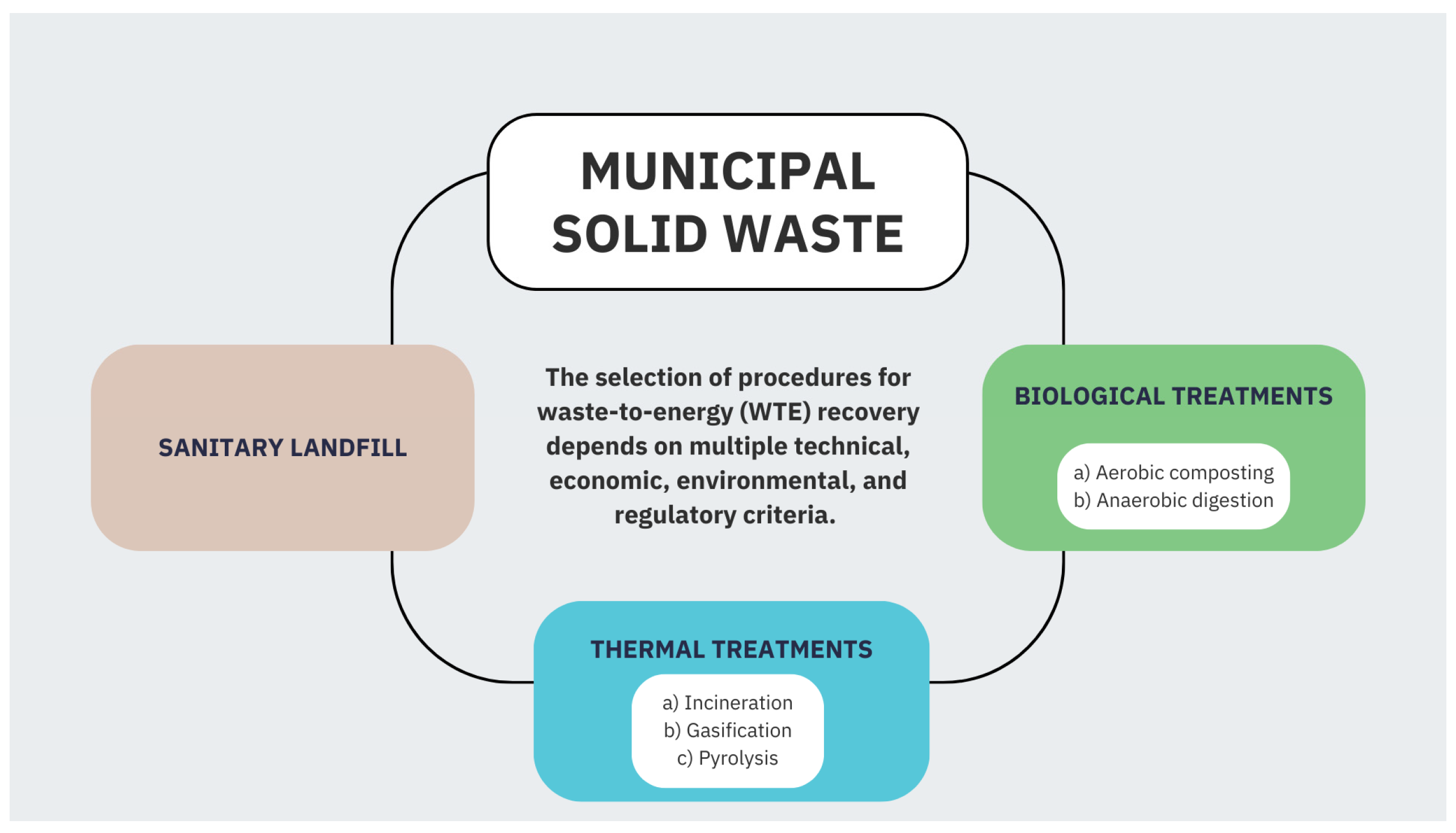
The current methods of waste treatment can be categorized into three types: thermal treatments, biological treatments and sanitary landfills (see
Figure 1). Tan et al. [
9] and Tozlu et al. [
10] state that WtE thermal treatment options use high temperatures to convert waste feedstock to produce electricity, heat and value-added products. The biological treatment of WtE converts organic waste into energy in the form of liquid or gaseous fuels through the use of biological agents. A sanitary landfill equipped with methane gas recovery (CH
4) and turbines can produce electricity and heat.
The energy potential in waste is high. According to Scarlat et al. [
11], the global potential for energy from waste was in the range of 8–18 EJ per year in 2010, with the possibility to increase from 13 to 30 EJ in 2025, assuming the calorific value of municipal waste is between 6 and 14 MJ/kg. Quaghebeur et al. [
12] found that fuel materials in excavated waste comprised 23% and 50% of the total weight, offering a significant energy potential of approximately 18 MJ per kg of dry waste. In the European Union, the recovery of energy through the incineration of urban solid waste produced energy equivalent to more than 8 million tons of oil in 2010, with a waste treatment capacity of 73 million tons. This capacity was expected to rise to 85 million tons by the end of 2016, and 94 million tons by 2020. Scarlat et al. [
11] reported that, in 2010, over 600 WtE facilities existed globally, with the majority located in Europe (472 in Norway, the EU and Switzerland), Japan (100) and the USA (86). Mukherjee et al. [
5] indicated that WtE systems are uncommon because of their high initial investment costs and the requirement for substantial local government backing. There are currently 765 MSW-based WtE plants worldwide, with an annual capacity of 83 million tons. In the US, 86 municipal solid WtE combustion facilities operate across 25 states. In 2014, China had 200 waste incineration plants, and the government announced plans to increase that number to 300 by the end of 2020. India currently has just eight operational WtE thermal plants, with a combined capacity of 94.1 MW, and an additional fifty WtE projects are nearing completion. Japan is the global leader in energy recovery from waste, achieving nearly 78% WtE conversion and sending the remaining 22% to composting and recycling. Europe has 455 WtE plants in 18 European countries.
The application of technological developments for solid waste management and the recovery of energy is not an easy task. The selection of WtE technologies in each of the waste treatments will depend on the composition and characteristics of the waste, capital and operating costs, technological efficiency and complexity, along with the qualification requirements and geographical locations of the plants [
6,
13]. Farooq et al. [
14] report that biological treatments like anaerobic digestion are ideal for organic waste, while thermal treatments such as gasification are suitable for combustible fractions of organic and inorganic MSW. Rezania et al. [
15] state that the regulations and policy framework must also be considered, as understanding policy incentives or barriers can influence technology selection and project design. Hence, it is essential to conduct a study that supports stakeholders in sanitation systems in making well-informed choices about management practices and technology selection. Technology will be adopted when (a) the waste stream has a sufficient calorific value and composition, (b) the selected technology meets environmental and emission standards, (c) the project is economically feasible with sustainable revenue generation, (d) there is regulatory support and public acceptance and (e) alternative waste treatment methods (landfilling, recycling) are less viable. Therefore, the purpose of this study is to analyze the anaerobic digesters, gasifiers and plasma gasifier technologies used for waste energy recovery and to describe their basic principles, peculiarities and applications.
2. Valorization of Solid Waste with Anaerobic Digestion
Anaerobic digestion (AD) is a technique for the fermentation of organic material in oxygen-free conditions. The result is a gaseous fuel called biogas, which contains mainly methane (CH
4) and carbon dioxide (CO
2), but often carries impurities such as moisture, hydrogen sulfide (H
2S), siloxanes and particulate matter [
9,
16,
17]. To improve biogas quality, it is necessary to eliminate CO
2 and contaminants. However, for its optimal use, it is necessary to know the specifications of the engine and the standards of the pipes that will be used for the generation of renewable energy and fuel for vehicles. The cost of the biogas improvement is in the range of USD 0.13–0.29 per m
3 of methane, depending on the design capacity of the system (100–2000 Nm
3 biogas per hour) and the improvement of the technology [
16].
The AD process involves four primary biological and chemical stages: hydrolysis, acidogenesis, acetogenesis and methanogenesis [
18]. During hydrolysis, complex organic compounds are broken down into simpler molecules, such as fatty acids, monosaccha-rides, amino acids and other related substances. In the following stage, acidogenesis, the remaining components are further broken down by acidogenic (fermentative) bacteria, producing gases like CH
4, CO
2 and NH
3. During acetogenesis, the simple molecules produced in the acidogenesis phase are further processed by acetogens to primarily form acetic acid, along with carbon dioxide and hydrogen gas. The final stage, methanogenesis, sees methanogenic bacteria converting these intermediate products into CH
4, CO
2 and H
2O [
9,
17,
19]. In optimal conditions, the AD of a ton of organic MSW can produce a net energy of approximately 9–13.5 kg of oil equivalent (kgoe). Different anaerobic digestion methods, such as mesophilic and thermophilic, generate more energy than they use, but the batch pre-treatment provides the highest net energy output [
6,
20].
The bacteria involved in the biogas production process are sensitive to certain factors. Hence, in the operation of a digester, the following should be considered: temperature and type of substrate (organic matter to be used), total solids (TS) in the substrate, inside temperature, pH (measure of acidity or alkalinity), carbon/nitrogen (C/N) ratio, retention time, degree of mixing, the addition of inoculants and the presence of compounds that inhibit the process [
17,
21,
22,
23]. Garfí et al. [
19] state that the optimal C/N ratio in the substrate is 15–45. A neutral pH is favorable for biogas production, in the range of 6.7–7.5. The concentration of TS in the digester can vary from 2 to 15% (low-solid anaerobic digestion) to 15–40% (high-solid anaerobic digestion). Temperature ranges are categorized based on the ideal growth conditions for various methanogenic microorganisms: psychrophilic (<25 °C), mesophilic (30–40 °C) and thermophilic (50–60 °C). Typically, higher temperatures lead to faster reaction rates and, as a result, biogas production increases and smaller volumes are needed. Xu et al. [
24] point out that a substantial number of food additives (e.g., salt, allyl isothiocyanate, nonnutritive sweeteners, allicin, capsaicin and monosodium glutamate) are present in food waste. Their interactions with anaerobic digestion, in which they negatively affect anaerobic digestion by deactivating functional enzymes, are typically overlooked.
Sharma et al. [
25] note that the rate of the anaerobic digestion (AD) process is influenced by microbial communities that play a key role in oxidation–reduction reactions. The interactions of electrons between different microbial groups, particularly syntrophs and methanogens, governs the AD rate and kinetics. Understanding this electron transfer mechanism, known as direct interspecies electron transfer (DIET), is crucial for improving the design and prediction of AD processes. DIET has been shown to enhance the exchange of hydrogen and electrons between syntrophic and methanogenic microbes.
The advantages of AD include the reduced cost of the process and the higher process efficiency (25–30%), compared to other WtE technologies [
13,
20]. Biodegradable organic waste, such as food waste, sewage sludge, animal manure, among others, can be treated with the AD process [
26]. The AD of organic materials is a widely used method for energy recovery and waste management in Europe, utilizing source-separated organic (SSO) waste and agricultural residues as feedstock. In contrast, the commercial use of AD in the US is limited. In the greater Newmarket and Toronto areas, there are two commercial plants dedicated to processing SSO waste, and several smaller facilities in the US operate using a combination of MSW, SSO waste, or co-digestion with biosolids.
Small-scale AD has been implemented in the rural regions of countries like China and India. By 1993, approximately 5.25 million farm households had adopted digesters, producing nearly 1200 million cubic meters of CH
4 and generating a total power output of 3500 kW. In Nepal, the use of small-scale digesters (4–10 m
3) has significantly grown in recent years. The biogas produced is used for cooking and, in 25% of households, it is also used for generating electricity [
27]. In Mexico, there is experience with the use of digesters to take advantage of waste and generate energy. These applications are mainly presented in the livestock sector to reduce environmental problems and reduce electricity costs. The SAGARPA [
28] indicated that in 2010, 139 digesters were installed, of which 59 were motor generators. Globalmethane [
29] reported that the Mexican States in which the largest number of digesters were installed were Yucatan (41), Coahuila (39), Jalisco (21), Aguascalientes (7) and Nuevo Leon (7). The AD process has the lowest annual net capital cost (USD 0.1–0.14/ton) and has an operating cost per minimum ton. It is possible to obtain 120 to 150 m
3 of biogas per ton of dry MSW, which is equivalent to 2500 MJ/ton [
13].
In recent years, applications using microbial fuel cells (MFCs) with AD have been implemented. The objective is to increase the use of energy contained in biomass through the simultaneous production of electricity and biogas. The methane produced in AD is used as fuel in engine–generator sets (gen-sets) to generate electricity (high voltage of 220 v), while bacteria transfer the electrons present in organic substrates to MFCs to produce bio-electricity (low voltage of 0.5–0.7 V in a single MFC). Sharma et al. [
30] indicated that this concept has been used in sugar food waste, industry effluent, ethanol from kitchen waste, methane from polylactic acid and electricity from chicken feathers. However, large-scale trials are also needed for the commercialization of the process.
An additional benefit of AD is its by-product being a good soil conditioner. The organic waste that entered the digester (equipment where AD is performed, also known as anaerobic digesters or reactors) can be digested and returned to the environment in the form of fertilizer and fuel, without degrading the environment. This process preserves, and even improves, the nutritional value of the original raw material. It has been shown that the use of a liquid mixture composed of biogas plants in agriculture can increase the yield of rice, corn, wheat and cotton by 5.6%, 8.9%, 15.2% and 15.7%, respectively [
31].
Classification of Digesters
Digesters are made in various designs and configurations, categorized based on fac-tors such as the dry solid content of the input material, the number of processing stages, the operating temperature and how the substrate is fed into the system (refer to
Table 1). Examples of these include dry batch or dry continuous processes for high-solid substrates, which are commonly used for the organic components of MSW, and the up-flow anaerobic sludge blanket system [
17,
32].
Table 2 outlines the pros and cons of each digester type, considering factors such as substrate type, operating conditions, pre-treatment requirements and potential outcomes.
The stage-separated AD process has demonstrated advantages such as increased methane production (from 5.8% to 65.5%), energy recovery (from 9.8% to 65.5%) and a shorter payback period (9 years) than that of single-stage systems (11.7 to 23.4 years). These advantages are due to a more efficient methanogenesis process and stability in the methanogenic phase, even with a wide range of organic loading rates, maturity and widespread application [
18].
3. Valorization of Solid Waste with Gasification
Gasification is an energy technique employed to reduce the volume of solid waste and recover energy. This refers to the thermochemical conversion of a solid material through partial oxidation. Using air or oxygen and indirect heating, synthesis gases (syngas) are produced that mainly contain CO, H
2, CH
4, light hydrocarbons, CO
2 and N
2, depending on the process used [
9,
13,
16,
33,
34,
35]. In the gasification process, the waste is burned with controlled oxygen to generate enough heat for the primary syngas reaction, using temperatures between 600 °C and 1700 °C [
6,
8,
9,
16,
36].
The syngas produced through gasification can be used in gas turbines or for combustion in standard boilers. Engvall et al. [
37] indicate that gasification using air produces a gas rich in N
2 (50–65%) and low in calorific value (4–8 MJ/Nm
3). When oxygen is used as the gasifying agent, the resulting syngas has a low nitrogen content and a high calorific value (ranging from 10 to 18 MJ/Nm
3), making it suitable for various applications such as feeding fuel cells, hydrogen production and synthesizing fuels and chemicals. In fluidized bed gasification with oxygen/steam as the gasifying agent, the typical gas product composition has a calorific value of 13.8 MJ/Nm
3 (dry). Ray et al. [
8] point out that the composition of syngas is dependent on the gasification process, fuel used and gasifying agents (air, oxygen, steam and carbon dioxide). The generated syngas usually contains between 30 and 60% CO, 25 and 30% H
2, 0 and 5% CH
4, 5 and 15% CO
2 and trace amounts of water vapor, sulfur compounds, H
2S, NH
3 and other pollutants. Some researchers [
38,
39] state that when a gasifier is operating at atmospheric pressure with air as an oxidant, the final products of the gasification process are coke (carbon + inert materials originally in the fuel), condensable liquids similar to pyrolytic oil and gas with a low calorific value that normally contains 10% CO
2, 20% CO, 15% H
2, 2% CH
4 and with the remainder comprising N
2. Due to the diluting effect of nitrogen in the inlet air, the low calorific gas has an energy content of approximately 5600 kJ/m
3. Alao et al. [
40] state that when air is used as the gasifying agent, the syngas’ lower heating value (LHV) is between 4 and 7 MJ/Nm
3. When pure oxygen is used as the gasifying agent, the syngas is nitrogen-free and reaches an LHV from 10 to 15 MJ/Nm
3. In steam gasification, the generated syngas reaches an LHV from 5 to 20 MJ/Nm
3 because it has a high hydrogen concentration and is free of nitrogen.
The waste gasification can reduce the volume of waste to between 50% and 90% [
41] and can recover 1.9 to 3.8 MW per ton of waste, compared to disposal in landfills [
13]. The ISR [
42] mentions that the efficiencies of transforming waste into energy are lower in a gasification plant than in total combustion plants. These losses can represent 25–30% of the calorific power (CP) of the waste, so that the net energy of the lean gas before compression for entry into the engine or turbine will be 70–75% of the primary energy of the waste. If the overall performance of the engine generator is of the order of 35% with respect to the CP of the lean gas, the total generation will be around 26–27% of the CP of the waste. This value is deducted from the self-consumption of the installation, which will reduce the net export of the energy to values which are 22% of the CP of the waste fed. Ouda et al. [
13] estimate that a net power generation potential of 20 to 26 kW/ton of MSW can be obtained. In addition, Munir et al. [
6] and Hoang et al. [
20] indicate that gasification can produce net energy among 36 to 63 kgoe/ton of MSW treated.
The gasification of the combustible materials used can be carried out in various types of gasifiers (see
Figure 2). They are classified depending on the type of gasifying agent, the type of gas–solid contact, the direction and gas–solid relative velocity, the working pressure and the method of supplying heat to the reactor. The type of gasifier determines the reaction kinetics, the yields, the composition of the products and the formation of contaminating species [
43].
3.1. Railed Bed Gasifier
The feed fuel in entrained flow gasifiers consists of very fine particles (0.1–1 mm), and the gasifying agent is injected in the co-current. The gasifier operates at high temperatures (1200–1500 °C) and pressures (25–30 bar), using raw material, water sludge or dry food. Pneumatic feed is typically used to inject powdered solid fuels, while suspensions are atomized and fed as pulverized fuel [
33,
44,
45]. Entrained flow gasifiers are classified into slag-producing and non-slag-producing types, with the latter having a maximum allowable ash content of 1%. Pre-treatment, such as roasting, is needed to reduce bulk density and moisture when using fine biomass particles as raw materials [
33].
Table 3 shows the advantages and disadvantages of this type of gasifier.
3.2. Fixed Bed Gasifier
This type of gasifier uses a grid to support the feed material and create a stationary reaction zone. It is simple to design and operate, making it suitable for small- to medium-scale energy and thermal applications. However, maintaining consistent temperatures and a proper gas mixture is challenging, leading to unpredictable gas yields, which makes it unsuitable for large-scale energy production (over 1 MW) [
46].
There are two primary types of fixed bed gasifiers (see
Table 4). They are characterized by a fuel bed that moves slowly downward under the action of gravity while gassing, feeding the gas in a downward (downdraft) or ascending (updraft) direction. Both types have the disadvantage of demanding requirements for fuel (particle size distribution, humidity, among others). There is another type of fixed bed gasifier, the crossdraft [
43].
Table 5 shows the advantages and disadvantages of each type of fixed bed gasifier.
3.3. Fluidized Bed Gasifier
Fluidized beds are ideal for MSW gasification, where air or steam is passed upward through a bed of solid fuel and inert material (e.g., sand or limestone). The gas is the fluidization medium and the oxidant for combustion and tar cracking. The fluidized bed behaves like a boiling liquid with fluid-like characteristics. Waste is introduced into the bed either through a feed pipe at the top or via an endless screw [
46].
Due to the better heat transfer, the fluid beds allow the processing of a greater amount of combustible material and a greater production of reaction gases. By maintaining a uniform temperature throughout the bed, the gasification reaction is also uniform, which favors the quality of the gases generated [
43]. Fluidized bed technology is ideal for generators over 10 MW in capacity, as it can handle multiple fuels, requires compact combustion chambers and offers reasonable operational control [
46].
Gasifiers use one of the two existing fluidized bed configurations: bubbling and circulating (see
Table 6). They share some common characteristics such as the average content of tars in the exhaust gas, the drag of solids and the moderate conversion of the fuel, similar to fixed bed gasifiers [
43,
49].
The fluidized bed gasifier is often adopted to expand the capacity of MSW elimination. The volume of feed to the gasifier must be large enough to match the capacity of the fluidized bed [
48]. Therefore, it is more complicated in terms of construction and operation, and also requires more investment.
Table 7 shows the advantages and disadvantages of this type of gasifier.
Another technology currently used is the rotary kiln gasifier [
4]. It consists of a sloped, rotating cylinder that facilitates air–solid interaction, improving contact between the solid material and the oxidizing agent. It offers high flexibility, easy construction, low investment cost and adaptability to feed variations; however, it is difficult to control, requires high maintenance and produces a large amount of tar.
The selection of gasifier technology is influenced by factors such as fuel characteristics, including particle size, morphology, moisture and ash content, ash melting point, apparent density and temperature profile. Other considerations include heat exchange, residence time, conversion efficiency and process flexibility [
40,
47,
49].
4. Plasma Gasification
It is a new technology requiring high capital and operational costs. Due to existing knowledge gaps, most systems are still at the lab or pilot stage and are being tested for industrial use. Qi et al. [
52] indicate that there is still a considerable distance to cover in transitioning from laboratory-scale research to practical industrial implementation due to differences between the gasification of complex MSW and the lab gasification of relatively simple and idealized materials. Currently, no commercial MSW plasma gasification technology is operational [
5,
53,
54]. Nemmour et al. [
55] point out that the commercialization of plasma gasification technology is limited and currently is used at just five locations worldwide, including China, Japan, India and Canada; no plasma gasification facilities for waste disposal have been built in Europe or North America as of yet.
Plasma gasification is a very recent development and bases its principle of operation on generating a high-temperature plasma (4000–7000 °C) to induce a pyrolysis process in the MSW [
46]. Rajasekhar et al. [
44] and Mazzoni et al. [
56] report that it can operate at temperatures of 1500–5000 °C. As in the pyrolysis and gasification processes, syngas is generated, and a vitrified slag rock with stable characteristics, with an added facility to obtain by-products such as metals [
33,
43,
57].
The plasma is generated in the reactor from plasma torches, which consist of electrodes in which an electric arc is induced, and through which a stream of inert gas is passed, which raises its temperature and becomes ionized, becoming a plasma. Upon the contact of the latter with the MSW, the matter is broken down into its atomic constituents, which then react with each other to form syngas [
44,
57,
58]. An electric arc between two electrodes, typically made of graphite or tungsten, regulates plasma temperature in the reactor. Laboratory or small-scale plasma torches use low voltages (100–300 V) and currents below one thousand amperes, while industrial torches for large-scale waste gasification operate at high voltages (1000–2000 V) and currents ranging from 1000 to 10,000 A [
59]. Leal [
60] reports that the plasma torch operates at very high temperatures, between 5000 and 10,000 °C, and can process all kinds of waste, including municipal, toxic, medical, biohazardous, industrial solids and nuclear waste, at atmospheric pressure. It does not produce ash, because at more than 5000 °C, all organic molecules disintegrate and only a mixture of H
2 + CO remains. With this process, a reduction in weight and volume of more than 90% is obtained. The synthesis gas generated contains dust (particles) and other undesirable elements, so it must undergo a cleaning process in order to be used for energy. For the case of the MSW, the gas cleaning consists of the elimination of particles, the separation of sulfur and mercury and the elimination of heavy metals [
43]. According to Qi et al. [
52], plasma gasification can reduce the waste volume by up to 95%.
Molino et al. [
33] describe two methods for using plasma technologies in the thermal treatment of organic materials: (1) Direct application to the solid, aiming for thermal destruction, which allows for temperature control regardless of fluctuations in the solid’s quality or the gasification agent, and can accommodate variations in flow rate, moisture, size and composition. (2) Application to the gas from an upstream gasification process, focusing on maximizing syngas production with high-light components while removing tar without changing the energy content of the syngas. Based on arc discharge techniques, plasma gasification can be classified into three categories: direct current (DC), microwave (MW) and radio frequency (RF) plasma [
55].
In the production of energy from various types of thermal process technologies, plasma arc gasification produces about 816 kWh/ton of MSW, compared to 685 kWh/ton with conventional gasification technology. Therefore, plasma arc gasification could be considered to be the most efficient thermal gasification process [
5,
61]. It is worth mentioning that this technology has not had the expected results, and several projects in the United States have had serious setbacks. However, this technology presents a vast future potential, and countries like Great Britain are in the process of developing plants for the production of bioethanol and electric power. One of its main disadvantages lies in the high energy consumed by plasma torches, which is taken from the same process, thus reducing the net electricity that can go to the electricity grid [
57]. About 40% would be used to operate the plasma and plant torches, and the remaining 60% could be sold to the electricity grid [
62]. Janajreh et al. [
63] report that plasma gasification has an average process efficiency of 42%, compared to 72% for conventional gasification. While plasma gasification is suitable for hazardous waste disposal and energy recovery, its low efficiency and high capital costs are significant limitations [
51]. The cost of construction for plasma gasification is approximately USD 65–200 million for a 500 tons/day plant, and operational and maintenance costs are also high, as noted by Munir et al. [
53]. Although plasma gasification can generate more revenue than pyrolysis and gasification, it is a relatively expensive technology with a shorter service life that requires more automation and proper waste sorting for the feed material. For these reasons, it has mainly been used for treating hazardous waste, and its use for waste-to-value processing is relatively new.
Nanda and Berruti [
64] have reported developing a plasma gasification melting process for converting MSW using an updraft moving-bed gasifier. Plasma torches heated the air to 6000 °C, melting and trapping the inorganic compounds of MSW as vitrified slag. The plasma power ranged from 2.88 to 3.12 MJ/kg of MSW, producing syngas with lower heating values (6–7 MJ/Nm
3). The maximum energy efficiency was 60%, though the tar formation caused energy loss. The slag contained inorganic materials and heavy metals from the MSW. It had a high density (2300 kg/m
3) and a slag-to-MSW volume ratio of 1:50. The slag exhibited the potential for use as a construction material.
5. Conclusions
Most countries currently generate electricity using fossil fuels, which is unsustainable due to the finite nature of these resources and their polluting extraction processes. A viable option is waste-to-energy, since there are a wide range of technologies to treat waste as an energy resource. When selecting procedures for WtE recovery, several key criteria should be considered to ensure the chosen technology aligns with environmental, economic and social objectives. Anaerobic digestion, gasification and plasma gasification represent key technologies for waste-to-energy recovery, each with unique benefits and applications.
Anaerobic digestion is ideal for biodegradable waste, providing both renewable energy and soil-enhancing digestate. AD is widely implemented across various regions, particularly in Europe, China and India, where it is used for electricity generation, cooking fuel and organic fertilizer production. However, its large-scale adoption in North America remains limited. Emerging applications, such as microbial fuel cells (MFCs), present opportunities for increasing energy recovery and efficiency. Despite challenges related to process optimization and impurity removal, AD remains one of the most cost-effective and environmentally friendly WtE solutions. It not only generates clean energy but also produces valuable by-products like nutrient-rich fertilizers, contributing to circular economy initiatives and sustainable agricultural practices.
Gasification is an effective thermochemical WtE technology that reduces solid waste volume while producing synthesis gas (syngas) as an energy carrier. The calorific value of syngas plays a crucial role in its application, making it suitable for power generation, hydrogen production and synthetic fuel synthesis. System efficiency is affected by factors such as gasifier type, process conditions and the self-consumption of generated energy, ultimately leading to a net energy export of approximately 22% of the calorific power of the waste. Overall, gasification is a promising WtE technology with flexible applications, offering improved waste management and sustainable energy production. Its effectiveness depends on optimizing gasifier design and process parameters to enhance syngas quality and energy recovery.
Plasma gasification is an advanced thermal WtE technology that utilizes extremely high temperatures to break down MSW into its atomic components, producing syngas and a vitrified slag by-product. While it offers significant reductions in waste volume and can process hazardous and complex waste streams, its commercial adoption remains limited due to high capital and operational costs, technical challenges and low process efficiency. Currently, plasma gasification remains at the lab or pilot stage, with only a few operational facilities worldwide. While it holds promise for hazardous waste treatment and high-efficiency syngas production, its widespread application for MSW processing is hindered by economic and technical barriers. Ongoing developments in automation, process optimization and energy efficiency improvements may enhance its viability in the future, particularly for specialized waste streams.


